

Page 1
FITTING INSTRUCTIONS
LH 1600
TRAM LINE MONITOR
LH No. 010-152-UK
SCA 0500
LH Technologies Denmark ApS
Mølhavevej 2
9440 Aabybro
Denmark
Tel. +45 9696 2500
Fax. +45 9696 2501
Internet: http://www.lh-agro.com/
Page 2
F
KEY DRAWING
ITTING INSTRUCTIONS
LH 1600
2 LH A
GRO
Page 3
F
ITTING INSTRUCTIONS
LH 1600
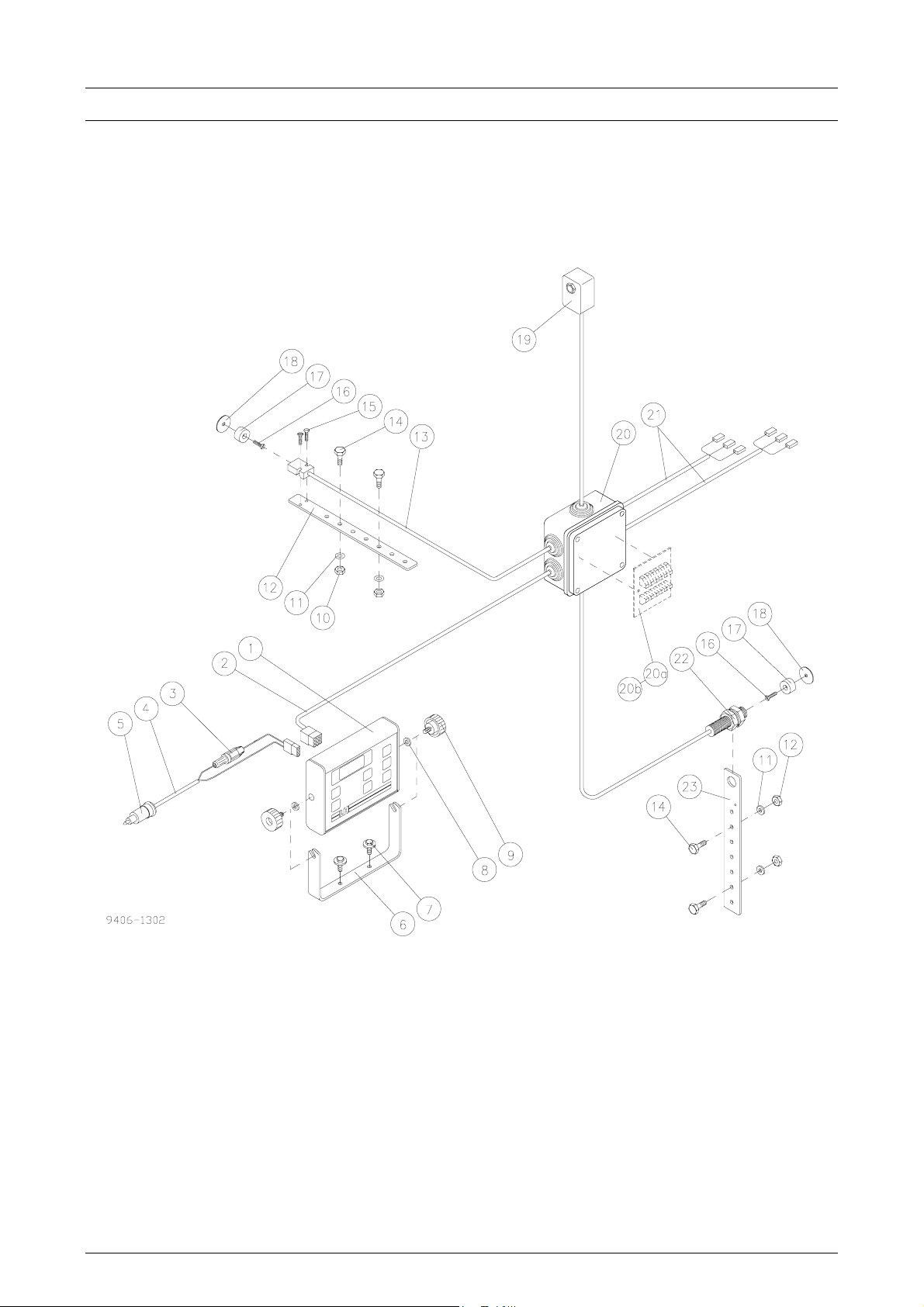
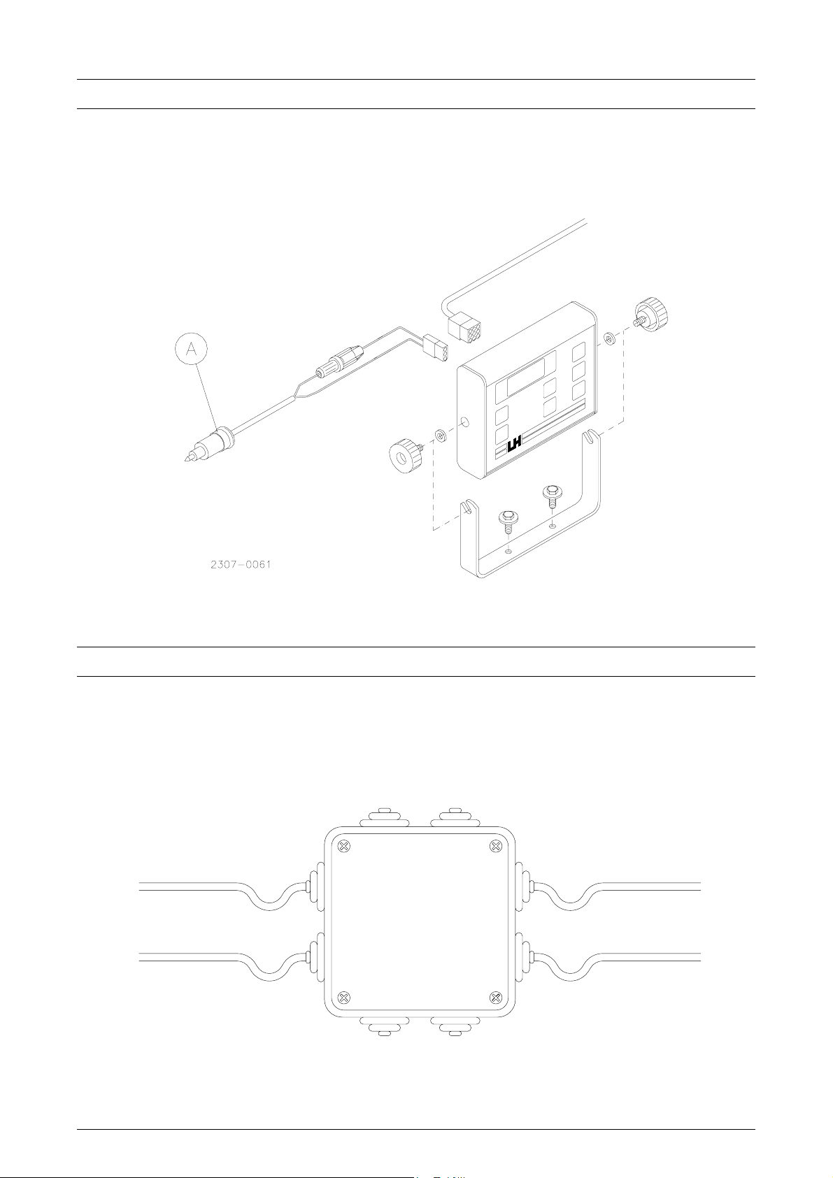
FITTING THE MONITOR IN THE TRACTOR
Mount the monitor in the cab within reach of the driver. Connect the monitor to the
12 V of the tractor via the 2-pole power plug A (fig. 1).
Fig. 1
FITTING THE JUNCTION BOX
Mount the junction box right in front on the drill. Mount it as protected as possible.
When the cables later are to connect in the box the cable must be long enough to
make a curve to ensure that water drips off and not runs into the junction box.
(Fig. 2)
Fig. 2
LH A
GRO 3
Page 4

F
ITTING INSTRUCTIONS
FITTING THE CLUTCHES AND THE CLUTCH CONTROLS
Dismount the metering shaft and insert the two clutches (with feeder wheel and
controls).
Clutches and controls are mounted so that the core output turns down and the flat
part of the housing makes contact with the hopper.
Lead the supplied cables along with the chassis tube to the junction box.
A metering shaft bearing shall be mounted as close to the clutch as possible. On
certain machine types it may be necessary to make an exchange of the force
feeds to get place for the clutches.
LH 1600
Fig. 3.
Fig. 4.
4 LH A
GRO
Page 5

F
ITTING INSTRUCTIONS
LH 1600
FITTING THE IMPLEMENT SENSOR
Mount the implement sensor so that it will register each time the drill is lifted
(magnet and sensor must face each other for min. 2-3 seconds).
Dependent on machine type and equipment there are various possibilities, say
marker change, marker cylinder, lift cylinder etc.
•
The magnet can be glued on with suitable glue (Pos. 17).
•
Do not thighten the screws (pos. 15) too hard.
Relieve the sensor cable (pos. 12 - 13) with a cable strip.
•
LH A
GRO 5
Page 6

F
FITTING THE WHEEL SENSOR
Mount the wheel sensor on the "traction wheel".
Use both supplied magnets to achieve a suitable wheel circumference.
ITTING INSTRUCTIONS
LH 1600
•
The magnets can be glued on with suitabel glue.
•
Do not thighten the lock nut of the sensor too hard.
The distance between sensor and magnet must be app. 5 mm.
•
6 LH A
GRO
Page 7

F
ITTING INSTRUCTIONS
LH 1600
FITTING THE TANK SENSOR (EXTRA EQUIPMENT)
Mount the tank sensor app. 150 mm over the bottom of the hopper between the
uttermost seed chamber in one of the sides.
Drill a hole the size of which suits for the sensor. Screw it direct into the plate (do
not thighten too hard).
LH A
GRO 7
Page 8

F
ELECTRIC CONNECTION
ITTING INSTRUCTIONS
LH 1600
6
5
RELAY
1
White
2
Brown
Green
3
4
Yellow
5
Pink
6
Grey
Blue
7
Red
8
Blue
9
Brown10
Drill connection box
+12V
0 V
Clutch
RPM 1
Clutch
RPM 2
Tank
Implement
Wheel
Clutch
Implement
0 V
11
12
13
2
3
5
6
8
9
Black1
Brown
Blue
Black
Brown
Blue7
Yellow
Blue
Brown14
RPM 1
Clutch 1
0 V
+12 V4 Yellow
RPM 2
Clutch 2
0 V
+12 V
+12 V
Tank10
0 V
+12 V
Wheel
0 V
LH AGRO
1
2
3
4
R
Pos. Connection
1 Left clutch and control
2 Right clutch and control
3 Level sensor (empty hopper)
4 Wheel sensor
5 Implement sensor
6 Main cable
Connection to pos. 3 for:
LH nr.: 904-151 LH nr.: 904-152
Connector: Color: Connector: Color:
9 Brown 9 Black
10 White 10 Red
11 Blue 11 Blue
8 LH A
GRO
 Loading...