

Page 1

FITTINGS INSTRUCTIONS
FOR
LH 1200 S
LH No. 010-202-UK
LH Technologies Denmark ApS
Mølhavevej 2
9440 Aabybro
Denmark
Tel. +45 9696 2500
Fax. +45 9696 2501
Internet: http://www.lh-agro.com/
Page 2
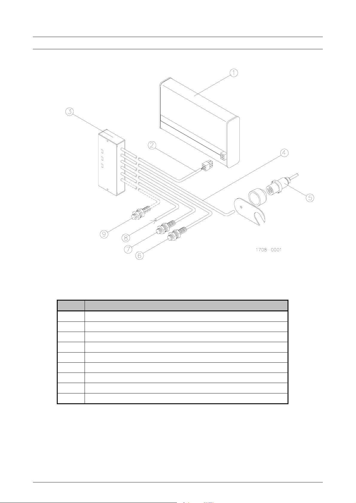
KEY DIAGRAM
Pos. Description
1
1200 S monitor
2
5 core connection cable
3
Junction box
4
Trailer socket cable
5
Trailer plug
6
Wheel sensor (2 core)
7
Override sensor (2 core)
8
Power 12V
9
(Optional) PTO/RPM sensor (3 core)
2 LH AGRO
Page 3
HOW TO MOUNT THE 1200 S
Monitor: Place the unit in the cabine. Check location of the junction box and
ensure right cable length.
Junction box: Place the unit in the cabine (Note: two versions! - with or without
switches. Only junction boxes with switches can be connected to a
PTO/RPM sensor).
Pull away plug: Mount on the near side of the tractor (see diagram).
Speed transmit: Mount on the right rear wheel (see diagram). If you wish to
measure, using a 4 WD drive shaft you must use a special sensor.
A description of these follow.
Override sensor: Mount on the tractors lift arms (see diagram).
Power: Always connect through the ignition switch
PTO/RPM: (Extra) Sensor to measure revolutions (PTO-motors etc.). The
sensor set including a magnet ring for axels need to be ordered
separatly.
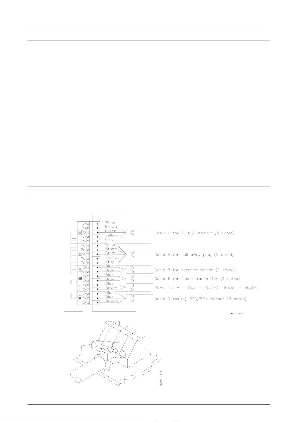
CONNECTIONS IN THE JUNCTION BOX
FOLLOW THE COLOUR CODES ON THE CIRCUIT BOARD AN CABLES
Attach all cables to the
circuit board using the
supplied straps.
LH AGRO 3
Page 4

CONNECTIONS IN THE PULL AWAY PLUG
(Seen from the maunting side)
Note: The special 7-poled plug allows connection of many different types of
sensors on machines and implements (eg. count, flow and RPM).
See the different possibilitiess on the last page.
Signals in the 7-poled plug:
Pin 1 N/A
Pin 2 Flow or RPM
Pin 3 N/A
Pin 4 Speed transmitter
Pin 5 0 V (negative)
Pin 6 12 V (positive)
Pin 7 Override sensor
HOW TO MOUNT THE SPEED TRANSMITTER
Note:
Mount 2 magnets on the navel (180°
apart), use the wheel bolts for precision.
The yellow marks (south) must face the
sensor.
You can glue the magnets. The gap
between the magnets and sensor must
not exceed 5 mm.
Take care when tightening the sensor
(tighten lightly).
4 LH AGRO
Page 5

HOW TO MOUNT THE OVERRIDE SENSOR
Example of where to place the override sensor
Note: If you wish the override sensor can be mounted on the PTO handle or other
simular handles. This is possible as long as there is at least 50 mm movement.
USING AN ELECTRICAL SIGNAL FOR OVERRIDE SENSOR
The override sensor can be replaced with an electrical signal from other sources,
the tractors electronic hydraulics system (lift/PTO, etc, etc). An electrical signal
from a fertiliser spreader, sprayer or similar can also be used.
Note: A ground signal (0V) is nesseccary to override the area counter!
Meaning that a switch that sends a ground signal in the "off" position can be used
(a 12 V signal in the "on" position does not matter)
Importent: Such a signal as mentioned above may only be connected to the
blue terminal on the override entrance in the junction box or pin 7 in the pull away
plug.
LH AGRO 5
Page 6

ALTERNATIVE SPEED TRANSMITTER ON A DRIVE SHAFT
It is preferable on 4 wheel drive tractors, where it is possible to mount a speed
transmitter on the drive shaft, to use this possibility. This requires an other sensor
than the one supplied as standard in the set. This is shown on the diagram. A
bipolar sensor must be used as long as the drive shaft method is used. This
sensor is a different type than the sensor delivered as standard, and must be
ordered seperatly (LH no. 12-900-984).
The distance between sensor and magnets must be 2-3 mm when using this type
of sensor, the 2 magnets must be opposite, one north pole and one south pole
facing the sensor.
6 LH AGRO
Page 7

HOW TO CONNECT DIFFERENT SENSORS ON IMPLEMENTS
TO THE 7 PIN LH TRAILER PLUG
(Note: View from mounting in plug (thr pins are numbered))
SPRAYER FERTILISER
SENSOR
FLOWMETER
SPEED SENSOR
OVERRIDE SENSOR
CABLE
COLOUR
Blue 5
Brown 2
Black 6
Blue 4
Brown 5
Blue 7
Brown 5
PIN NO.
SENSOR
REVOLUTIONS
SPEED SENSOR
OVERRIDE SENSOR
CABLE
COLOUR
Blue 6
Brown 5
Black 2
Blue 4
Brown 5
Blue 7
Brown 5
PIN NO.
Mounting set for flowmeters are ordered seperatly for the right spray armatur.
DRILL BALER
SENSOR
REVOLUTION SENSOR
ON THE AXEL
SPEED TRANSMITTER
OVERRIDE SENSOR
CABLE
COLOUR
Blue 6
Brown 5
Black 2
Blue 4
Brown 5
Blue 7
Brown 5
PIN NO.
SENSOR
UNIT COUNTER
REVOLUTIONS
CABLE
COLOUR
Blue 2
Brown 5
Blue 6
Brown 5
Black 2
PIN NO.
SLURRYTANKER
SENSOR
FLOW METER
SPEED SENSOR
OVERRIDE SENSOR
CABLE
COLOUR
+ 12 V 6
0 V 5
Signal 2
Blue 4
Brown 5
Blue 7
Brown 5
PIN NO.
LH AGRO 7
Page 8

NOTES
8 LH AGRO
 Loading...