

Page 1

OPERATORS MANUAL &
FITTING INSTRUCTIONS
FOR THE
LH 1000 MONITOR
LH No. 020-012-UK Version 2.00
LH Technologies Denmark ApS
Mølhavevej 2
9440 Aabybro
Denmark
Tlf. +45 9696 2500
Fax. +45 9696 2501
Internet: http://www.lh-agro.com/
Page 2

LH 1000 O
PERATORS
ITTING MANUAL
& F
2 LH A
GRO
Page 3

LH 1000 O
PERATORS
ITTING MANUAL
& F
C
ONTENTS
Contents
INTRODUCTION .................................................................................................................4
GENERAL OVERVIEW .......................................................................................................5
THE LH 1000...............................................................................................................6
SECTION FUNCTION.................................................................................................6
ENCODING THE LH 1000 (FUNCTION SET 1)..................................................................7
WORKING WIDTH ......................................................................................................7
FORWARD SPEED CALIBRATION (WHEEL CIRCUMFERENCE) ...........................7
WHEEL CIRCUMFERENCE WITH MAGNETS FITTED TO THE WHEEL.............7
WHEEL CIRCUMFERENCE WITH A MAGNET FITTED TO CARDAN SHAFT.....8
OPERATING THE LH 1000 ................................................................................................. 9
FUNCTION SET 1.......................................................................................................9
WORK TIME IN HOURS AND MINUTES ...............................................................9
AREA TRIP & TOTAL COUNTERS ........................................................................9
FORWARD SPEED ................................................................................................9
FUNCTION SET 2.....................................................................................................10
RPM ......................................................................................................................10
UNIT COUNTER ................................................................................................... 10
DISTANCE COUNTER .........................................................................................10
FITTING THE LH 1000 ......................................................................................................11
FITTING THE MONITOR ..........................................................................................11
POWER SUPPLY......................................................................................................11
GENERAL WIRING...................................................................................................11
FITTING THE WHEEL SENSOR ..............................................................................12
FITTING THE AREA ON/OFF (IMPLEMENT) SENSOR........................................... 14
TESTING THE SYSTEM ...................................................................................................15
ERROR WARNING............................................................................................................15
NOTES ..............................................................................................................................16
LH A
GRO 3
Page 4

NTRODUCTION
I
LH 1000 O
INTRODUCTION
Congratulations with your new LH 1000 tractor monitor.
During development of this monitor we have made a point of producing a durable
product that is simple to operate.
We have endeavoured to deliver a fault free product. To ensure optimal use of the
equipment we ask that great attention be paid when reading the manual. We are
more than happy to help should any queries arise, both when the product is used
for the first time and at any later date. Regarding responsibility for use of the
product we refer to our sales and delivery terms especially paragraph 7, which
follows:
7. Product usage.
7.1 Any use of the product is at the sole risk of the buyer. The
buyer is therefore not entitled to any form for compensation
caused by, for example, any of the following:
! Disturbance to/from any electronic services or products that
do not confirm to the standards for CE marking,
! Missing or poor signal coverage or a succession hereof from
external transmitters/receivers, used by the buyer,
! Functional faults, which apply to or from a PC-program or PC-
equipment, not delivered by the seller,
! Faults that may arise from the buyers negligence to react to
warnings and fault messages from the product, or which can be
traced to negligence and/or absent constant control of the
work carried out in comparison to the planned job.
7.2 When implementing any new equipment the buyer must take great
care and pay attention. Any doubts as to correct operation/use
should result in contacting the sellers service department.
PERATORS
ITTING MANUAL
& F
This manual may not be altered, copied or manipulated in any way. Unoriginal
manuals can lead to operational faults damaging machines or crops as a
consequence thereof. LH Agro can therefore not be held responsible for damages
incurred, which can be traced to the use of unoriginal or manipulated manuals.
Original manuals can be requisitioned at any time from LH Agro.
LH Technologies Denmark ApS
Mølhavevej 2
9440 Aabybro
Denmark
Tel. +45 9696 2500
Fax. +45 9696 2501
Internet: http://www.lh-agro.com/
4 LH A
GRO
Page 5
LH 1000 O
PERATORS
ITTING MANUAL
& F
GENERAL OVERVIEW
G
ENERAL OPERATION
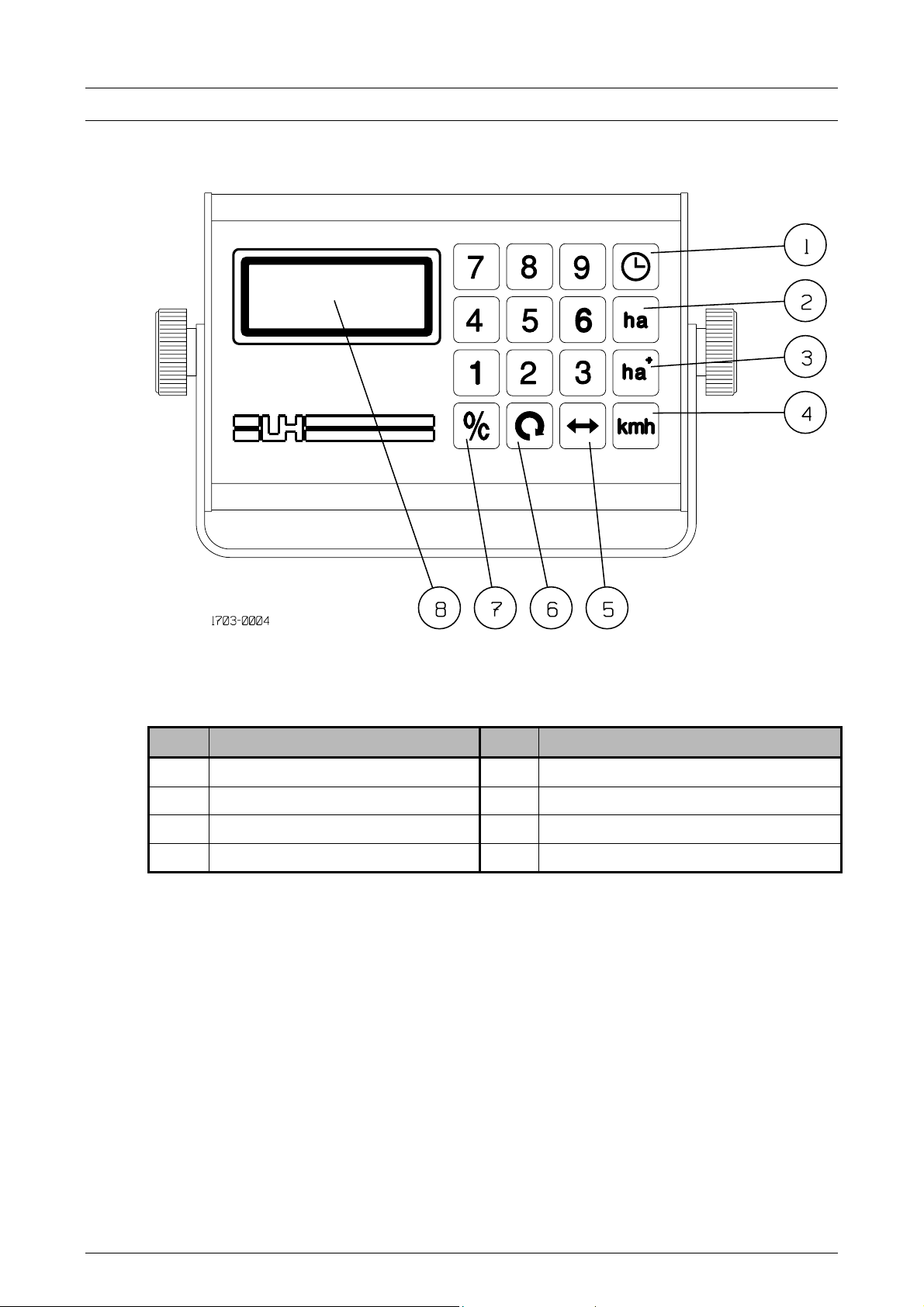
Pos. Description Pos. Description
1 Time functions key 5 Working width encodement
2 Area (trip) 6 Wheel circumference encodement
3 Area (total) 7 Reset key
4 Forward speed 8 Display
LH A
GRO 5
Page 6

ENEREL OPERATION
G
THE LH 1000
The LH 1000 is a very simple monitor to operate, which is able to monitor the
following:
NB! The six functions contained in LH 1000, are arranged in two sets and cannot
! UNITS
All the functions within the selected set of functions are calculated simultaneously.
This means, that you can monitor, e.g. your speed, and at the same time the
monitor counts area and time.
LH 1000 O
be used simultaneously.
Function set 1 Function set 2
! TIME ! TIME
! AREA ! RPM
! FORWARD SPEED ! DISTANCE
PERATORS
ITTING MANUAL
& F
All entered values and gathered data are stored in a memory, if power,
deliberately or not, is cut off.
LH 1000 can be used on the following:
! TRACTORS
! COMBINE HARVESTERS
! MOBILE SPRAYERS
IN FACT ANY AGRICULTURAL MACHINE
!
On the following pages you will find a description of how to encode, use, test and
fit your LH 1000.
SECTION FUNCTION
With this function the working width is divided into four equal sections. This section
function reduces the area measured by the number of sections that have been
switched off. This function works as follows:
! Pressing the numerical key "1" will reduce the working width to 1/4 of the
encoded working width.
! Pressing the numerical key "2" will reduce the working width to 2/4 of the
encoded working width.
! Pressing the numerical key "3" will reduce the working width to 3/4 of the
encoded working width.
Full working width can be achieved manually by pressing the numerical key "4" or
automatically when the implement sensor is activated.
6 LH A
GRO
Page 7

LH 1000 O
PERATORS
ITTING MANUAL
& F
E
ENCODING THE LH 1000 (FUNCTION SET 1)
There are two figures that need to be encoded before the LH 1000 can be used. It
is important that the following are accurate as these are fundamental for correct
operation of the monitor.
WORKING WIDTH
The working width of the implement being used is encoded here:
Step Key Procedure
NCODING THE
LH 1000
1
Press the working width key.
2 Encode the working width in centimetres using the numerical
keys. Ensure that overlaps are accounted for. If the working width
is unknown, then drive 5 bouts and measure the distance between
the first and the last, then divide the distance by 5.
3 The encoded value is stored automatically until another working
width is encoded; press any other key to leave this encodement.
FORWARD SPEED CALIBRATION (WHEEL CIRCUMFERENCE)
To ensure that the LH 1000 can accurately measure forward speed, which is also
used for area calculation, the wheel circumference must be measured and
encoded. The procedure for this is as follows:
WHEEL CIRCUMFERENCE WITH MAGNETS FITTED TO THE WHEEL
Step Key Procedure
1 Make a mark on the field and on the tire on the wheel with
magnets fitted.
2 Drive slowly forward until the wheel has turned 10 times.
3 Make a mark on the field again.
4 Measure the distance between the 2 marks on the field and divide
this distance with 10 the result being the effective wheel
circumference.
5 Divide the effective wheel circumference with the number of
magnets fitted to the wheel.
6
Press the wheel circumference key and an >0< appears on the left
of the display indicating that "wheel circumference" has been
selected.
7 Encode the result (from steps 1 to 5) in centimetres using the
numerical keys.
8 The encoded value is stored automatically until another wheel
circumference is encoded; press any other key to leave this
encodement.
LH A
GRO 7
Page 8

NCODING THE
E
LH 1000 LH 1000 O
PERATORS
Example:
In the following example we assume that we use a tractor with a wheel
circumference of 500 cm and 2 magnets fitted to the wheel:
Measurement shows that the effective wheel circumference = 500.6 cm.
There are 2 magnets fitted so the effective wheel circumference needs to be
divided with 2.
500.6 : 2 = 250.3 cm
Encode this as 250
WHEEL CIRCUMFERENCE WITH A MAGNET FITTED TO CARDAN SHAFT
A magnet can be fitted to the cardinal shaft if, for some reason, it is not possible to
fit any magnets onto a wheel. To determine the value to be entered as the "wheel
circumference" use the following procedure:
Step Key Procedure
ITTING MANUAL
& F
1
Enter a working width of 9999 as described on page 7.
2
Press the area total key.
3 Drive slowly forward until 1 appears on the display STOP
IMMEDIATELY.
4 Make a mark on the field and on the tire.
5 Drive until the display changes from 10 to 11 STOP
IMMEDIATELY.
6 Make a mark on the field again.
7 Measure the distance between the 2 marks on the field. Divide this
distance with 10.
8
Press the wheel circumference key and an >0< appears on the left
of the display indicating that "wheel circumference" has been
selected.
9 Encode the value determined in steps 1 to 7 using the numerical
keys.
10 The encoded value is stored automatically until another wheel
circumference is encoded; press any other key to leave this
encodement.
Remember to encode the correct working width for the implement again!
8 LH A
GRO
Page 9

LH 1000 O
PERATORS
ITTING MANUAL
& F
O
OPERATING THE LH 1000
FUNCTION SET 1
WORK TIME IN HOURS AND MINUTES
Key Function
Pressing this key displays the effective work time (max. 99 hours 59
minutes)
The time counter is started and stopped by pressing the key.
Flashing colon >:< means that the time counter is running.
Constant colon >:< means that the time counter is stopped.
Pressing this key for min. 3 seconds resets the counter.
PERATING THE
LH 1000
AREA TRIP & TOTAL COUNTERS
The area counters start and stop automatically when the implement is in work/not
in work (implement sensor) and continue to count regardless of what other
function in function set 1 has been selected. Area is not being measured if an >r<
is displayed on the screen.
Key Function
Trip counter:
Pressing this key displays the area covered in ha with 2 decimals from 0
to 99.99 ha and with 1 decimal from 100 to 999.9 ha.
Pressing this key for min. 3 seconds resets the counter.
Total counter:
Pressing this key displays the total area covered in ha with 2 decimals
from 0 to 99.99 ha and with 1 decimal from 100 to 999.9 ha.
This function can be used to sum area covered for, i.e. a month.
Pressing this key for min. 3 seconds resets the counter.
FORWARD SPEED
Key Function
Pressing this key displays the present forward speed in kilometres per
hour with 1 decimal.
Forward speed is always displayed when the monitor is switched on.
An “r” on the left-hand side of the display under this function, indicates
that the area override sensor has been activated.
Forward speed is zeroed after approx. 8 second after stopping.
LH A
GRO 9
Page 10

PERATING THE
O
LH 1000 LH 1000 O
FUNCTION SET 2
As mentioned in the introduction, the LH 1000 has 2 function sets. To select
function set 2 a working width of 9999 must be encoded, do as follows:
The following functions are now available:
RPM
Key Function
PERATORS
ITTING MANUAL
& F
Press the shown keys in this order.
Pressing this key displays RPM if the following conditions are met:
! Function set 2 has been selected.
! An RPM sensor is connected to the wheel sensor input.
! There is only 1 magnet fitted per revolution.
UNIT COUNTER
Key Function
Pressing this key displays units counted if the following conditions are
met (one unit is counted each time a magnet passes the sensor):
! Function set 2 has been selected.
! A wheel sensor where units are to be counted has been fitted.
The unit counter can be reset in the same manner as the area total
counter.
DISTANCE COUNTER
Key Function
Pressing this key displays the distance measured in metres if the
following conditions are met:
! Function set 2 has been selected.
! The wheel circumference is encoded in centimetres.
The distance counter can be reset in the same manner as the area trip
counter.
10 LH A
GRO
Page 11

LH 1000 O
PERATORS
ITTING MANUAL
& F
FITTING THE LH 1000
FITTING THE MONITOR
Fit the monitor where it can be easily seen by the operator whilst driving. We
recommend on top of the instrument panel or to the right-hand side of the cabin
above the lift operating handles.
The form supplied with the LH 1000 can be stuck in the cabin so that the noted
values can easily be found and re-entered if necessary.
POWER SUPPLY
The supplied power cable should be connected to 12V so that the monitor is
switched on and off with the ignition (ignition live).
The power cable wires should be connected thus:
F
ITTING THE
LH 1000
Blue = +12V (power)
Brown = 0V (ground)
IMPORTANT! Never incorrectly connect these wires, as the monitor will be
damaged instantly.
GENERAL WIRING
Lead all cables so that they are as protected as possible. Wherever possible lead
the cables alongside existing cables, hydraulic pipes or similar, and fasten with the
supplied cable ties.
Beware of moving parts and heat sources, e.g. exhaust pipes.
Cables in the cab that cannot be hidden should be fastened with adhesive cable
fasteners, clean the surface thoroughly with, i.e. alcohol before sticking the cable
fasteners to the surface.
LH A
GRO 11
Page 12

ITTING THE
F
LH 1000 LH 1000 O
FITTING THE WHEEL SENSOR
We recommend fitting the wheel sensor to the tractors right back wheel. See the
following diagram.
The distance between the magnets and the wheel sensor must not be greater than
5 mm. Fit 2 magnets if the effective wheel circumference is larger than 250 cm.
NOTE! The magnets must be fitted with equal distance otherwise the
displayed forward speed will be erratic.
The magnets can, i.e. be fitted next to the wheel bolts.
Always fit the magnets with the yellow dot facing the sensor.
PERATORS
ITTING MANUAL
& F
12 LH A
GRO
Page 13

LH 1000 O
PERATORS
ITTING MANUAL
& F
F
ITTING THE
LH 1000
The wheel sensor can be fitted to the cardinal shaft on 4-wheel drive machines.
A ”bipolar” sensor must be used when fitting to the cardinal shaft. This sensor
must be ordered separately as it is different than the supplied sensor (see the
following diagram for a typical fitting of a sensor to the cardinal shaft):
LH A
GRO 13
Page 14

ITTING THE
F
LH 1000 LH 1000 O
FITTING THE AREA ON/OFF (IMPLEMENT) SENSOR
Typical fitting of the implement sensor on the tractor’s lift arms:
PERATORS
ITTING MANUAL
& F
The implement sensor can be fitted in other positions (PTO handle, hydraulic
cylinders, other handles, etc.). There must be movement of minimum 50 mm. The
distance between the sensor and the magnet must not exceed 5 mm.
An electrical signal from, i.e. a sprayer switch box, etc. can be used as the
implement signal. The signal must change to 0V (ground), when the implement is
not working.
a. b. c.
+12 V
LIFT UP
SIGNAL
LIFT
ELECTRIC
SPRAYER FITTINGCOMP.
+ 12 V
MAIN SWITCH
SPRAYER ON/OFF
SIGNAL
ELECTRIC
VALVE
+ 12 V
SWITCH
SIGNAL
IMPORTANT! Never connect power (+12V) to the brown output on the LH 1000,
as this will damage the LH 1000.
14 LH A
GRO
Page 15

LH 1000 O
PERATORS
ITTING MANUAL
& F
F
TESTING THE SYSTEM
The sensors & monitor can be tested for correct operation as follows:
Enter a working width of 8888 thus:
The LH 1000 will now display:
"h" each time the wheel sensor is activated.
"r" each time the implement sensor is activated.
Note! "r" will appear when displaying forward speed when the implement sensor
is activated.
ITTING THE
Press the shown keys in this order.
LH 1000
ERROR WARNING
To ensure that data will not be lost, the LH 1000 has a built in error indication:
If your LH 1000 displays this error warning, the supply voltage to the monitor is too
low. Check therefore the power supply to the monitor (both + and -).
LH A
GRO 15
Page 16

LH 1000 O
PERATORS & FITTING MANUAL
NOTES
N
OTES
LH A
GRO 16
 Loading...