

Page 1

Fieldware for The Legacy 6000
Software Version 2.11
LEGACY 6000 CAN BUS
USER GUIDE
Software Version 2.11
98-05053 R1
Midwest Technologies
2864 Old Rochester Road
Springfield, IL 62703
217.753.8424
www.mid-tech.com www.teejet.com
Page 2

Fieldware for The Legacy 6000
Software Version 2.11
Copyrights
© 1999 Midwest Technologies Inc. All rights reserved. No part of this document or the computer programs
described in it may be reproduced, copied, photocopied, translated or reduced in any form or by any means,
electronic or machine readable, recording or otherwise, without prior written consent from Midwest Technologies, Inc.
Trademarks
Unless otherwise noted, all other brand or product names are trademarks or registered trademarks of their
respective companies or organizations.
Limitation of Liability
MIDWEST TECHNOLOGIES, INC. PROVIDES THIS MATERIAL “AS IS” WITHOUT WARRANTY
OF ANY KIND, EITHER EXPRESSED OR IMPLIED. NO COPYRIGHT LIABILITY OR PATENT IS
ASSUMED. IN NO EVENT SHALL MIDWEST TECHNOLOGIES, INC BE LIABLE FOR ANY LOSS
OF BUSINESS, LOSS OF PROFIT, LOSS OF USE OR DATA, INTERUPTION OF BUSINESS, OR FOR
INDIRECT, SPECIAL, INCIDENTIAL, OR CONSEQUENTIAL DAMAGES OF ANY KIND, EVEN IF
MID-TECH HAS BEEN ADVISED OF SUCH DAMAGES ARISING FROM MID-TECH SOFTWARE.
Page 3

Fieldware for The Legacy 6000
Software Version 2.11
Table of Contents
Chapter 1 - System Introduction 1
System Introduction ..................................................................................................... 1-2
System Features .................................................................................................. 1-2
CAN Bus Versatility and Value ................................................................................ 1-3
What is a CAN Bus and why use one? ............................................................... 1-3
Fieldware for the Legacy 6000 .................................................................................1-4
Mid-Tech CAN Bus System Overview ........................................................................ 1-5
The Legacy 6000 Console ........................................................................................ 1-5
Power Speed Module ................................................................................................ 1-6
Inputs .................................................................................................................. 1-6
Inputs/Outputs ..................................................................................................... 1-6
Switch Sense Module ................................................................................................ 1-7
Inputs .................................................................................................................. 1-7
Communication ................................................................................................... 1-7
Switch Function Module ........................................................................................... 1-8
Outputs ................................................................................................................ 1-8
Input .................................................................................................................... 1-8
Communication ................................................................................................... 1-8
Product Control Module ........................................................................................... 1-9
Inputs .................................................................................................................. 1-9
Outputs ................................................................................................................ 1-9
Communication ................................................................................................... 1-9
Swath XL Lightbar ................................................................................................. 1-10
Communication: ................................................................................................ 1-10
CAN Bus Cable Specifications ............................................................................... 1-11
CAN Modules (PCM, SSM, PSM) ......................................................................... 1-11
Cable Harnesses ...................................................................................................... 1-12
Power Speed Module (PSM) ............................................................................ 1-12
Switch Sense Module ........................................................................................ 1-12
Product Control Module .................................................................................. 1-13
Typical Legacy 6000 Configurations ......................................................................... 1-14
Single Channel Liquid Flow Meter ........................................................................ 1-14
Single Channel Granular Spreader ......................................................................... 1-15
Single Channel Liquid with AutoBoom Shutoff (SFM) ......................................... 1-16
Dual Channel with Wet and Dry Booms ................................................................ 1-17
Dual Channel Granular with Two Sensors per Channel ......................................... 1-18
Chapter Notes .............................................................................................................. 1-19
Page 4

Fieldware for The Legacy 6000
Software Version 2.11
Chapter 2 - Getting Started 1
Software Overview ........................................................................................................ 2-2
Powering Up ............................................................................................................. 2-2
Screen Navigation & Selection ................................................................................. 2-3
Standard Pages .......................................................................................................... 2-4
Launcher Page ..................................................................................................... 2-4
Setup Menu Page ............................................................................................... 2-5
Setup Wizard ...................................................................................................................2-5
Setup Sub-Groups ........................................................................................................... 2-5
Exiting a Setup Menu Page ............................................................................................. 2-5
Data Entry Page ........................................................................................................ 2-6
Pick List Data Entry ........................................................................................................ 2-6
Alpha/Numeric Data Entry ............................................................................................. 2-6
System Setup ................................................................................................................. 2-7
Console Setup ................................................................................................................ 2-8
Lightbar Setup .............................................................................................................. 2-9
GPS Receiver Setup .................................................................................................... 2-10
Implement Setup ......................................................................................................... 2-11
The Vehicle Coordinate System ............................................................................. 2-11
The X and Y Axes ............................................................................................ 2-11
Location of GPS Antenna ................................................................................. 2-11
Swaths and Sections .......................................................................................... 2-11
Entering the Implement Width ............................................................................... 2-13
Number of Swaths Page .......................................................................................... 2-14
Entering the Number of Sections in a Swath .......................................................... 2-14
Setting the Section to Switch Assignment .............................................................. 2-15
Entering the Section Width ..................................................................................... 2-15
Entering the Offset Direction Y .............................................................................. 2-16
The Offset Distance Y ............................................................................................ 2-16
Entering the Offset Direction X .............................................................................. 2-17
Setting the PCM Assignment .................................................................................. 2-18
Completing Implement Setup ................................................................................. 2-19
Product Control Module (PCM) Setup ..................................................................... 2-20
Selecting a PCM Setup Favorite ............................................................................. 2-22
Setting the Application Type .................................................................................. 2-24
Application Type Options ................................................................................. 2-24
Application Type Settings ............................................................................... 2-25
Setting the Drive Type ............................................................................................ 2-26
Drive Type Settings ......................................................................................... 2-27
Calculating the Prime Value .........................................................................................2-27
Setting the Units ...................................................................................................... 2-29
Selecting the Primary Sensor .................................................................................. 2-30
Page 5

Fieldware for The Legacy 6000
Software Version 2.11
Primary Sensor Settings ................................................................................... 2-31
Selecting the Secondary Sensor .............................................................................. 2-33
Secondary Sensor Settings ............................................................................... 2-34
Selecting a Monitor ................................................................................................. 2-36
Monitor Settings .............................................................................................. 2-37
Finishing the PCM Setup ........................................................................................ 2-39
Saving the PCM Setup to a File ....................................................................... 2-40
Chapter Notes .............................................................................................................. 2-41
Chapter 3 - Real-time Setup 1
Operation Overview ..................................................................................................... 3-2
Starting a Job ................................................................................................................ 3-4
Creating a New Job ................................................................................................... 3-4
Selecting an Existing Job .......................................................................................... 3-4
Creating a Job Based on an Existing Job .................................................................. 3-4
Manually Naming a Job ...................................................................................... 3-5
Automatically Naming a Job .............................................................................. 3-5
No PCMCIA Card Setup .......................................................................................... 3-6
ARM Launcher ............................................................................................................. 3-7
No PCMCIA Card Setup .......................................................................................... 3-7
Performing a Calibration ............................................................................................. 3-8
Introduction ............................................................................................................... 3-8
The Common Calibration Procedure ........................................................................ 3-8
Distance/Speed Calibration ....................................................................................... 3-9
Distance/Speed Calibration Continued ............................................................. 3-10
Liquid Flow Static Calibration ............................................................................... 3-11
Liquid Flow Static Calibration / Continued ...................................................... 3-12
Liquid Flow In-Field Calibration ............................................................................ 3-13
Liquid Flow In-Field Calibration Continued .................................................... 3-14
Granular & Seeder Static Calibration ..................................................................... 3-15
Granular & Seeder Static Calibration / Continued ........................................... 3-16
Granular & Seeder In-Field Calibration ................................................................. 3-17
Granular & Seeder In-Field Calibration Continued .......................................... 3-18
Pressure Calibration ................................................................................................ 3-19
Pressure Calibration / Continued ..................................................................... 3-20
NH3 In-Field Calibration ........................................................................................ 3-21
NH3 In-Field Calibration Continued ................................................................ 3-22
Injection Static Calibration ..................................................................................... 3-23
Prime Injection System .............................................................................................. 3-25
1. Calculate Prime value ................................................................................... 3-25
2. Setup System for Priming ............................................................................ 3-26
3. Start Prime .................................................................................................... 3-26
Page 6

Fieldware for The Legacy 6000
Software Version 2.11
Reverse Prime Injection System ................................................................................ 3-27
1. Setup Stem for Reverse Priming .................................................................. 3-28
2. Start Reverse Prime ...................................................................................... 3-28
Job Report Setup ........................................................................................................ 3-29
No PCMCIA Card Selected .............................................................................. 3-29
Running the Job Report Wizard ........................................................................ 3-29
Job Report Detailed Description ............................................................................. 3-30
ARM Setup .................................................................................................................. 3-31
No PCMCIA Card Selected .............................................................................. 3-31
Running the ARM setup Wizard ...................................................................... 3-31
ARM Setup Detailed Description ........................................................................... 3-32
Auto Boom Shutoff (Section Center) ..................................................................... 3-33
Enter a Record, Boundary, Guideline, or Map File Name ..................................... 3-34
Product Setup .............................................................................................................. 3-35
Running the Product Setup Wizard .................................................................. 3-35
Product Setup Detailed Description ........................................................................ 3-36
The Select PCM Page ............................................................................................. 3-37
Select the Product Name ......................................................................................... 3-38
Selecting a Product from the Products Database ..........................................................3-38
Favorites ........................................................................................................................ 3-38
New Product ................................................................................................................. 3-38
Variable Rate Application ...................................................................................... 3-39
Selecting Prescription Map ............................................................................... 3-39
Single Product Variable Rate Prescription Map ............................................... 3-39
Multiproduct Variable Rate ............................................................................. 3-40
Prescription Map for Each Product ............................................................................... 3-40
One Prescription Map for All Products ........................................................................ 3-41
Select the Prescription Map Layer .................................................................... 3-42
Chapter Notes .............................................................................................................. 3-43
Chapter 4 - Real-time Operation 1
Product Application ...................................................................................................... 4-2
Real-time pages ......................................................................................................... 4-2
Information Pages .....................................................................................................4-3
Rate Pages ........................................................................................................... 4-3
GPS / Boundary Page ......................................................................................... 4-3
Adjusting the Product Application Rate ............................................................ 4-4
Manual Control ................................................................................................... 4-4
Test Speed ........................................................................................................... 4-5
Reset Initial Quantity ......................................................................................... 4-5
Information Page Soft Keys Descriptions ......................................................... 4-6
The Map Page ........................................................................................................... 4-7
Page 7

Fieldware for The Legacy 6000
Software Version 2.11
Real-time Map Page Soft-key Descriptions ........................................................ 4-8
System, Warning and Error Messages .................................................................... 4-11
System Message ................................................................................................ 4-11
Warning Message ............................................................................................. 4-11
Error Message .................................................................................................. 4-12
Real-time Guidance Operation .................................................................................. 4-13
Starting Guidance ............................................................................................. 4-13
Changing Guidance Pattern .............................................................................. 4-13
The Straight-Line Guidance Pattern ....................................................................... 4-14
Mark Point A .................................................................................................... 4-14
Mark Point B ..................................................................................................... 4-14
The Headland Guidance Pattern ............................................................................. 4-15
Applying Multiple Headland Circuits ............................................................... 4-15
Headland Pattern Example ............................................................................... 4-16
Switching from Headland to Straight-line A-B Pattern ................................................ 4-17
The Ignore Headland Guidance Pattern .................................................................. 4-19
Ignore Headland Pattern Example .......................................................................... 4-20
Step 1: Start Applying Headlands ..................................................................... 4-20
Step 2: Select Headland Off Mode ................................................................... 4-20
Step 3: Establish First Interior Pass ................................................................. 4-21
Step 4: Ignore Headland Data ........................................................................... 4-21
If you forgot to start a headland, you can: .................................................................... 4-22
The Circle Pivot Pattern .......................................................................................... 4-23
Circle Pivot Example ....................................................................................... 4-24
Marking Point A ........................................................................................................... 4-24
Marking Point B ............................................................................................................ 4-24
Driving in the Circle Pivot Pattern ............................................................................... 4-25
Lightbar Curved Guidance Graphics ....................................................................... 4-27
Applied Area Detection .............................................................................................. 4-28
Detecting A Previously Applied Area .................................................................... 4-28
Detecting Neighboring Swath ................................................................................. 4-28
Mapping a Field Boundary ........................................................................................ 4-30
Closing or Pausing the Boundary Mapping Process ......................................... 4-30
Mapping Points and Hazards .................................................................................... 4-32
Marking a Point ................................................................................................ 4-32
Marking a Hazard ............................................................................................ 4-33
Object Name File .............................................................................................. 4-33
Exiting Real-Time Operation .................................................................................... 4-34
Fieldware-Map Manager ......................................................................................... 4-34
Lightbar Index ............................................................................................................ 4-35
Data Transfer and Report Generation ..................................................................... 4-38
Page 8

Fieldware for The Legacy 6000
Software Version 2.11
Chapter Notes .............................................................................................................. 4-39
Chapter 5 - System Tools 1
System Tools .................................................................................................................. 5-2
Device Manager ........................................................................................................ 5-3
CAN Bus ............................................................................................................. 5-3
GPS Receiver ..................................................................................................... 5-4
LightBar .............................................................................................................. 5-4
Lightbar SoftKeys and Description ................................................................................ 5-4
PCM, SSM, and PSM ........................................................................................ 5-5
PCM, SSM, & PSM SoftKeys and Description .............................................................. 5-5
Console .............................................................................................................. 5-6
Console SoftKeys and Description .................................................................................5-6
Backing up Console System Files ...................................................................... 5-7
Required Items: ............................................................................................................... 5-7
Restoring Console System Files ......................................................................... 5-7
Importing Object Name Files into Console Memory ........................................ 5-8
Card Manager ........................................................................................................... 5-9
Card Manager SoftKeys and Description ....................................................................... 5-9
Chapter Notes .............................................................................................................. 5-11
Chapter 6 - Running Mapper 1
Mapper Introduction .................................................................................................... 6-2
Starting Mapper ........................................................................................................ 6-2
Starting a Job ............................................................................................................ 6-3
Creating a New Job ............................................................................................. 6-3
Selecting an Existing Job .................................................................................... 6-3
Creating a Job Based on an Existing Job ............................................................ 6-3
Manually Naming a Job ..................................................................................... 6-4
Automatically Naming a Job .............................................................................. 6-4
Mapper Setup ..................................................................................................... 6-5
Mapper Setup and Operation Steps ................................................................................ 6-5
Mapper Setup ..................................................................................................... 6-6
Road Markers ..................................................................................................... 6-7
Enter Road Marker Name ............................................................................................... 6-8
Creating Object Name .............................................................................................. 6-9
Creating New Object Name ................................................................................ 6-9
Real-time pages ....................................................................................................... 6-10
Map page ........................................................................................................... 6-10
Map Page Soft Keys Descriptions .................................................................... 6-11
Information Page .............................................................................................. 6-13
Information Page SoftKeys and Description .................................................... 6-13
Mapper Tools .............................................................................................................. 6-14
Page 9

Fieldware for The Legacy 6000
Software Version 2.11
The Options Menu ........................................................................................... 6-16
Exiting Real-Time Operation .................................................................................... 6-17
Map Manager .......................................................................................................... 6-17
Chapter Notes .............................................................................................................. 6-18
Appendix A - PCM Favorites Settings ....................................................................... A-1
Appendix B - Creating a Calibration Table ...............................................................B-1
Creating a Calibration Table on a PC .......................................................................B-1
Loading Calibration Table in Legacy 6000 ..............................................................B-2
Using the Calibration Table ......................................................................................B-3
Creating a Calibration Table Using the Legacy 6000 ...............................................B-4
Appendix C - NH3 Application ................................................................................... C-1
NH3 Application Cal# ..............................................................................................C-1
Density for NH3 and Actual N .................................................................................C-1
Example: .............................................................................................................C-1
Notes ........................................................................................................................ C-2
Page 10

Fieldware for The Legacy 6000
Software Version 2.11
Page 11
Chapter 1 - System Introduction
An introduction to the Legacy 6000 System.
Software Version 2.11
Midwest Technologies IL, LLC
Fieldware for the Legacy 6000
Page 12

Fieldware for The Legacy 6000
Software Version 2.11
System Introduction
The Legacy 6000 system allows the control of all product types, plus GPS mapping, guidance, and
data collection in a single console. Replacing multiple consoles in the cab with one robust system,
Mid-Tech's Legacy 6000 sets a new standard for control systems of the future.
The Legacy 6000 runs Fieldware software in a Windows CE environment, an extremely dependable and stable operating system. Operation is intuitive with on-screen menu choices and
prompts. An on-board help menu is built in. The heart of the Legacy console is an Intel processor
operating at 206 Megahertz for maximum efficiency.
System Features
System features include:
• Product control with optional integrated guidance
• Four guidance modes, Ignore Headland, Curved, Parallel and Center Pivot.
• Single console in the cab with a single cable connection to the console
• Simplifies operation of product control and GPS record keeping
• Works with Mid-Tech's Swath XL lightbar
• Comes fully loaded with “Fieldware for the Legacy 6000” software
• Precise control of liquid & dry products on common delivery systems
• Flow- or pressure-based liquid control with multiple sensor inputs for each product
• Handles up to 20 individual boom sections and 4 swaths
• Up to 5 application rates per product can be preset and accessed on the go
• Supports granular application control using 2 rate sensors per product
• Compatible with most sensors, valves, and D.C. drives
• Operates bi-directional or PWM valves
• Operator selectable gain settings for control valves
• Adding additional product control is easy
• Single high speed bus cable coming into cab
• Automatic Boom shutoff
• Mapper option for mapping points, lines, and po lyg o ns
1-2 Chapter 1 - System Introduction
System Introduction
Page 13

Fieldware for The Legacy 6000
Software Version 2.11
CAN Bus Versatility and Value
The Legacy 6000 utilizes CAN Bus technology, a new industry standard, which Mid-Tech us es to
execute precise product contr ol in an env iro nm e nt mor e rob ust tha n an y of its predecessors.
What is a CAN Bus and why use one?
Controller Area Network (CAN) is a system comprised of independent, intelligent modules connected by a single high-speed cable, known as a bus, over which all the data in the system travels.
CAN was originally developed for the automotive industry to provide a cost effective means for a
large number of electronic functions or systems to be interconnected without large, expensive and
troublesome wiring harnesses.
Within a CAN system, each module contains its own microprocessor. All modules share a standard protocol or communication sequence, which conforms to the ISO 11898 standard. Since
modules have built-in computing power, a CAN system is extremely flexible and easily expands to
meet a customer's needs.
Individual modules have a specific and unique function to execute, as well as the responsibility to
constantly report that function and its current status. Data on the CAN is available many times a
second allowing the operation of a very fast, responsive control system.
The Legacy 6000 uses 5 types of modules, each having a unique function. Each described in
more detail below. The console in the cab is one of these modules and serves as the user interface. The remaining modules are positioned around the chassis close to the area they influence.
For instance, the Product Control Mo dule (PCM) con nects to the actuator and senso r and controls
the actual release of the product. To upgrade from one-product to three-product application (or
more) is simply a matter of adding additional PCM's to the system.
Chapter 1 - System Introduction 1-3
System Introduction
Page 14

Fieldware for The Legacy 6000
Software Version 2.11
Fieldware for the Legacy 6000
Plug any standard submeter GPS receiver and Mid-Tech's CAN based Swath XL lightbar into the
Legacy 6000 system, and enjoy straight-line, curved or center pivot guidance at your command.
Application maps can be viewed on the Legacy 6000 display as you apply. Cross track error , ar ea
applied, application rates, and other vital information display on the Swath XL lightbar in real time.
Features of Mid-Tech's Fieldware software, developed specifically for the Legacy 6000, include:
• Application Rate Management - permits precise fixed or variable rate application.
• Extensive Product Control Module setup.
• Full system calibration including, granular, liquid, liquid injection and distance.
• CAN Bus, GPS receiver and lightbar diagnostics.
• Create application jobs keeping track of customer, weather and product information.
• Large product database with over 4000 entries co ntaining product name, formulation , and EP A
number.
• Integrated guidance using straight line, h eadland , or center pivo t modes, p lus text repor ting to
the lightbar, in one easy to use format.
• Report generation - full application report s and map s can be generated in Field ware Map Manager PC software at the end of the day. An application report contains a map of the application, customer information, product information, as well as weather, field, and soil conditions.
1-4 Chapter 1 - System Introduction
System Introduction
Page 15

Fieldware for The Legacy 6000
Software Version 2.11
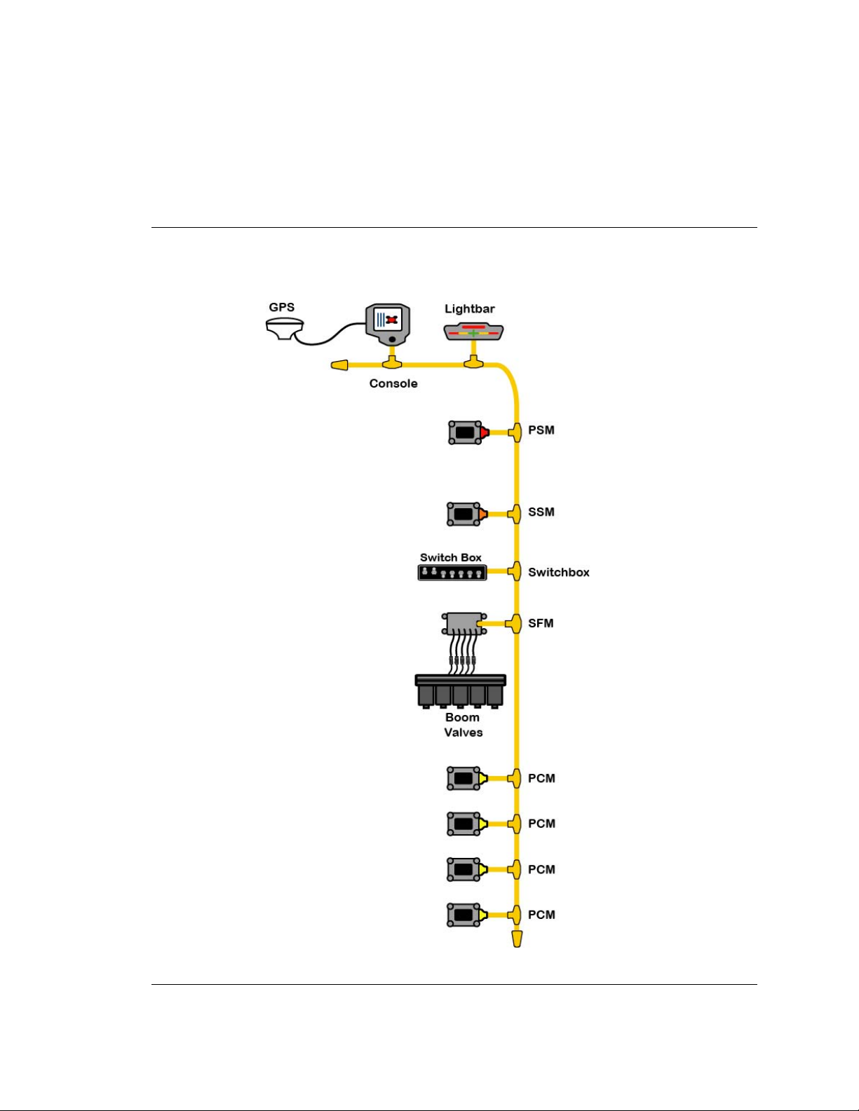
Mid-Tech CAN Bus System Overview
The Mid-Tech CAN bus system is comprised of several components (modules). The Console, the
Power Speed Module (PSM), the Switch Sense Module (SSM), a Product Control Module (PCM),
and a Lightbar . At a minimum, four of these modules ar e required to have a fully functional Legacy
6000 single product control system. The lightbar is optional. T o control m ore than one product, you
will need to add an additional PCM for each additional product you choose to control.
The Legacy 6000 Console
Dimensions: 8.0" Wide x 7.7" High x 4.5" Deep (203 x 196 x 114 mm)
Weight: 2.3 lbs. (1.0 kg)
Enclosure: High impact plastic; back lighted, tactile feed-back switches on front panel
Operator Interface: Back lighted, tactile feed-back switches on front panel
Display: 5.7" diagonal (120 x 90 mm), transflective, QVGA with CCFL back lighting. Brightness
and contrast controlled by switches on the front panel of the console.
Communication: CAN, 29 bit ID, 250K baud, Mid-Tech proprietary messages, Serial RS 232 (2),
USB: (1)
Memory: 64 Mbytes DRAM, 32 Mbytes Flash
Microprocessor: 32-bit Intel StrongARM, SA 1110 with SA 1111 companion chip. 206 MHz.
Drives: PCMCIA type II, single slot
Operating System: Microsoft Windows CE 3.0
Power Requirement: 9 to 16 volts DC
Connector: Sealed, 31 pin Deutsch
GPS Receiver Compatibility: Comp atible with any differentially corrected submeter GPS (DGPS)
receiver which outputs NMEA 0183 at 2 to 10 Hz.
Alarm: Audible alarm
Other:
* Real-time clock with battery back-up
* Simple, yet versatile, RAM mounting system.
Chapter 1 - System Introduction 1-5
Mid-Tech CAN Bus System Overview
Page 16
Fieldware for The Legacy 6000
Software Version 2.11
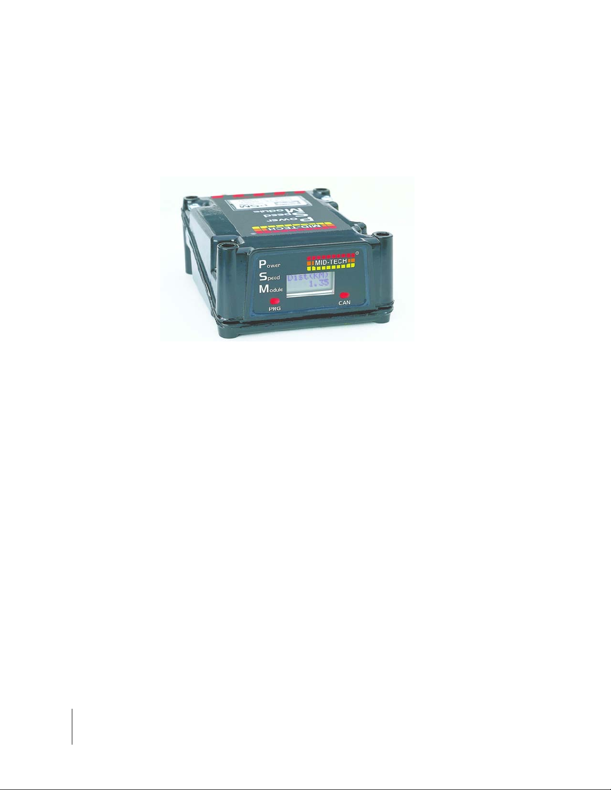
Power Speed Module
The Power Speed Module ( PSM) is the primary arbitrator of the Bus. This module includes the
input point for the speed sensor, the input for power for the CAN bus, a gateway to communicate
with a parallel CAN bus and provides a fully functional RS-232 port as alternative I/O.
Figure 1-1: Power Speed Module
Inputs
Speed 1: digital, 0-12 VDC, optimized for 50% duty cycle, 0-5 KHz, primary input
Speed 2: digital, 0-12 VDC, optimized for 50% duty cycle, 0-5 KHz, secondary input
Ignition sense: digital, 0-16 VDC, (Hi state is ON)
Battery Power: 0-16 VDC
Inputs/Outputs
Mid-Tech CAN: ISO 11898 (Bosch 2.0B), 29 bit ID, 250K baud, Mid-Tech proprietary messages
Gateway CAN: ISO 11898 (Bosch 2.0B), 29 bit ID, 250K baud, Mid-Tech proprietary messages
Serial RS 232: TXD, RXD, RTS, CTS and ground.
1-6 Chapter 1 - System Introduction
Mid-Tech CAN Bus System Overview
Page 17
Fieldware for The Legacy 6000
Software Version 2.11
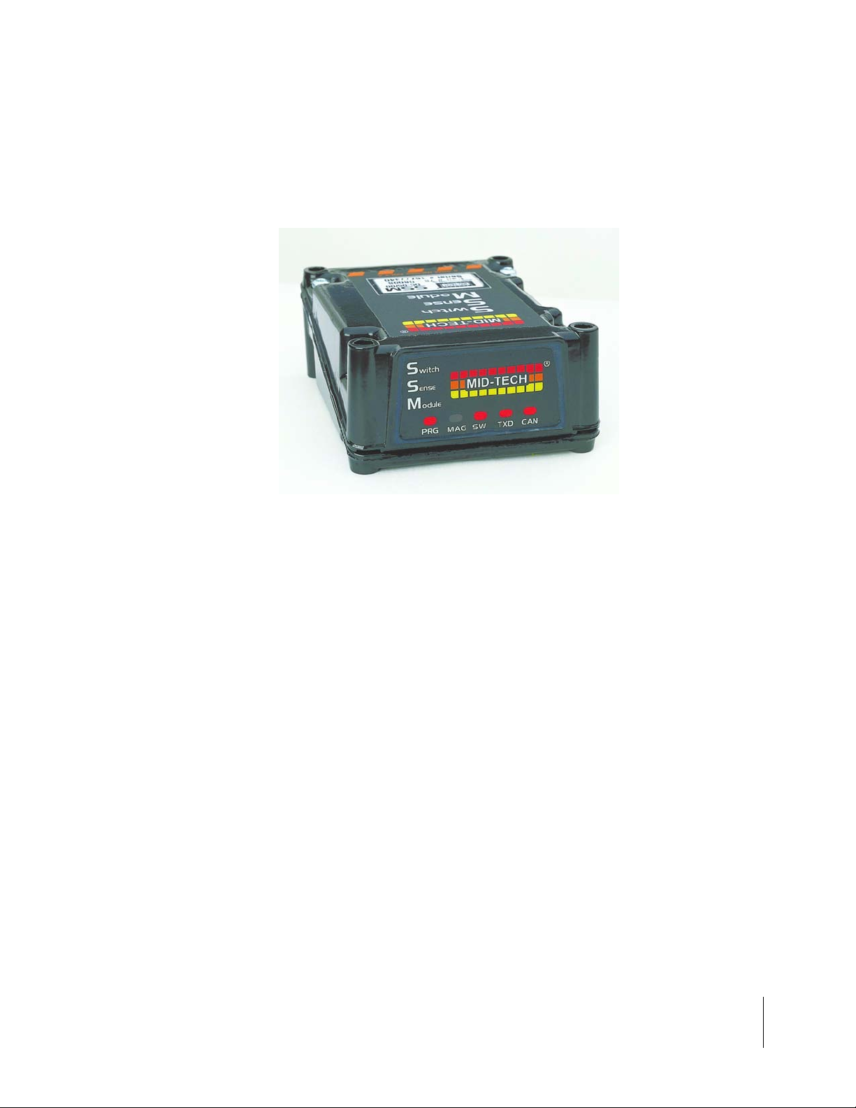
Switch Sense Module
The Switch Sense Module (SSM) senses the status of switches aboard the machine and transforms the switch state into messages meaningful to the CAN Bus.
Figure 1-2: Switch Sense Module (SSM)
Inputs
Booms inputs: up to 20, digital, 0-12 VDC, HI/LO sensing
Ground Speed Override (GSO):1 input, digital, 0-12 VDC, HI/LO sensing
Machine status: 1 input, digital, 0-12 VDC, HI/LO sensing
Communication
Mid-Tech CAN: 29 bit ID, 250K baud, Mid-Tech proprietary messages
Chapter 1 - System Introduction 1-7
Mid-Tech CAN Bus System Overview
Page 18
Fieldware for The Legacy 6000
Software Version 2.11
Switch Function Module
The Switch Function Module (SFM) enables automated system control of boom sections.
Figure 1-3: Switch Function Module (SFM)
Outputs
Booms outputs: (10) 3amp +12switched
Output Connector: A - Ground, B - N/C, C - +12 Open, D - +12 Constant
Input
Battery Power: 30amp
Communication
Mid-Tech CAN: ISO 11898 (Bosch 2.0B), 29 bit ID, 250K baud, Mid-Tech proprietary messages
1-8 Chapter 1 - System Introduction
Mid-Tech CAN Bus System Overview
Page 19
Fieldware for The Legacy 6000
Software Version 2.11
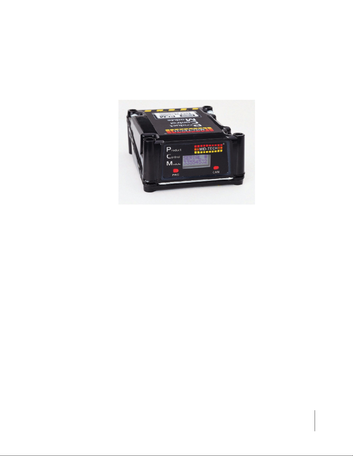
Product Control Module
The Product Control Module (PCM) performs the actual control function for th e Mid-Tech CAN Bus
and connects the actuator and sensor. Control outputs can be bi-directional. One PCM is required
for each product you wish to control.
Figure 1-4: Product Control Module
Inputs
Digital sensor: 4 inputs, digital, 0-12 VDC, 0-5 KHz
Analog sensor: 2 inputs, analog, 0-5 VDC. One of these input s can be converted to a 4-20 ma sen-
sor input by software command.
Battery: 1 Battery Power for the actuator outputs, 12-24 VDC, 10 amp
Outputs
Actuator: 2 outputs, 0-12 VDC, 5 amp each
Regulated: 1 output, 11 VDC, 3 amp
Switched: 1 output, 12 VDC, 5 amp
Sensor power: 3 outputs, 12 VDC, 300 mA total
Communication
Mid-Tech CAN: ISO 11898 (Bosch 2.0B), 29 bit ID, 250K baud, Mid-Tech proprietary messages
Serial: Asynchronous RXD and TXD only
Chapter 1 - System Introduction 1-9
Mid-Tech CAN Bus System Overview
Page 20
Fieldware for The Legacy 6000
Software Version 2.11
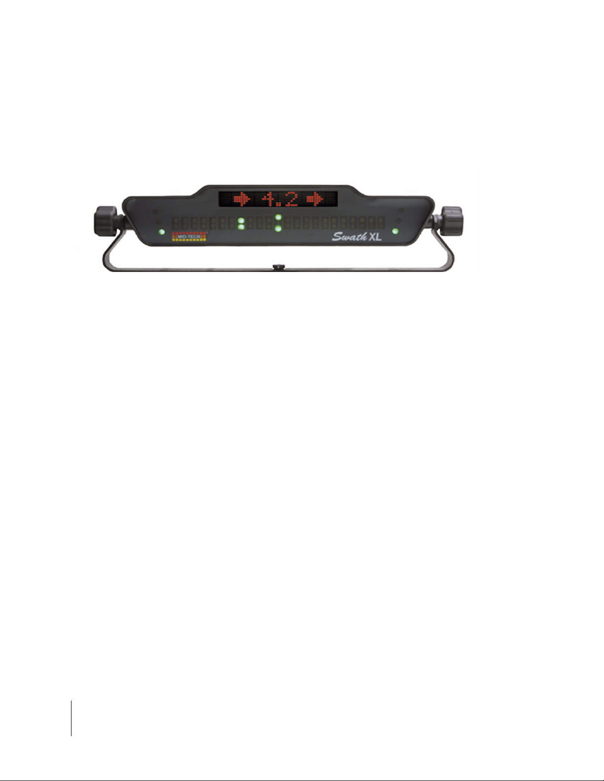
Swath XL Lightbar
A CAN based Swath XL Lightbar was developed specifically for the Legacy 6000 system. The
Lightbar is required for applications using guidance and recommende d for non-guidance uses as
well. In non-guidance use (logging data only) the lightbar can provide area and rate feed back.
Figure 1-5: Swath XL Lightbar
Dimensions: 16.0" Wide x 3.0" High x 3.0” Deep (405 x 76 x 76 mm)
Weight: 8 oz. (0.22 kg)
Enclosure: ABS / Poly carbonate alloy construction. Can be mounted to the exterior of the vehicle.
Cable: Mid-Tech proprietary CAN Bus cable. Cable extension available.
Front Panel LEDs: High-lumen red, yellow and green, adjustable brightness.
Text Display: 8-character, high intensity LED alphanumeric text display, brightness adjustment.
Mounting Bracket: Can be mounted on dash, from ceiling, interior or exterior with large easy to grip
knobs.
Communication:
Mid-Tech CAN: ISO 11898 (Bosch 2.0B), 29 bit ID, 250K baud, Mid-Tech proprietary messages
1-10 Chapter 1 - System Introduction
Mid-Tech CAN Bus System Overview
Page 21
Fieldware for The Legacy 6000
Software Version 2.11
CAN Bus Cable Specifications
5-wire cable with molded connectors. Male or female terminator required on each end.
Pin 1: Ground
Pin 2: +12V
Pin 3: Reserved
Pin 4: CAN High
Pin 5: CAN Low
Speed: 250k baud message update
Module Processor: Siemens C167
Module CAN interface: Siemens 82C250
Message Protocol: ISO 11898 (Bosch 2.0B), 29 bit ID, 250K baud, Mid-Tech proprietary messages
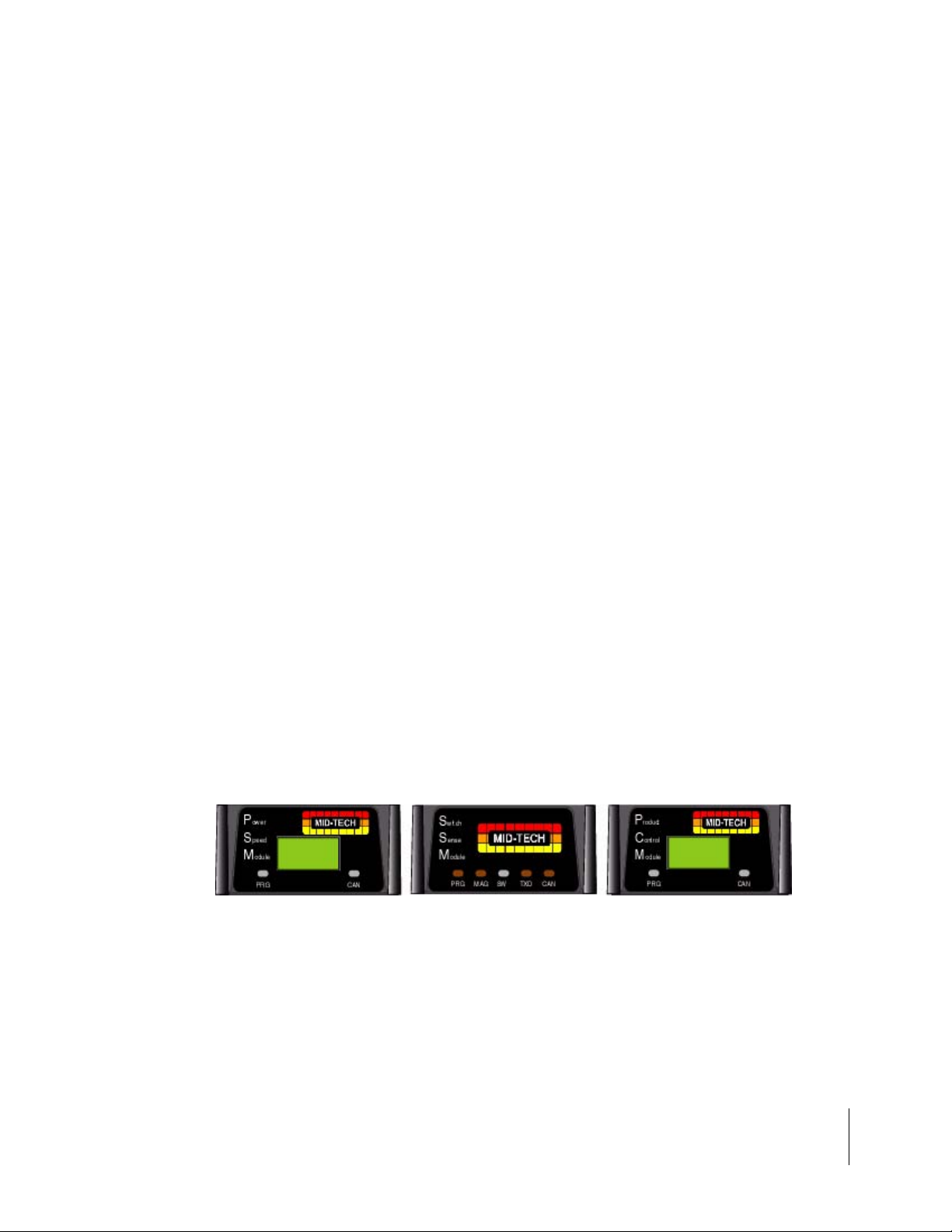
CAN Modules (PCM, SSM, PSM)
Dimensions: 4.7" W x 2.3" H x 6.0" D (120 x 60 x 150 mm)
Weight: 1.9 lbs. (0.9 kg)
Materials: Powder coated cast aluminum
Figure 1-6: CAN Modules
Chapter 1 - System Introduction 1-11
Mid-Tech CAN Bus System Overview
Page 22
Fieldware for The Legacy 6000
Software Version 2.11
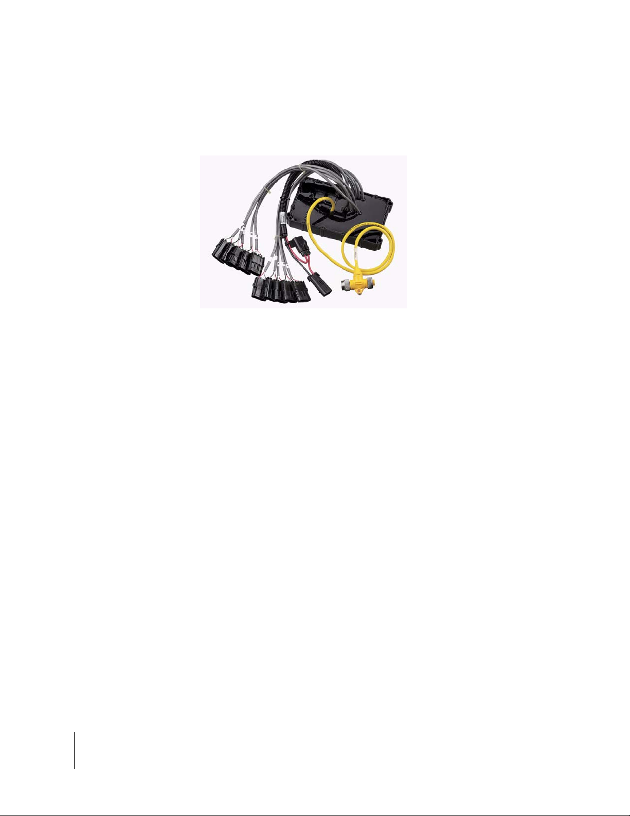
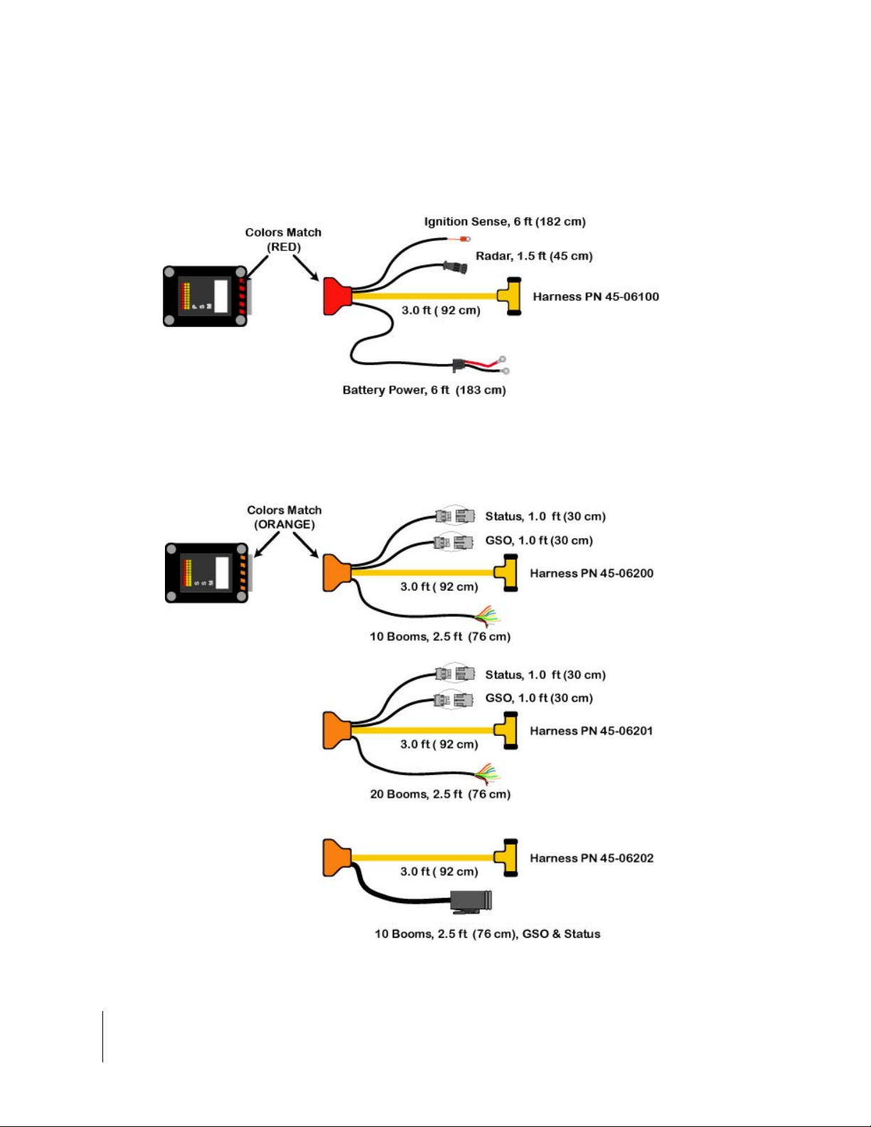
Cable Harnesses
Power Speed Module (PSM)
Figure 1-7: Power Speed Module Harness
Switch Sense Module
Figure 1-8: Switch Sense Module Harness Options
1-12 Chapter 1 - System Introduction
Mid-Tech CAN Bus System Overview
Page 23
Fieldware for The Legacy 6000
Software Version 2.11
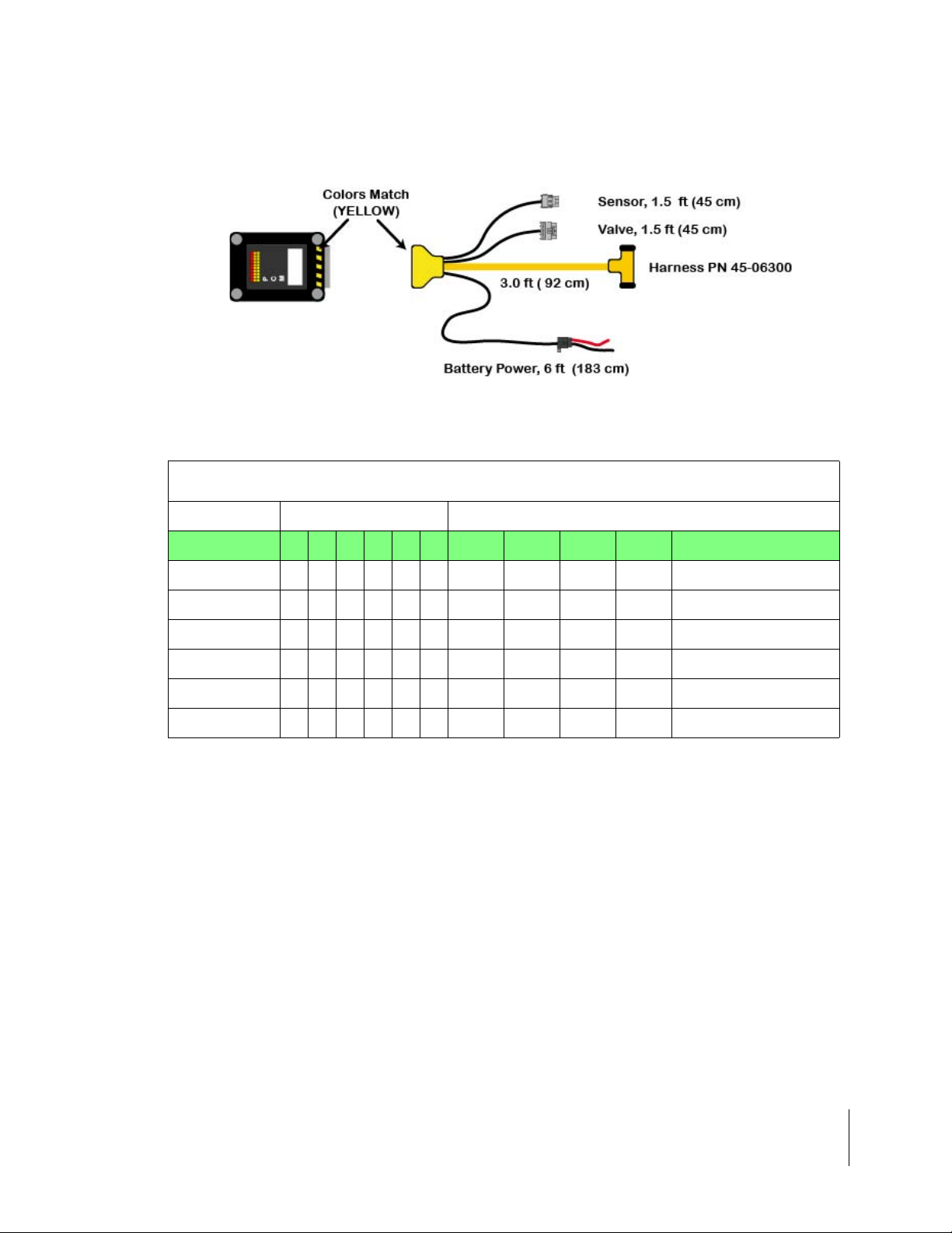
Product Control Module
Figure 1-9: Power Control Module Harness
Sensor Inputs
PCM Cable Options
Part Number A B C D E F CAN PWR Valve Sen. Description
45-06300 X X X X 1 Single Sensor
45-06301 X X X X X 2 Single Sensor w/rpm
45-06302 X X X X X X 3 Dual Sensor w/rpm
45-06303 X X X X X 2 Single Sensor w/press
45-06304 X X X X 1 Pressure Control Single
45-06305 X X X X X 2 Pressure Control, Dual
Table 1-1: PCM Cable Options
NOTE: These cable configurations are available as of 1/1/03. Contact Mid-Tech Customer Service
for other specific sensor or I/O options.
Chapter 1 - System Introduction 1-13
Mid-Tech CAN Bus System Overview
Page 24
Fieldware for The Legacy 6000
Software Version 2.11
Typical Legacy 6000 Configurations
The following schematics reflect some typical Legacy 6000 configurations. Due to the variety of
possible configurations, these schematics should be used for general reference. Contact Midwest
Technologies or your dealer for detailed information regarding your specific configuration and
installation.
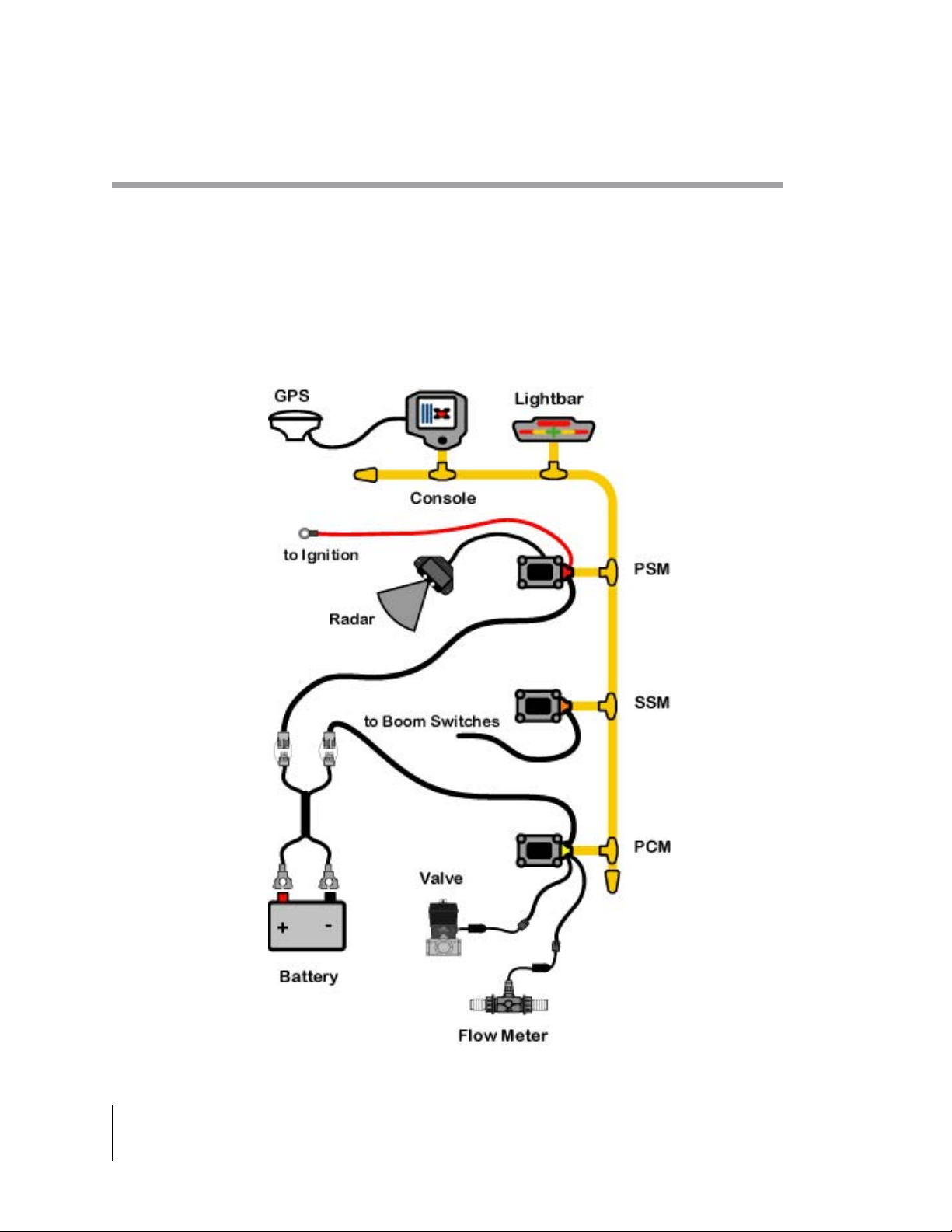
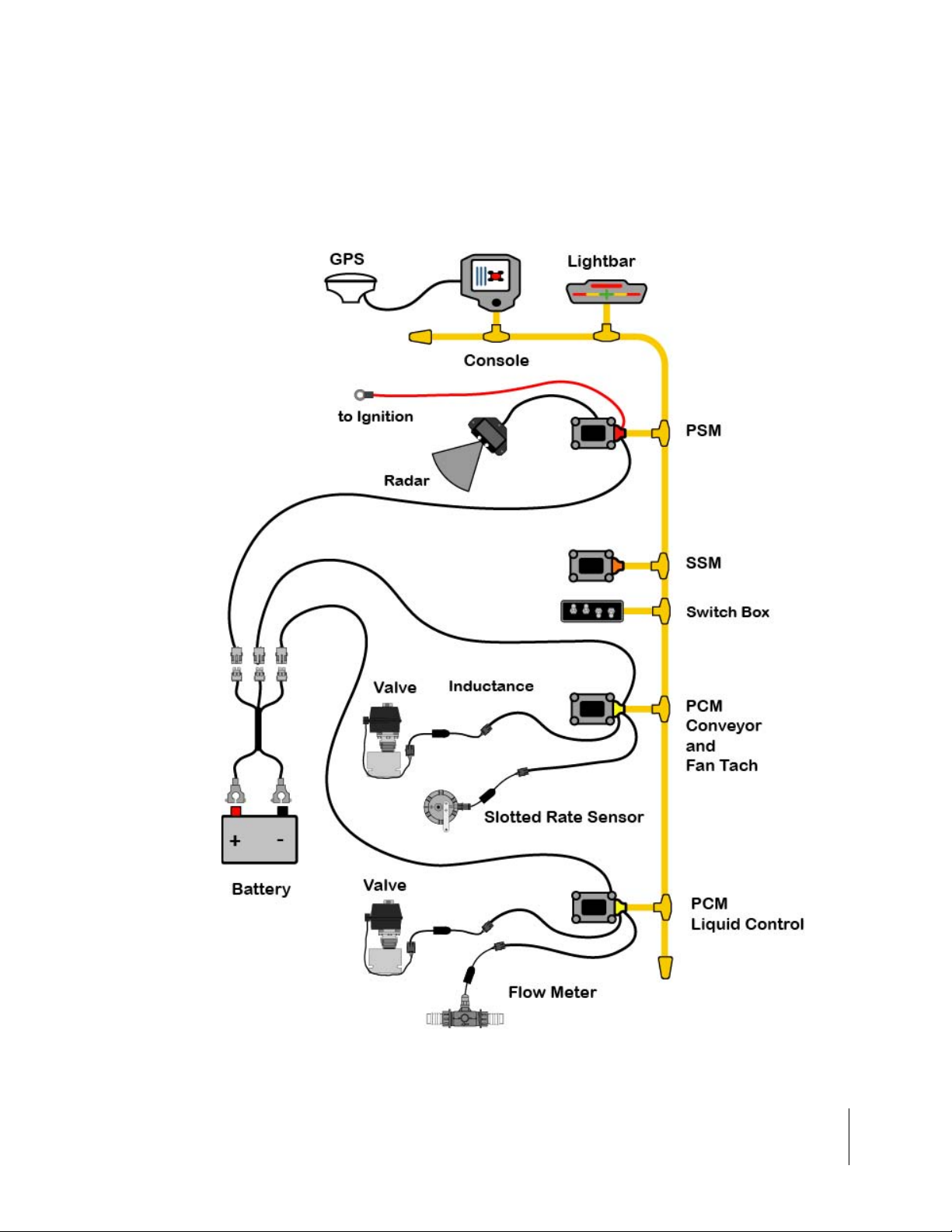
Single Channel Liquid Flow Meter
Figure 1-10: Single Channel Liquid Flow Meter Configuration
1-14 Chapter 1 - System Introduction
Typical Legacy 6000 Configurations
Page 25
Fieldware for The Legacy 6000
Software Version 2.11
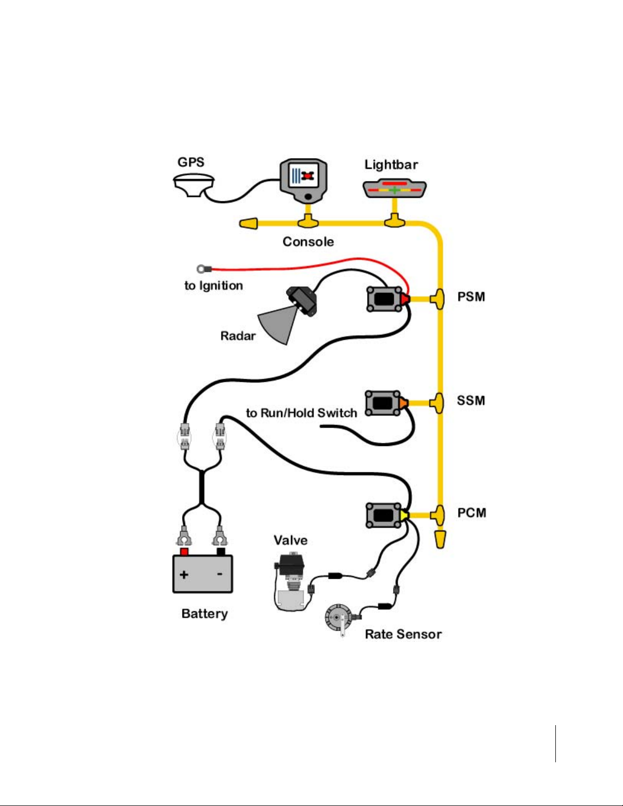
Single Channel Granular Spreader
This is a typical single product granular configuration with spreader control.
Figure 1-11: Single Channel Granular Spreader Configuration
Chapter 1 - System Introduction 1-15
Typical Legacy 6000 Configurations
Page 26
Fieldware for The Legacy 6000
Software Version 2.11
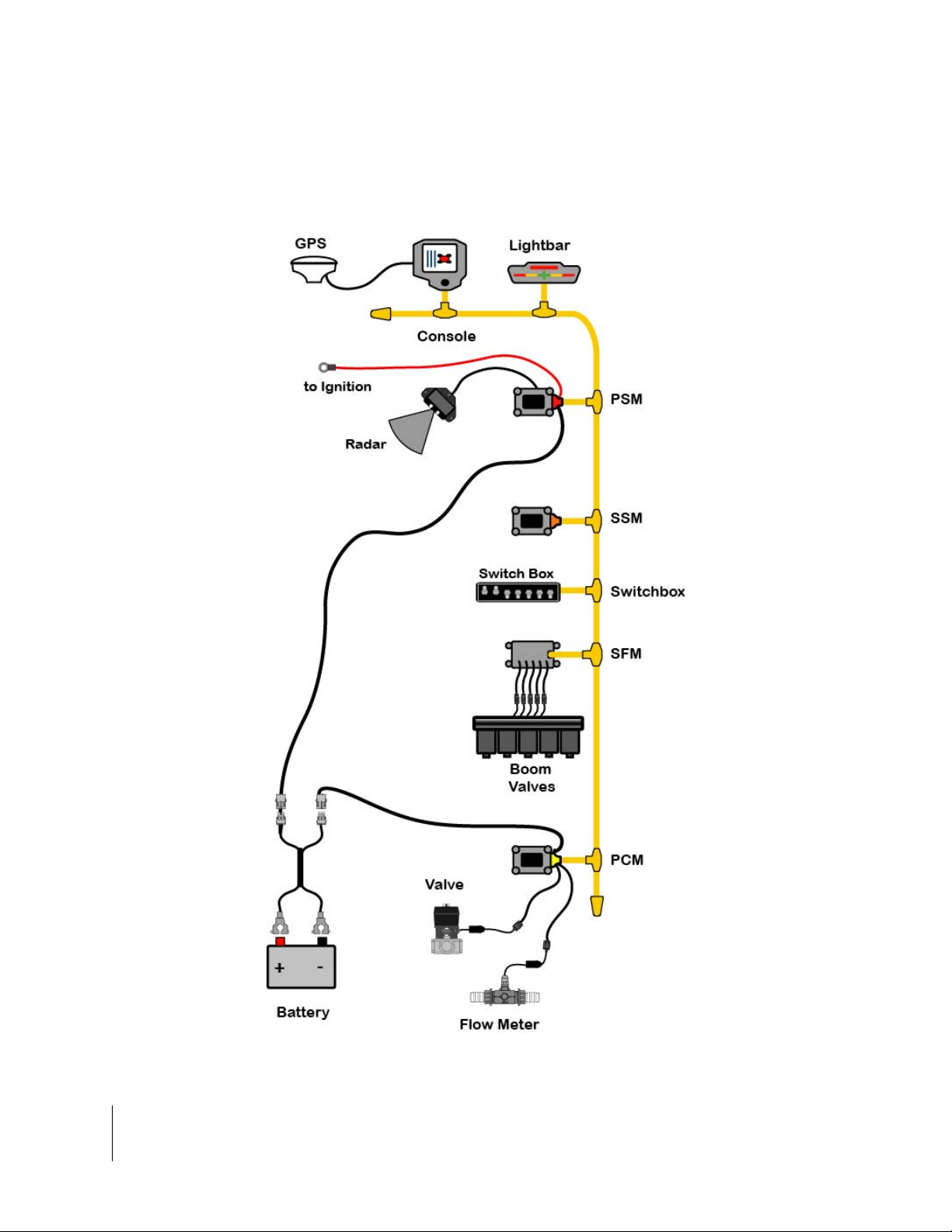
Single Channel Liquid with AutoBoom Shutoff (SFM)
This configuration show the Autoboom Shutoff feature using the Switch Function Module (SFM)
Figure 1-12: Single Channel Liquid with AutoBoom Shutoff
1-16 Chapter 1 - System Introduction
Typical Legacy 6000 Configurations
Page 27
Fieldware for The Legacy 6000
Software Version 2.11
Dual Channel with Wet and Dry Booms
This is a typical two product configuration, one liquid and one dry, for a vehicle with wet and dry
booms.
Figure 1-13: Dual Channel Wet/Dry Configuration
Chapter 1 - System Introduction 1-17
Typical Legacy 6000 Configurations
Page 28
Fieldware for The Legacy 6000
Software Version 2.11
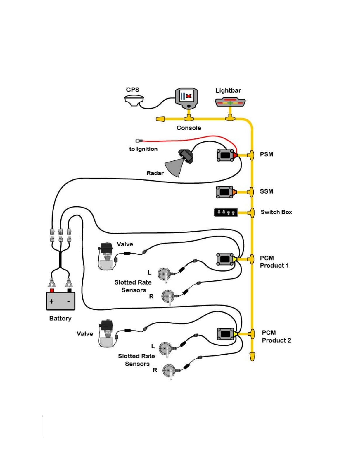
Dual Channel Granular with Two Sensors per Channel
This is a typical two product granular layout with two slotted rate sensors per channel.
Figure 1-14: Dual Channel Granular with Two Sensors per Channel
1-18 Chapter 1 - System Introduction
Typical Legacy 6000 Configurations
Page 29

Fieldware for The Legacy 6000
Software Version 2.11
Chapter Notes
Chapter 1 - System Introduction 1-19
Chapter Notes
Page 30

Fieldware for The Legacy 6000
Software Version 2.11
1-20 Chapter 1 - System Introduction
Chapter Notes
Page 31

Chapter 2 - Getting Started
Setting up "Fieldware for the Legacy 6000".
Software Version 2.11
Midwest Technologies IL, LLC
Fieldware for the Legacy 6000
Page 32

Fieldware for the Legacy 6000
Software Version 2.11
Software Overview
This section assumes that the Legacy 6000 hardware has been properly installed and clean reliable power has been supplied. For a list of typical hardware configurations (See “Typical Legacy
6000 Configurations” on page 1-14.).
Figure 2-1: The Legacy 6000 Console
Powering Up
To power up the Legacy 6000 console, press the orange button to the left side of the console faceplate (Figure 2-1). When the Legacy 6000 console has been powered up, "Fieldware for the Legacy 6000" will automatically start up. The first software page you will see is the Main Fieldware
Launcher (Figure 2-2). System Setup, System Tools, Application Rate Manager (ARM) and Mapper are easily accessible from the Main Launcher Page. This Chapter focuses on how "Fieldware
for the Legacy 6000" operates and how to configure your system using the System Setup application.
System Setup
System Tools
Figure 2-2: Main Launcher Page
Operate ARM
Mapper
2-2 Chapter 2 - Getting Started
Software Overview
Page 33

Fieldware for the Legacy 6000
Software Version 2.11
Screen Navigation & Selection
An operator can easily navigate around the screen by using the buttons o n the fa ce of th e Le gacy
6000, or with the connection of a USB keyboard. The buttons on the face of the Legacy consist of
four navigation arrows, escape (esp), enter, and ten function buttons(Figure 2-3). The ten function
buttons, five down the left and five down the right will be the fastest way to navigate and select
items on the screen. When using the USB keyboard the buttons on the keyboard have the same
function as those on the screen (Figure 2-4).
Figure 2-3: Legacy 6000 Screen Navigation & Selection Buttons
Figure 2-4: USB Keyboard Screen Navigation & Selection Buttons
Chapter 2 - Getting Started 2-3
Software Overview
Page 34

Fieldware for the Legacy 6000
Software Version 2.11
Standard Pages
Three basic types of software pages are used in "Fieldware for the Legacy 6000", a Launcher
page (Figure 2-5), a Setup Menu page (Figure 2-6), and a Data Entry page (Figure 2-7) and (Figure 2-8). Each is described in more detail below. Each of these page types has its own help window which displays pertinent information about a button or highlighted area of the page. Learning
how to use each of these page types allows the competent operation of the Fieldware software.
Launcher Page
A Launcher page typically contains sever al smaller applications (programs) that are run (l aunched)
from that Launcher page. For example, the Launcher page below, (Figure 2-5), is the System
Setup launcher from the Main Launcher Page. Several setup applications, such as the Console
and Product Control Module setup, can be accessed from here. In this Launcher page figure, the
highlighted software button is GPS Receiver setup and the associated help text is displayed in the
help window at the top of the page.
Software Version, page
name and number
Highlighted Button
Help Window
Figure 2-5: Example of a Launcher Page
2-4 Chapter 2 - Getting Started
Software Overview
Page 35
Fieldware for the Legacy 6000
Software Version 2.11
Setup Menu Page
A Setup Menu page (Figure 2-6) is a page that contains all of the setup parameters associated
with a particular setup theme, such as GPS Receiver. A Setup Menu page can be divided into
three columns, Left, Center and Right. The Left and Right columns are made up of software buttons adjacent to a physical key on the console. The center column is a scrollable list contain ing the
name of every setup parameter and its current value. Navigate to the center column using the up
and down arrow keys on the console (Figure 2-1). To edit any of these settings, highlight the
desired setting in the center column and press the enter key on the console. This action typically
selects a Data Entry page (Figure 2-7) and (Figure 2-8).
Setup Wizard
Typically the top item in the center column list is a setup wizard. This setup wizard sequentially
steps through each setup p a rameter Dat a Entr y pa ge, allowing the e diting of that settin g, and then
continuing on to the next setup parameter. This is a convenient method for new users, who are
unfamiliar with all of the setup parameters.
Setup Sub-Groups
In some Setup Menu pages there are sub-group buttons in the right and left columns. Pressing
one of these displays only the setup parameters associated with that sub-group, in the center column. For example, in GPS Receiver setup (Figure 2-6) there are three sub-group buttons. The
Globe button (right column) will display all setup parameters associated with GPS Receiver setup,
the next button down is the sub-group for receiver accuracy. Pressing this button reduces the
items in the center column to setup parameters associated with GPS accuracy, eliminating all of
the items associated with the other sub-groups.
Exiting a Setup Menu Page
There are two ways to exit a Setup Menu page: “Save and Exit” and “Exit with out saving
changes”. To exit the setup with out saving changes, press the back arrow button located at the
top of the left column. To exit and save any changes you made, press the forward arrow at the top
of the right column. Either of these methods returns you to the Launcher page th at the setup menu
was accessed from.
Back Arrow
Exit & No Save
Highlighted Setup
Parameter
Left Column
Center Column
Right Column
Forw ard A rrow
Save & Exit
Sub-group
buttons
Figure 2-6: Example of a Setup Menu Page
Chapter 2 - Getting Started 2-5
Software Overview
Page 36

Fieldware for the Legacy 6000
Software Version 2.11
Data Entry Page
Data Entry page may be an alpha-numeric entry or a pick list (Figure 2-7). The Data Entry page is
also divided into three columns: Left, Center, and Right. The left and right columns contain software buttons, typically only the back and forward arrow buttons. The center column is the data
entry dialog box. Use the arrow keys on the console to navigate around the Data Entry page. The
bottom half of the Data Entry page is comprised of a text window with a white background. This
window can contain a description of the current setting as well as some help text.
Pick List Data Entry
To select a setup parameter setting in a Data Entry page that employs a pick list in the dialog box,
highlight the dialog box (center column) using the left or right arrow key. Using the up and down
arrow keys spin though the available setting selections. When the desired setting is in view in the
dialog box press enter to save the setting or press the forward arrow.
Back Arrow
Exit & No Save
Setting description
and help text window.
Forw ard A rrow
Save & Exit
Name of Setup
Parameter
Figure 2-7: Example of Pick List Data Entry Page
Alpha/Numeric Data Entry
To enter a value in a Data Entry page that emp loys an alpha/nu meric dia log bo x (Figur e 2-8), h ighlight the desired character and use the up or down arrow key to spin through the alpha/numeric
character list. When the desired character is in view in the dialog box press the right arrow key to
move to the next character space in the dialog box. When the desired setting is in view in the dialog box press enter to save the setting or press the forward arrow.
If you are entering a numeric value, you can use the decimal point in the character set to set the
number of digits to the left and right of the decimal point, (E.G. 0.254, 1.00, 10.0, 100.463).
Left most character space
in the data entry dialog box.
Figure 2-8: Example of Alpha/Numeric Data Entry
2-6 Chapter 2 - Getting Started
Software Overview
Page 37

Fieldware for the Legacy 6000
Software Version 2.11
System Setup
The Fieldware System Setup allows the configuring of the Legacy 6000 to best suit job needs. To
access the System Setup launcher press the top left button in the Main Launcher page see the left
image in (Figure 2-9), the help text should say Configure System Settings. This brings up the System Setup Launcher page right image (Figure 2-9). The table below lists the current system components that can be configured. Each component is covered in more detail in sections below.
Figure 2-9: System Setup Page
Setup Description
Console Defines system environment variables such as units, language, date, and time.
Lightbar Defines Swath lightbar settings and lightbar messages.
GPS Receiver Allows you to configure your GPS receiver from the Legacy 6000 console.
PCM Configures each Product Control Module that is connected to the Legacy 6000 system.
Implement Defines the vehicle’s implement, including implement width, number of swaths and sections.
Table 2-1: Current System Setup Components
Chapter 2 - Getting Started 2-7
System Setup
Page 38

Fieldware for the Legacy 6000
Software Version 2.11
Console Setup
Console Setup defines system environment settings (units, language, time) that are displayed on
the console and used in the rate control and guidance applications.
To change any of the system en vir on m en t set tin gs, high ligh t th e set tin g na m e, listed in the cent er
column of the Setup page, and press enter. Use the Setup Wizard to walk through all setup options
and select the appropriate settings. When don e ma king cha ng es, pre ss the for ward arro w to sa ve
and exit Setup. Press the back arrow to exit and not save any changes. This procedure will hold
true for Console, Lightbar and GPS Receiver Setup.
.
Figure 2-10: The Console Setup Menu Page
Setting Description
PC Card Indicates to the Legacy 6000 system that a PCMCIA data card is being used.
Units Defines the system units: Metric or US.
Language Defines the system language.
System Date Sets the system date.
Date Format Defines the date format that will be displayed on the console. Settings are MM/DD/YY or DD/MM/
YY.
System Time Sets the system time.
Time Format Defines the time format to be displayed on the console. Settings are 12 hr. and 24 hr.
Time Zone Sets the time zone the Legacy 6000 system is operating in.
Speaker Sets the system speaker option: internal or external.
Volume Sets the speaker volume.
Table 2-2: Console Setup Settings
2-8 Chapter 2 - Getting Started
Console Setup
Page 39

Fieldware for the Legacy 6000
Software Version 2.11
Lightbar Setup
Lightbar setup defines how the Legacy 6000 console configures the lightbar. Lightbar setup
parameters are listed in Table 2-3.
Figure 2-11: The Lightbar Setup Menu Page
Setting Description
Lightbar Defines which lightbar features are used. Settings are Text/Lights, Text Only, or Off.
LED Brightness Sets the brightness level of the lightbar LEDs and text window.
Display Mode Defines how the user interprets the row of LEDs on the lightbar. The center stack of Green
LEDs can represent the current guideline (Swath Mode) or the vehicle (Vehicle Mode).
Drive sensitivity Sets the distance that a single LED in the row of LEDs represents (Typically 1.5 feet).
Look Ahead The number of seconds ahead of the vehicle that the cross track error is calculated at (Typi-
Alarm Defines the situation in which the alarm sounds. Settings are Off, Alarm, Hazards, and All.
Hazard Range Sets the distance prior to an impending feature (Hazard or Applied Area).
Parallel MSG 1
Parallel MSG 2
Parallel MSG 3
Curved MSG Defines which of several lightbar messages are displayed in the #1 Curved MSG location.
cally 2.0 seconds).
Defines which of several lightbar messages are displayed in the #1, #2, #3 MSG location.
Choices are X-Track, Swath #, Heading Error, Ground Speed, Area Applied, Off, Application
Rate, and X-Track/Swath#. Once a choice has been selected it will not appear as a option for
the next two messages.
Only the Curved MSG is used when in Headlands guidance mode. Choices are Area Applied,
Ground Speed, X-Track, Application Rate, and Off.
Table 2-3: The Lightbar Setup Settings
Chapter 2 - Getting Started 2-9
Lightbar Setup
Page 40

Fieldware for the Legacy 6000
Software Version 2.11
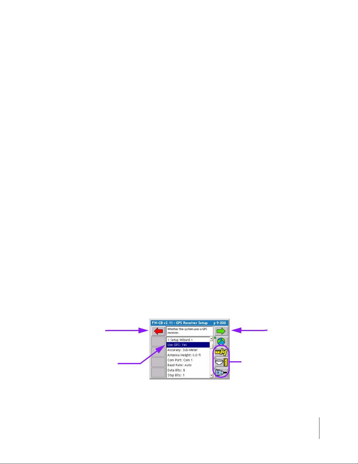
GPS Receiver Setup
GPS Receiver setup defines your DGPS accuracy and how the GPS receiver communicates with
the Legacy 6000 console. GPS Receiver setup parameters are listed in Table 2-4.
Figure 2-12: The GPS Receiver Setup Menu Page
Setting Description
Use GPS Defines whether the Legacy 6000 system is using GPS. If using GPS this setting must be set to
Yes.
Accuracy Defines the accuracy of the DGPS receiver. Choices are RTK and Sub-meter.
Com Port Defines the com port that your GPS receiver is connected to.
Baud Rate Defines the selected com port baud rate.
Data Bits Defines the selected com port data bit setting.
Stop Bits Defines the selected com port stop bit setting.
Parity Defines the selected com port parity.
Table 2-4: The GPS Receiver Setup Settings
2-10 Chapter 2 - Getting Started
GPS Receiver Setup
Page 41

Fieldware for the Legacy 6000
Software Version 2.11
Implement Setup
Implement Setup is where the number of Swaths, number of Sections per Swath, and the physical
relationship (distance and direction) of a Swath to the position of the GPS antenna are defined.
Implement Setup is a step by step (Wizard fashion) process.
This is a single
swath made up of
three sections.
Figure 2-13: The Vehicle-Swath-GPS Antenna Relationship
The Vehicle Coordinate System
In order to properly capture the relationship between swaths and the GPS antenna on the veh icle,
"Fieldware for the Legacy 6000" has defined a coordinate system based around the center line of
the vehicle (Figure 2-13). Review this Ve hicle Coordinate System prior to running Implement
Setup. It is also a good idea to make all of measurements, such as dist ance fro m GPS Antenna to
Swath, prior to running Implement Setup.
The X and Y Axes
In "Fieldware for the Legacy 6000", a vehicle has two axes: an X and a Y. The X axis runs perpendicular to the center line of the vehicle and the Y axis is the center line of the vehicle (Figur e 2-13).
Directions along the X axis are referred to as right and left, while directions along the Y axis are
referred to as forward and back.
Location of GPS Antenna
The GPS Antenna must be mounted along the center line, the Y-Axis, of the vehicle (Figure 2-13).
Swaths and Sections
In version 2.11 of "Fieldware for the Legacy 6000" a vehicle can have as many as four swaths and
up to 20 sections total across all swaths. A vehicle with a single swath divided into three sections
is shown in Figure 2-13.
Chapter 2 - Getting Started 2-11
Implement Setup
Page 42

Fieldware for the Legacy 6000
Software Version 2.11
Entering the Implement Width
The first page in the Implement Setup process is the implement width (Figure 2-14). This width is
used for guidance purposes and is considered the distance between guidelines. This width is typically determined by the vehicle swath or spread wid th. Setting the Implement wid th slightly smaller
than the actual width reduces skips. Setting the Implement width slightly larger than the actual
swath width reduces overlap. Setting the implement width to a width other than the actual width
reduces the accuracy of the area applied.
Figure 2-14: The Implement Width Page
The Implement Width page contains a Review Configuration button. Pressing this button brings up
a page that details the current Implement configuratio n No settings can be changed from this p age
(Figure 2-15).
Review Configuration
Button
Figure 2-15: Review of Implement Configuration
2-12 Chapter 2 - Getting Started
Implement Setup
Page 43

Fieldware for the Legacy 6000
Software Version 2.11
Number of Swaths Page
Currently the maximum number of swaths that "Fieldware for the Lega cy 6000" can ha ndle is four.
The Majority of applications will have One swath. For more on multiple swath applications and
examples see
Figure 2-16: The Number of Swaths Page
Entering the Number of Sections in a Swath
The Sections page is where the number of sections in a swath are entered. The maximum number
of sections is 20 (not 20 sections per swath, 20 sections for the entire system).
Swath sections are ordered left to right with respect to a forward facing vehicle. The left most section
is assigned number 1 and section numbers increase moving to the right (Figure 2-17).
Figure 2-17: The Number of Sections in Swath 1 Page
Chapter 2 - Getting Started 2-13
Implement Setup
Page 44
Fieldware for the Legacy 6000
Software Version 2.11
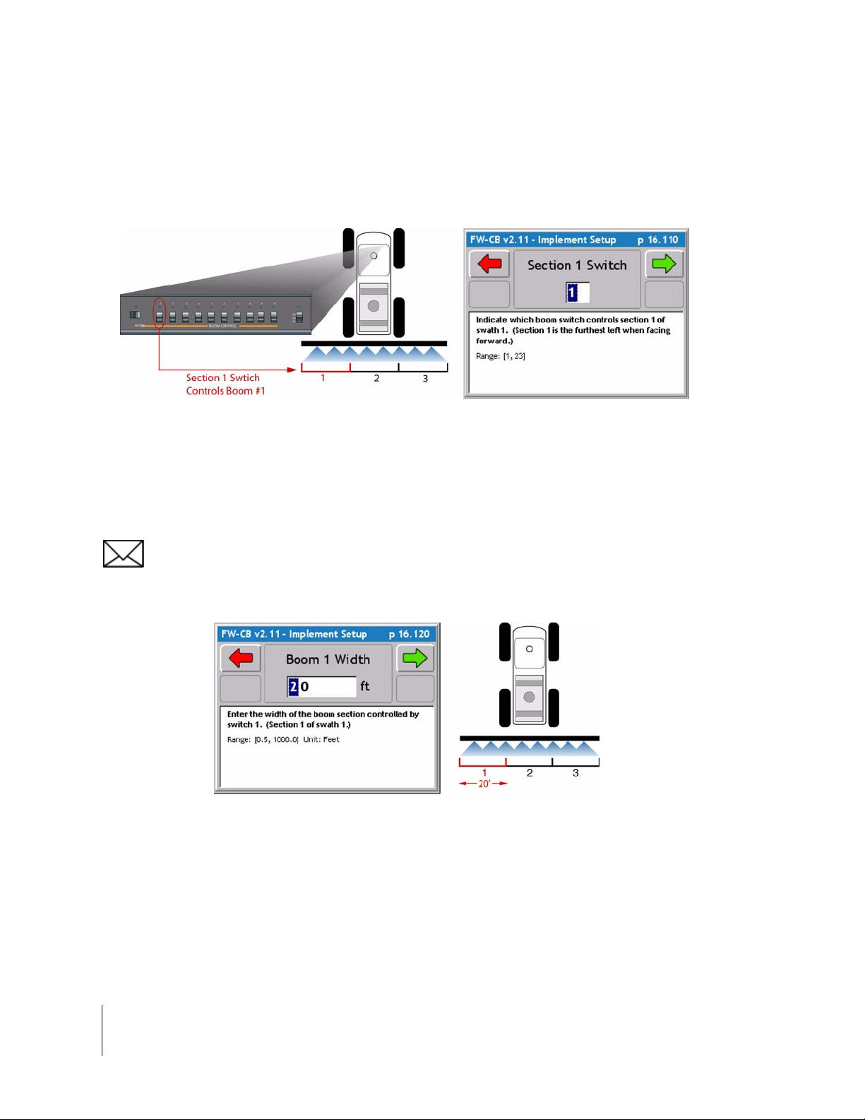
Setting the Section to Switch Assignment
The Section to Switch page allows you to assign a physical boom switch to the curr ent Swath Se ction. This allows the control of individual sections.
Figure 2-18: The Section to Switch Assignment Page
Entering the Section Width
The Section Width page is where the width of a sectio n is entered. Whe n the correct section wid th
is entered, press the forward arrow button to move to the next setup page.
If there is more than one section for a swath, Implement setup wil l alte rnate between Section to
Switch Assignment and Section Width until all sections have been completed.
Figure 2-19: The Section Width Page
2-14 Chapter 2 - Getting Started
Implement Setup
Page 45

Fieldware for the Legacy 6000
Software Version 2.11
Entering the Offset Direction Y
The Y direction offset is the direction, (along the center line of the vehicle) from the GPS antenna
to the center of a swath (Figure 2-20).
Figure 2-20: The Offset Direction Y Page
The Offset Distance Y
When the Y Offset Direction has been entered, enter the Y Offset Distance. This is the distance
from the GPS antenna along the vehicle center line to the swath.
Figure 2-21: The Offset Distance Y Page
Chapter 2 - Getting Started 2-15
Implement Setup
Page 46

Fieldware for the Legacy 6000
Software Version 2.11
Entering the Offset Direction X
The Offset Direction X (Figure 2-22) is the direction perpendicular (left or right) of the vehicle center line that the center of a swath is offset. T ypically this will be set to Centered, as most swaths are
centered on the vehicle’s center line.
If an Offset Direction X of either Right or Left is selected, the next setup page (Figure 2-23) will ask
for the distance of this offset. If Centered is selected, there is no distance and ther efor e an inp ut a
distance is not asked for.
Figure 2-22: The Offset Direction X Page
Figure 2-23: The Offset Distance X Page
2-16 Chapter 2 - Getting Started
Implement Setup
Page 47

Fieldware for the Legacy 6000
Software Version 2.11
Setting the PCM Assignment
The PCM Assignment page allows the assigning of a Product Control Module (PCM) to a swath or
swaths. The PCM must be setup prior to assigning it to a swath. A swath can have a single PCM
assigned to it or all PCMs assigned to it.
When a PCM has been assigned to a Swath, press the forward arrow button to move to the next
setup page.
This completes the single swath setup. Implement Setup will loop through several of the previous
setup pages based on the number of swaths entered and number of sections for each swath.
Figure 2-24: The PCM Assignment Page
Chapter 2 - Getting Started 2-17
Implement Setup
Page 48

Fieldware for the Legacy 6000
Software Version 2.11
Completing Implement Setup
When all swaths and sections have been properly setup, the last Implement Setup page is the Finish page. There are two buttons on the Finish page: a Review Configuration button and a Save to
SSM (Switch Sense Module) button.
Pressing the Review configuration button will display all of the implement setup settings that have
just been entered (Figure 2-15).
The Save to Switch Sense Module (SSM) button will send the current Implement configuration
parameters to the Switch Sense Module.
Save to SSM Button
Review Button
Figure 2-25: The Implement Setup Finish Page
2-18 Chapter 2 - Getting Started
Implement Setup
Page 49

Fieldware for the Legacy 6000
Software Version 2.11
Product Control Module (PCM) Setup
The Product Control Module (PCM) setup is used to configure a PCM that is connected to the MidTech Legacy 6000 CAN Bus. A PCM can not be configured if it is not connected to the Mid-Tech
CAN Bus.
Setting up a PCM is typically required in the following scenarios: The initial Legacy 6000 hardware
installation, when an additional PCM is added to the system, or to modify an existing, already configured, PCM. PCM setup consists of ten Main Setup Headers, (Favorites, Application, Drive Type,
Units, Primary Sensor, Secondary Sensor, Monitors 1, Monitors 2, Monitors 3, and Monitors 4)
Table 2-5, each Header has detailed setup parameters to fit the operators application.Information
entered in a PCM setup Main Setup Headers may effect subsequent PCM settings and pages.
Review the setup procedure before running PCM setup. If in doubt, contact your Mid-Tech customer service representative.
To access PCM Setup, select System Setup from the main Launcher page. This brings up the System Setup page. From the System Setup page, select PCM Setup. This brings up the PCM Setup
page. The PCM Setup page will have a button for each PCM the software detects on the CAN bus.
If there is only one PCM connected this page will not appear and will advance directly to the First
Main Setup Header (Favorite). Each button will display the PCM number, Serial Number and PCM
Name(Figure 2-26). Select the desired PCM to be setup and press enter.
PCM Number
PCM Name
PCM Serial Number
Figure 2-26: The PCM Setup Launcher Page
Chapter 2 - Getting Started 2-19
Product Control Module (PCM) Setup
Page 50

Fieldware for the Legacy 6000
Software Version 2.11
Page
Name
Description
Allows a setup configuration to be selected or saved.
Defines the type of product application or device being controlled, such as Liquid or Granular.
Select the drive circuit used to control the product delivery or device.
Select the units used for the application rates.
Defines the type of sensor used for the primary control function.
Defines the type of sensor used for the secondary control function.
Defines the type of sensor used as a monitor. There are four monitor pages. This sensor is not
used for product control.
Allows the PCM configuration to be saved as a favorite and updates the PCM with the new config-
uration.
Table 2-5: PCM Setup - Main Setup Head ers
2-20 Chapter 2 - Getting Started
Product Control Module (PCM) Setup
Page 51
Fieldware for the Legacy 6000
Software Version 2.11
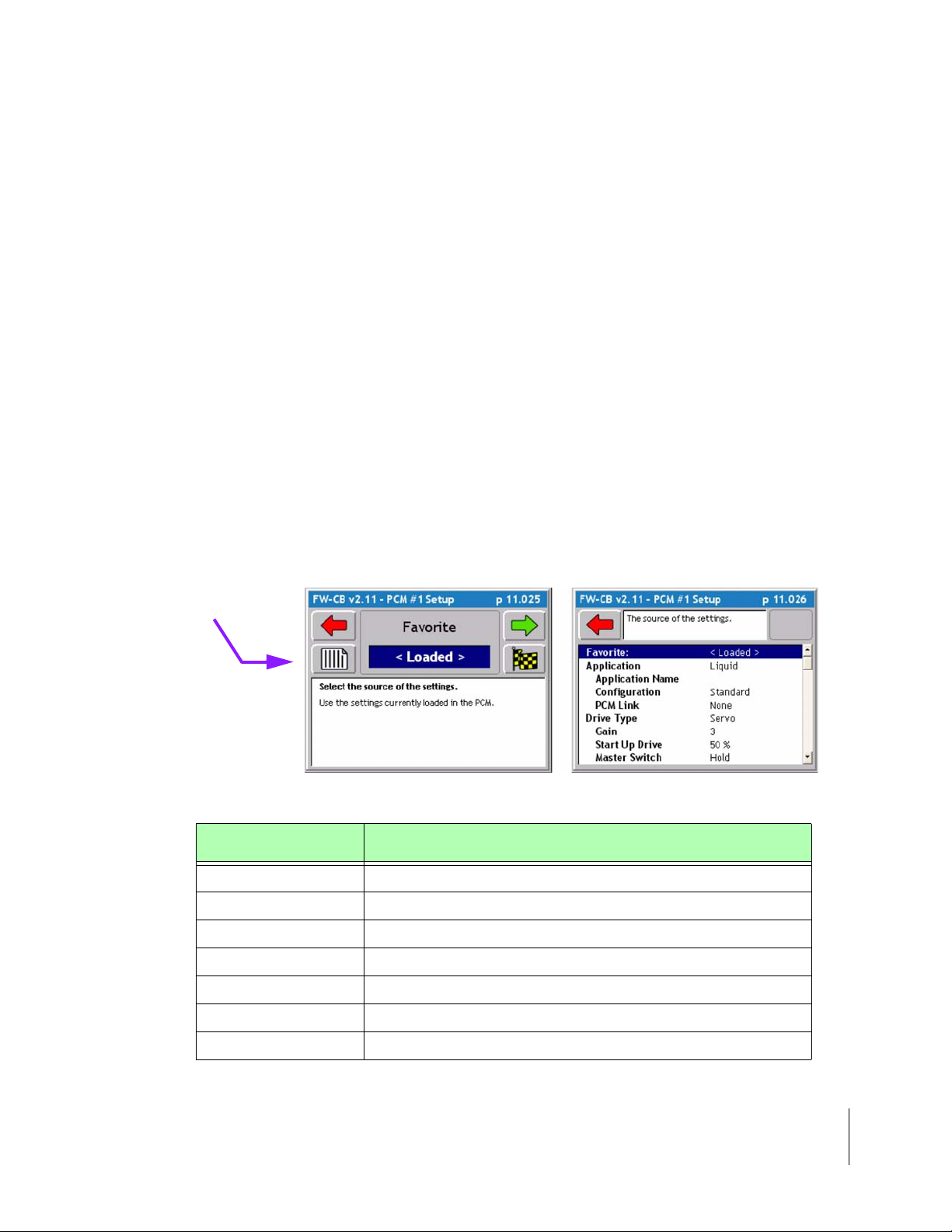
Selecting a PCM Setup Favorite
The first setup page is the PCM Favorite (Figure 2-27). When the operator configures all PCM
Setup parameters the settings can be saved as a Favorite. Favorites are completed saved versions of PCM setup. Mid-Tech has taken the time to provide some very basic PCM setups for liquid
and dry applicationsTable 2-6.To view all the default settings for the pre-created favorites (See
“Appendix A - PCM Favorites Settings” on page A-1.) One of the favorites may come close to fitting your application, it will be very helpful to use the closest pre-created favorite to your application as a starting point and adjust as nee ded. When PCM setup is complete save the setup as your
own personnel Favorite. This is very useful if the Legacy is used in more tha n one application. This
feature will prevent the operator from setting up the PCM every time the application changes, just
select the favorite created for the application and press the Finish flag, apply the settings and GO!
The default configuration is always the current configuration and is listed as <Loaded> in the dialog pick list. When creating a new configuration, name the configuration, at the end of the setup
process, on the Finish page.
To view the settings of the loaded configuration, press the review button (Figure 2-27).
Select the desired favorite that best matches the application and press the Forward arrow to
advance to the next PCM Setup page (Figure 2-28). If no other changes are required, press the
Finish button and go directly to the last setup page “Finishing the PCM Setup” on page 2-38.
Review Settings
Button
Figure 2-27: The PCM Setup Favorites Page
Favorites Description
GRANC-A Defines a granular application in Split-Drive with three monitors.
GRANPWM-A Defines a granular application using a PWM valve.
GRANSERVO-A Defines a granular application using a Servo valve with one Monitor (shaft).
GRANSERVO-B Defines a granular application using a Servo valve with No monitor.
INJ-A Defines an injection application.
LIQFLOW-A Defines a liquid application using a flowmeter with one monitor.
SPINMOTOR-A Defines a Shaft sensor used to control spinner speed.
Table 2-6: PCM Pre-Created Favorites
Chapter 2 - Getting Started 2-21
Product Control Module (PCM) Setup
Page 52

Fieldware for the Legacy 6000
Software Version 2.11
Setting the Application Type
The Application Setup page (Figure 2-28) allows the selection of the required type of product application. All other setup pages will be based on the type of application chosen on this page. There
are five possible applications: Liquid, Granular, Seeder, NH3, and Motor.
For each Application type there is an additional Settings pag e. To access the Settings page, press
the Settings button on the Application page (Figure 2-28). Typically it will not be necessary to
change any parameters found in the Settings page.
Select the Application type and press the Forward arrow to advance to the next PCM Setup page.
When changing the application type, the Finish Flag button may disappear. This button disappears
if the change in application type caused additional changes to other PCM setup parameters. It may
be necessary to continue viewing the remaining setup parameters prior to finishing the PCM setup
process. If no additional PCM parameter changes occurred, the Finish button is presented and a press of this
button brings up the last setup page. From the Finish page, update the PCM with the new setup file.
Settings Button
Figure 2-28: The Application Page
2-22 Chapter 2 - Getting Started
Product Control Module (PCM) Setup
Application Type Options
Page 53

Fieldware for the Legacy 6000
Software Version 2.11
Application Type Settings
All Application Types have the same setting options when the settings button is pressed, review
(Table 2-7) for a detailed description of the settings.When the Application Type settings and
parameters are selected, press the Forward arrow to advance to the next PCM Setup page
Application
Settings
Application Name A user defined name used to label a particular application (PCM). Users typi-
cally label this the same as the PCM favorite name.
Configuration Defines the relationship between the sensor and the product.
Standard Liquid - All material that is recorded by the rate sensor is discharged through the boom.
Standard Granular - Material shaft speed should change as booms are
turned off.
Split - Only used in a granular application. Material shaft speed does not
change as booms are turned off.
Reflow - Only used in a liquid application. Material from a closed boom valve
is recirculated back to the tank or pump.
PCM Link If more than one PCM is in use the PCM can be linked to one another. This is
used if one product is dependent on the other product for proper application.
When PCM’s are linked and one would fail, both PCM’s would shut down.
Description
Table 2-7: Application Type Detailed Settings
Chapter 2 - Getting Started 2-23
Product Control Module (PCM) Setup
Page 54

Fieldware for the Legacy 6000
Software Version 2.11
Setting the Drive Type
The next PCM Setup parameter is Drive Type. This is the type of drive circuit used to control the
delivery of a product. The list of available drive types depends on the Application selected in the
previous setup page. Some Drive Types have an additional Drive Types Settings page, (See
“Drive Type Settings” on page 2-26.), accessed from the Settings button on the Drive Type page.
Figure 2-29: The Drive Type Page
Drive Type Description
Servo Application rate is controlled by a bi-directional motorized valve.
PWM Application rate is controlled by a pulse-width modulated hydraulic valve.
DC Motor Application rate is controlled by varying the speed of a DC motor. (Does not
include injection)
Injection Application rate is controlled by varying the speed of a direct injection pump.
Table 2-8: Drive Type Options
2-24 Chapter 2 - Getting Started
Product Control Module (PCM) Setup
Page 55

Fieldware for the Legacy 6000
Software Version 2.11
Drive Type Settings
Three of the Drive Types have setting options, Servo, Injection and PWM. Review (Table 2-9) for
detailed Servo settings, (Table 2-10) for detailed PWM settings, and (Figure 2-11) for detailed
Injection settings. When the Drive Type settings and parameters are selected, press the Forward
arrow to advance to the next PCM Setup page
Servo Settings Description
Gain Defines the speed at which the PCM reacts to an off target condition.
Decrease to postpone reaction and Increase to speed up reaction. (Gain setting too high can result in oscillation)
Start Up Drive Defines the level used to open valve from full closed position. Increase if valve
open too slowly and decrease if valve opens too quickly.
Master Switch Control valve response to all booms off.
Implement Status Defines control valve response when implement status is open (Off)
Valve Delay Enter delay in resuming control after turning all booms on. When the control
Valve Location Defines the location of the control valve in the plumbing (In-Line or Bypass).
Hold - Control valve will hold in the same position
Closed - control valve will drive full close
Hold - Control valve will hold in same position
Closed - Control valve will drive full closed
valve is set to close this feature is activated when resuming control and the
rate exceeds the target rate the valve will delay control for the set value.
Also used with combination in-line / bypass valve like the Autorange and most
hydraulic servos.
Table 2-9: Drive Type -Servo Detailed Settings
PWM Settings Description
Gain Defines the speed at which the PCM reacts to an off target condition.
Decrease to postpone reaction and Increase to speed up reaction. (Gain setting too high can result in oscillation)
Frequency Defines the frequency of the drive signal specified by the manufacturer.
Table 2-10: Drive Type - PWM Detailed Settings
Chapter 2 - Getting Started 2-25
Product Control Module (PCM) Setup
Page 56

Fieldware for the Legacy 6000
Software Version 2.11
PWM Settings Description
Minimum Duty Cycle Defines the min. duty cycle the valve will respond to, specified by the manufac-
turer.
Maximum Duty Cycle Defines the max. duty cycle the valve will respond to, specified by the manu-
Ramp Time Defines the time it takes the valve to go from min. duty cycle to max. duty
Dither Prevents valve from sticking. This value is specified by the manufacturer.
Master Switch Control valve response to all booms off.
Implement Status Defines control valve response when implement status is open (Off)
Valve Delay Enter delay in resuming control after turning all booms on. When the control
facturer.
cycle. Decrease if the valve reacts too slowly when off target. Increase if control reacts too quickly (overshooting target rate).
Hold - Control valve will hold in the same position
Closed - Control valve will drive full close
Resume - Control valve will close when booms are turned off, but will resume
at the last duty cycle setting when booms are turned on again.
Hold - Control valve will hold in same position
Closed - Control valve will drive full closed
Resume - Control valve will close when booms are turned off, but will resume
at the last duty cycle setting when booms are turned on again.
valve is set to close this feature is activated when resuming control and the
rate exceeds the target rate the valve will delay control for the set value.
Table 2-10: Drive Type - PWM Detailed Settings
Injection Settings Description
Prime Volume Define the amount of liquid needed to prime the pump. This is the volume
Table 2-11: Drive Type - Injection Detailed Settings
Calculating the Prime Value
(Line diameter/2) X 3.1416 X Line length X 0.5541 = Volume in Fluid Ounces
2-26 Chapter 2 - Getting Started
Product Control Module (PCM) Setup
needed to fill plumbing lines from chemical tanks to the injection point, use the
formula below to calculate the Prime Value. The Prime feature is located on
the ARM launcher page (See “Prime Injection System” on page 3-25.)
Page 57

Fieldware for the Legacy 6000
Software Version 2.11
Setting the Units
When the Drive Type is selected, the next PCM Setup page is the Units page (Figure 2-30). The
available units are based on the Application and Drive Type selected. There is an additional page
associated with the Units page. This is the Con trol Basis page (Figure 2-30 ) ri gh t image. The Control Basis page determines whether the units available to you are Area based, Time based, or Distance based. Set this parameter prior to selecting the application units. When the Control Basis
and Units parameters are selected, press the Forward arrow to advance to the next PCM Setup
page
Control Basis
Button
Figure 2-30: The PCM Setup Units Page
Application Types Description
Liquid
Granular
Seeder Area - lb/ac - sd/ac - tubers(tb)/ac - kg/ac
NH3 Area - lb/ac - kg/ac
Motor Time - rpm
Injection
Area -gal/ac - gal/1000ft
Distance - gal/lmi
Time - gal/min
Area - lb/ac - lb/1000ft
Distance - lb/mi - lb/lmi - tn/lmi - tn/mi
Time - lb/min - tn/h -
Area - fl oz/ac - fl oz/1000ft
Distance - fl oz/lmi
Time - fl oz/ min
2
- gal/100yd2 - l/ac
2
- lb/100yd2 - tn/ac - kg/ac
2
- fl oz/100yd2 - l/ac
Table 2-12: Application Type Options
Chapter 2 - Getting Started 2-27
Product Control Module (PCM) Setup
Page 58

Fieldware for the Legacy 6000
Software Version 2.11
Selecting the Primary Sensor
The Primary Sensor is the type of sensor used for the primary control function. The Primary Sensor types available in this pick list are based on the Application type selected. Each Primary sensor type has an associated Settings button (Figure 2-31) which goes to the Sensor Settings page
(Figure 2-32). The Sensor parameters depend on the type of Primary Sensor selected.
Each PCM has six input sensors labeled A through F. Sensor inputs A - D are digital and sensor
inputs E and F are analog. Your PCM CAN Bus cable harness comes with the sensor input lines
labeled A - F. You can set the input line for a sensor in the Sensor Settings page.
Figure 2-31: The Primary Sensor Page
Application Type Primary Sensor Options
Liquid Flowmeter, Pressure Digital, and Pressure Analog
Granular Granular
Seeder/Motor Shaft
NH3 Flowmeter
Injection Injection
Table 2-13: Primary Sensor Options
2-28 Chapter 2 - Getting Started
Product Control Module (PCM) Setup
Page 59

Fieldware for the Legacy 6000
Software Version 2.11
Primary Sensor Settings
Primary Sensors Flowmeter, Granular, Injection and Shaft have detailed settings that are the
same. Review (Table 2-7) for a detailed description of the settings. The two other Primary Sensor s,
Pressure Digital and Pressure Analog, have the initial settings as well as an sub settings. To
access the sub settings locate the two Settings Buttons on the right side of the screen, use the two
buttons to swap between settings.(Figure 2-32). Review (Table 2-14) for a detailed Description of
the initial settings and (Table 2-15) for a detailed description of the sub settings for Pressure Digital
and Pressure Analog senors.When the Primary Sensor settings and parameters are selected,
press the Forward arrow to advance to the next PCM Setup page
Sensor Settings Definition
Input Defines digital and analog sensors. Senor inputs A-D are digital (flowemeter,
and slot sensors) and Senors E-F are analog (pressure).
Sensor Name A user defined name used to label a particular sensor or monitor. This informa-
Calibration Number Enter calibration number in units specified, this number is normally found on
Cal# Basis Table of preset calibration numbers. This can be used to rapidly change a cali-
Nozzle Constant Only use for Pressure application. Enter the gal/min rating of your nozzle at
tion is not stored in the PCM and is used for messaging to the user only.
the sensor. Physical calibration will further fine-tune this number. For NH3
applications (See “Appendix C - NH3 Application” on page C-1.)
bration number. See Appendix B for Cal# Basis setup.
10mph at 30psi
Table 2-14: Primary Sensor Settings
Chapter 2 - Getting Started 2-29
Product Control Module (PCM) Setup
Page 60

Fieldware for the Legacy 6000
Software Version 2.11
Figure 2-32: Pressure Digital & Analog Sub Settings Pages
Sensor Settings Definition
Alarm Units Pounds Force / Square Inch (PSI)
Min Alarm Defines the limit below which the min. alarm will be active.
Max Alarm Defines the limit above which the max. alarm will be active.
Alarm Delay Defines the duration the alarm condition must exist before triggering tan alarm.
Sensor Output Define the output signal type of the sensor. Contact the machine supplier for
this information.
Table 2-15: Primary Sensors - Pressure Digital & Analog Sub Settings
2-30 Chapter 2 - Getting Started
Product Control Module (PCM) Setup
Page 61

Fieldware for the Legacy 6000
Software Version 2.11
Selecting the Secondary Sensor
The Secondary sensor is used in conjunction with a Primary sensor . The Secondary Sensor types,
available in this pick list, are based on the Application type and Primary Sensor type selected (Figure 2-33). Each Secondary sensor type has a Settings Bu tton which brings u p the Sensor Settings
page. The Secondary Sensor parameters depend on the type of Primary Sensor selected (Table 2-
16).
Each PCM has six input sensors labeled A through F. Sensor inputs A - D are digital and sensor
inputs E and F are analog. The PCM CAN Bus cable harness comes with the sensor input lines
labeled A - F. The input line for a sensor can be set on the Sensor Settings page.
Figure 2-33: The Secondary Sensor Page
Primary Sensor Secondary Sensor Option
Flowmeter None
Pressure Digital Pressure Digital
Pressure Analog Pressure Analog
Granular Granular
Shaft Shaft
Injection None
Table 2-16: Secondary Sensor Options
Chapter 2 - Getting Started 2-31
Product Control Module (PCM) Setup
Page 62

Fieldware for the Legacy 6000
Software Version 2.11
Secondary Sensor Settings
Secondary Sensors Granular , Shaf t, Pressure Digi tal, and Pre ssure Analog have detailed setting s
that are the same. Review (Table 2-17) for a detailed description of the settings that are the sam e.
The two Pressure Sensors, Pressure Digital and Pressure Analog, have the initial settings as well
as an sub settings. Accessing the sub settings locate the two Settings Buttons on the right side of
the screen, use the two buttons to swap between settings.see (Figure 2-32) above. Review (Table
2-18) for a detailed description of the sub settings for Pressure Digital and Pressure Analog Secondary Senors. When the Secondary Sensor settings and para meter s ar e selecte d, pr ess the Fo rward arrow to advance to the next PCM Setup page
Sensor Settings Definition
Input Defines digital and analog sensors. Senor inputs A-D are digital (flowemeter,
Sensor Name A user defined name used to label a particular sensor or monitor. This informa-
Dual Warning% Defines the maximum acceptable % difference between the primary and sec-
Dual Warning Delay Defines the time that the primary and secondary senors outputs can exceed
and slot sensors) and Senors E-F are analog (pressure).
tion is not stored in the PCM and is used for messaging to the user only.
ondary sensor outputs before the operator is warned.
the dual warning % before initiating the alarm.
Table 2-17: Secondary Sensor - Settings
2-32 Chapter 2 - Getting Started
Product Control Module (PCM) Setup
Page 63

Fieldware for the Legacy 6000
Software Version 2.11
Sensor Settings Definition
Alarm Units Pounds Force / Square Inch (PSI)
Table 2-18: Secondary Sensor - Sub Settings
Chapter 2 - Getting Started 2-33
Product Control Module (PCM) Setup
Page 64

Fieldware for the Legacy 6000
Software Version 2.11
Selecting a Monitor
A Monitor is a sensor that is not a Primary or Secondary sensor and is used to monitor the status
of some element of the application delivery system, such as RPMs on a shaft sensor. Up to four
monitor sensors can be used in the delivery system. The Monitor types available in this pick list
(Figure 2-34) are based on the Application, Primary sensor, and Secondary sensor types selected.
Each Monitor type will have an associated Settings button which brings up the Monitor Settings
page right image in (Figure 2-34). The Monitor sensor parameters depend on the type of Monitor
sensor selected. Review (Table 2-19) for a list and description of the Monitor options.
PCM setup contains four Monitor setup pages; Monitor 1 thru Monitor 4. It is not necessary to
setup four monitors. Select the monitor(s) used and press the forward arrow to save the settings. If
there is no monitor, select the None setting and continue to the next page.
Each PCM has six input sensors labeled A through F. Sensor inputs A - D are digital and sensor
inputs E and F are analog. The input line for a sensor can be set on the Sensor Settings page.
Monitors Description
Shaft Monitor a shaft rotation speed.
Product Detect Monitor that product is discharging.
Low Bin Monitor low product level left to apply.
Status Monitor engaged or disengaged status.
Pressure Digital Monitor pressure related or not related to application.
Pressure Analog Monitor pressure related or not related to application.
Flowmeter Monitor flow of liquid using a flowmeter.
2-34 Chapter 2 - Getting Started
Product Control Module (PCM) Setup
Figure 2-34: The Monitor Page
Table 2-19: Monitor Options
Page 65

Fieldware for the Legacy 6000
Software Version 2.11
Monitor Settings
Monitors Shaft, Product Detect, Low Bin, Status, Pressure Digital, Pressure Analog, and Flowmeter have detailed settings that are the same. Review (Table 2-20) for a detailed description of the
settings that are the same. All Monitors have initial settings as well as an sub settings. Accessing
the sub settings locate the two Settings Buttons on the rig ht side of the screen, use the two buttons
to swap between settings.see (Figure 2-34) above right image to locate the two buttons. Review
(Table 2-21) and (Table 2-22) for a detailed description of the sub settings for all Monitors. When
the Monitor settings and parameters are selected, press the Forward arrow to advance to the next
PCM Setup page
Monitor Settings Description
Input Defines digital and analog sensors. Senor inputs A-D are digital (flowemeter,
Sensor Name A user defined name used to label a particular sensor or monitor. This informa-
Calibration # Enter calibration number in units specified, this number is normally found on
and slot sensors) and Senors E-F are analog (pressure).
tion is not stored in the PCM and is used for messaging to the user only.
the sensor. Physical calibration will further fine-tune this number.
Table 2-20: Monitors - Initial Settings
Chapter 2 - Getting Started 2-35
Product Control Module (PCM) Setup
Page 66

Fieldware for the Legacy 6000
Software Version 2.11
Monitor
Sub-Settings
Alarm Units Pressure - psi
Flowmeter - gal/min
Shaft - rpm
Min. Alarm Defines the limit below which the min. alarm will be active.
Max. Alarm Defines the limit above which the max. alarm will be active.
Alarm Delay Defines the duration the alarm condition must exist before triggering tan alarm.
Description
Table 2-21: Monitor - Sub Settings
Monitor
Sub-Setting
Alarm Status Off - Disabled
Alarm Delay Defines the duration the alarm condition must exist before triggering tan alarm.
Table 2-22: Monitor - Sub Settings
2-36 Chapter 2 - Getting Started
Product Control Module (PCM) Setup
Description
Low - Sensor state goes low to trigger alarm. Contact the sensor or machine
supplier for this information.
High - Sensor state goes high to trigger alarm. Contact the sensor or machine
supplier for this information.
Page 67

Fieldware for the Legacy 6000
Software Version 2.11
Finishing the PCM Setup
The final page in the PCM setup process is the Finish page (Figure 2-35). From the Finish page,
select the Review all settings button to confirm setup is accurate with the machines application
(Figure 2-36). Next from the Finish Page, save the PCM setup to a file for use later (See “Saving
the PCM Setup to a File” on page 2-39.)
PCM setting can be directly applied to the PCM without saving by selecting the Send Settings to
PCM button (Figure 2-35). The PCM will use the changes made during application. If a new application is needed and the PCM favorite or settings need to be changed all settings previous will be
lost. Saving the PCM favorites take very little time and can save much time in the future.
Review Settings
Button
Send Settings to
PCM
Save Settings
to a File
Figure 2-35: The PCM Setup Finish Page
Figure 2-36: The PCM Setup Summary Page
Chapter 2 - Getting Started 2-37
Product Control Module (PCM) Setup
Page 68

Fieldware for the Legacy 6000
Software Version 2.11
Saving the PCM Setup to a File
Pressing the Save to a File button in the Finish page takes you to a Save As page (Figure 2-37 )
right image. The Save As page allows the naming of the PCM Setup file, such as My Sprayer.
Once the PCM setup settings have been saved by pressing the green forward arro w afte r entering
a name, this name will appear as a PCM favorite. This helps to quickly set PCM settings without
going through each step. The next time these settings are needed select the favorite from the pick
list and proceed by pressing the finish flag and all settings will be updated.
If updating an existing favorite and the operator wants to save the favorite as the same name,
select the Favorite Folder button and find the favorite to be updated. Press the green forward
arrow to save the settings
Favorite Folder
List of Favorites
Figure 2-37: The PCM Setup Save As Page
2-38 Chapter 2 - Getting Started
Product Control Module (PCM) Setup
Page 69

Fieldware for the Legacy 6000
Software Version 2.11
Chapter Notes
Chapter 2 - Getting Started 2-39
Chapter Notes
Page 70

Fieldware for the Legacy 6000
Software Version 2.11
2-40 Chapter 2 - Getting Started
Chapter Notes
Page 71

Chapter 3 - Real-time Setup
Setting up Fieldware ARM for the Legacy 6000.
Software Version 2.11
Midwest Technologies IL, LLC
Legacy 6000
Page 72

Fieldware for the Legacy 6000
Software Version 2.11
Operation Overview
When the System Setup process is complete, product application setup can be gin. This is accomplished by pressing the ARM Bullseye located in the Fieldware Main Launcher page (Figure 3-1).
Prior to actually starting product application it is necessary to follow a short setup process. The
steps in this process will vary based on how the software is setup, how many products are being
applied, and most importantly whether the delivery system has been calibrate d. This Chapter covers Calibration, Job Report (Weather and Soil conditions), ARM setup (date S tor age files), Product
setup. When ARM is setup properly product application can begin. Prior to starting real-time product application we recommend that (See “Chapter 4 - Real-time Operation” on p age 4-1.) be
reviewed.
The first time through these operate setup steps will take the longest amount of time. When the
system has been calibrated and are file naming and product setup is understood, these operate
setup steps can be accomplished in just a minute or two. Table 3-1 outlines the operate setup
steps. Each step listed in the table is described in more detail in specific sections of this chapter.
System Setup
Operate ARM
Button
Figure 3-1: Fieldware Main Launcher
3-2 Chapter 3 - Real-time Setup
Operation Overview
Page 73

Fieldware for the Legacy 6000
Software Version 2.11
Step Description
Job: When the ARM Bullseye button is pressed, the Job page appears. Select
or create the desired job. A PC Card must be inserted in the console to store a
job. Press the forward key to continue to the ARM Launcher page.
System Calibration: If the delivery system (PCMs) has not been calibrated it
will be necessary to do this prior to starting product application. Distance calibration can also be accomplished here. If the system is calibrated, skip this
step.
Job Report: If an application report will be generated when the job is complete,
it will be necessary to run Job Report to enter Weather, Crop, Field and Soils
information.
ARM Setup: This is where all files to be generated for the current job are automatically named. There are two ARM settings: Auto Hold and System Delay.
When these settings are selected, they may not need to change. If the autonamed files are satisfactory, skip ARM setup.
Product Setup: Allows the assigning of a products name, density and starting
quantity to a PCM. If using a prescription map, the product name can be automatically extracted from the prescription file. Five preset application rates (A-E)
can also be defined.
When the above steps are accomplished and the console is properly setup,
begin product application by pressing the ARM Bullseye. (See “Chapter 4 Real-time Operation” on page 4-1.).
Table 3-1: Start Product Application Process
Chapter 3 - Real-time Setup 3-3
Operation Overview
Page 74

Fieldware for the Legacy 6000
Software Version 2.11
Starting a Job
Pressing the Bullseye button in the Fieldware Main Launcher brings up the Jo b p age (Figure 3- 2).
If no PC card will be used and the Console Setup PC Card setting is set to NO, (see "Console
Setup" on page 2-8), no Job number is asked for (see "No PCMCIA Card Setup" on page 2-6). A
PC card is necessary in order to have a job number and save files.
When a Job is created a folder is created on the PC card labeled with same name. All files related
to this job (Record, Guideline, Boundary, and Map Object) will be stored in this folder. These files
are talked about in more detail (See “ARM Setup Detailed Description” on page 3-32.)
There are three methods for entering/selecting a job name.
Creating a New Job
To create a new job, press the Create Job button in the Job page (Figure 3-2). This brings up the
Create a Job page. There are two methods of creating a job: manually and automatically (Figure
3-3).
Selecting an Existing Job
From the Job page (Figure 3-2), select an existing Job by using the up and down arrow keys. An
existing Job has an associated file folder located on the PC card. The name of the job folder is the
same as the job name.
Creating a Job Based on an Existing Job
A new job can be created based on the settings of an existing job. This helpful when st arting a new
job and no settings need to be changed. This allows the operator to create a new job and GO! To
do this, select the desired job to base the new job from. Press the (Create a job off last job settings) button see (Figure 3-2). Create a new job name or auto name the job and then press the
green forward arrow. All settings from previous job can now be viewed in from the ARM launcher
page or press the ARM bullseye to start application based on last job settings.
Create a new Job
Create a Job based
on anotherJob.
3-4 Chapter 3 - Real-time Setup
Starting a Job
Figure 3-2: The Job Page
Page 75

Fieldware for the Legacy 6000
Software Version 2.11
Manually Naming a Job
From the New Job Name page (Figure 3-3). Using the arro w keys enter the na me o f your job. It is
not necessary to use all numbers in the job name. It can contain alpha-numbers characte rs. When
the desired job name is entered, press the Forward Arrow to save the name and return to the Job
page.
Auto-name button
Figure 3-3: The Job Name Page
Automatically Naming a Job
The second method to create a job is to pr ess the Auto-name button in the Create Job page. This
will name the job based on the current date followed by the number that job is for the day. Therefore the first job on January 31st 2005 would automatically be named 01312 005-1. The second job
for the same day would be named 01312005-2.
Chapter 3 - Real-time Setup 3-5
Starting a Job
Page 76

Fieldware for the Legacy 6000
Software Version 2.11
No PCMCIA Card Setup
If no PC Card is setup in Console setup there is no prompt for a Job name when starting ARM.
Instead the opportunity is given to reset some product related volumes and area totals (Figure 3-
4), (Table 3-2).
Settings Description
None No volume or area totals stored in the PCM will be reset.
T ota l Reset This will reset the field area, field volume and total volume stored in all PCMs to
zero.
Field Rest This will reset the field area and field volume stored in all PCMs to zero.
Table 3-2: The Rest Page Settings
3-6 Chapter 3 - Real-time Setup
Starting a Job
Figure 3-4: The Reset Page
Page 77

Fieldware for the Legacy 6000
Software Version 2.11
ARM Launcher
When the appropriate Job name has been selected, press the Forward Arrow in the Job page to
move to the ARM Launcher page (Figure 3-5). Several applications can be launched from this
page that are required prior to st a rting up re al-time p roduct application . Each real-t ime setu p application is discussed in detail below.
Figure 3-5: The ARM Launcher Page
No PCMCIA Card Setup
If the PC Card setting in Console Setup is set to NO, the ARM Launcher looks slightly different.
Because no data is stored to the PC cards there is no need to name any files or setup any report
information that would be stored in the (.RCD) file. Therefore the Job Report application will not be
included, and any file selections in ARM Setup will not be included.
Figure 3-6: ARM Launcher (No PC Card)
Chapter 3 - Real-time Setup 3-7
ARM Launcher
Page 78

Fieldware for the Legacy 6000
Software Version 2.11
Performing a Calibration
Introduction
This section describes the sensor calibration procedures that are required prior to performing
accurate product application. Each sensor calibration is discussed in detail below, and each follows a wizard step by step process. The “Fieldware for the Legacy 6000” is capable of performing
the following calibrations:
Distance/Speed, Liquid Pressure, Granular, Liquid Based Flow meter, NH3 Flow meter, Seeder.
All calibrations (except status monitors) result from a comparison of an actu al value and a reported
value. Calibration units are based on the units selected in PCM Setup. Prior to calibration, the
PCM must be setup using PCM setup.
The Common Calibration Procedure
The calibration procedure for the application types Granular, Liquid Flow Based, NH3, and Seeder,
share the same basic calibration steps, see (Figure 3-7 ). Eac h pr oc ed ur e has th e op tio n of per forming a Static or In-Field calibration.
Figure 3-7: Typical Calibration Process
3-8 Chapter 3 - Real-time Setup
Performing a Calibration
Page 79

Fieldware for the Legacy 6000
Software Version 2.11
Distance/Speed Calibration
The Distance/Speed calibration process is used to calibrate a wheel speed sensor. When setting
the system up for the first time perform the procedure below and for best results repeat this procedure until the reported distance and known distance match or are very close. To make a Quick
adjustment to the Calibration number follow steps 2-4 and select Quick as the calibration mode.
1. Mark off a known distance of at least 300ft on a
ground surface similar to your field application. Place a
flag to mark your start and end point.
2. From the ARM Launcher page select the Calibration
button by using the function key or by highlighting Calibration and pressing the green enter button.
3. From the Calibration page select the Dist ance/S peed
option from the pick list in the middle of the screen.
Press the green forward arrow to continue to th e ne xt
calibration step.
4. From the Distance/S peed page select Full from the
pick list in the middle of the screen. Press the green forward arrow key to continue to the next calibration step.
- Full - involves driving a known distance. Recommended for first time setup
- Quick - allows the operator to change the calibration
number without driving. This is helpful if quick adjustments need to be made to an existing calibration number.
5. When driving the marked distance it is best to have
the vehicle close to normal operating speed before
reaching the start point. When the vehicle reaches the
start point press the truck button. The truck button will
begin to flash and feet will begin to accumulate.
Chapter 3 - Real-time Setup 3-9
Performing a Calibration
Page 80

Fieldware for the Legacy 6000
Software Version 2.11
Distance/Speed Calibration Continued
6. Maintain speed through the end point, when
crossing the end press the Truc k button to stop
the distance accumulation. The distance displayed is the consoles reported distance. Press
the green forward arrow key to continue to the
next calibration step.
Be sure to hit the Truck button at the same location
the vehicle crosses the Start and End Point. Example: If the Truck button is pressed when the front
edge of the vehicle reaches the Start Point, then the
Truck button must be presses When the front of the
Vehicle reaches the End Point.
7. Enter the Known Distance. This is the path
marked by the operator prior to calibration.
Press the green forward arrow to continue to
the next calibration step.
3-10 Chapter 3 - Real-time Setup
Performing a Calibration
8. Reported Distance Vs. Known Distance. This
page is only a information page to show the
operator the Reported Vs. the Know. Press the
green forward arrow to automatically recalculate the calibration number so the two distances match.
9. When the two distances match press the
green forward arrow and the distance calibration procedure is complete.
Page 81

Fieldware for the Legacy 6000
Software Version 2.11
Liquid Flow Static Calibration
The Liquid Flow Static Calibration process is a stationary calibration for a liquid flowmeter. There
are two calibration modes to choose from, Static or InField, only one is needed for accurate calibration. Static calibrations does not involve movement of the vehicle and can be repeated very
easily to ensure an accurate calibration.
1. Fill the machine’s tank with a know amount of liquid
or use the sight gage on the side of the tank to calculate a know volume. From the ARM Launcher page
select the Calibration button by using the function key
or by highlighting Calibration and pressing the green
enter button.
2. From the Calibration page select the PCM - Liq Flow
option from the pick list in the middle of the screen.
Press the green forward arrow to continue to the next
calibration step.
3. From the Calibration Mode page select Static from
the pick list in the middle of the screen. Press the
green forward arrow key to continue to the next calibration step.
- Static - Does not require the vehicle to move. This is
a stationary test.
- In Field - Involves driving in a field, simulating a real
time application.
4. Enter the application rate that will be used later in a
real time application for best results. Press the green
forward arrow key to continue to the next calibration
step.
5. Enter the normal operating speed when applying.
Press the green forward arrow to continue to the next
calibration step.
Chapter 3 - Real-time Setup 3-11
Performing a Calibration
Page 82

Fieldware for the Legacy 6000
Software Version 2.11
Liquid Flow Static Calibration / Continued
6. This is the indicated discharge, if there is
any product accumulation prior to calibration it
will show here. Press the empty tank button to
zero the indicated discharge. Once zeroed,
turn the product pump on and all boom. product should begin to accumulate on the screen.
The system should now be spraying at the
speed and rate entered before.
7. When a know amount has been discharged
shut the booms off and accumulation will stop.
Press the green forward arrow to continue to
the next calibration step
8. Enter the Actual amount discharged. This is
the known amount put in the tank before calibration or know amount discharged by using
the sight gage on the tank. Press the green
forward arrow to continue to the next calibration step
3-12 Chapter 3 - Real-time Setup
Performing a Calibration
9. Indicated Discharge Vs. Actual Discharge.
This page is only a information page to show
the operator the Indicated Vs. the Actual.
Press the green forward arrow to automatically
recalculate the calibration number so the two
volumes match.
10. When the two volumes match press the
green forward arrow and the Liquid Flow Calibration procedure is complete.
Page 83

Fieldware for the Legacy 6000
Software Version 2.11
Liquid Flow In-Field Calibration
The Liquid Flow In-Field Calibration process is used to calibrate a liquid flowmeter af ter a real-time
spray application. In-Field calibrations involves discharging a know amount of liquid in a real-time
application and then performing a calibration based on the material disch arged. Repeatin g the procedure below will ensure an accurate calibration.
1. Load tank with a know amount of product. Record
this amount for later use.
2. With the product loaded, apply the product. Make
sure before starting the application all accumulated
volumes are zero. This can be done by creating a new
job when using a data card or if no data card is in use
select field reset to set volumes to zero. The volume
accumulated will be used in the In-Field Calibration
procedure. For best results apply product at the rate
and speed of normal operation.
3.Once the product has been applied, from the ARM
Launcher page select the Calibration button by using
the function key or by highlighting Calibration and
pressing the green enter button.
4. From the Calibration page select the PCM - Liq Flow
option from the pick list in the middle of the screen.
Press the green forward arrow to continue to the next
calibration step.
5. From the Calibration Mode page select In-Field from
the pick list in the middle of the screen. Press the
green forward arrow key to continue to the next calibration step.
- In Field - Involves driving in a field, simulating a real
time application. Static - Does not require the vehicle to move. This is a
stationary test.
Chapter 3 - Real-time Setup 3-13
Performing a Calibration
Page 84

Fieldware for the Legacy 6000
Software Version 2.11
Liquid Flow In-Field Calibration Continued
6. This is the indicated discharge. This value is
obtained from the accumulated volume during
the real-time application. This is why it is
important to have the volume zeroed before
application starts. Press the green forward
arrow to continue to the next calibration step
7. Enter the Actual amount discharged. This is
the known amount put in the tank before application or know amount discharged by using
the sight gage on the tank after application if
the tank is not empty. Press the green forward
arrow to continue to the next calibration step.
8. Indicated Discharge Vs. Actual Discharge.
This page is only a information page to show
the operator the Indicated Vs. the Actual.
Press the green forward arrow to automatically
recalculate the calibration number so the two
volumes match.
9. When the two volumes match press the
green forward arrow and the Liquid Flow Calibration procedure is complete.
3-14 Chapter 3 - Real-time Setup
Performing a Calibration
Page 85

Fieldware for the Legacy 6000
Software Version 2.11
Granular & Seeder Static Calibration
The Granular Static Calibration process is a stationary calibration for a gra nula r sensor. There are
two calibration modes to choose from, S tatic or InField, only on e is needed for accurate calibration.
Static ca librations does not involve movement of the vehicle and can be repeated very easily to
ensure an accurate calibration.
1. Fill the machine’s tank with a know amount of
weighed product. From the ARM Launcher page select
the Calibration button by using the function key or by
highlighting Calibration and pressing the green enter
button.
2. From the Calibration page select the PCM - Granular option from the pick list in the middle of the screen.
Press the green forward arrow to continue to the next
calibration step.
3. From the Calibration Mode page select Static from
the pick list in the middle of the screen. Press the
green forward arrow key to continue to the next calibration step.
- Static - Does not require the vehicle to move. This is
a stationary test.
- In Field - Involves driving in a field, simulating a real
time application.
4. Enter the application rate that will be used later in a
real time application for best results. Press the green
forward arrow key to continue to the next calibration
step.
5. Enter the product density. Press the green forward
arrow to continue to the next calibration step.
Chapter 3 - Real-time Setup 3-15
Performing a Calibration
Page 86

Fieldware for the Legacy 6000
Software Version 2.11
Granular & Seeder Static Calibration / Continued
6. Enter the normal operating speed when
applying. Press the green forward arrow to
continue to the next calibration step.
6. This is the indicated discharge, if there is
any product accumulation prior to calibration it
will show here. Press the empty tank button to
zero the indicated discharge. Once zeroed,
turn the product on. Product should begin to
discharge and accumulate on the screen. The
system should now be applying at the speed
and rate entered
7. When a know amount has been discharged
shut the product off and accumulation will
stop. Press the green forward arrow to continue to the next calibration step
8. Enter the Actual amount discharged. This is
the known amount loaded before calibration or
know amount discharged by weighing the
machine. Press the green forward arrow to
continue to the next calibration step
9. Indicated Discharge Vs. Actual Discharge.
This page is only a information page to show
the operator the Indicated Vs. the Actual.
Press the green forward arrow to automatically
recalculate the calibration number so the two
volumes match.
10. When the two weights match press the
green forward arrow and the Liquid Flow Calibration procedure is complete.
3-16 Chapter 3 - Real-time Setup
Performing a Calibration
Page 87

Fieldware for the Legacy 6000
Software Version 2.11
Granular & Seeder In-Field Calibration
The Granular In-Field Calibration process is used to calibrate a Gran ular sensor after a real-time
product application. In-Field calibration inv olve s dis cha r gin g a kn ow am o un t of produ ct in a re altime application and then performing a calibration based on the material discharged. Repeating
the procedure below will ensure an accurate calibration.
1. Load machine with a know amount of product.
Record this amount for later use.
2. With the product loaded, apply the product. Make
sure before starting all accumulated volumes are zero.
This can be done by creating a new job when using a
data card or if no data card is in use select field reset
to set volumes to zero. The volume accumulated will
be used in the In-Field Calibration procedure. For best
results apply product at the rate and speed of no rmal
operation.
3.Once the product has been applied, from the ARM
Launcher page select the Calibration button by using
the function key or by highlighting Calibration and
pressing the green enter button.
4. From the Calibration page select the PCM -Granular
option from the pick list in the middle of the screen.
Press the green forward arrow to continue to the next
calibration step.
5. From the Calibration Mode page select In-Field from
the pick list in the middle of the screen. Press the
green forward arrow key to continue to the next calibration step.
- In Field - Involves driving in a field, simulating a real
time application. Static - Does not require the vehicle to move. This is a
stationary test.
Chapter 3 - Real-time Setup 3-17
Performing a Calibration
Page 88

Fieldware for the Legacy 6000
Software Version 2.11
Granular & Seeder In-Field Calibration Continued
6. This is the indicated discharge. This value is
obtained from the accumulated volume during
the real-time application. This is why it is
important to have the volume zeroed before
application starts. Press the green forward
arrow to continue to the next calibration step
7. Enter the Actual amount discharged. This is
the known amount put in the tank before application or know amount discharged by using
the sight gage on the tank after application if
the tank is not empty. Press the green forward
arrow to continue to the next calibration step.
8. Indicated Discharge Vs. Actual Discharge.
This page is only a information page to show
the operator the Indicated Vs. the Actual.
Press the green forward arrow to automatically
recalculate the calibration number so the two
volumes match.
9. When the two volumes match press the
green forward arrow and the Liquid Flow Calibration procedure is complete.
3-18 Chapter 3 - Real-time Setup
Performing a Calibration
Page 89

Fieldware for the Legacy 6000
Software Version 2.11
Pressure Calibration
The Pressure Calibration process is a stationary calibration for a pressure sensor. This procedure
involves the discharge of material for the most accurate calibration. The use of water is recommended when calibrating.Repeating calibration procedure will ensure accurate calibration.
1. Fill machine with enough water to perform calibration
and have a manual pressure gage mounted in-line with
the booms. The most ideal location for a manual pressure gage is as close to the boom delivery point as possible. From the ARM Launcher page select the
Calibration button by using the function key or by highlighting Calibration and pressing the green enter bu tton.
2. From the Calibration page select the PCM - LiqPress option from the pick list in the middle of the
screen. Press the green forward arrow t o contin u e to
the next calibration step.
3. Indicated Pressure low is the current pressure reading on the system. This reading should be zero. With
the product pump off open all boom valves and
remove at least one to relieve pressure from the system. When pressure has been relieved press the
green forward to set a zero value and to continue to
the next calibration step.
4. Indicated Pressure high (max operating pressure) is
the high pressure reading at normal operation. Start
with all booms on and the control valve closed. Set
engine throttle to working RPM and start product
pump. Press the blue pressure gage button to begin
high pressure setting, the control valve will fully open
and product will be discharging out the boom. When
the pressure stabilizes, read and record the pressure
from the manual gage, and press the green forward
arrow to continue to the next calibration step.
Chapter 3 - Real-time Setup 3-19
Performing a Calibration
Page 90

Fieldware for the Legacy 6000
Software Version 2.11
Pressure Calibration / Continued
5. Enter the recorded pressure from the manual gage. Press the green forward arrow to
continue to the next calibration step.
6. Indicated Pressure Vs. Actual Pressure.
This page is only a information page to show
the operator the Indicated Vs. the Actual.
Press the green forward arrow to automatically
recalculate the calibration number so the two
volumes match
7. When the two pressures match press the
green forward arrow and the Liquid Flow Calibration procedure is complete.
.
3-20 Chapter 3 - Real-time Setup
Performing a Calibration
Page 91

Fieldware for the Legacy 6000
Software Version 2.11
NH3 In-Field Calibration
There are two calibration procedures for NH3, Static and In-Field. ! CAUTION ! The Static calibration procedure is not recommended by Mid-Tech, do to the hazardous material being
calibrated (Anhydrous ammonia, and Liquid nitrogen).The recommended procedure is the
NH3 In-Field Calibration process. This procedure is used to calibrate a NH3 flowmeter after a realtime product application. In-Field calib ra tio n inv olve s discharging a know amount of product in a
real-time application and then performing a calibration based on the material discharged. Repeating the procedure below will ensure an accurate calibration.
1. Load tank with a know amount of product or connect
to an accurately weighed tank of anhydrous. Record
this amount for later use.
2. With the product loaded, apply the product. Make
sure before starting all accumulated volumes are zero.
This can be done by creating a new job when using a
data card or if no data card is in use select field reset
to set volumes to zero. The volume accumulated will
be used in the In-Field Calibration procedure. For best
results apply product at the rate and speed of no rmal
operation.
3.Once the product has been applied, from the ARM
Launcher page select the Calibration button by using
the function key or by highlighting Calibration and
pressing the green enter button.
4. From the Calibration page select the PCM - NH3
option from the pick list in the middle of the screen.
Press the green forward arrow to continue to the next
calibration step.
Chapter 3 - Real-time Setup 3-21
Performing a Calibration
Page 92

Fieldware for the Legacy 6000
Software Version 2.11
NH3 In-Field Calibration Continued
5. From the Calibration Mode page select InField from the pick list in the middle of the
screen. Press the green forward arrow k ey to
co n t i n u e t o t h e n e x t c a l i b r a t i o n s t e p .
- In Field - Involves driving in a field, simulatin g
a real time application.
- Static - Does not require the vehicle to move.
This is a stationary test.
6. This is the indicated discharge. This value is
obtained from the accumulated volume during
the real-time application. This is why it is
important to have the volume zeroed before
application starts. Press the green forward
arrow to continue to the next calibration step.
7. Enter the Actual amount discharged. This is
the known amount put in the tank before application or know amount discharged by weighing
the tank after application. Press the green forward arrow to continue to the next calibration
step.
3-22 Chapter 3 - Real-time Setup
Performing a Calibration
8. Indicated Discharge Vs. Actual Discharge.
This page is only a information page to show
the operator the Indicated Vs. the Actual.
Press the green forward arrow to automatically
recalculate the calibration number so the two
volumes match.
9. When the two volumes match press the
green forward arrow and the NH3 Calibration
procedure is complete.
Page 93

Fieldware for the Legacy 6000
Software Version 2.11
Injection Static Calibration
The Injection Static Calibration process is a stationary calibration for a liquid injection pump. Static
calibrations does not involve movement of the ve hicle and can be easily repeated to ensure an
accurate calibration.There are two calibration modes to choose from, Static or InField, The In-Field
calibration procedure is not recommended by Mid-Tech.
1. Fill the injection tank with product. From the ARM
Launcher page select the Calibration button by using
the function key or by highlighting Calibration and pressing the green enter button.
2. From the Calibration page select the PCM - Injection
option from the pick list in the middle of the screen.
Press the green forward arrow to continue to the next
calibration step.
3. From the Calibration Mode page select Static from
the pick list in the middle of the screen. Press the
green forward arrow key to continue to the next calibration step.
- Static - Does not require the vehicle to move. This is
a stationary test.
- In Field - Involves driving in a field, simulating a real
time application.
Chapter 3 - Real-time Setup 3-23
Performing a Calibration
Page 94
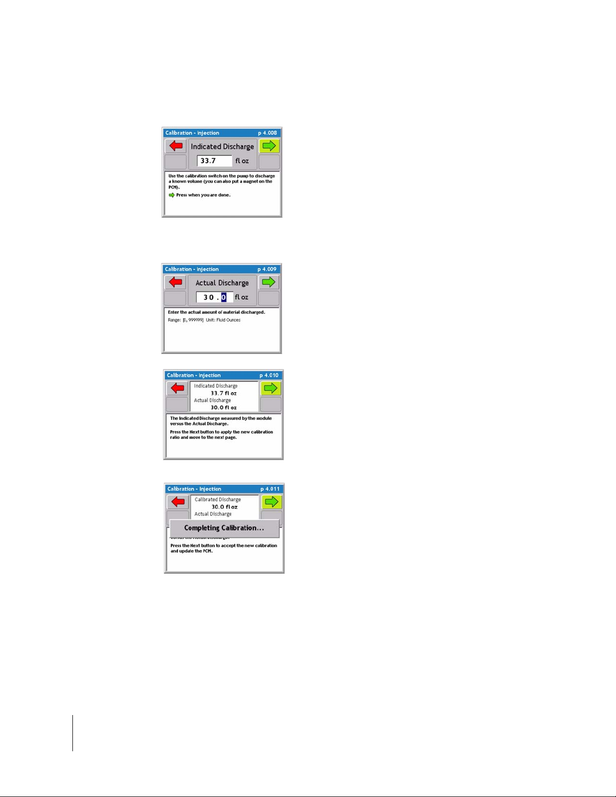
Fieldware for the Legacy 6000
Software Version 2.11
Injection Static Calibration / Continued
4. Place the calibration container under the calibration valve on the pump. Use the Calibration
button on the pump or place a magnet on the
PCM to start discharging product. As product
discharges volume should accumulate on the
Legacy. When a significant amount of material
has been discharged let go of the calibration
button or remove the magnet. Press the green
forward arrow to advance to the next calibration
step.
6. Enter the Actual amount Discharged. This is
the known amount captured in the calibrat ion
container . Press the green for ward arrow to continue to the next calibration step
7. Indicated Discharge Vs. Actual Discharge.
This page is only a information page to show
the operator the Indicated Vs. the Actual. Press
the green forward arrow to automatically reca lculate the calibration number so the two volumes match.
10. When the two volumes match press the
green forward arrow and the Injection calib ra tion procedure is complete.
3-24 Chapter 3 - Real-time Setup
Performing a Calibration
Page 95

Fieldware for the Legacy 6000
Software Version 2.11
Prime Injection System
Priming feature will only appear as an option if Injection has been selected as the Drive type during
PCM setup. Priming is an Injection feature only. Priming the injection system can be done in three
easy steps. Priming the system will take chemical from the injection storage tank directly to the
injection point to ensure chemical is injected instantly upon the start of an application. NOTE:
Injection Calibration must be completed prior to priming for the system to properly prime.
1. Calculate Prime value
Calculate the Prime value using the formula below , this value should be entered during PCM setup
Drive Type Injection (See “Drive Type Settings” on page 2-25.)
Calculating the Prime Value
(Line diameter/2) X 3.1416 X Line length X 0.5541 = Volume in Fluid Ounces
Chapter 3 - Real-time Setup 3-25
Prime Injection System
Page 96

Fieldware for the Legacy 6000
Software Version 2.11
2. Setup System for Priming
Select the Prime button from the ARM launcher page, this will bring up the % Prime page. The
prime page has two buttons (Prime State and Reset Values to Zero.) Prime State provides a
detailed set of values of the priming process. During priming view this page to see the pump priming progress. The zero button will reset values to zero.
Figure 3-8: Setup System for Priming
3. Start Prime
From the prime page each pump is ready to prime. Press th e prime button on the front of the pump
(top button) or place a magnet on the front of the PCM to start the pump. The pump will stop automatically once the pump volume reaches the prime volume. To view the live prime process select
the Prime State button. Repeat this procedure for each pump..
Figure 3-9: Prime and Prime State Button
3-26 Chapter 3 - Real-time Setup
Prime Injection System
Page 97

Fieldware for the Legacy 6000
Software Version 2.11
Reverse Prime Injection System
Reverse Prime does not come standard on the peristaltic injection pump. Reverse Prime can be
added as a feature. Call your local Mid-Tech distributor to order the reverse prime feature using
Part# 54-02015.
Reverse prime works very similar to the priming procedure. Reverse Priming the system will take
chemical from the injection point directly back to the storage tank to save as much chemical as
possible. To Reverse Prime the system use the Prime button from the ARM Launcher page, this
button will only appear as an option if Injection has been selected as the Drive type during PCM
setup. Priming and Reverse Priming is an Injection feature only. Reverse Priming the injection system can be done in two steps if the system has been prope rly p rimed a nd a prime va lue has been
calculated (See “1. Calculate Prime value” on page 3-25.)
Chapter 3 - Real-time Setup 3-27
Reverse Prime Injection System
Page 98

Fieldware for the Legacy 6000
Software Version 2.11
1. Setup Stem for Reverse Priming
Select the Prime button from the ARM launcher page, this will bring up the % Prime page. The
prime page has two buttons (Prime State and Reset Values to Zero.) Prime State provides a
detailed set of values of the priming process. During priming view this page to see the pump priming progress. The zero button will reset values to zero.
Figure 3-10: Setup System for Reverse Prime
2. Start Reverse Prime
From the prime page each pump is ready to rever se prime. Press the Revers e Prime button on the
front of the pump (bottom button) and the pump should start turning. The pump will stop automatically once the pump volume reaches the prime volume. To view the live prime process select the
Prime State button from the prime page.
Figure 3-1 1 : Reverse Prime & Prime State Button
3-28 Chapter 3 - Real-time Setup
Reverse Prime Injection System
Page 99

Fieldware for the Legacy 6000
Software Version 2.11
Job Report Setup
A Job Report contains all the necessary information to build an application report after the job is
completed. Application reports are generated in the Fieldware Map Manager desktop program.
Job Report is accessed from the ARM Launcher page (Figur e 3-12). Select the Job Report t ab and
move to the Main Job Report Page (Figure 3-12). Table 3-3 describes each Job Report menu item.
No PCMCIA Card Selected
If you have the PC Card setting in Console setup set to NO, the Job Report tab will not be an
option on the ARM Launcher page.
Running the Job Report Wizard
The Main job Report Setup page is the page seen when Job Report is first entered (Figure 3-12)
right image. The Job Report page cont ains every setup item in a list. From this list each Job Report
item can be edited individually or the Job Report Setup Wizard can be run. The top item in the list
is the Setup Wizard. To run the Setup Wizard, highlight <Set Up Wizard> in the main list and press
the enter key. The Setup Wizard will walk through the entire Job Report Setup item list.
It is not necessary to fill out any Job Report information in order to start applying products. The Job Report
Information should be filled out if it is desired to write this data to the header of the record file (.RCD).
Figure 3-12: ARM Launcher / Job Report Page
Chapter 3 - Real-time Setup 3-29
Job Report Setup
Page 100

Fieldware for the Legacy 6000
Software Version 2.11
Job Report Detailed Description
Item Description
Wind Speed Enter the observed Wind Speed. Units are based on the Units set in Console
Setup. If no wind speed is to be entered, set this to NO.
Wind Direction Enter the observed Wind Direction from the following directions NE, E, SE, S,
SW, W, NW, N and Not Observed.
Temperature Enter the observed Temperature. Units are based on the Units set in Console
Setup. If no temperature is to be entered, set this to NO.
Current Weather Select the app ropriate weather condition from the following conditions: Sunny,
Cloudy, Partly Cloudy, and Not Observed.
Soil Moisture Select the appropriate Soil Moisture from the following conditions: Dry, Moist,
Wet, and Not Observed.
Soil Texture Select the appropriate Soil Texture from the following textures Fine, Medium
Course, and Not Observed.
Soil Tillage Select the appropriate Soil Tillage from the following conditions: No Till, Min
Till, Conv Till, and Not Observed.
Soil Condition Select the appropriate Soil condition from the following conditions: Good,
Trashy, Smooth, Rough, and Not Observe d.
Crop Name Enter the name of the Crop.
Growth Stage Select the appropriate Growth Stage from the following stages Pre-Plant, Pre-
Emergence, Post Emergence, and Not Observed.
Table 3-3: Job Report Item Descriptions
3-30 Chapter 3 - Real-time Setup
Job Report Setup
 Loading...