

Page 1

F I E L D P I L O T®
I N S TA L L AT I O N M A N UAL
Assisted Steering Hydraulic Installation Manual for
Vehicle Kit Number 91-02305
Fits Only John Deere 9x00 & 9x20
Page 2

Page 3

Page 4

FieldPilot
®
FIELDPILOT®
Copyrights
© 2011 TeeJet Technologies. All rights reserved. No part of this document or the computer programs described
in it may be reproduced, copied, photocopied, translated, or reduced in any form or by any means, electronic or
machine readable, recording or otherwise, without prior written consent from TeeJet Technologies.
Trademarks
Unless otherwise noted, all other brand or product names are trademarks or registered trademarks of their
respective companies or organizations.
Limitation of Liability
TEEJET TECHNOLOGIES PROVIDES THIS MATERIAL “AS IS” WITHOUT WARRANTY OF ANY KIND, EITHER
EXPRESSED OR IMPLIED. NO COPYRIGHT LIABILITY OR PATENT IS ASSUMED. IN NO EVENT SHALL
TEEJET TECHNOLOGIES BE LIABLE FOR ANY LOSS OF BUSINESS, LOSS OF PROFIT, LOSS OF USE OR
DATA, INTERRUPTION OF BUSINESS, OR FOR INDIRECT, SPECIAL, INCIDENTAL, OR CONSEQUENTIAL
DAMAGES OF ANY KIND, EVEN IF TEEJET TECHNOLOGIES HAS BEEN ADVISED OF SUCH DAMAGES
ARISING FROM TEEJET TECHNOLOGIES SOFTWARE.
iv
www.teejet.com
Page 5
FieldPilot
®
PREPARATION
1. Before beginning the installation, thoroughly clean the vehicle to remove dirt and contaminants that might get
into the hydraulic circuit.
2. Park the vehicle on a clean, level oor with adequate clearance to work around.
3. Do not attempt to loosen any hydraulic ttings while the engine is running.
4. Allow the motor and the hydraulics to cool until it is no more than warm to the touch before proceeding.
5. Prior to loosening any hydraulic ttings, be sure to have the appropriate plugs and caps available in order to
limit loss of hydraulic uid from the open ttings.
PREVENT HYDRAULIC SYSTEM CONTAMINATION. It is essential to thoroughly clean hydraulic
system ttings and hose connections prior to disconnecting or removing them. Use a spray cleaner
such as “Brake Clean” to prevent hydraulic system contamination. Note that o-rings used on ORB and
ORFF type ttings may be damaged by solvent cleaners such as “Brake Clean”. If a tting is to be cleaned
internally, the o-ring should rst be removed and cleaned with a berless cloth.
IMPORTANT
WARNING: HOT, HIGH PRESSURE FLUID HAZARD. Hydraulic oil may be hot and under extreme
pressure. To prevent serious injury or death, relieve system pressure and allow the system to cool
before repairing or disconnecting. Wear proper hand and eye protection when searching for leaks,
using wood or cardboard instead of hands. Keep all hydraulic components in good repair.
WARNING: PINCH POINT HAZARD! To prevent serious injury or death, avoid unsafe practice while
manually operating hydraulic steering circuits. Keep others away and stay clear of mechanical steering
linkages.
TO AVOID EXCESS LEAKAGE, DO NOT TURN THE STEERING WHEEL WHILE THE
FITTINGS ON THE MANUAL STEERING VALVE ARE DISCONNECTED.
98-05217 R3
1
Page 6

FieldPilot
®
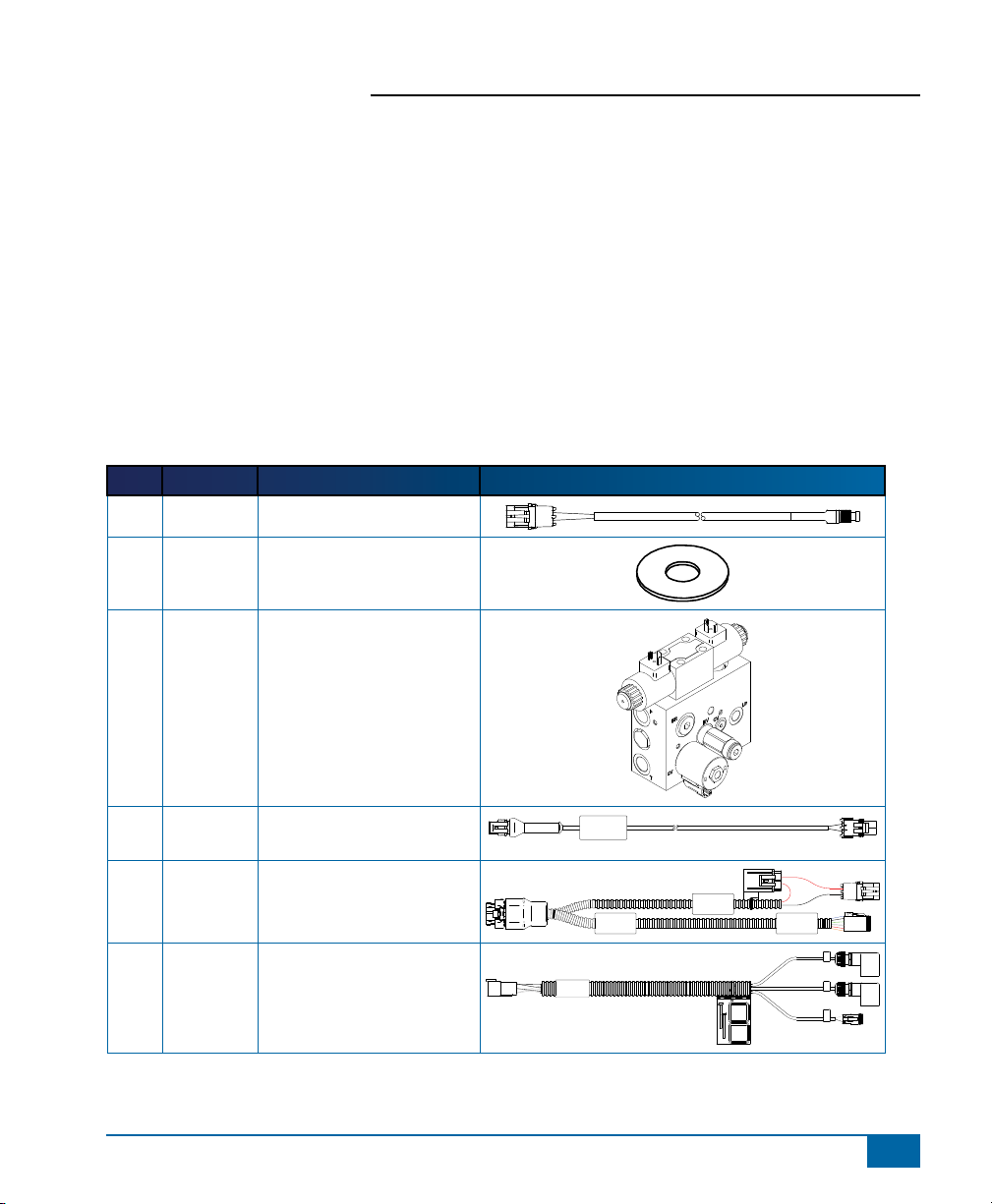
KIT CONTENTS
Unpack the installation kit and identify the required parts.
Item Part Number Description Quantity
A 32-04040 Switch, Engage/Disengage ......................................................................................1
B 350-0037 Washer, Flat - 3/8” SST ...........................................................................................3
C 35-03196 Valve, FieldPilot, PWM, 7.9GPM, CC, w/ Master & Relief .......................................1
D 45-05822 Cable,PSI Switch, 15’, FieldPilot, to 2 Pos WP........................................................1
E 45-07704 Cable, SCM to Power, FieldPilot Valve & Master.....................................................1
F 45-10136 Harness, FieldPilot Valve, A, B, & Master ...............................................................1
G 60-04095 Bolt, Hex- 3/8-16 x 3-3/4” SST .................................................................................2
H 60-04095 Bolt, Hex- 3/8-16 x 1-1/2” SST .................................................................................1
I 60-04099 Set Screw, 10/24 X 3/8”, Cup Point Allen ................................................................1
J 60-07027 Nut, NyLock 3/8-16, SST .........................................................................................3
K 65-05162 Bracket, Hydraulic Block Mount ...............................................................................1
L 68-01152 Hose, Hydraulic - 3/8” x 53”, #8FORF x #8FORF90º ..............................................2
M 68-01170 Hose, Hydraulic - 3/8” x 38”, #8FORF x #6FORF90º ..............................................1
N 68-01256 Hose, Hydraulic - 1/4” x 42”, #6FJIC x #6FORF90º .................................................1
O 68-01257 Hose, Hydraulic - 1/4” x 20”, #6FORF x #6FORF ....................................................1
P 68-01267 Hose, Hydraulic - 3/8” x 49”, #8FORF x #6FORF90º ..............................................1
Q 68-02012 Shuttle Tee ...............................................................................................................1
R 68-02026 Adapter, Hydraulic Run Tee - #8 ORF .....................................................................2
S 68-02071 Adapter, Hydraulic Run Tee - #6 ORF .....................................................................2
T 68-02072 Adapter, Hydraulic 90º - #6MORF x #6FORF ..........................................................1
U 68-02073 Adapter, Hydraulic - #6MORF x #6MORB ...............................................................2
V 68-02080 Adapter, Hydraulic 90º - #6MJIC x #6MORB ...........................................................1
W 68-02110 Adapter, Hydraulic - #6FORF x #6MORB ................................................................1
X 68-02118 Adapter Hydraulic - M14 x 1.5 (6149) x #6MORF ...................................................3
Y 68-02159 Adapter, Hydraulic - #8MORF x #8MORB ...............................................................4
Z 68-02187 Adapter, Hydraulic #6 ORF, GPT (Gauge Port Tee) ................................................1
2
www.teejet.com
Page 7
FieldPilot
AA 68-02119 Adapter, John Deere Shuttle Spacer (Short) (RE58763) .........................................1
BB 68-02120 Adapter, John Deere Shuttle Disc ............................................................................1
CC 68-02161 Adapter, John Deere Shuttle Spacer (Long) (RE213458) .......................................1
DD 90-02472 Kit, Patch Antenna Extension 10’ .............................................................................1
EE 90-50013 Cable Tie Kit, 15 ......................................................................................................1
FF 91-00022 Kit, Articulated Gyro Module ....................................................................................1
GG 91-07011 Steering Wheel Switch Kit .......................................................................................1
HH 98-05217 Installation Manual, John Deere 9X00 & 9X20 ........................................................1
II 16-50016 Pressure Switch .......................................................................................................1
Item Part # Description Illustration
A 32-04040 Switch, Engage/Disengage
B 350-0037 Washer, Flat - 3/8" SST
C 35-02196 Valve, FieldPilot, PWM,
7.9GPM, CC, w/ Master &
Relief
®
D 45-05822 Cable,PSI Switch, 15’,
FieldPilot, to 2 Pos WP
E 45-07704 Cable, SCM to Power,
FieldPilot Valve & Master
F 45-10136 Harness, FieldPilot Valve, A,
B, & Master
45-10136
xx/xx
Cable, PSI Switch
FLDPLT
45-05822
SCM Power I/O
45-07704
DC: xx/xx
Power
Valve Output
A
B
Master
98-05217 R3
3
Page 8
FieldPilot
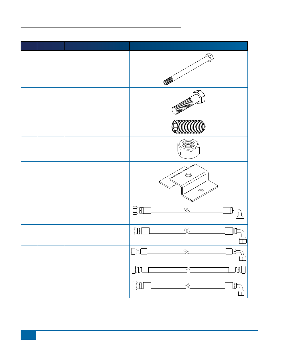
Item Part # Description Illustration
G 60-04089 Bolt, Hex- 3/8-16 x 3-3/4”
H 60-04095 Bolt, Hex- 3/8-16 x 1-1/2”
I 60-04099 Set Screw, 10/24 X 3/8”,
J 60-07027 Nut, NyLock 3/8-16, SST
K 65-05162 Bracket, Hydraulic Block
®
SST
SST
Cup Point Allen
Mount
L 68-01152 Hose, Hydraulic - 3/8” x 53”,
#8FORF x #8FORF90º
M 68-01170 Hose, Hydraulic - 3/8” x 38”,
#8FORF x #6FORF90º
N 68-01256 Hose, Hydraulic - 1/4” x 42”,
#6FJIC x #6FORF90º
O 68-01257 Hose, Hydraulic - 1/4” x 20”,
#6FORF x #6FORF
P 68-01267 Hose, Hydraulic - 3/8” x 49”,
#8FORF x #6FORF90º
4
www.teejet.com
Page 9
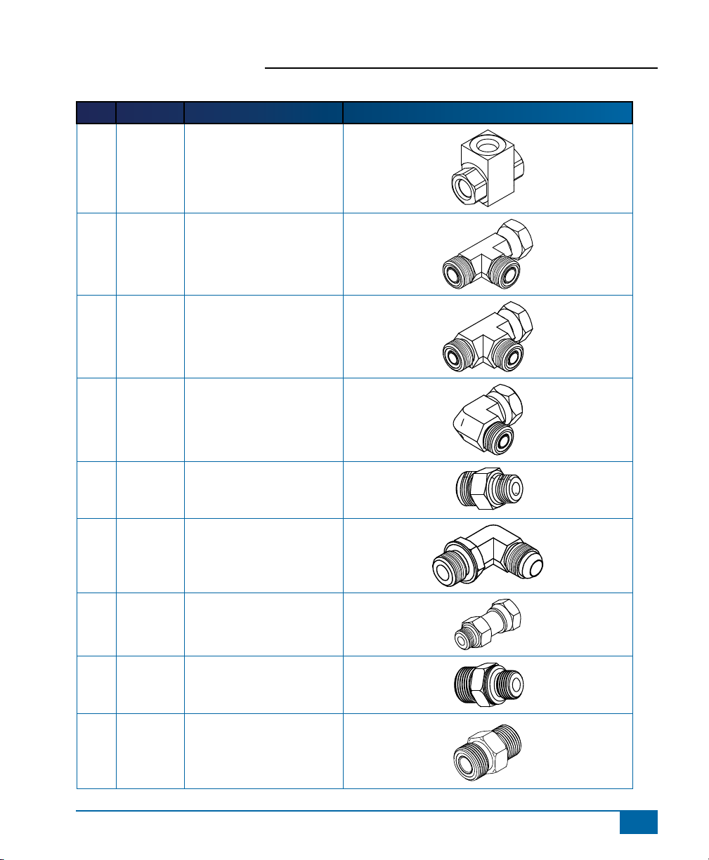
Item Part # Description Illustration
Q 68-02012 Shuttle Tee
R 68-02026 Adapter, Hydraulic Run Tee
- #8 ORF
S 68-02071 Adapter, Hydraulic Run Tee
- #6 ORF
T 68-02072 Adapter, Hydraulic 90º -
#6MORF x #6FORF
FieldPilot
®
U 68-02073 Adapter, Hydraulic -
#6MORF x #6MORB
V 68-02080 Adapter, Hydraulic 90º -
#6MJIC x #6MORB
W 68-02110 Adapter, Hydraulic -
#6FORF x #6MORB
X 68-02118 Adapter Hydraulic - M14 x
1.5 (6149) x #6MORF
Y 68-02159 Adapter, Hydraulic -
#8MORF x #8MORB
98-05217 R3
5
Page 10
FieldPilot
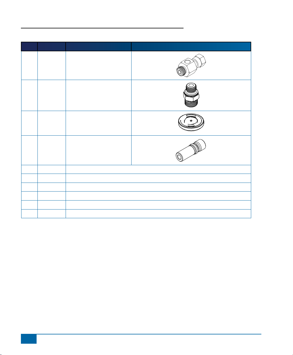
Item Part # Description Illustration
Z 68-02187 Adapter, Hydraulic #6 ORF,
AA 68-02119 Adapter, John Deere Shuttle
BB 68-02120 Adapter, John Deere Shuttle
CC 68-02161 Adapter, John Deere Shuttle
DD 90-02472 Kit, Patch Antenna Extension 10’
EE 90-50013 Cable Tie Kit, 15
FF 91-00022 Kit, Articulated Gyro Module
GG 91-07011 Steering Wheel Switch Kit
HH 98-05217 Installation Manual, John Deere 9X00 & 9X20
II 16-50016 Pressure Switch
®
GPT (Gauge Port Tee)
Spacer (Short) (RE58763)
Disc
Spacer (Long) (RE213458)
6
www.teejet.com
Page 11

Figure 1-1: Hydraulic Diagram - Without Deluxe SCV Cap
L R
Steering Unit
Normal steering
oil source is a
gear pump.
FieldPilot
Tank
®
Existing Hoses
Hoses From Kit
L
B T
L
FieldPilot Valve
Replace plug with
Disc and spacer.
P
N
LS
M
PA
P LS T
Hydraulic distribution block
on the rear of the tractor
Auxiliary
Pump
98-05217 R3
7
Page 12

FieldPilot
®
Figure 1-2: Hydraulic Diagram - With Deluxe SCV Cap
L R
Steering Unit
Normal steering
oil source is a
gear pump.
Tank
Existing Hoses
Hoses From Kit
L
B T
L
FieldPilot Valve
Lift cap on SCV and
insert 10_24 set
screw, replace cap.
P
N
LS
M
PA
P LS T
Hydraulic distribution block
on the rear of the tractor
Auxiliary
Pump
8
www.teejet.com
Page 13

Figure 1-3: Hydraulic Diagram - With Other Function Using the Power Beyond
L R
Steering Unit
Normal steering
oil source is a
gear pump.
FieldPilot
Tank
®
Existing Hoses
Hoses From Kit
L
B T
L
FieldPilot Valve
Original Pressure
Original LS Line
P
N
LS
M
PA
Shuttle
Tee
Q
P LS T
Hydraulic distribution block
on the rear of the tractor
Auxiliary
Pump
98-05217 R3
9
Page 14

FieldPilot
POWER IN
CAN
RS-232
Power/DATA
45-05626
45-05626
Pwr/CAN/Data
Cable
(included with
FieldPilot and
BoomPilot kits)
3A Fuse
8 Pos.
to RS-232
to TJ CAN
(Terminated)
45-05381
DC: xx/xx
C
o
n
n
e
ct
o
t
o
(
+
1
2
v)
45-05381
Battery 12'/3.5m
w/15 Amp Fuses
45-08101 CAN Terminator
CAN
Seat Sensor
Steering
Wheel Sense
GPS Power
GPS In
COM 1
Remote
Engage/Disengage
SCM COM 2
Power
SCM Power I/O
45-07703
DC: xx/xx
Valve Output
78-08061
Steering Control
Module (SCM)
45-07708
SCM Harness
45-07704
SCM Power I/O
Engage / Disengage
32-04020
DC: xx/xx
32-04020
Optional
Footswitch
32-04040
Remote
Engage/
Disengage
Switch
45-10136
Harness
Steering
(A+B)
& Master
45-10136
DC: xx/xx
Steering
Valve
78-08072
Voltage
Regulator
FieldPilot Interface
78-08072
DC: xx/xx
Steering Valve
16-00022: RealView Camera
4 Pos.
8 Pos.
Speed Cable
Camera
45-05617: 20'/6m
45-05618: 60'/18m
Camera Extension Cable
45-05615 4 Pos.
45-05765 8 Pos.
Speed/Sense Cable
5 Pos.
+12V
32-50008
Switch
78-50155 GPS Patch Antenna
Matrix 570G
75-30055
75-30056 w/ClearPath
Kit, RAM Mount w/Suction Cup
90-02349 (Matrix 570G)
90-02700 (Matrix 840G)
Matrix 840G
75-30070
75-30071 w/ClearPath
Matrix
FieldPilot
Optional Accessory
45-05786: 20’/6 m
45-05787: 30’/9 m
Antenna Cable
78-50187
Optional RXA-30 GPS Antenna
65-05226
Kit, Bracket
RXA-30 Antenna
45-08117 CAN Extension Cable 20'/6m
45-07716
Harness TGM
CAN Tee
Tilt Gyro Module
CAN Harness
45-07716
DC: xx/xx
78-08073
Articulated Gyro Module (AGM)
®
Figure 1-4: System Diagram
10
www.teejet.com
Page 15

FieldPilot
INSTALLATION
If there are questions concerning the installation of the FieldPilot system on this vehicle, or due to the
changes in component specications the parts supplied in the kit are not exactly as presented in this
document, please contact your dealer or TeeJet customer service representative for clarication before
installation. TeeJet Technologies is not responsible for misuse or incorrect installation of the system.
NOTE: BE VERY CAREFUL TO ABSOLUTELY SECURE ALL CABLES AND HOSES SO THAT THEY DO NOT
INTERFERE WITH THE MANY MOVING PARTS OF THE MACHINE!
Overview of the Machine
• Most of the FieldPilot system will install near the rear of the machine on the left hand side.
• Pressure, Tank, and LS connections will be at the rear of the machine in the Power Beyond ports of the SCV
stack.
• The steering lines will tee-in near the steering cylinder on the left side of the machine.
• The GPS will mount near the front of the machine on the hood.
NOTE: All references to left and right are stated as if the user is seated in the driver’s seat.
Figure 1-5: Preparing the FieldPilot Valve
®
GPS
Steering Line
Connections
Hydraulic
Connections
FieldPilot
Valve
Cable
Entrance
98-05217 R3
11
Page 16

FieldPilot
Specic Cautions
The two adapters (U & X) look almost identical and can be easily confused with each other. Adapter (X) has
metric threads and can be identied by the raised O-ring ange as indicated in the picture. If adapter (X) has a
metal washer included, it must be removed before installing adapter (X).
Figure 1-6: Preparing the FieldPilot Valve
®
U
X
1. PREPARE THE FIELDPILOT VALVE
Install adapter (Y) in the A, B, P and T ports of the FieldPilot valve. Install adapter (V) in LS port.
Figure 1-7: Preparing the FieldPilot Valve
Y
Y
V
12
www.teejet.com
V
Page 17

FieldPilot
2. INSTALL THE FIELDPILOT VALVE BRACKET
Locate the holes on the left side of the rear portion of the tractor as shown. Select the hole shown and mount the
valve bracket (K) using bolt (H), washer (B) and nut (J).
Figure 1-8: Installing the Mounting Bracket for the FieldPilot Valve
K
H, B, J
3. MOUNT THE FIELDPILOT VALVE
Use bolts (G), washers (B) and nuts (J) to mount the FieldPilot valve (C) to the bracket (K). Mount the valve
with the electronic connections up, the Pressure, Tank and Load sense adapters should be facing the rear of the
tractor and the A and B adapter should be facing the front of the tractor.
®
Figure 1-9: Mounting the FieldPilot Valve
G, B, J
98-05217 R3
13
Page 18

FieldPilot
®
4. PREPARE LEFT AND RIGHT STEERING HOSE CONNECTIONS
Locate the hose connections from the left steering cylinder near the pivot point in the middle of the tractor.
Remove the hoses to the left of the steering cylinder one at a time and install run tee (R). Reconnect the original
hoses to the run of the tees.
Figure 1-10: Preparing the Left and Right Steering Hose Connections
R
5. INSTALL LEFT AND RIGHT STEERING HOSES
Using hoses (L) install them between the A and B ports on the FieldPilot valve and the branch of the tees
installed in steering cylinder lines near the pivot point of the tractor.
Figure 1-11: Installing the Left and Right Steering Hoses
L
14
www.teejet.com
L
L
Page 19

FieldPilot
6. DETERMINE VERSION OF SCV COVER/CAP
There are four types of SCV covers or caps used on this series of John Deere tractor. They are designated as:
V1, V2, V3, and Deluxe – see pictures that follow.
It is important to know which SCV cover is on your machine, because the SCV cover version determines if you
use the Spacer (AA or CC) and disc (BB) or the Set Screw (I) in the LS port.
Figure 1-12: Parts
CC
AA
I
• V1: Use part (AA & BB)
BB
• V2: Use part (CC & BB)
• V3: Use part (CC & BB)
• Deluxe: Use part (I)
®
98-05217 R3
15
Page 20

FieldPilot
®
Figure 1-13: V1: Use part (AA & BB)
Figure 1-14: V3: Use part (CC & BB)
Figure 1-15: V2: Use part (CC & BB)
Figure 1-16: Deluxe: Use part (I)
(I) mounts under cover
16
www.teejet.com
Page 21

FieldPilot
7. PREPARE THE SCV STACK
Version V1
Remove the two plugs or test ports from the T and P ports. Install adapters (X) in the T & P ports. Remove the
plug from the LS port, and insert shuttle disc (BB) in the LS port. Then insert with threaded end up the spacer
(AA) into the same LS port. Finally install adapter (X) in the LS port.
Figure 1-17: Preparing the SCV Stack
®
X
AA
BB
BB, AA
then X
98-05217 R3
17
Page 22

FieldPilot
Version V2 & V3
Remove the two plugs or test ports from the T and P ports. Install adapters (X) in the T & P ports. Remove the
plug from the LS port, and insert shuttle disc (BB) in the LS port. Then insert with threaded end up the spacer
(CC) into the same LS port. Finally, install adapter (X) in the LS port.
Figure 1-18: Preparing the SCV Stack
®
X
CC
BB, CC
then X
BB
BB, CC
then X
X
18
www.teejet.com
Page 23

FieldPilot
Version Deluxe
Remove the plugs or test ports from the T, LS, and P ports. Install adapters (X) in the T, LS & P ports. Remove
the three bolts holding the SCV cover and remove the cover from the SCV stack. Install set screw (I) into the
threaded port as indicated. Then reinstall the cover on the SCV stack.
Figure 1-19: Preparing the SCV Stack
®
Remove
X
Remove
bolts
X
Remove
I
I
98-05217 R3
19
Page 24

FieldPilot
Power Beyond is Used By Other Functions
If the LS Power Beyond function is already being used by some other application, then the shuttle disc (BB) and
the spacers (AA or CC) or the set screw (I) are already installed and you will need to install a shuttle tee (Q).
Prepare the shuttle tee (Q) by installing adapters (U) and (W) as shown. Disconnect the hose from the LS port
and install the prepared shuttle tee. Reconnect the original LS hose to one port of the shuttle tee. The FieldPilot
LS will connect to the other port of the shuttle tee.
If there are hoses already connected to the P or T ports of the SCV stack then disconnect those hoses and install
run tees (S). Then reconnect the original P & T hoses to the run of the tees. The FieldPilot hoses will connect to
the branch of the run tees.
On some applications there may be a hose from a tee on the LS port to the tank port. This hose has an orice
plate in one end. Its purpose is to bleed off pressure from the LS line being used the other function. Make sure
that this drain to tank remains with LS line when the LS line is moved to the shuttle tee (Q). Additional hose (O)
is included in case the original LS drain hose is not long enough or if it was a hard steel line. Adapter (T) can be
used as needed to make the installation of the shuttle tee or run tees easier.
Figure 1-20: Preparing the SCV Stack
®
Q
W
Original LS Hose
20
www.teejet.com
UU
NOTE: The two adapters (U & X) look almost
identical and can be easily confused
with each other. Adapter (X) has metric
threads and can be identified by the
raised o-ring flange.
Hose with orice plate
FieldPilot LS Hose
FieldPilot Tank Hose
FieldPilot Pressure Hose
S
Page 25

FieldPilot
®
8. INSTALL THE TANK HOSE
Attach the 90° end of the (P) hose to the T port of the hydraulic stack, and the other end to the T port on the
FieldPilot Valve.
Figure 1-21: Installing the Tank Hose
P
P
9. INSTALL PRESSURE HOSE
Attach the 90° end of hose (M) to the P port on the hydraulic stack. Connect the straight end of the hose to the P
port on the FieldPilot Valve.
Figure 1-22: Installing the Pressure Hose
M
M
98-05217 R3
21
Page 26

FieldPilot
®
10. INSTALL THE LS HOSE
Attach the 90° end of the hose (N) to the LS port on the hydraulic stack. Connect the other end to the LS port on
the FieldPilot valve.
Figure 1-23: Installing the LS Hose
N
N
11. INSTALL THE VALVE CONTROL CABLE
The valve cable exits the cab in the left rear through a grommet under the rear cab window. Install the electronic
valve control cable (F) at the FieldPilot valve by attaching the DIN connectors to the individual coils. Attach the
two position DT connector to the master solenoid.
NOTE: If the vehicle automatically steers the wrong way when it is tested, exchange the connector positions.
Route this cable through the rear window of the cab and forward along the oor. Secure with tie wraps as
necessary.
Figure 1-24: Installing the Valve Control Cable
22
www.teejet.com
NOTE: Be sure to leave enough slack in this cable
for the vehicle to articulate around its pivot
point without putting a strain on the cable, or
damage to the cable may result.
Page 27

FieldPilot
12. INSTALL THE PRESSURE SWITCH, HYDRAULIC ADAPTER,
AND CABLE
The pressure switch and adapter will install in the LS line from the orbital. Follow the LS line from the orbital to
where it connects to the priority valve underneath the machine. Disconnect the LS line and install adapter (Z).
Then install the Pressure Switch (II) into adapter (Z). Next, connect cable (D) from the pressure switch to the
SCM harness cable labeled STEERING WHEEL SWITCH.
Figure 1-25: Installing the Pressure Switch, Hydraulic Adapter, and cable
®
Install Adapter Z here
98-05217 R3
23
Page 28

FieldPilot
®
13. INSTALL STEERING DISENGAGE SENSOR
The steering disengage kit (GG) is used to automatically disengage FieldPilot when the steering wheel is turned.
The sensor must be mounted so that it has a 1/8” clearance from the magnets. There are two mounting options:
1. Using self tapping screws, mount the aluminum bracket from (GG). Bend it as shown and mount the magnets
to the spokes of the steering wheel. Install the sensor and ensure the sensing tip passes over the magnets with
a clearance of 1/8”.
2. Remove the shrouds around the steering base. Locate the steering shaft and attach 3 magnets to the shaft,
then install the bracket and sensor as shown so that there is a clearance of 1/8” between the magnets and
sensor.
Route the cable and ensure it will not get tangled in any moving components. Connect the sensor to the SCM
harness.
Figure 1-26: Installing the Steering Disengage Switch (Kit 91-07011)
24
www.teejet.com
Page 29

FieldPilot
®
14. INSTALLATION OF ENGAGE/DISENGAGE SWITCH
Connect item (A) to the connector on the SCM harness labeled Remote Engage/Disengage. Install the push
button in a location that is easily accessible during operation of the machine. This switch (A) is not required if the
optional foot switch 32-04020 is used.
Figure 1-27: Engage/Disengage Switch
15. RECOMMENDED ELECTRONICS INSTALLATION
The Steering Control Module (SCM) should be mounted securely to the oor of the cab as far forward in the
cab as possible. The control console can be mounted to the operator’s preference. The GPS antenna should be
mounted near the nose of the vehicle on a metal surface of at least 4” square.
The Articulated Gyro Module (AGM) should be mounted towards the rear of the vehicle on a at surface that
is horizontal to the ground. Plug the CAN extension cable to the AGM Harness (45-07716) as well as the CAN
terminator. Route the other end of the CAN extension cable towards the cab and connect to the CAN on the SCM
harness.
Figure 1-28: Recommended Electronics Installation
GPS
AGM
98-05217 R3
25
Page 30

FieldPilot
®
16. VERIFY OPERATION OF HYDRAULICS AND SET THE STEERING
CONTROL RATE
Clean and pick up the area around the vehicle and make certain that it is safe to operate. Start the engine and
check hydraulic connections for leaks. Rotate the steering wheel from one extreme to the other and back to
center, check for leaks. While steering through the extremes of movement, check the cables and hoses for wear
points and strain, adjust as necessary.
The nal oil ow rate adjustment is accomplished through the Matrix console. The
target lock to lock time is 8 seconds and the valve frequency is 175. Refer to the Matrix
manual for further instructions.
NOTE: To activate the manual overrides, a tool such as a small screwdriver or allen wrench must be inserted into
the end of the coil to depress the override button.
WARNING: PINCH POINT HAZARD! To prevent serious injury or death, avoid unsafe practice while
manually operating hydraulic steering circuits. Keep others away and stay clear of mechanical steering
linkages.
17. COMPLETE ELECTRONIC INSTALLATION
Refer to the owner’s manual supplied with the automated steering system to complete the electronic installation
and setup.
26
www.teejet.com
Page 31

Page 32

F I E L D P I L O T®
I N S TAL L AT I O N M A N U A L
A series of equipment-specic hydraulic installation kits have been
developed to work in conjunction with your assisted steering system. This
kit contains the necessary components and instructions to install assisted
steering hydraulics on the John Deere 9x00 & 9x20. Please review this
manual thoroughly before beginning the installation process.
1801 Business Park Drive
Springeld, Illinois 62703 USA
Tel: (217) 747-0235 • Fax: (217) 753-8426
www.teejet.com
98-05217 R3
© TeeJet Technologies 2011
 Loading...