

Page 1

F I E L D P I L O T®
U S E R M A N U A L
Assisted Steering Hydraulic Installation Manual for
Vehicle Kit Number 91-02701 & 91-02702
Fits Only John Deere Tractor Models:
8x00/8x10/8x20/8x30/8xxx-R Series
with factory EHPS Steering Valve
Page 2

FieldPilot
®
FIELDPILOT®
Copyrights
© 2010 TeeJet Technologies. All rights reserved. No part of this document or the computer programs
described in it may be reproduced, copied, photocopied, translated, or reduced in any form or by any
means, electronic or machine readable, recording or otherwise, without prior written consent from TeeJet
Technologies.
Trademarks
Unless otherwise noted, all other brand or product names are trademarks or registered trademarks of their
respective companies or organizations.
Limitation of Liability
TEEJET TECHNOLOGIES PROVIDES THIS MATERIAL “AS IS” WITHOUT WARRANTY OF ANY KIND,
EITHER EXPRESSED OR IMPLIED. NO COPYRIGHT LIABILITY OR PATENT IS ASSUMED. IN NO
EVENT SHALL TEEJET TECHNOLOGIES BE LIABLE FOR ANY LOSS OF BUSINESS, LOSS OF PROFIT,
LOSS OF USE OR DATA, INTERRUPTION OF BUSINESS, OR FOR INDIRECT, SPECIAL, INCIDENTAL,
OR CONSEQUENTIAL DAMAGES OF ANY KIND, EVEN IF TEEJET TECHNOLOGIES HAS BEEN
ADVISED OF SUCH DAMAGES ARISING FROM TEEJET TECHNOLOGIES SOFTWARE.
WARNING: PINCH POINT HAZARD! To prevent serious injury or death, avoid unsafe practice
while manually operating hydraulic steering circuits. Keep others away and stay clear of
mechanical steering linkages.
ii
www.teejet.com
Page 3

FieldPilot
KIT CONTENTS
Unpack the installation kit and identify the required parts.
Item Part Number Description Quantity
A 32-04040 Switch, Engage/Disengage ......................................................................................1
B 45-05396 Power Cable, Cab Access .......................................................................................1
C 45-05626 Cable, Main Matrix Console .....................................................................................1
D 45-05801 Cable, John Deere - EHPS to TeeJet ......................................................................1
E 45-07718 Harness, SCM, Short ...............................................................................................1
F 45-08101 Terminator, CAN Male, WP ...................................................................................... 1
G 60-04141 Screw, Socket Head Cap, M5-0.8 x 25mm SST ......................................................2
H 60-05042 Spacer, 3/8” OD, 1/2” Long, #12 Screw, Aluminum .................................................2
I 78-05080 Interface, EHPS to SCM ..........................................................................................1
J 78-05083 Interface, John Deere - Steering Sensor to SCM (disengage) ................................1
K 78-05085 Interface, John Deere Wheel Sensor 1, John Deere 10/20/30/R-Series .................1
L 78-05086 Interface, John Deere Wheel Sensor 2, John Deere 10/20/30/R-Series .................1
M 78-05087 Interface, John Deere Angle Sensor, John Deere 10/20/30 Series .........................1
M 78-05084 Interface, John Deere Angle Sensor, John Deere R-Series 8 POS .........................1
N 78-08061 Steering Control , Module, FieldPilot IV ..................................................................1
O 90-50013 Cable Tie Kit, 15 ......................................................................................................1
P 91-07013 Kit, Dust Caps, John Deere EPHS 8xxx Series .......................................................1
Q 98-05227 Installation Manual John Deere w/Factory Valve .....................................................1
®
NOTE: Which (M) is included depend upon which kit was ordered.
www.teejet.com
1
Page 4
FieldPilot
Matrix 840G
®
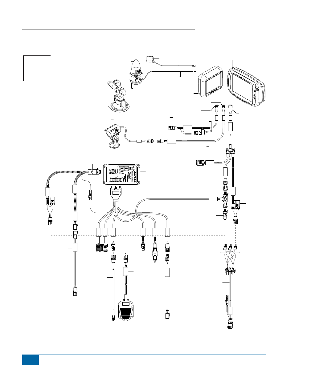
Figure 1-1: System Diagram
Matrix
FieldPilot
Optional Accessory
Power
Optional RXA-30 GPS Antenna
Kit, RAM Mount w/Suction Cup
90-02349 (Matrix 570G)
90-02700 (Matrix 840G)
16-00022: Camera
78-05080
SCM Power I/O
SCM Power I/O
78-08050
DC: xx/xx
Valve Output
SCM COM 2
GPS In
COM 1
Engage/Disengage
Remote
78-50187
45-07718
SCM Harness
65-05226
Kit, Bracket
RXA-30 Antenna
45-05615 4 Pos.
45-05765 8 Pos.
Speed/Sense Cable
78-08061
Steering Control
Module (SCM)
GPS Power
78-50155 GPS Patch Antenna
45-05786: 6 m
45-05787: 9 m
Antenna Cable
Matrix 570G
75-30055
75-30056 w/ClearPath
Speed Cable
Camera
Camera Extension Cable
to RS-232
Wheel Sense
Seat Sensor
Steering
32-50008
Switch
+12V
45-05617: 20'
45-05618: 60'
CAN Terminator
5 Pos.
4 Pos.
8 Pos.
RS-232
45-08101
CAN
75-30070
75-30071 w/ClearPath
Power/DATA
45-05626
45-05626
Power/CAN/Data
Cable
(included with
FieldPilot and
BoomPilot kits)
CAN
POWER IN
8 Pos.
TJ CAN
(Terminated)
3A Fuse
2
www.teejet.com
45-05801
Harness
Steering
Steering
45-05801
to Factory Valve
32-04040
Remote
Engage/
Disengage
Switch
Power Cable
Power Cable
Power Cable
32-04020
32-04020
DC: xx/xx
Engage / Disengage
Optional
Footswitch
78-05083
78-05083
Disengage
Disengage Interface
Battery 12' w/15Amp Fuses
45-05396
Switched +12v
45-05396
DC: xx/xx
to Steering Wheel Sensor
to Power Plug in Cab
Page 5
FieldPilot
INSTALLATION
If there are questions concerning the installation of the FieldPilot system on this vehicle, or due to
the changes in component specications the parts supplied in the kit are not exactly as presented
in this document, please contact your dealer or TeeJet Customer service representative for
clarication before installation. TeeJet Technologies is not responsible for misuse or incorrect installation of
the system.
NOTE: BE VERY CAREFUL TO ABSOLUTELY SECURE ALL CABLES AND HOSES SO THAT THEY
DON’T INTERFERE WITH THE MANY MOVING PARTS OF THE MACHINE!
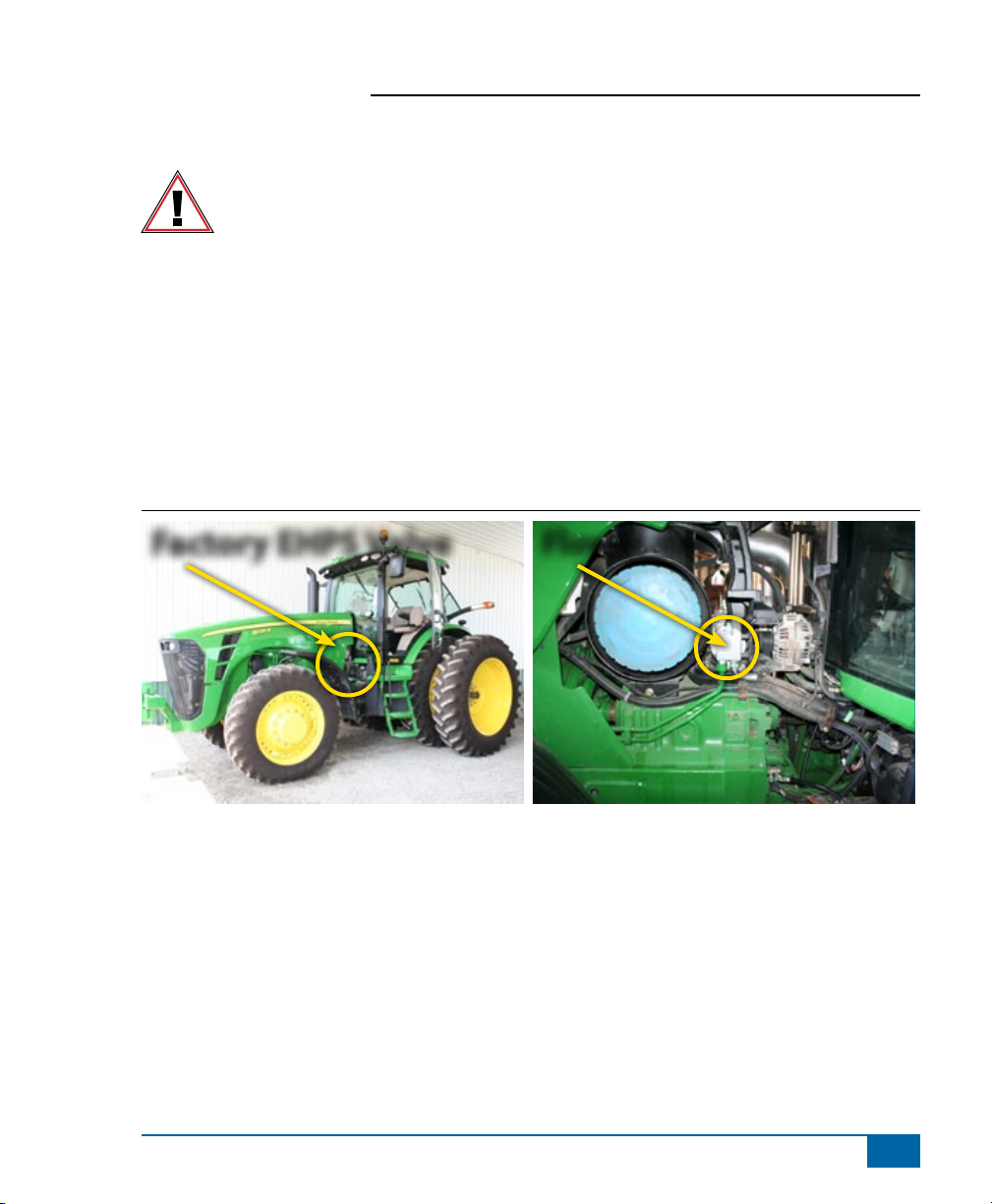
Overview of the Machine
• The factory EHPS valve is located under the front of the cab.
• The steering owmeter (non-ILS machines) is located on the left side of engine.
NOTE: All references to left and right are stated as if the user is seated in the driver’s seat.
Figure 1-2: Overview of the Machine
®
Factory EHPS Valve
Flowmeter
www.teejet.com
3
Page 6

FieldPilot
®
1. INSTALL SPACERS ON STEERING FLOWMETER SENSOR
Non-ILS only
On non-ILS machines, there will be hydraulic owmeter. The two spacers (G) will be installed on the
owmeter sensor. To gain access to the owmeter sensor the owmeter may need to be partially removed
(depends upon tractor model). First remove the cover from the air cleaner. Disconnect the steel line from
the owmeter and remove the two bolts mounting the owmeter. Then the owmeter may be slid out and
rotated to gain access to its sensor. Using a 4mm hex wrench remove the two screws holding the sensor.
Then use screws (H) to install the spacers (G) under the sensor as shown. Slide the owmeter back into its
mounting location and reinstall the mounting bolts. Then reconnect the steel line to the owmeter.
Figure 1-3: Install Spacers On Steering Flowmeter Sensor
Flowmeter
Remove Bolts
Disconnect Sensor
4
www.teejet.com
Page 7

FieldPilot
®
Insert spacers
here
G & H
G & H
G
H
www.teejet.com
5
Page 8

FieldPilot
®
2. INSTALL ANGLE SENSOR INTERFACE ILS ONLY
Tractors with ILS will use a steering angle sensor instead of the steering owmeter. There will be a connector
for the sensor on the left side of the machine along the frame just in front of the cab. Disconnect at that
location and install interface (M) in the connector going towards the cab. Then install the corresponding dust
cap from kit (P) in the other connector. The R-Series connector differs from the 8x10/20/30 connector.
Figure 1-4: Install Angle Sensor Interface
M
Dust Cap
Commect M here
6
www.teejet.com
Page 9

FieldPilot
®
3. INSTALL STEERING SENSOR INTERFACES
The JD tractors have two steering sensors on the steering shaft in the cab. The connectors for these sensors
will need to be disconnected and Interfaces (K & L) will need to be installed. It does not matter which
interface, (K) or (L), is connected to which connector. On some models the connectors are located on the
right side of the steering column. Other models have the connectors on the left side. Remove the necessary
panels from the steering column and disconnect the sensors. Install the appropriate dust cap from kit (P) on
one of the sensor connectors. The other steering sensor will be used in next step.
Figure 1-5: Install Steering Sensor Interfaces
JD 8330
Install Dust
Cap
K
L
JD 8225R JD 8225R
Steering Sensor
Connection
www.teejet.com
7
Page 10

FieldPilot
®
4. INSTALL STEERING DISENGAGE INTERFACE
Using the remaining unused steering sensor connector, connect interface (J). It to the SCM cable labeled
Steering Wheel Sense. Secure all cables so that they will not interfere with the steering shaft.
Figure 1-6: Install Steering Disengage Interface
Connect J here
Connect J here
8
www.teejet.com
Page 11

FieldPilot
5. INSTALL THE STEERING CONTROL MODULE SCM AND
HARNESSES
The SCM (N) should mount securely to the oor of the cab with the arrows pointed forward and as level as
possible. Connect harness (E & I) to the SCM. Then connect together the single position connectors on
(E & I). The are labeled FAULT.
Figure 1-7: Install The Steering Control Module (SCM) and Harnesses
N
N
®
www.teejet.com
9
Page 12

FieldPilot
®
6. INSTALL STEERING CABLE TO EHPS VALVE
Locate the JD EHPS valve. Disconnect the cable from it and install dust cap from kit (P) on cable. Then
route cable (D) from the JD EHPS valve under the cab and into the cab through the rear window. Connect
to SCM harness (I).
Figure 1-8: Install Steering Cable To EHPS Valve
Disconnect
10
www.teejet.com
Page 13

FieldPilot
®
P
D
D
D
www.teejet.com
11
Page 14

FieldPilot
®
7. INSTALL GPS ANTENNA & CONTROL CONSOLE
The GPS antenna should be mounted on top of the cab as far forward as possible on a metal surface of at
lease 4” square. The control console can be mounted in the cab to preference of the operator.
Figure 1-9: Install GPS Antenna & Control Console
GPS
Console
8. INSTALLATION OF ENGAGE/DISENGAGE SWITCH
Connect item (A) to the connector on the SCM harness labeled Remote Engage/Disengage. Install the push
button in a location that is easily accessible during operation of the machine. This switch (A) is not required
if the optional foot switch 32-04020 is used.
Figure 1-10: Engage/Disengage Switch
12
www.teejet.com
Page 15

FieldPilot
9. SPECIFIC CONSOLE SETTINGS
The Valve Frequency must be set to 999.
The target lock to lock time is 5 seconds which is accomplished by adjusting the Maximum Duty Cycle
setting in the Matrix console.
Adjust as needed the other FieldPilot settings in the Matrix console to obtain the best performance.
WARNING: PINCH POINT HAZARD! To prevent serious injury or death, avoid unsafe practice
while manually operating hydraulic steering circuits. Keep others away and stay clear
of mechanical steering linkages.
®
www.teejet.com
13
Page 16

F I E L D P I L O T®
U S E R M A N U A L
A series of equipment-specic installation kits have been developed to
work in conjunction with your assisted steering system. This kit contains
the necessary components and instructions to install assisted steering on
the John Deere Tractor Models: 8x00/8x10/8x20/8x30/8xxx-R Series with
factory EHPS Steering Valve. Please review this manual thoroughly before
beginning the installation process.
1801 Business Park Drive
Springeld, Illinois 62703 USA
Tel: (217) 747-0235 • Fax: (217) 753-8426
www.teejet.com
98-05227 R0
© TeeJet Technologies 2010
 Loading...