

Page 1

Installation
and Operating Instructions
SkyStar1
DVB PCI Sat-Card
0000/4092
Page 2

Features
> Reception of digital satellite TV (DVB) and radio programs on your PC
> Record/Playback - Storing of DVB satellite programs in MPEG2 format (video+audio)
on your hard disk
> Teletext reception and display
> High-speed DVB Internet access or reception of IP-push-services (Multicast) with
transmission rates of up to several MBit/s
Special features
> Simple installation with plug & play
> Together with a digital compliant satellite reception antenna the whole spectrum of
digital video broadcasting (DVB) can be used
> Common Interface, that virtually allows the reception of almost all encoded pay-TV
programs with the corresponding additional module
> Fast image data transfer via PCI-Bus, no cable connection to graphic card
> Image reproduction with continuous zoom in Windows window
> Image display up to max. 768x576 for PAL/DSECAM
> Full Frame (without television frame, TV-screen mode)
> Creates separate frequency lists
> Automatic fast station search
> Storage of station specific and general settings
> Background search for teletext pages (VTX)
> Direct VTX page selection by clicking on page numbers in the text
> Storage and printing of VTX pages
> Extensive configuration options for SAT reception (e.g. DiSEqC)
System requirements
To operate this PC card your PC needs to meet the following minimum requirements for hard
and software:
> PC with Pentium processor 166 or higher
> a free busmaster PCI slot
> at least 32 MB RAM
> at least 32 MB free hard disk storage
> a PCI or AGP graphic acceleration card which can create at least 800x600 image
points in High Color (16 Bit) or True Color (24 or 32 Bit) mode; a corresponding moni-
tor; a mouse
> active speakers or sound card
> a CD-ROM drive (needed for software installation), Microsoft Windows 95 or Microsoft
Windows 98
> DirectX 5 or higher
> Microsoft Internet Explorer 4.01
Furthermore, the card needs to be connected to a satellite reception antenna or to a satellite
reception system which both can receive digital satellite signals (DVB-S). The connecting
cable needs to be equipped with a common F-connector.
2
Page 3

Table of contents
Features . . . . . . . . . . . . . . . . . . . . . . .2
Special features . . . . . . . . . . . . . . . . . .2
System requirements . . . . . . . . . . . . . .2
Table of contents . . . . . . . . . . . . . . . . .3
Card connectors . . . . . . . . . . . . . . . . .4
1 Installation of the DVB PCI Sat card . . .5
1.1 Installing the DVB PCI Sat card . . . . . . . . . . . . . . . . . . . . .5
1.2 Installation of the DVB PCI Sat software . . . . . . . . . . . . . . .6
2 Loading of applications . . . . . . . . . . . .7
2.1 Switching control bars on and off . . . . . . . . . . . . . . . . . . . .8
2.2 Menu Program List . . . . . . . . . . . . . . . . . . . . . . . . . . . . . . .9
3 Adjustment to your Satellite Reception System 10
4 Searching New Channels . . . . . . . . . . . .12
4.1 Window Transponder Scan . . . . . . . . . . . . . . . . . . . . . . . . .12
4.2 Window Automatic Transponder Scan . . . . . . . . . . . . . . . . .14
5 Operation . . . . . . . . . . . . . . . . . . . . . .15
5.1 Control Bar Video . . . . . . . . . . . . . . . . . . . . . . . . . . . . . . . .15
5.2 Control Bar Audio . . . . . . . . . . . . . . . . . . . . . . . . . . . . . . . .16
5.3 Control Bar Program lnfo . . . . . . . . . . . . . . . . . . . . . . . . . .16
5.4 Control Panel Program List . . . . . . . . . . . . . . . . . . . . . . . . .17
5.5 DVB Teletext Application . . . . . . . . . . . . . . . . . . . . . . . . . . .18
5.6 Record/Playback . . . . . . . . . . . . . . . . . . . . . . . . . . . . . . . .19
6 DVB Data Services . . . . . . . . . . . . . . . .20
6.1 Select a Service . . . . . . . . . . . . . . . . . . . . . . . . . . . . . . . . .22
6.2 Index Card State / Tuner . . . . . . . . . . . . . . . . . . . . . . . . . .22
6.3 Index Card DiSEqC / LNB . . . . . . . . . . . . . . . . . . . . . . . . .24
6.4 Index Card Filter . . . . . . . . . . . . . . . . . . . . . . . . . . . . . . . . .25
6.5 Index Card Filter Statistics . . . . . . . . . . . . . . . . . . . . . . . . .27
7 Technical Data . . . . . . . . . . . . . . . . . . .28
3
Page 4
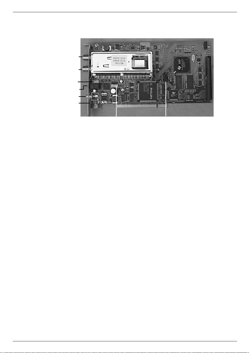
Card connectors
LNB
J8
Loop through
J3
Audio Line Out
CVBS
D9
J4
LNB
F-Connector, for connection to satellite reception system
Loop through
F-Connector, loop through for satellite reception signal, for example for analogue Sat-TV
card; is only supported when D9 is equipped.
Audio Line Out
3.5 mm jack, analogue audio out signal, for the connection of sound-card (Line In) or active
speakers
CVBS
Cinch, Composite Video out signal, for the connection of a TV set or VCR
J3
CD-ROM audio loop through out, for internal connection to sound card (CD ROM Audio In),
J4
CD-ROM Audio loop through in, for internal connection to analogue audio out of CD-ROM
drive
J2, J8
Reserved for future extensions
Cl
Connector for Common Interface Module
J2
CI
4
Page 5

1. Installation of the DVB PCI Sat card
The manufacturer takes no liability for damages, caused by wrong installation of a prefabricated device.
Contact a qualified computer expert if you are not sure with the installation of the card or if
unexpected problems arise.
Caution !!!
When power is switched on during the installation there is the possibility
of an electroshock !!!
In addition, the system components and the DVB PC card might be damaged.
The manufacturer is not responsible for any possible data loss or other damages in connection with the operation of the DVB PC card.
1.1 Installing the DVB PCI Sat card
1. Before you start the installation of the PC card, please make sure that:
> Windows 95 or Windows 98 is installed and configured
> Microsoft Internet Explorer 4.01 is installed
> DirectX 5 or higher is installed
2. Please, close Windows and turn the computer off.
Before doing any work on the hardware remove the power supply of
your computer first and then statically unload your body by touching
an earthed, unvarnished par t of your computer casing.
3. Remove the casing cover of your computer. If necessary see the instructions manual.
4. Choose a free busmaster PCI slot. Most computers are equipped with busmaster
PCI slots.
5. Remove the metal cover of the chosen empty PCI slot. If necessary, connect the CDROM Audio In (J4) of the DVB PC card with the analogue Audio Out of the CD-ROM
drive.
6. If necessary, connect the CD-ROM Audio Out (J3) of the DVB PC card with the analogue CD-ROM Audio In of the sound card.
7. Insert the PC card in the slot.
Make sure the card fits tightly.
8. Secure the card with the screw of the removed metal slot cover and replace the
cover of the computer casing.
9. Connect your satellite reception system with the LNB In socket (upper i.e. outward
F-connector) of the PC card.
10. If needed connect the Audio-Line-Out of the PC card with the Line-In of the sound
card i.e. with the active speakers.
Now, you can install the drivers and application software for the
DVB PCI Sat card.
5
Page 6

Installation of the Common Interface (CI)
With an optional CI module case, a CI module (PC card) and an activated smartcard you
can also receive and decode encoded DVB programs (pay-TV).
The CI module case is to be installed via the provided connector CI (see fig. 1, Card
connectors) with help of the enclosed ribbon cable (connector is safe against mix-up).
1.2 Installation of the DVB PCI Sat software
After you have successfully installed the DVB PCI Sat card in your computer like described
under 1.1 you can install the drivers for your DVB PCI Sat card as follows:
1.2.1 Installation of the driver for Windows 95 and Windows 98
1. Switch your computer on.
2. When Windows is started it automatically recognizes the new hardware and asks you
to install the driver.
3. Windows asks you for the driver files. Please, insert the enclosed CD-ROM into your
CD-ROM drive and choose the start folder (containing the file ttdvb.inf).
Follow the instructions of the installation program. For a complete installation you
might also need the Windows installation CD-ROM. All driver files needed for the
installation are located in the sub-file Driver.
4. After the driver is installed, you might be asked to please turn off the computer and
reboot it again. If not, you can continue with the installation of the application software.
1.2.2 Installing the DVB PCI Sat card application software
1. Make sure DirectX 5 or higher is installed on your computer.
2. Make sure Microsoft Internet Explorer 4.01 is installed.
3. Insert the enclosed CD-ROM into your CD-ROM drive.
4. Click on Start in the Windows task bar.
5. Choose Run ...
6. Enter D:\SETUP and click OK. (If D is not your CD-ROM drive, replace D with the
right drive letter.)
7. Follow the instructions of the installation program.
8. In the last step, a "Virtual DVB/IP Network Cards Driver" ("Virtual DVB/IP Network
Adapter") will automatically be installed and configured. To do so, you will possibly
also require the Windows CD-ROM for the completion of the installation.
If you have already installed other network protocols than TCP/IP on your computer,
for example IPX/SPX please confirm possible appearing warning messages with OK.
The DVB PCI Sat card only requires the TCP/IP protocol.
9. If the "Virtual DVB/IP Network Cards Driver" is installed and is configured confirm and
start Windows again. Your computer will now be turned off and rebooted. After that,
you can use the DVB PCI Sat card applications.
Remark!!!
To check and if necessary change the settings for the "Virtual DVB/IP Network Adapter"
please choose "Network" from "Control Panel".
Check whether an IP address is entered !
During the installation 192.168.2.239 is automatically entered as IP address and
255.255.255.0 as Subnet Mask.
If this IP address creates problems with other network cards, please contact your network
administrator or ISP and get an other valid Class-C IP address and Subnet Mask.
6
Page 7
Only the TCP/IP protocol may be bound to the "Virtual DVB/IP Network Adapter". Connections to other protocols must be removed.
2 Loading of applications
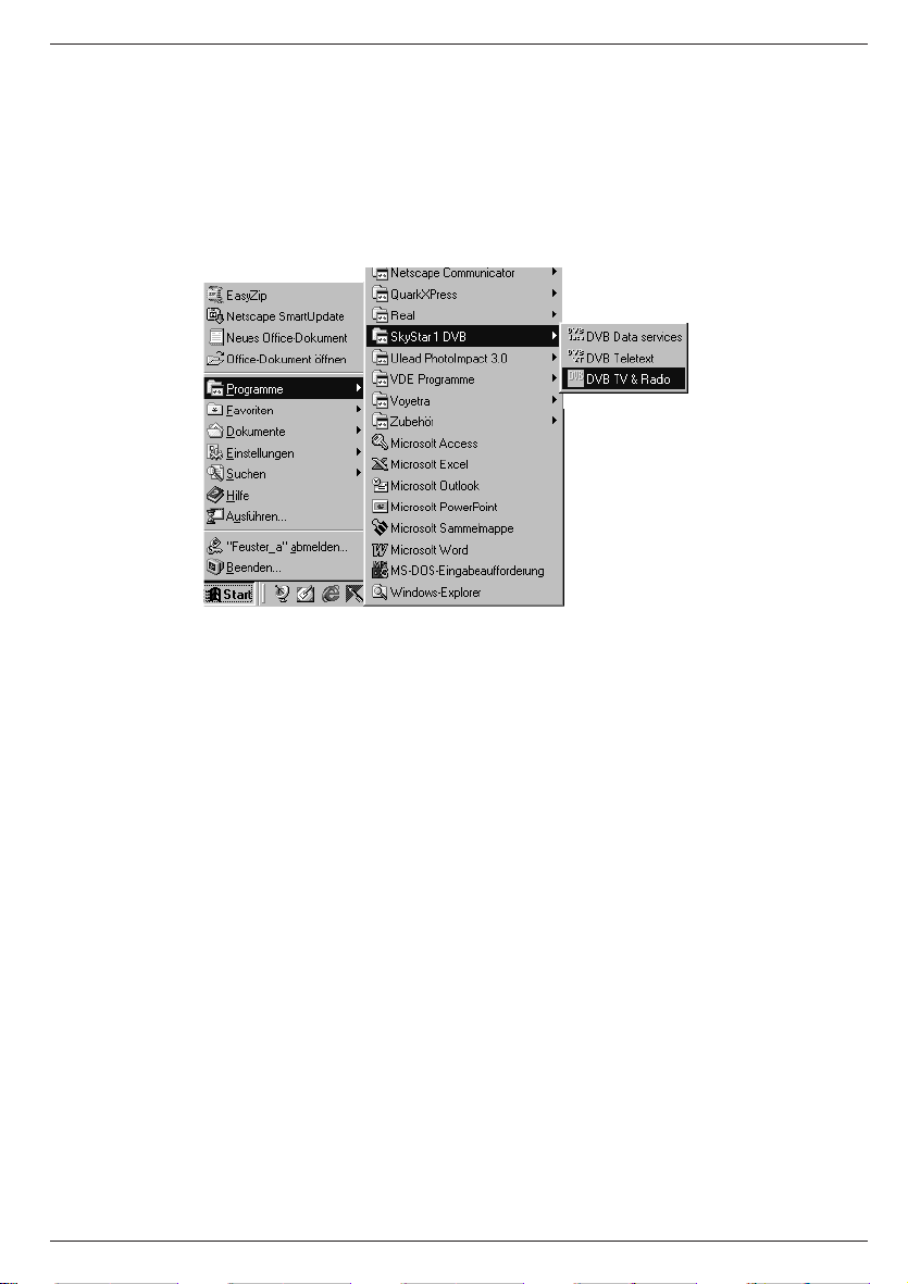
After installing the DVB PC card and the software, you can choose between several application programs. To select and start the applications, click on Start in the Windows task bar. In
the appearing window select Programs. The files can be found in the folder SkyStar1
DVB.
Following applications are available:
DVB TV & Radio
enables the reception and playback of DVB TV and radio programs.
DVB Teletext
is a simple teletext browser. DVB teletext only starts, if DVB TV & Radio is started.
DVB Network Setup Help
supports a later installation or configuration of the TechniSat SkyStar1 DVB Network driver.
DVB Data services
enables the reception of IP based DVB data services. Profiles for the reception of different
data services can be stored.
All DVB applications automatically start a further program: the TechniSat SkyStar1 DVB Server. This program controls the access to the TechniSat SkyStar1 DVB card in the background. If the TechniSat SkyStar1 DVB Server is started, you can pop-up the status bar by
double-clicking on the DVB symbol in the Windows task bar (hint: The program TechniSat
SkyStar1 DVB Server can be closed with ALT+F4.)
Before your DVB card is ready for reception you first need to adjust it to your reception
system.
To do so, please first start the application DVB TV & Radio.
7
Page 8
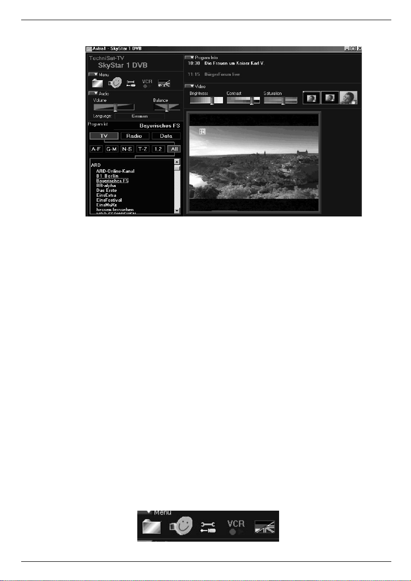
During DVB TV/Radio operation you can receive digital television and radio programs. In the
program list, sorted by provider or in alphabetical order you can change stations by mouseclick. The TV picture is scaled with the application window, furthermore, several frame
modes with hidden controls are adjustable. In this case you can change stations and control
the volume with the keyboard.
The program window consists of several control bars which can be switched on and off by
mouse-click, a field for the program list and the thickly framed TV picture. Program lists are
stored as files on the hard disk. This enables you to use different lists (e.g. separate TV and
radio lists).
Almost all controls, even those in pop-up windows are provided with so-called "tool tips".
These are small boxes with texts that are automatically shown when you move the mouse
over the control and remain there for approximately one second. Possibly, you need to click
on the main page of the application window or the relevant dialog window first to move it into
the foreground.
2.1 Switching control bars on and off
In the left upper corner of a control bar is a small button with an arrow pointing down or
right. On clicking on one of these buttons you can open or close the affiliated control bar. If
the control bar is closed, the arrow points to the right; if the control bar is open, it points
down.
The control bar Menu contains five symbols. By clicking on one of these symbols you can
start the functions listed in the following table.
1 2 3 4 5
8
Page 9
1) Open the menu Program List
2) Open the window Transponder Scan
3) Open the window LNB/Satellite Settings
4) Open the window Record/Playback
5) Open the menu for selection of operating language (German or English)
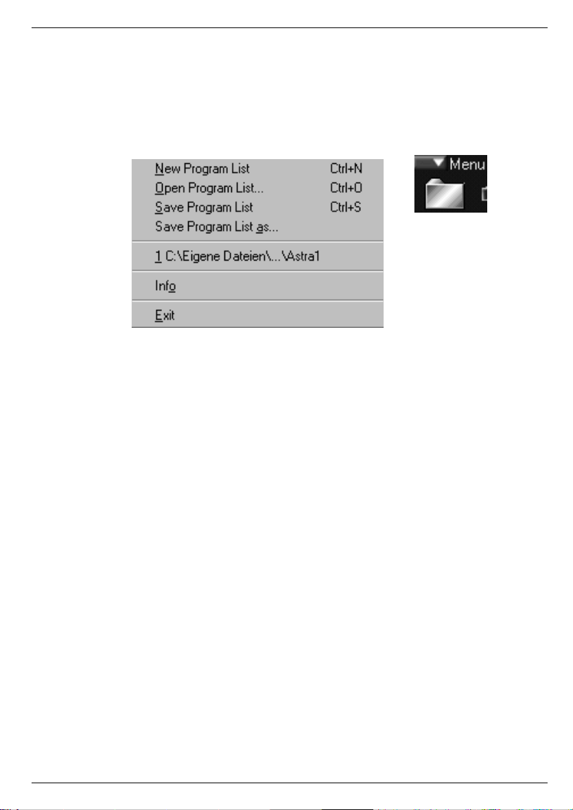
2.2 Menu Program List (tool pit 1)
The menu Program List lets you select the following commands:
New Program List
A new program list is created.
Open Program List
Opens an existing program list. For this, a dialog appears to select the file.
Save Program List
Stores the program list in a file. If the program list was not stored before, a dialog for
the file selection appears.
Save Program List as ...
Stores the program list in a file with a different filename. A dialog is opened for the
file selection.
1,2,3
Lists the files opened last. Allows opening an existing program list without opening a
panel for the file selection.
Info
Opens a window with information on copyright and version.
Exit
Closes the DVB TV & Radio application. If you have altered the program list and
have not stored it yet you are automatically asked to do this. You then have the choice to discard or to store the alterations or you can cancel the Exit function and further
work with the application.
With the next start of the DVB TV & Radio application the program list and the last selected
channel is automatically activated.
9
Page 10

3 Adjustment to your Satellite Reception System (tool pit 3)
In order for your DVB PC card to receive all channels it must be adjusted to
your satellite reception system.
To do so, please open the window LNB/Satellite Settings.
The controls of this window carry out the following functions and displays:
LNB/Satellite List
List with the symbolic names of the LNBs i.e. satellite positions. To each entry individual features are assigned. If you select an entry in the list these features are shown in the corresponding fields and can be changed.
Remove
Deletes the selected LNB from the list.
New
Generates a new LNB. You can enter the symbolic name and type.
Save
Assigns the current features to the selected LNB.
LOF (Local Oscillator Frequency)
The Transponder frequencies of the common television satellites often lie within the range of
10 GHz and higher. Since the attenuation losses of the coaxial cable during the transmission
of such high frequencies are too big, the LNB (Low Noise Block converter, sometimes also
LNC - Low Noise Converter) at the antenna converts the signal to a lower frequency range,
the so-called Sat-IF (950 to 2150 MHz). This is also the input frequency range of digital
satellite receivers and the DVB PC card.
LOF indicates the value by which the input frequency is converted. The DVB PC card requires the input of this value in order to be able to display the actual input frequencies during
the station search. The LOF is printed on the LNB. Digital compliant Universal LNBs have 2
LOFs, one for the low band (11 GHz band) and one for the high band (12 GHz band). The
switching between the two LOFs is handled with a 22 kHz signal. If you alter the LOF
values, the threshold i.e. switching frequency changes, too.
10
Page 11

LOF 1
LOF 1 (low band for Universal LNB)
LOF 2
LOF 2 (high band for Universal LNB)
LOF higher
Indicates whether the LOF lies above the input frequency range, usually with C-band LNBs.
Then the Sat-IF is LOF value minus input frequency.
From
Lowest threshold value of the input frequency range. Results from the LOF settings. If you
know that a certain satellite does not transmit DVB channels below a certain frequency, you
can increase this value accordingly. This can speed up the station search.
To
Highestt threshold value of the input frequency range. Results from the LOF settings. If you
know that a certain satellite does not transmit channels above a certain frequency, you can
decline this value accordingly. This can speed up the station search.
Switch
Indicates the frequency at which a Universal LNB should be switched from low to high band
with a 22 kHz signal.
Power
Indicates whether the LNB needs power supply. Should always be activated.
22 kHz
Indicates whether the 22 kHz signal should be sent to the LNB. With Universal LNBs that is
automatically done in relation to the chosen frequency.
DiSEqC
The DiSEqC settings (Digital Satellite Equipment Control) are important, if you connect the
DVB PC card to a satellite system which enables the reception of multiple satellites and the
combination of the individual antenna signals is handled by DiSEqC multiswitches.
None
Choose this option, if you connect the DVB PC card directly to a single satellite antenna
installed for the reception of only one satellite position.
Mini-DiSEqC
Choose this option, if the DVB PC card is connected to a switching box with "tone burst control" (also called "Mini-DiSEqC" or "Simple DiSEqC"). Then you have the possibility to choose between two satellites.
DiSEqC Levels 1.0
Choose this option if the DVB PC card is connected to a switching box or a multiswitch with
DiSEqC control. Then you can choose between four possible settings (Position/Option).
For the selected satellite position set the position to A or B and the option to A or B according to your multiswitch connection.
11
Page 12

4 Searching New Channels
This chapter describes how you can search new channels. There are two
ways: the automatic and the manual transponder scan.
4.1 Window Transponder Scan
In the window Transponder Scan you can search for new DVB channels and update the program list. With the controls of this dialog window you can execute the following functions:
Transponder
LNB/Satellite
Selection of the LNB i.e. the satellite. Select the satellite for which you would like to execute
a station search or update.
H/V
Adjust the polarization level (horizontal or vertical).
Symbol rate
Selection and input of the symbol rate. The DVB PC card needs the input of the symbol rate
to recognize the transponder(s).
Frequency
Adjustment of the transponder frequency. The Transponder frequency can be adjusted with
the slider or with the arrow keys of the keyboard.
<-? / ?->
Search the previous or following transponder based on the currently adjusted frequency. The
search is executed for the selected satellite with the adjusted polarization and symbol rate.
12
Page 13

Auto Scan
Opens a window for the automatic search throughout the whole frequency range.
Frontend Status
Signal
Indicates, whether a DVB signal is found.
Carrier
Indicates, whether a carrier signal is found.
Viterbi
Indicates, whether the Viterbi Decoder is engaged.
FSync
Indicates, whether the DVB frame synchronization was recognized.
Level
Display of the estimated signal/noise ratio in dB.
Quality
Display of the bit-error rate in four steps (better than 10-1, 10-2,10-3 or 10-4).
A DVB transponder is regarded as recognized when the display fields Signal, Carrier, Viterbi
and FSync are set.
Program List
List
Listing of the current program list. Already existing channels are displayed blue, newly recognized or updated channels appear green. Individual or multiple channels can be marked.
The channel which was marked the least is tuned in. For TV channels, the TV picture is
represented on the right side of the dialog box.
Remove
Deletes the marked channels from the program list.
Store list
Adds newly recognized channels and saves the settings of updated channels to the program
list.
TV / Radio / Data Services
Here, you lay down which type of channels should appear in the listing.
New / Updated only
Activate this control button, if only new or updated channels should be listed.
Cancel
Clicking on Cancel closes the window and lets you return to the main window. Alterations in
the program list are not saved.
OK
The OK button also closes this window. New or updated channels can be saved into the program list after confirmation in a pop-up window.
13
Page 14
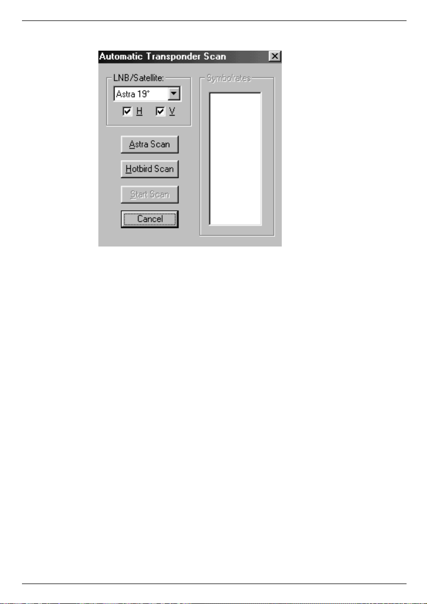
4.2 Window Automatic Transponder Scan
The window Automatic Transponder Scan automatically searches the entire frequency range
of one satellite position for DVB channels. At the moment, the automatic search for MCPC
transponders on Eutelsat Hot Bird at 13° East with 27.5 MSym/s and on the Astra satellites
at 19° East with 27.5 or 22 MSym/s is supported.
The pop-up window Automatic Transponder Scan is opened with the AutoScan button.
With the controls of this window you can execute the following functions:
LNB/Satellite
Selecting the LNB i.e. the satellite. Select the satellite on which you would like to search or
update a DVB channel.
H / V
Select the polarization level for the search (horizontal and/or vertical).
Astra Scan
Searches frequencies up to 12.5 GHz for transponders with a symbol rate of 27.5 MSym/s,
for frequencies over 12.5 GHz transponders with a symbol rate of 22 MSym/s. These is the
common configuration for the Astra satellites at 19° East at present.
Hotbird Scan
Searches all transponders with a symbol rate of 27.5 MSym/s This is the common configuration for the Eutelsat Hotbird satellite at 13° East at present.
Cancel
Closes the window.
14
Page 15

5 Operation
5.1 Control Bar Video
The control bar Video is equipped with three sliders to adjust brightness, contrast and saturation. Furthermore there are three buttons for different frame modes.
1 2 3
1) Centers the video-picture within the program window as window-filling as possible
with the side-relation of 4:3. The maximum size of the video-picture is approximately
768x572 pixels. Window-areas not covered by the video-picture are shown black.
To return to the normal operation mode, please double-click the left mouse button on
an any position in the video-picture.
2 Frame-mode with current screen-resolution. The video-picture is centered on the
screen with its maximum picture-size (approx. 768x572 pixels) while the desktop and
all other program-windows are covered with a black background.
To return to the normal operation mode, please double-click the left mouse button on
an any position in the video-picture or via a context-menu opened with the right
mouse button.
3 Frame-mode with screen-resolution of 800x600 pixels. The video-picture is centered
on the screen with its maximum picture-size (approx. 768x572 pixels) while the desktop and all other program-windows are shown with a black background.
Tip: Even in this mode a narrow black frame remains. But, if you don't use the 800x600-
mode of Windows otherwise, with this resolution you can zoom the picture until the
black frame disappears and the TV picture covers the complete screen.
To return to the normal operation mode, please double-click the left mouse button at
any position in the video-picture or via a context-menu opened with the right mouse
button.
TV picture
In accordance with the window size the TV-picture is represented as big as possible with the
side relation of 4:3 (max. approx. 768x572 pixels). During normal operating mode you can
change to the frame-mode by double-clicking the left mouse button in the TV-picture.
Double-clicking the right mouse button you will return to the last used frame-mode (with current screen-resolution i.e. with 800x600 pixels).
During frame-mode you can change channels with the arrow keys on your keyboard (arrow
up or down) or alter the volume (arrow left or right).
Return from frame-mode to normal operating mode by double-clicking of the left mouse button on on any position in the video-picture.
15
Page 16

5.2 Control Bar Audio
The control bar Audio contains two sliders for the adjustment of the volume and balance as
well as an input field to display the text of the audio channel of the tuned-in station. If the
station does not transmit any text information ~no info~ or the Audio PID is displayed.
If several audio channels are transmitted via the tuned-in frequency, use the arrow keys to
switch between the audio channels.
5.3 Control Bar Program lnfo
The control bar Program Info shows beginning time, title and subtitle of the current and the
following program. These information can only be displayed if they are transmitted.
16
Page 17

5.4 Control Panel Program List
The control panel Program List contains a listing of the individual channels as well as two
rows of buttons to set the criteria for the listing. A channel is tuned-in by clicking on a channel's name.
With the buttons TV, Radio and Data you can choose what kind of channels should be
displayed.
With the buttons A-F, G-M etc. you reduce the channel selection to the corresponding
beginning letters.
If the All button is activated, all channels are listed, sorted according to suppliers.
The name of the tuned-in channels is shown in the upper right corner of control panel Program List.
17
Page 18

5.5 DVB Teletext Applikation
The application DVB Teletext is a simple teletext browser. DVB Teletext can only be started
parallel to the application DVB TV & Radio. If you tune-in a TV channel with teletext in the
DVB TV & Radio application, DVB Teletext stores all incoming teletext pages.
The application is operated via the buttons arranged at the lower edge of the window.
Copy
Copies the current page into the buffer store.
Print
Prints the current page.
Hold
Prevents updating of the page if a new version is received.
???
Release button for hidden text.
100
Goes to page 100 (start page)
Save
Stores the current page as HTML document.
Forward
Forward scroll in the list of already visited pages.
Back
Back scroll in the list of already visited pages.
Page, «,»
Input of a certain page number, one page forward or back
Subpage, «,»
Selection of a subpage, scroll through the subpages.
Close
Ends the DVB teletext application.
Furthermore, the numbers of the arriving pages as well as the time information encoded in
the teletext are shown.
18
Page 19
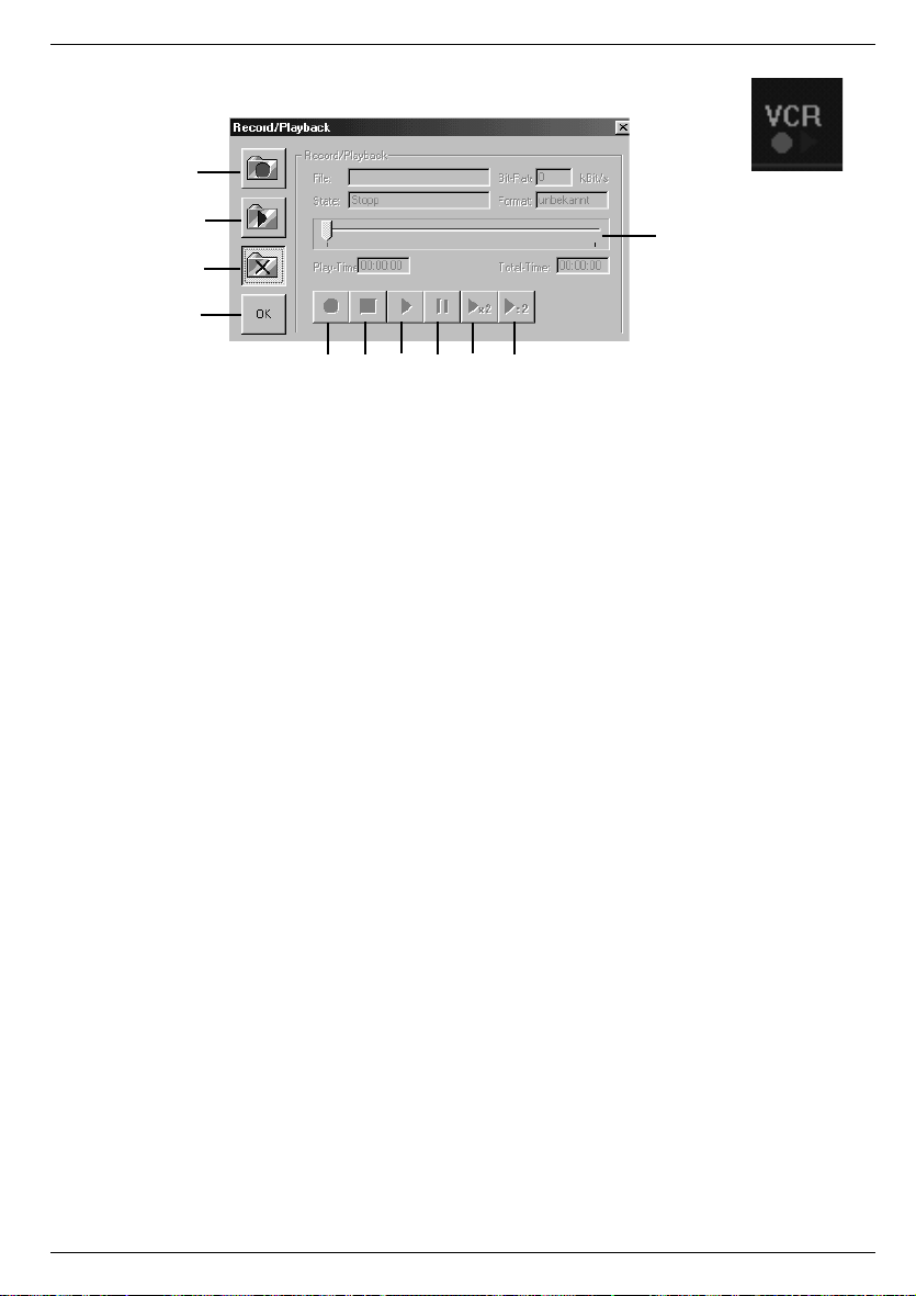
5.6 Record/Playback
1
2
3
4
5 6 7 8 9 10
The window Record/Playback enables the recording of a tuned-in TV or radio channel onto
your hard disk. You can choose whether you would like to record only the video stream or
audio stream or both combined. This window lets you also playback previously recorded
video/audio streams.
With the controls of this window you can execute the following functions:
File
Indicates the path of the opened file.
State
Shows the current status (record / playback / stop...).
Bit-Rate
Indicates the speed of the current recording or playback.
Format
Indicates the format of the opened file.
Play-Time
Indicates the playing time during playback mode with reference to the beginning of the file.
During record mode the current recording time is displayed.
Total-Time
Indicates the total running time of the file during playback mode. During record mode the
current recording time is displayed.
11
1) Selects and opens a file for recording. Execute this command before starting to
record the currently tuned-in program. You are asked to select or enter the file name
and the recording format.
2) Selects and opens a file for playback. You are asked to select or enter the file name.
3) Closes record/playback file.
4) Closes window.
5) Record button. Starts the recording. This command can only be executed if a file for
recording is opened.
6) STOP key. Stops a current recording or playback.
19
Page 20

7) Playback button. Starts the playback mode. This command can only be executed if a
file for playback is opened.
8) Pause key. Stops the playback mode and displays a still frame of the current video
picture. If this button is pressed several times, you can move through the video image
by image.
9) Fast playback (only for video or audio MP2). The file is shown with double speed.
10) Slow playback (only for video or Audio MP2). The file is shown with half speed.
11) Indicates the current position during playback mode with reference to the total file
length. By moving the slider you can change the current position by hand.
Hint
The video and audio streams are stored in the MPEG-2 format on the hard disk. Please consider that fast and large hard disks are needed for data rates of up to several MBit/s. To
record a 4 MBit/s video stream for one minute you will need about 30 Mbytes, and for one
hour already 1.8 Gbytes.
6 DVB Data Services
With the TechniSat SkyStar1 DVB card you can use all IP-based DVB data services. This
includes for example High Speed Internet, Web/News Broadcast services (Web Casting),
Multicast Streaming services or File Transfer services.
If the PC card is used for DVB Data services it acts just like any regular network card. This
enables the reception of any IP-based DVB data services. Furthermore, this way the smooth
integration into the Windows network architecture and the compatibility with Internet applications is guarantied.
Since the DVB PC card does not retrieve its data from a network but via DVB data broadcasting, some additional settings are necessary. The data application allows the administration
of as many services as you like and enables a simple adjustment of all necessary parameters.
Hint: The program TechniSat SkyStar1 DVB Servers can be closed with ALT+F4.
20
Page 21

Almost all controls, even those in pop-up windows are provided with so-called "tool tips".
These are small boxes with texts that are automatically shown when you move the mouse
over a control button and remain there for approximately one second. Possibly, you need to
click on the main page of the application window or the relevant dialog window first to move
it into the foreground.
For the DVB PC card to work as a network card, certain front-end adjustments need to be
done and so-called filters need to be configured. Front-end defines the input stage of the
DVB PC card consisting of tuner, demodulator, LNB power supply and control and DiSEqC
signal generator. All settings that are necessary for the reception of a DVB signals are entered in the index cards Status/Tuner and DiSEqC/LNB.
Filters are used to extract information relevant for the DVB data service from the DVB signal.
Depending on the DVB data service one or more filters need to be configured on the index
card Filter. The index card Statistics shows the information density (bit rate) of the selected filters.
Services
In context with the SkyStar1 data application a service means a set with all parameters
necessary for the reception of a DVB sat data service.
With the selection of a service all adjustments are done in a way that the corresponding
DVB data service can be used. The parameters belonging to a service can be changed on
the index cards of the SkyStar1 Data application and activated and stored on pressing the
button Apply. The parameters needed for the use of a DVB data service (frequency, symbol rate, polarization, PID, IP or MAC address) are given to you by the supplier of the service.
To fade out the application window press the button Hide. By double clicking on in the
Windows task bar the application window reappears. To close the application press on Exit.
Add Data Service
The window Add Data Service opens on pressing the button New. After that you need to
enter a definite (not jet used) name for the new data service in the entry field Name of Data
Service. In order to not have to enter all parameters for each new service again a list allows
to adopt the settings of already existing services. These can be modified then. On pressing
OK the service is installed.
Cancel discards the inputs.
21
Page 22

6.1 Select a Service
The selection of a service is simply done by opening the Service Selection and choosing an
entry. On starting the program the finally chosen entries are activated again. The three buttons New, Change and Remove are used to manage the services.
Change Service
The window Change Data Service opens on pressing the button Change. Now, a different
name for the service can be entered. OK accepts the change of the service's name and
Cancel discards the input.
The button Remove deletes the current service from the list of the available services and
all affiliated parameters.
6.2 Index Card State / Tuner
The index card State/Tuner represents different reception parameters. Furthermore, it allows
to adjust tuner and demodulator settings, e.g. frequency and symbol rate. Alterations only
become effective after pressing Apply.
Tuner State
Synchronization
Indicates whether a DVB signal is recognized.
22
Page 23

Signal Quality
Indicates the quality of the received signal. A value of 100% represents an error-free reception (bit error rate better than 10 E-4).
Signal Level
The level of the received signal in percent. With the help of this value the antenna can optimally be aligned.
Acoustic Signalization
The acoustic signalization helps during the alignment of the antenna. The signal strength
can be heard via your sound card.
Tuner Settings
Frequency
Entering the transponder frequency.
You can directly enter the transponder frequency or adjust it step-by-step with the arrow
keys.
Symbol Rate
Selecting or entering the symbol rate.
The DVB PC card requires the input of the symbol rate to recognize the corresponding
transponder.
H / V
Only with DVB-s cards (satellite). Please enter the polarization level (horizontal or vertical).
QAM
Only with DVB-c cards (cable). Indicates the modulation type of the cable network. If necessary, the cable network provider will give you the modulation type.
23
Page 24

6.3 Index Card DiSEqC / LNB
With the settings on the index card DiSEqC/LNB, the DVB PC card is adjusted to your satellite system. Alterations only become effective after accepting with Apply.
DiSEqC Settings
The DiSEqC settings (Digital Satellite Equipment Control) are of importance, if you connect
the TT-DVB sat PCl card to a satellite system which enables the reception of several orbital
positions and the combination of the individual antenna signals is handled by DiSEqC switches or DiSEqC multiswitches.
None
Choose this option, if you connect the DVB PC card directly to a single satellite antenna
installed for the reception of only one satellite position.
Simple (tone burst)
Choose this option, if the DVB PC card is connected to a switching box with "tone burst control" (also called "Mini-DiSEqC" or "Simple DiSEqC"). You then have the possibility to choose
between two satellite signals (orbital positions).
Level 1.0
Choose this option, if the DVB PC card is connected to a device with DiSEqC control. You
then can choose between four possible settings (Position/Option). For the correct settings
consult the instructions of your DiSEqC multiswitch.
LNB Settings
The transponder frequencies of the common television satellites often lie within the range of
10 GHz and higher. Since the attenuation losses in the coaxial cable during the transmission
of such high frequencies are too big, the signal is converted right at the antenna - inside the
LNB (Low Noise Block converter, sometimes also LNC - Low Noise Converter) - into a lower
frequency range, the so-called Sat-IF (950 to 2150 MHz). This is also the input frequency
range of digital satellite receivers and the DVB PC card.
24
Page 25

LOF 1
LOF 1 is the Local Oscillator Frequency for the low band.
LOF indicates the value by which the input frequency is converted. The TT-DVB sat PCl
card requires the input of this value in order to be able to process the actual input frequencies. The LOF is printed on the LNB. Digital compliant Universal LNBs have 2 LOFs, one for
the low band (also 11 GHz band) and one for the high band (also 12 GHz band). The switching between the two LOFs is handled with a 22 kHz signal.
LOF 2
LOF 2 is the Local Oscillator Frequency for the high band.
See also LOF 1.
Switch
Indicates the frequency at which a Universal LNB should be switched from low to high band
with a 22 kHz signal.
LNB power supply
Indicates, whether the LNB should be provided with power. Should always be activated.
6.4 Index Card Filter
The index card Filter is used for the configuration of the filter and for display of the filter
parameters. The filters are adjusted with the buttons Add, Edit and Delete. The alteration of
the def. Multicast PID only becomes effective after accepting with Apply.
PID (Packet-Identifier)
The PID selects one single stream of the multitude of packet streams which make up the
DVB signal. The service provider lets you know which PID is used for the transmission of the
its DVB data service.
25
Page 26

def. Mdef. Multicast PID
If a supplier transmits all multicast DVB data services with the same PID, it is useful to fill in
the PID. The SkyStar1 data application is then able to automatically set further multicast filters when requested. Otherwise, the entry field should remain empty.
Set
Indicates, whether a filter is set (is used). The following abbreviations are used: UC - Unicast
Filter; BC - Broadcast Filter; MC - Multicast Filter. The filter can only be set by the SkyStar1
data application, if the application is allowed (column use) and a valid PID (column PID) is
entered.
MAC (Media Access Control)
Mac address: The Mac address further differentiates the package stream chosen with the
PID. Because of that, only packages with the right address reach the Windows network. For
multicast DVB data-services the Mac address can be calculated from the IP address. In this
case, the input of the IP address is sufficient.
IP (Internet Protocol)
The IP address is not important for the filtering process, however, it makes the assignment
of filters to client applications and the address input for multicast filters.
Length
Number of bytes of the MAC address integrated in the filtering process (usually 6, with 0 the
filter is only for PID.
use
Indicates, whether a filter should be used.
Adding a filter
On pressing the button Add or double-clicking on a free spot in the filter list the pop-up
window Filter Settings opens. The input fields already contain the pre-set values for a
new filter. Adjust the diameters as needed. Pressing OK adds the new filter to the filter list.
Cancel deletes the inputs.
26
Page 27

Delete removes the selected filter from the list of available filters and all corresponding
parameters.
Change Filter Parameter
The window Filter Settings can be opened by pressing the button Edit or by double-clicking
on the PID to be changed. The input-fields contain the settings of the filter. Alter the desired
parameters. On pressing OK the altered settings are entered in the filter list.
Cancel deletes the alterations.
6.5 Index Card Filter Statistics
The index card Statistics shows the total data rate of the filters set in bit/s.
27
Page 28

7 Technical Data
7 Technical Data
7 Technical Data
7 Technical Data
Tuner
Tuner
Tuner
Tuner
Satellite tuner with integrated QPSK modulator (on-board) C and KU band compliant
Satellite tuner with integrated QPSK modulator (on-board) C and KU band compliant
Satellite tuner with integrated QPSK modulator (on-board) C and KU band compliant
Satellite tuner with integrated QPSK modulator (on-board) C and KU band compliant
Input frequency:
Input frequency:
Input frequency:
Input frequency:
950 to 2150 MHz
950 to 2150 MHz
950 to 2150 MHz
950 to 2150 MHz
Input levels:
Input levels:
Input levels:
Input levels:
-65 to -25 dBm
-65 to -25 dBm
-65 to -25 dBm
-65 to -25 dBm
LNB voltage supply:
LNB voltage supply:
LNB voltage supply:
LNB voltage supply:
off/on, 14V / 18V at max. 400 mA
off/on, 14V / 18V at max. 400 mA
off/on, 14V / 18V at max. 400 mA
off/on, 14V / 18V at max. 400 mA
LNB control:
LNB control:
LNB control:
LNB control:
22 kHz and DiSEqC 1.0
22 kHz and DiSEqC 1.0
22 kHz and DiSEqC 1.0
22 kHz and DiSEqC 1.0
Symbol R a te:
Symbol R a te:
Symbol R a te:
Symbol R a te:
from 1 to 45 MSPS
from 1 to 45 MSPS
from 1 to 45 MSPS
from 1 to 45 MSPS
SCPC and MCPC compliant
SCPC and MCPC compliant
SCPC and MCPC compliant
SCPC and MCPC compliant
High performance one-chip backend solution
High performance one-chip backend solution
High performance one-chip backend solution
High performance one-chip backend solution
High performance multimedia PCI bridge (PCI reference 2.1) for:
High performance multimedia PCI bridge (PCI reference 2.1) for:
High performance multimedia PCI bridge (PCI reference 2.1) for:
High performance multimedia PCI bridge (PCI reference 2.1) for:
Video Overlay Display via graphic card
Video Overlay Display via graphic card
Video Overlay Display via graphic card
Video Overlay Display via graphic card
Download of DVB program information (SDT, PMT, NIT, PAT,...)
Download of DVB program information (SDT, PMT, NIT, PAT,...)
Download of DVB program information (SDT, PMT, NIT, PAT,...)
Download of DVB program information (SDT, PMT, NIT, PAT,...)
Download of MPEG-2 audio and video data (recording function)
Download of MPEG-2 audio and video data (recording function)
Download of MPEG-2 audio and video data (recording function)
Download of MPEG-2 audio and video data (recording function)
Replay of MPEG-2 audio and video data
Replay of MPEG-2 audio and video data
Replay of MPEG-2 audio and video data
Replay of MPEG-2 audio and video data
Download of different DVB data services:
Download of different DVB data services:
Download of different DVB data services:
Download of different DVB data services:
TS packages for DVB data piping
TS packages for DVB data piping
TS packages for DVB data piping
TS packages for DVB data piping
PES packages for DVB data streaming
PES packages for DVB data streaming
PES packages for DVB data streaming
PES packages for DVB data streaming
MPEG-2 sections for DVB multi protocol
MPEG-2 sections for DVB multi protocol
MPEG-2 sections for DVB multi protocol
MPEG-2 sections for DVB multi protocol
DVB data Carousels and DVB Object Carousels
DVB data Carousels and DVB Object Carousels
DVB data Carousels and DVB Object Carousels
DVB data Carousels and DVB Object Carousels
This DVB-PC card is CE approved and fulfils all necessary EC regulations!
This DVB-PC card is CE approved and fulfils all necessary EC regulations!
This DVB-PC card is CE approved and fulfils all necessary EC regulations!
This DVB-PC card is CE approved and fulfils all necessary EC regulations!
Errors and misprints excepted. Dated 11/99
Errors and misprints excepted. Dated 11/99
Errors and misprints excepted. Dated 11/99
Errors and misprints excepted. Dated 11/99
TechniSat and SkyStar1 are registered trademarks of
TechniSat and SkyStar1 are registered trademarks of
TechniSat and SkyStar1 are registered trademarks of
TechniSat and SkyStar1 are registered trademarks of
TechniSat TV GmbH
TechniSat TV GmbH
TechniSat TV GmbH
TechniSat TV GmbH
Postfach 560 - 54541 Daun
Postfach 560 - 54541 Daun
Postfach 560 - 54541 Daun
Postfach 560 - 54541 Daun
www.technisat.de
www.technisat.de
www.technisat.de
www.technisat.de
28
28
28
28
407_00
 Loading...