

Page 1
5700126300
Page 2
SAFETY INSTRUCTIONS
CAUTION:
• Read all of these instructions.
• Save these instmctions for later use.
• Follow all warnings and instructions marked on the
audio equipment.
1. Read Instructions—All thesafetyandoperatinginstructions
should be read before the appliance is operated.
2. Retain Instructions — The safety and operating instructions
should be retained for future reference.
3. Heed Warnings — All warnings on the appliance and in the
operating instructions should be adhered to.
4. Follow IfRtructions — All operating and use instructions
should be followed.
5. Water and Moisture — The appliance should not be used
near water - for example, near a bathtub, washbowl, kitchen
sink, laundry tub, in a wet basement, or near a swimming
pool, etc.
6. Carts and Stands — The appliance should be used only with
a cart or stand that is recommended by the manufacturer.
6A. An appliance and cart combination should be moved with
care. Quick stops, excessive force, and uneven surfaces may
cause the appliance and cart combination to overturn.
13. Cleaning — The appliance should be cleaned only as recommended by the manufacturer.
14. Power Lines — An outdoor antenna should be located away
from power lines.
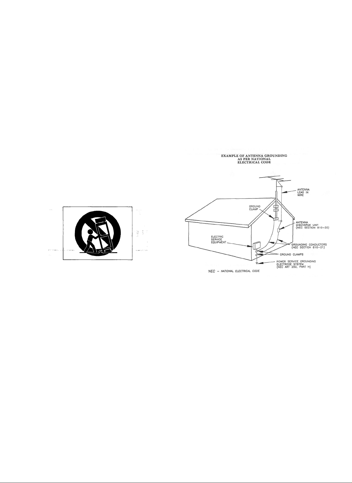
15. Outdoor Antenna Grounding — If an outside antenna is
connected to the receiver, be sure the antenna system is
grounded so as to provide some protection against voltage
surges and built up static charges. Section 810 of the
National Electrical Code, ANSI/NFPA No. 70 - 1984, provides information with respect to proper grounding of the
mast and supporting structure, grounding of the lead-in
wire to an antenna discharge unit, size of grounding conductors, location of antenna-discharge unit, connection to
grounding electrodes, and requirements for the grounding
electrode. See Figure below. ,
Wall or Ceiling Mounting — The appliance should be mount-
ed to a wall or ceiling only as recommended by the manufacturer.
Ventilation - The appliance should be situated so that its
8.
location or position does not interfere with its proper venti-
lation. For example, the appliance should not be situated
on a bed, sofa, rug, or similar surface that may block the
ventilation openings; or, placed in a built-in installation,
such as a bookcase or cabinet that may impede the flow of
air through the ventilation openings.
Heat — The appliance should be situated away from heat
9.
sources such as radiators, heat registers, stoves, or other
appliances (including amplifiers) that produce heat.
10. Power Sources — The appliance should be connected to a
power supply only of the type described in the operating in-
structions or as marked on the appliance.
Grounding or Polarization — The precautions that should
11
be taken so that the grounding or polarization means of an
appliance is not defeated.
Power-Cord Protection — Power-supply cords should be
12
routed so that they are not likely to be walked on or pinch-
ed by items placed upon or against them, paying particular
attention to cords at plugs, convenience receptacles, and
the point where they exit from the appliance.
16. Nonuse Periods — The power cord of the appliance should
be unplugged from the outlet when left unused for a long
period of time.
17. Object and Liquid Entry - Care should be taken so that
objects do not fall and liquids are not spilled into the enclosure through openings.
18. Damage Requiring Service - The appliance should be ser-
viced by qualified service personnel when:
A. The power-supply cord or the plug has been damaged; or
B. Objects have fallen, or liquid has been spilled into the
appliance; or
C. The appliance has been exposed to rain; or
D. The appliance does not appear to operate normally or
exhibits a marked change in performance; or
E. The appliance has been dropped, or the enclosure dam-
aged.
19. Servicing — The user should not attempt to service the
appliance beyond that described in the operating instructions. All other servicing should be referred to qualified
service personnel.
-2
Page 3

Page 4

4-
Page 5

Precautions
Features and Controls (Fig. i)
Environment
Avoid using the deck in the following circumstances:
• High temperature (such as heater, direct
sunlight).
• Extremely low temperature. ^ ^'^ '
• Excessive humidity. ''"•
• Dusty atmosphere.
• Where power line voltage fluctuation is
severe (the use of a voltage regulator may
be advisable).
• Be aware also that placing other units or
any objects on the deck can leave marks
depending on their weight.
Cassette Tape (Fig. 5)
Tape Selection:
For the automatic tape select function to
work properly, metal and chrome (cobalt)
formula tapes must have tape identification
holes.
C-120 cassette tapes:
120-minute tapes are very thin, they tend
to stretch and their magnetic layer is thin;
they also tend to introduce wow & flutter.
For these reasons, special attention is
required when using them. If the pinch
roller or capstan is dirty, tape might become
wrapped around it and this could cause
serious trouble. For this reason, it is re-
commended that you do not use C-120
tapes.
Tape Handling: <
Do not store tape in the following places:
• On top of heaters, in direct sunlight or in
any other high-temperature areas.
• Near speakers, on TV sets or amplifiers or
near any strong magnetic fields.
• High-humidity areasordirty, dusty areas.
Avoid dropping or subjecting the cassettes
to excessive shock.
Voltage Conversion (For general export
models) (Fig. 6)
If it is necessary to change the voltage
requirements of the deck to match your
area, use the following procedure:
1. DISCONNECT POWER LINE CORD.
2. Using a screwdriver, turn the selector
until the desired voltage marking appears.
f :• ;J, i
IMPORTANT (for U.K. Customers)
The wires in this mains lead are coloured
in accordance with the following code:
BLUE:
BROWN:
As the colours of the wires in the mains
lead of this apparatus may not correspond with the coloured markings identifying the terminals in your plug, proceed as follows:
The wire which is coloured SLUE must
be connected to the terminal which is
marked with the letter N or coloured
BLACK. The wire which is coloured
BROWN must be connected to the
terminal which is marked with the letter
L or coloured RED.
In the U.K. this unit is sold without an
AC plug.
THE APPLIANCE CONFORMS WITH
EEC DIRECTIVE 87/308/EEC REGARDING INTERFERENCE SUP-
PRESSION
^ Dolby noise reduction and HX Pro head-
room extension manufactured under
license from Dolby Laboratories Licensing Corporation. HX Pro originated by
Bang & Olufsen. "DOLBY", the doubieD symbol DO and "HX PRO" are trademarks of Dolby Laboratories Licensing
Corporation. «ii|i., -s,
Connections (Fig. 4)
• Turn off power for all equipment before
making connections.
• Read instructions for each component
you intend to use with the deck.
NEUTRAL
LIVE
Front Panel/Remote Control Unit
OPOWER Switch
Press to switch the deck on. The display
window will be illuminated. Press again to
turn the deck off.
Note: Be sure to wait more than 2 seconds
after the power has been switched
off before switching the power on
again.
0 '*^ (Rewind) Button/ •• (Fast-
Forward) Button
When these buttons are pressed, the tape is
rewound or fast-forwarded.
©REMOTE SENSOR (Remote Con-
trol Infrared Signal Receptor)
This receives signals from the provided
RC-393 infrared remote control unit.
OSTOP Button
Press to stop the tape travel and release
any other mode.
© • (Play) Button
Pressing this button starts normal-speed
playback.
0 II (Pause) Button
Press to temporarily stop tape travel during
recording or playback. In the pause mode,
the PAUSE indicator in the display lights.
Press the • button or ii button again
to restart the tape (the indicator goes out).
ORECORD Button
Press the RECORD button to set the deck
to the record-pause mode. The REC and
PAUSE indicators will light. To start record-
ing, press the • button or ii button.
To enter the record mode using the remote
control, press the two RECORD buttons
simultaneously.
©REC MUTE Button '"••':^-
Press this button during recording to leave
a blank section between tunes (approx. 4 seconds). The deck will enter the recordpause mode. Press the • button or "
button to start recording again. (See page 7.)
©CLEAR Button
Pressing the CLEAR button resets the multicounter to "0000".
©MODE Button =^
When this button is pressed, the display
alternates between the conventional tape
counter and the TRT (tape-run-time)
counter.
<DRTZ (Return to Zero) Button
If this button is pressed, the tape is fastforwarded or rewound until a tape counter
reading of "0000" is reached, then the
deck stops. (See page 8.)
Page 6

<D Cassette Holder
Load the cassette here.
<DAUT0 MONITOR Button
This button allows you to select which
signal Is to be monitored with its level
displayed on the meter. When power is
applied to the deck, the monitor mode is
set to TAPE, showing that the signal recorded
on the tape is monitored with its level
displayed by the meter. When the deck
enters the record-pause mode, the monitor
mode is automatically switched to SOURCE,
showing the signal input to the deck (from
the LINE IN jacks on the rear panel) is
monitored with its level displayed. And
when the record-pause mode is released,
it is automatically changed to TAPE.
To manually change the monitor mode,
press this button.
<E>MPX FILTER Switch
Press this switch when making a Dolby NR
recording of an FM broadcast; the indicator
lights. It eliminates the pilot tone (19 kHz)
and sub carrier tone (38 kHz) of the FM
broadcast which could affect operation of
the Dolby noise reduction system. To release this function, press the MPX FILTER
switch again.
® DOLBY NR Switch
OFF; Set to this position when you do not
want to use any noise reduction
system.
••B: Set to this position when making a
recording using the Dolby B noise
reduction system, or playing back
tapes recorded with Dolby B NR.
•• C:Set to this position when making a
recording using the Dolby C noise
reduction system, or playing back
tapes recorded with Dolby CNR.
©TIMER Switch
PLAY: For timer playback
OFF: Set to this position when not using
a timer.
REG: For timer recording
(See page 8.)
® EJECT Button
Press in the stop mode to open the cassette
holder. Do not press this button when the
deck is in the recording or playback mode.
(D BIAS FINE Tuning Control
This control allows fine bias level setting
when recording. The center "click" position
provides a standard amount of bias current
depending on the type of tape.
Turning the control toward "+" increases
the amount of bias and thus decreases high
frequency response.
Turning the control toward "-" decreases the
amount of bias and thus increases high
frequency response.
Keep this control in the center position
when the function is not being used.
©BALANCE Control
Adjust the balance of the left and right
chanels of the input signals to be recorded
on tape.
®REC LEVEL Control
When recording, turn the REC LEVEL
control clockwise to fade the input sound
in or turn it counterclockwise to fade the
sound out, for smooth tune-to-tune transitions.
^PHONES LEVEL Control
Adjust the level of the signals output from
the PHONES jack. This knob does not
affect the level of the signals output from
the OUTPUT jacks on the rear panel or the
level indicated by the PEAK LEVEL
METER.
©PHONES Jack
Connect 8 ohms stereo headphones to this
jack for private listening or monitoring.
©DISPLAY Button
Press this button to switch off the display.
Press it again to switch it on.
Display JVin^pj^,,
® Multi-Counter
Tape Counter Mode
In this mode, the counter functions as a
conventional tape counter, counting up
when the tape is moving forward and down
when the tape is being rewound. The dis-
play can be cleared by pressing the CLEAR
button, which resets the counter index to
"0000".
TRT (Tape-RunTime) Counter Mode
In this mode, tape travel is measured in
minutes and seconds up to a maximum of
99M59S (99 minutes 59 seconds). Since this
counter only functions in the play and record modes, it will be interrupted when the
tape is fast-forwarded or rewound (and, of
course, in the stop mode); counting up will
be resumed when playback or recording
restarts. The display can be cleared by
pressing the CLEAR button which resets the
counter index to "OOMOOS".
©Transport Mode Indicators
REC: Lights when the deck is in the re-
cord and record-standby modes, and
flashes during record-muting.
PLAY: Lights when the deck is in the play-
back and record modes.
PAUSE: Lights when the deck is standing
by for playback or recording.
©PEAK LEVEL METER
This meter shows the peak level of the input
or playback signal. In the record mode,
the meter indicates the level of the source
signals which have been adjusted with the
REC LEVEL and BALANCE controls.
During playback, the meter indicates the
level of signals recorded on the tape.
©Tape Type Indicator
The deck automatically detects the type of
tape which has been loaded, and these
indicators (NORMAL, CrO, and METAL)
indicate the type of tape being used.
©DOLBY NR E E Indicator
Lights when the DOLBY NR switch is set
to the •• B or DD C position. = J
© DD HX PRO Indicator
Lights when the deck enters the record
mode, showing that the built-in Dolby HX
Pro circuit has been activated. For details,
refer to page 9.
• i'.- ; ^"•"'" ;^--; 'w
©MPX FILTER Indicator
Lights when the MPX FILTER switch is
pressed in ( n ).
©Auto Monitor Indicators
TAPE: Lights when the tape signal is
selected either in playback or record.
SOURCE: Lights when the source signal is
selected.
The Auto Monitor indicator changes auto-
matically to the monitor mode so that the
SOURCE indicator lights when the deck
enters the record-pause mode. When record-
ing starts, the SOURCE indicator automatically goes out and the TAPE indicator
lights.
•?» Panel'
©LINE IN Terminals
Connect the amplifier's REC OUT jacks to
these jacks.
©OUTPUT Terminals
Connect the amplifier's TAPE PLAY or
LINE IN jacks to these jacks.
©Voltage Selector (General export
models only)
See "Voltage Conversion" on page 5.
© Power Supply Cord
Insert into an AC wall outlet, etc. The
voltage required by this unit is shown on
the rear panel.
-6
Page 7

Operations
Playback and Recording
Stereo Playback
1. SettheTIMER switch to OFF.
2. Press the POWER switch to ON.
3. Load a pre-recorded cassette.
4. Select the NR system with the DOLBY
NR switch.
5. Press the • button to start playback.
6. Adjust the volume with the amplifier's
control.
Stereo Recording
1. Set the TIMER switch to OFF.
2. Press the POWER switch to ON.
3. Load a recordable cassette.
4. Select the required NR system with the
DOLBY NR switch.
5. Press the MPX FILTER switch to IN
when making a Dolby NR recording of
an FM broadcast.
6. Press the RECORD button (both the
REC and PAUSE indicators light). This
enables you to adjust the recording level
without actually recording on the tape.
7. Adjust the REC LEVEL and BALANCE
controls so that the loudest peak briefly
reaches the meter reference reading
for the type of tape used for both chan-
nels.
8. Adjust the BIAS FINE tuning control
described in "Using the BIAS FINE
Tuning Control".
9. Press the • button or ii button to
start recording. The REC and PLAY
indicators light.
The Auto Monitor indicator is auto-
matically changed to TAPE and the
signal can be directly monitored im-
mediately after it is recorded. To compare the recorded sound with the
original source, press the AUTO
MONITOR button to switch the signal
being monitored between TAPE and
SOURCE.
Notes:
• To stop recording, press the STOP button.
• To momentarily stop recording, press the
II button. To resume recording, press
the •• button or ii button.
Note:
Recording prerecorded tapes, records, or
other published or broadcast material
may infringe copyright laws. Check
these laws before recording.
Setting the Recording Level
Setting the recording level correctly is essential if you want to make top-quality
recordings. If the level is too low, the
recording will be noisy. If the level is set
too high, the recording will be distorted.
Generally speaking, the recording level
should be set so that the loudest peak to be
recorded makes the meters briefty indicate
the meter reference reading for the type of
tape used. If the meters peak over the
reference reading, decrease the recording
level by turning the REC LEVEL control
counterclockwise. However, some program
material or different tape formulations may
require higher or lower recording levels.
With a little time and practice you will be
able to select the critical recording level
that gives you the best hi-fi recordings. The
optimum setting of the recording level will
differ according to the type and condition
of the tape, as well as the type of music
you are recording.
Using the BIAS FINE Tuning Control
The center position provides the standard
amount of bias current. Turning the control
toward "+" increases the amount of bias
current; a slight decrease in high-frequency
response will be obtained. Turning it toward
"-" decreases the amount of bias current;
a noticeable increase in high-frequency
response will be obtained.
1. Set the deck in the record mode and
begin recording by using a disc or a
prerecorded tape the sound quality of
which you are familiar with.
2. Set the AUTO MONITOR button to
TAPE to monitor the reproduced sound.
If the high frequency sound seems
greater than the original, turn the BIAS
FINE tuning control toward "+" to obtain the best possible sound. On the
other hand, if the high frequency sound
seems low, turn the control toward "-"
until the appropriate bias current is obtained. -^ • '
3. As a final check, alternately set the
AUTO MONITOR to SOURCE or TAPE
to confirm the correct setting of the
BIAS FINE tuning control by comparing
the recorded sound with the original.
Erasing
A previously recorded tape will be automatically erased when you make a new
recording on it. Alternatively it can be
erased by "recording" on it with the REC
LEVEL control set to "°°".
Record Muting Operation
The ability to leave blank unrecorded
(erased) portions on a tape during recording
is a real advantage in many recording
situations. For instance, you may want to
eliminate undesired portions of an FM
broadcast that you are recording, such as
commercials, station breaks or announcements. You may want to record a complete
program with controlled spacing between
each song. Such blank portions on a tape
can be easily left using the REC MUTE
function.
1. Automatic Spacing operation - for a
4-second blank - (during recording or
record-pause mode)
Press the REC MUTE button during the
recording or record-pause mode. The
tape continues to run, and a blank
space of about 4 seconds is recorded
(the REC indicator flashes).
The deck then switches automatically to
, the record-pause mode (both the REC
g and PAUSE indicators light). To start
.} recording the next tune, press the •
'. button or ii button (both the REC
and PLAY indicators light).
2. For a Blank of More Than 4 Seconds
3 During recording, keep the REC MUTE
button pressed for a longer blank period.
, Release the button to enter the record-
pause mode. To begin recording, press
the • button or " button.
-7-
Page 8

3. For a Blank of Less Than 4 Seconds
After pressing the REC MUTE button
during recording, press the n button,
before the 4-second interval has elapsed,
to cancel the muting mode and engage
the record-pause Mode. To begin record-
ing, press the • button or ii button.
Multi-Counter Function
With the multi-counter facilities incorporated in the unit, there are two different display modes available, depending on the
setting of the MODE button.
Tape Counter Mode: The counter functions
as a conventional taps counter.
TRT Counter mode: The counter functions
as a tape-run-time counter, measuring tape
travel in minutes and seconds.
Using as a Tape Counter
Using the MODE button, call up the tape
counter mode; a 4-digit display will appear.
Its function is identical to that of a conventional tape indexing counter. During recording (including record muting), playback
and fast-forward, the counter counts up as
the tape moves from left to right, and down
during rewind as the tape moves from
right to left. The indicated numerals are
not related to elapsed time and are not
compatible with the counter readings of
other cassette decks. One typical example
of using this display in the conventional
tape counter mode is: First load a cassette
and before recording, press the CLEAR
button to reset the counter to "0000".
Then note the counter reading at the begin-
ning of each piece of music to facilitate
locating that particular selection when
you wish to play it back.
Using as a TRT Counter
Using the MODE button, call up the tape-
run-time mode; "M" appears between the
2nd and 3rd digits and "S" at the end of
the 4th digit. In this mode, tape travel is
measured in minutes and seconds while
the tape is running at normal speed during
recording (including record muting) and
playback. Counting stops during rewind
and fast-forward. This function can be
used to measure the approximate length
of a recorded song or to make an estimate
of how much tape is left.
"Visible" and "Invisible" Counters
Both counter modes are switchable at any
time, with the one selected appearing on the
display and the other functioning in memory. For example, when the conventional
tape counter is selected with the MODE
button, counting of the tape-run-time
also takes place and its reading can be
called up at any time by pressing the MODE
button. Pressing the CLEAR button resets
only the counter which is currently displayed. Both counters, "visible" and "invisible"
are reset when power is switched off.
RTZ (Return To Zero) Function
To locate the position on the tape corresponding to a tape counter reading of
"0000", press the RTZ button.
The fast-forward or rewind of the tape
starts. When a counter reading of "0000"
is detected, the deck stops.
This function is handy to locate the beginning of tune to be played back.
To start playback from "0000":
While the tape is running after the RTZ
button is pressed, press the • button.
The deck temporarily stops at the "0000"
counter reading, then playback starts.
To release the RTZ function:
Press the STOP button. If the -•^ (rewind)
or •»• (fast-forward) button is pressed
while the tape is running after the RTZ
button is pressed, the RTZ function is released, and the deck enters the normal
rewind or fast-forward mode.
*The RTZ button cannot be used when the
deck is in the recording mode or near
the "0000" counter reading.
Timer-Controlled Operations(Fig.8)
Timer-Controlled Recording
1. Connect your deck and stereo system to
a commercially available audio timer as
shown in the diagram.
2. Make all the preparations as for normal
recording, but leave the deck in the stop
mode.
3. Set the audio timer to the required
start (power on) and stop (power off)
times.
4. Set the TIMER switch on the deck to
REC.
When the preset start time is reached,
power will be supplied and recording
will start.
Timer-Controlled Playback
1. Check that the deck is correctly connected to the amplifier for normal
playback operation.
2. Connect the deck and amplifier to an
audio timer as for timer-controlled recording (above).
-8-
3. Make all preparation as for normal playback, but leave the deck in the stop
mode.
4. Set the audio timer to the required
start (power on) and stop (power off)
times.
5. Set the TIMER switch on the deck to
PLAY.
When the preset start time is reached,
power will be switched on and playback
' will start.
Note: Be sure to set the TIMER switch to
OFF after timer-controlled recording
or playback is over. ; • '
Remote Controlled Operation '*' •*
The provided RC-393 remote control unit
allows the V-3000 to be operated from a
distance. The control buttons on the remote
control unit function in almost the same
way as those on the front panel of the
V-3000, but they have slightly different
names, etc.
Precautions on Remote Control Operation
1. Battery Replacement (Fig.2) ^^^v
1. Remove the lid.
2. Insert 2 "AA" type dry batteries.
Be sure that the batteries are inserted
with their negative and positive
terminals positioned correctly.
3. Close the lid until it clicks.
How often should the batteries be changed?
The batteries will normally last about six
months. However if you notice that the
distance between the remote control unit
and the V-3000 required for operation
becomes shorter, the batteries should be
changed. Replace the batteries with two
new ones.
Precautions Regarding Batteries
• Be sure to insert the batteries with the
positive (+) and negative (-) terminals
positioned correctly.
• Never use old and new batteries together.
• Replacement batteries should be of the
same type. Never use batteries of different
types together.
• Rechargeable and non-rechargeable batte-
ries can be used. Refer to their precaution
labels.
• Remove the batteries from the remote
control unit when it will not be used for a
long period of time.
• When the batteries are weak, replace them
as soon as possible.
• Do not heat or disassemble batteries and
do not dispose of them by throwing them
into a fire.
2. Remote Control Unit RC-393
When operating using the remote control,
point the front of the unit at the remote
sensor of the V-3000. The remote control
unit can be used within the range shown in
Fig. 3.
Page 9

Troubleshooting
Notes:
• Even if the remote control unit is operated
within the effective range, remote control
operation may be impossible if there is
any obstruction between the V-3000 and
the remote control unit.
• If the decl< is operated in the vicinity of
other appliances generating infrared rays,
or if otiier remote control devices using
infrared rays are used near the V-3000,
the deck may operate incorrectly. Conversely, if the V-3000's remote control
unit is operated in the vicinity of other
appliances which use an infrared remote control device, the other appliance
may operate incorrectly.
• When the unit will not be used for a long
period of time (more than one month),
remove the batteries to prevent them
from leaking. If they do leak, wipe off the
liquid inside the battery compartment and
replace the batteries with new ones.
• Do not place books or other objects on
the remote control unit as they could
press the buttons and discharge the
batteries.
Maintenance (Fig. 7)
The heads and tape path should be cleaned
and demagnetized periodically.
Cleaning Tape Path
• Apply head cleaning fluid* to special
cotton swabs or a soft cloth, and lightly
rub the heads, capstans and all metal parts
in the tape path.
• Also clean the pinch rollers using rubber
cleaning fluid*.
*Both are available in TEAC HC-1 and
RC-1 in the U.S.A. or TEAC TZ-261
Tape Recorder Cleaning Kit in other
areas.
Demagnetizing Heads
Be sure that the power is off, then demagnetize the heads using a TEAC E-3 demagnetizer or equivalent. For details of its
use, read its instructions.
Basic troubleshooting of a cassette tape
deck is similar to troubleshooting any other
electrical or electronic equipment. Always
check the most obvious possible causes first.
To give you a few ideas of what to look for,
check the following:
• No power: Is the power cord connected?
• Tape begins running when power is turned
on: Is the TIMER function on?
DOLBY HX PRO
Dolby HX Pro is an "active bias" technique
that can improve the quality of audio tape
recordings. High-level high frequencies can
be recorded more accurately, without
sacrificing signal-to-noise ratio, while such
side effects of tape saturation as distortion
are reduced.
What Is Bias?
Bias is a very high-frequency signal generated within a tape deck and recorded on the
tape simultaneously with the program
material. This inaudible signal allows a low
noise, low distortion recording and flat
frequency response. Different magnetic tape
formulations require different amounts
of bias for optimum performance. If the
bias level is too high, high-frequency
Maximum Output Level (MOL) decreases.
The Problem of Self-Bias
Unfortunately, bias level is often influenced
by the signal being recorded. The high frequencies contained in some music act as
bias. This unpredictable source of bias is
added to the existing bias, resulting in a loss
of high-frequency response. As the highfrequency content of the signal increases.
>No audio output. Are all connections
properly made?
• Degraded sound quality: Are the heads
dirty or magnetized? Are you using
good quality tape? Is the proper NR
System select switch on?
• Unable to select record mode: Are the
record protection tabs on the tape in
place?
the ability of the recorder to record high
frequencies (MOL) decreases. This pheno-
menon is called self-biasing.
How Dolby HX Pro Solution
The Dolby HX Pro monitors the highfrequency content of the program material
and adjusts the recorder bias oscillator to
maintain a constant total bias level. The
result is improved high-frequency response
and lower distortion. Depending on the type
of tape, the improvement in headroom can
be 6 dB or more.
The Benefits
With Dolby HX Pro, it is easier to make
more accurate recordings of the kind of
music which contains high-level high frequencies. The improvement is similar to
that of high-performance tape over conventional tape, so regardless of the type of
tape used, the results will sound better.
Most important of all, Dolby HX Pro
requires no decoding process. Once the
tape is recorded with it, the improvements
will be realized when playing the tape back
on any machine.
-9-
Page 10

Specifications
Track System 4-Track, 2-Channel Stereo
Heads 3: 1 Erase, 1 Record and 1
Playback (Combination)
Type of Tape Cassette tape C-60 and C-90
(Philips type)
Tape Speed 4.8 cm/sec. (1-7/8 ips)
Motors 2: 1 DC Servo motor
(for capstan drive)
IDC motor '*'*'^
(for reel drive)
Wow and Flutter
0.045 % (W. RMS)
Frequency Response (Overall) -20 dB
15 - 21,000 Hz ±3 dB Metal Tape
15-20,000 Hz ±3 dBCrO, Tape
15 - 18,000 Hz ±3 dB Normal Tape
Signal-to-Noise Ratio (Overall)
60dB(NROFF3%THD Level,
Weighted)
70 dB (Dolby Bin, over 5 kHz),
80dB(Dolby CIn, overl kHz),
Fast Winding Time Approximately 85
seconds for C-60
Inputs Line: 60 mV, 50k ohms
Outputs Line: 0.44 V for load impedance
of 50k ohms or more
Headphones: 2 mW/8 ohms load
Power Requirements 120/220/240 V
AC, 50/60 Hz (General export
models)
120VAC,60Hz(U.S.A./Canada)
220 V AC, 50 Hz (Europe)
" 240 V AC, 50 Hz (U.K./Australia)
Power Consumption 18 W
Dimensions(WxHx D)
435 X 149 x355 mm
(17-1/8" X 5-7/8" X 14")
Weight 6.9 kg (15.3 lbs.)
Standard Accessories
Wireless Remote Control Unit
RC-393, Batteries (SUM-3,"AA",
"R6" type) x 2, Input-output connection cords X 2
• Specifications were determined using metal
tape except as noted.
• Improvements may result in specifications
or features changing without notice.
• Photos and illustrations may differ slightly
from production models.
THIS DIGITAL APPARATUS DOES NOT EXCEED
THE CLASS B LIMITS FOR RADIO NOISE EMISSIONS FROM DIGITAL APPARATUS AS SET OUT
IN THE RADIO INTERFERENCE REGULATIONS
OF THE CANADIAN DEPARTMENT OF COMMUNICATIONS.
LE PRESENT APPAREIL NUMERIQUE N'EMET
PAS DE BRUITS RADIOELECTRIQUES DEPASSANT LES LIMITES APPLICABLES AUX APPAREILS NUMERIQUES DE CLASSE B PRESCRITES DANS LE REGLEMENT SUR LE BROUIL-
LAGE RADIOELECTRIQUE EDICTE PAR LE
MINISTERS DES COMMUNICATIONS DU
CANADA.
JEAC CORPORATION Musashlno Center BIdg., 1-19-18, Nakacho, Musashino-shI, Tokyo 180, Japan Phone: (0422) 52-5081
TEAC AMERICA, INC.
TEAC CANADA LTD.
TEAC UK LIMITED
TEAC DEUTSCHLAND GmbH
TEAC FRANCE S.A.
TEAC AUSTRALIA PTY., LTD. 106 Bay Street, Port Melbourne Victoria 3207, Australia Phone: (03) 646-1733
7733 Telegraph Road, Montebello, California 90640 Phone: (213) 726-0303
340 Brunei RD, Mississauga, Ontario L4Z 2C2, Canada Phone: 416-890-8008
5 Marlin House, Marlins Meadow, The Croxlsy Centre, Watford, Herts, WD1 8YA, U.K. Phone: 0923-225235
Bahnstrasse 12, 6200 Wiesbaden-Erbenheim, West Germany Phone: 06121-71580
17, Rue Alexis-de-Tocqueville CE 005 92182 Antony Cedex, France Phone: (1) 42.37.01.02
PRINTED IN JAPAN 0790U5-M-0404A
 Loading...