

Page 1

Finalizer
STUDIO MASTERING PROCESSOR
USER’S MANUAL
Page 2

Page 3

3
TABLE OF CONTENTS
WELCOME
FRONT PANEL
REAR PANEL
SIGNAL FLOW
FINALIZER SETUP
RECALL
STORE
MAIN PAGES
TOOLS
WIZARD
COMPARE
UTILITY
RESET PAGE
TECHNICAL REFERENCE
TROUBLESHOOTING
MIDI IMPLEMENTATION CHART
SELF-TEST PROGRAM
GLOSSARY
APPENDIX
About this Manual
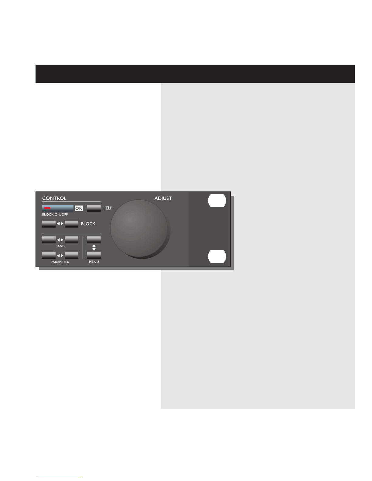
Keys, LED’s and other functions explained
Recalling a Preset, Factory/User Presets, Memory Card
Store a New Preset, The Letterbox
Input, EQ, Inserts, Normalizer, Expander, Compressor, Limiter, Output, Crossover Freq.
Phase Meter, Calibration Tone, Flow, Peak-Hold Meter, Digital I/O
Reset Page, User Data Page
Maybe you will find help here
Tutorial
5
6
8
9
10
12
13
14
28
32
33
34
36
37
38
39
40
41
42
Page 4

4
PRECAUTIONS
WARNING - THIS APPARATUS MUST BE EARTHED
Use only a three wire grounding type line cord,
like the one supplied with the Finalizer.
Be advised that different operating voltages require the use of a
different type line cord and attachment plug.
In doubt contact your TC distributor.
Check the voltage in your area and use the correct type.
See table below:
CAUTION - Do not open the Finalizer.
Risk of electric shock inside. There are no user-serviceable
parts inside. Refer servicing to qualified service personnel only.
Mount the Finalizer with a little space above and below in a
well ventilated rack. Don't block the top or bottom.
To prevent electrical shock or fire hazard, do no expose the
Finalizer to rain or moisture.
Do not rely solely on the front screws when mounted in touring
rack. Support the back of the Finalizer as well.
Please report any shipment damage or equipment malfunctions
to your dealer, TC distributor or the TC head office in
Denmark.
Voltage Line plug according to standard
110-125V UL817 and CSA C 22.2 no. 42
220-230V CEE 7 page VII,
SR section 107-2-D1/IEC 83 page C4
240V BS 1363 of 1984. Specification for 13A.
fused plugs and switched and
un-switched socket outlets
Page 5
5
WELCOME
Congratulations on the purchase of your new Finalizer.
We hope that you will have as much pleasure using it
as we had making it.
The general control is accomplished by moving the cursor using
the PARAMETER keys.
Jumping between bands using the BAND keys.
Changing block by using the BLOCK keys.
Change page using the MENU keys and decrease/increase values
by turning the ADJUST wheel.
The rest is simple. You select the area that you wish to control by
pressing the function keys on the front of the Finalizer; i.e., if
you want to recall, you press the RECALL key.
About this Manual
Many people in the music business have an aversion to reading
manuals. We understand that. So, if you feel like starting without
reading the whole manual, simply Plug & Play. You can always
use the manual for checking out areas that you have questions
about, or if you want to dig deeper into the unit, refer to the
Table of Contents for further information.
On the other hand, you might want to know a little more about
the Finalizer before you start pressing keys. The manual will take
you step by step through all of the Finalizer’s functions. If you
want to read about a specific function, please refer to the Table of
Contents.
Page 6
6
FRONT PANEL
Input PPM Gain
Reduction
Meters
Limit
LED’s
Expander
Active
Indicators
INDICATORS
Overload
Lights up if internal overload
occurs.
Sample Rate Indicator
48000 Hz
44100 Hz
32000 Hz
MIDI In
MIDI receive indicator.
Card
Indicates presence of a valid
memory card.
Working
Indicates that some calculation is going on.
Edited
Preset has been edited.
PC Card slot
Presets may be copied
to/from a standard memory
card.
Electronic power switch
»Easy touch«
Keep pressed for more than
1 second to turn device off.
Output PPM
High resolution meters
SoftClip LED
Indicates that output is clipped
Page 7
7
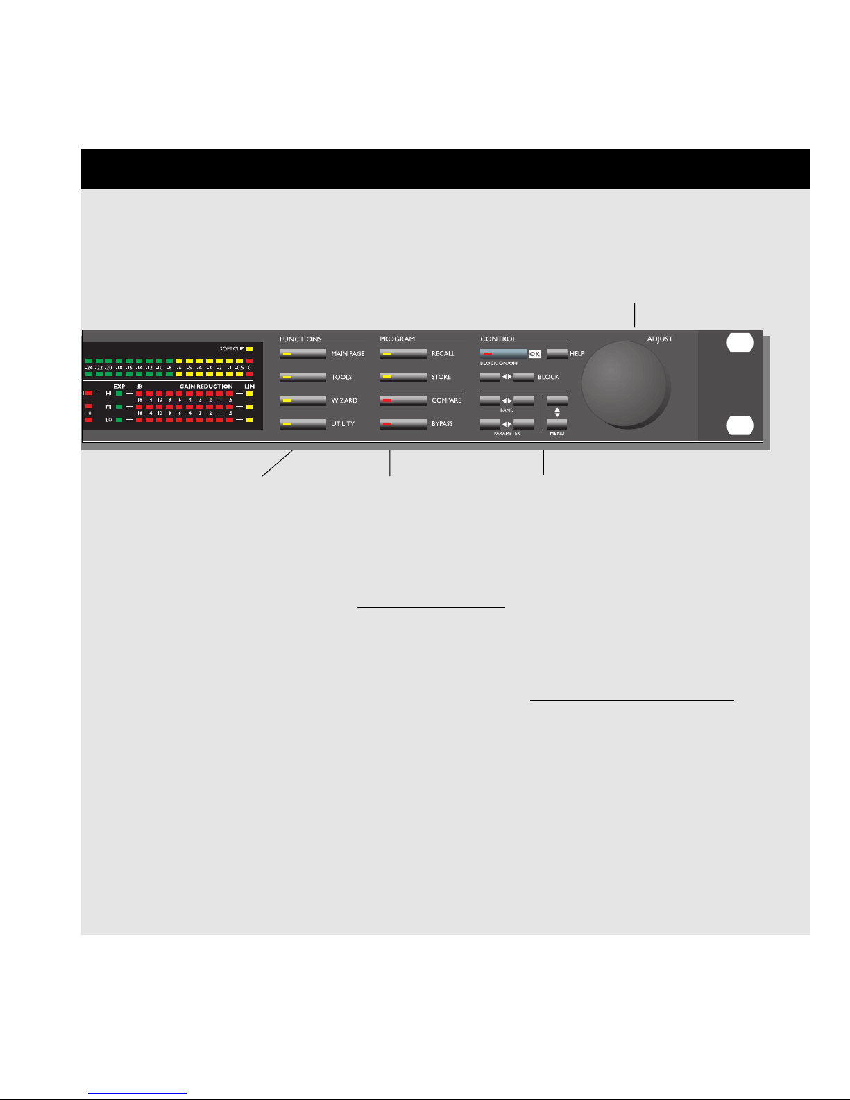
FUNCTIONS SECTION
Main Page
This button gives you
access to edit the entire
signal flow, from input to
output.
Tools
This key gives you access
to a lot of useful tools for
optimizing your material.
Wizard
The Wizard will do some of
the hard work for you.
Utility
MIDI, Security, Memory
management and much
more is located here.
PROGRAM SECTION
Recall
Recall presets.
Store
Store and name presets.
Compare
Compare the sound you
have right now with either
a leveled bypass or the
original preset.
Bypass
Bypass the signal processing.
CONTROL SECTION
OK
Confirm operations
and switch individual blocks on/off.
Help
Get help on selected display function
Block < >
Select which block to edit on the
main page.
Menu up/down
Vertically oriented menu selector.
Parameter < >
Moves horizontally for selection of
parameter to be modified.
Band < >
Select between the three bands on
the com/lim/exp pages.
On the EQ page, it selects which of the six
bands/level are displayed and ready for modification.
Adjust wheel
Sets parameter values and
preset numbers.
Page 8

8
REAR PANEL
Main
Power
Switch
Balanced
XLR
Inputs
Balanced
XLR
Outputs
Serial No.
AES/EBU
Digital
in/out
S/PDIF
Digital
in/out
MIDI
In,Thru,Out
Pedal/Fader
Input
NOTES:
To accommodate international regulations, we have also added a rear panel power switch.
You don’t need to use the power switch on the rear panel. Use the front panel power switch instead.
Pin 2 is »hot« on all XLR’s (IEC and AES standards).
If you are connecting the Finalizer to unbalanced equipment, you must tie pins 1 and 3 together in the cable
ends away from the Finalizer.
We have reserved the two unused pins on the MIDI connectors for an optional RS485 interface.
Therefore, if you are connecting the Finalizer to other equipment that use these pins, please make sure the
cable is a 3-wire standard MIDI type (not a five wire MIDIPLUS type).
If you want to use the pedal input, make sure it is a momentary »make« type.
Power
Input
Page 9
9
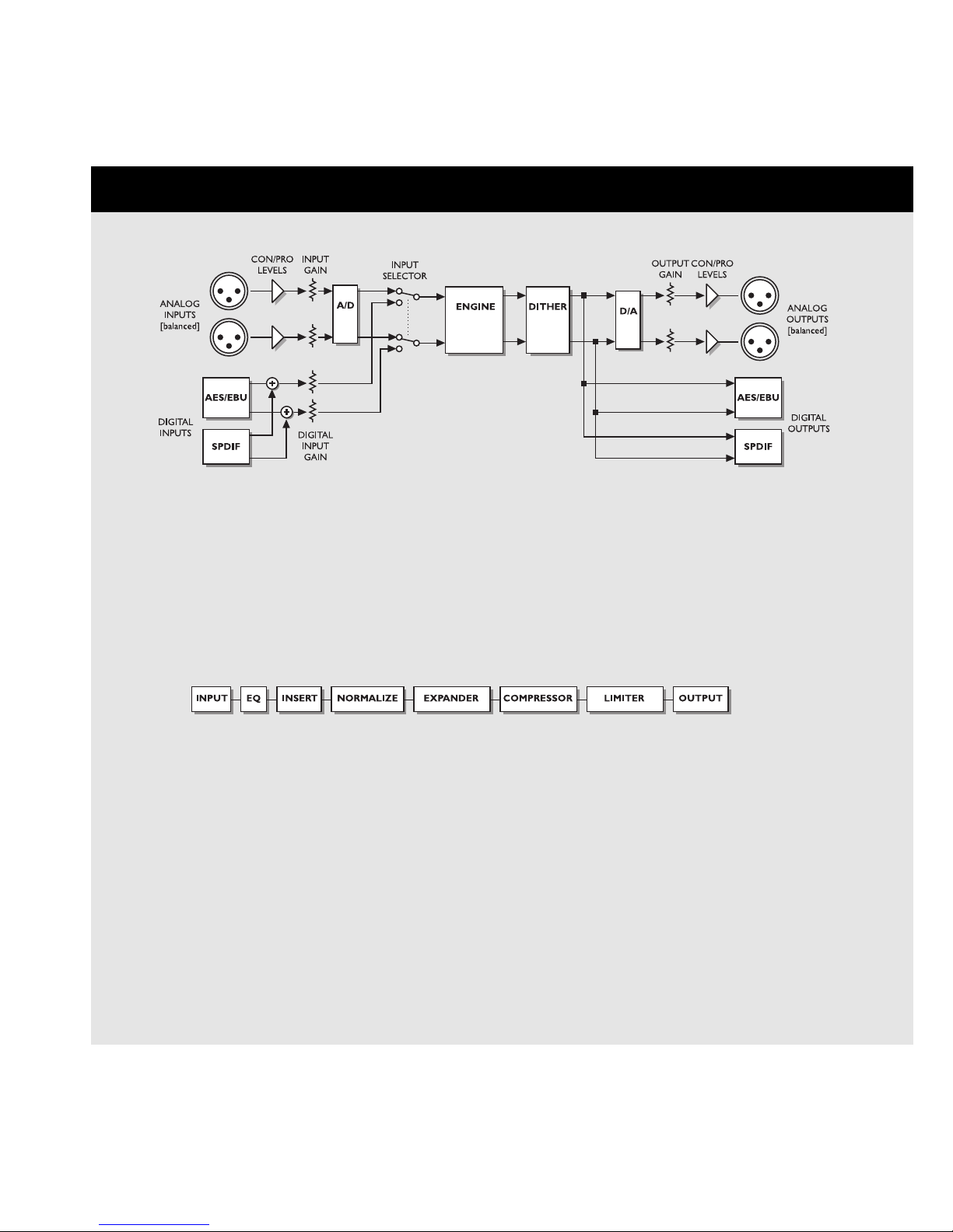
SIGNAL FLOW
Notes regarding the signal flow:
The AES/EBU and the S/PDIF inputs are connected internally. Therefore, do not connect cables to both
AES/EBU and S/PDIF inputs at the same time.
As you can see from the block diagram, signals are present on all outputs, all of the time. To make the
dithering circuit work appropriately, you must tell the system whether your main output is analog or digital
(the I/O menu).
Page 10

10
FINALIZER SETUP
Finalizer Setup
The Finalizer is carefully designed to optimize the overall level and enhance the energy in your mix.
The use of the three band compressor, limiter and expander makes the dynamics section of the Finalizer very flexible, while
maintaining the fidelity of the original material. The dynamics section, in a combination with a normalizer and a five band
equalizer, gives you a very powerful tool, to finish the last details of your mix.
Because the Finalizer can be used in different applications, we propose a couple of different setups.
Page 11
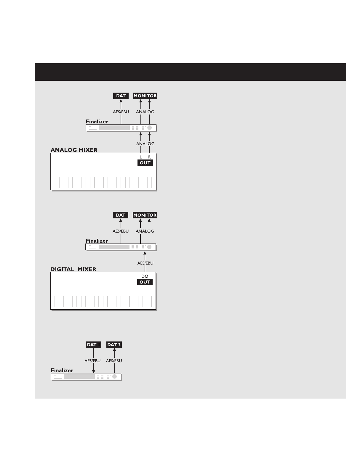
11
Setup with an analog mixing console and a digital
recording device.
1. Connect the analog output of your mixer to the analog input of
the Finalizer.
2. Connect the digital output of the Finalizer to your
digital recording device.
3. Connect the analog output of the Finalizer to your
monitor system.
Example 1
Example 2
Example 3
Setup with a digital mixing console and a digital
recording device
1. Connect the digital output of your mixer to the digital input of
the Finalizer.
2. Connect the digital output of the Finalizer to your
digital recording device.
3. Connect the analog output of the Finalizer to
your monitor system.
Mastering from DAT to DAT
1. Connect the digital output of DAT #1 to the digital input
of the Finalizer.
2. Connect the digital output of the Finalizer to the digital
input of DAT #2.
Page 12

12
Preset banks
Factory
Presets
Your own
Presets
The Finalizer contains two different preset banks.
The RAM bank can hold up to 128 presets.
The RAM preset bank is located after the ROM bank. This
means that you scroll through the ROM presets to enter the RAM
bank.
For fast RAM/ROM access use the BLOCK keys
to switch between the two banks.
Note: When previewing in the RAM bank you will not see the
empty RAM space.
Factory/User Presets
RECALL
Select which blocks will be loaded
from new preset.
Preset name
Preset number
ROM bank RAM bank
Recall
When you wish to recall a preset, simply use the ADJUST wheel
to scroll through the presets and press OK to recall.
The OK key will be blinking while you are previewing, indicating that the shown preset is not recalled yet.
It is also possible to recall separate sections of a preset. Select the desired section, using the PARAMETER
keys, and press OK.
The Recall Display
In the Recall display, you will see an information section at the
bottom of the screen. In this section you are able to see which
blocks are turned on in the current preset, and also a small EQ
preview with a miniature icon of the EQ setting.
In the upper right corner, you see an indication of which bank
you are previewing.
Short info about preset
128 RAM
PRESETS
ROM
PRESETS
Page 13
13
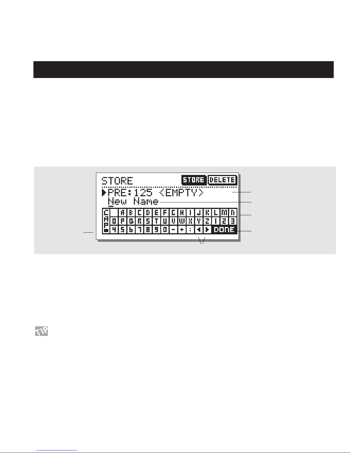
STORE
Store a New RAM Preset
- Press the STORE button
- Select a location for your new preset [dial between preset 1 to 128]
- Move the cursor to the new name line and dial in the new preset name [find letter with ADJUST and confirm with OK ]
- Move the cursor to DONE and press OK to finalize store operation.
Store with the same name:
If you want to store the preset with the existing name, simply select the RAM location to store it in by using the ADJUST wheel and press
OK (the OK key will be blinking while you search for a suitable RAM space). The Finalizer will now tell you “STORED” in a pop-up window and return to the main page.
Store location
The Letterbox
When you want to change the name of the preset to store, press
the MENU down key. You are now able to write a new name
using the letterbox. Simply dial the ADJUST wheel and press OK
to select new letters.
Select CAP, by pressing OK, to change case.
When you have changed the name, select DONE in the Letterbox
and press OK to Store.
You can use the PARAMETER keys to move the
cursor.
Delete a Preset
When you want to delete a preset, simply select Delete using the
BLOCK keys, select the preset to be deleted, and press OK.
New preset name
Letterbox
Cursor arrows
CAPS LOCK
Indicator
Place cursor here and press OK
to finalize store operation
Using a Memory Card:
When you wish to use a memory card, simply insert the card in
the Finalizer. The Finalizer will now autodetect your card and the
Store and Recall facilities will be attached to the memory card.
The Finalizer will now use the memory card as a normal RAM
bank. When you remove your memory card, the Finalizer will
switch back to the internal RAM.
If the format of the memory card is not correct, the Finalizer will
detect this immediately.
Card types
Type 1 PC Cards with minimum 64 KBytes of SRAM.
Page 14

14
MAIN PAGE Input
Set input levels Select
input
Sample Rate:
44.1kHz, 48kHz
or from Digital Input
LowCut Filter
Select between con/pro
analog input levels.
Select the IN section on the Main page by pressing the
BLOCK keys.
These global level controls should be set to optimize the performance of the 20 bit A to D converter in the Finalizer.
Basic operation
Press the PARAMETER keys to move the cursor, and turn the
ADJUST wheel to change values.
Left & Right
The input bars can be operated individually or in common.
Highlight both bars for common operation by pressing the
PARAMETER keys. The range of the input bars depends on the
input type (Analog/Digital) and the input level
(Professional/Consumer).
Note: The input bars are always common when digital input is
selected.
Ranges
Analog Inputs
Consumer (-10 dBu): -16 dB to +10 dB
Professional (+6 dBu): -6 dB to +16 dB
Digital Inputs -16 dB to +6 dB
Sample Rate (Srate): Select master clock
44.1 kHz/48 kHz/DI
When Digital Input is selected, the external clock frequency will
be displayed by the three LEDs on the left hand side of the display. If the Finalizer can not lock, none of the LEDs will be lit.
Note: When changing the input to digital, the sample rate parameter is automatically set to DI.
LowCut
The lowcut filter is global, and is used to filter out any sub-bass
frequency or DC contents in the current signal.
Page 15

15
MAIN PAGE EQ
Effects blocks
Black box indicates selected block
EQ on/off
Parameter
Band
Output Level bar
Selected band
Frequency
Gain
Bandwidth/Slope
EQ
Select EQ by pressing the BLOCK keys.
Basic operation
Press PARAMETER keys to select frequency/gain/bandwidth/slope.
Turn ADJUST wheel to change values.
Press BAND keys to jump between the five bands.
EQ Ranges
Frequency Gain Bandwidth/Slope
Low Shelve 19.95 Hz to 5.01 kHz +/- 12 dB 3, 6, 9, 12 dB/Oct
Bell-shaped filter 1 19.95 Hz to 20 kHz +/- 12 dB 0.1 Oct to 4.0 Oct
Bell-shaped filter 2 19.95 Hz to 20 kHz +/- 12 dB 0.1 Oct to 4.0 Oct
Bell-shaped filter 3 19.95 Hz to 20 kHz +/- 12 dB 0.1 Oct to 4.0 Oct
High Shelve 501.2 Hz to 20 kHz +/- 12 dB 3, 6, 9, 12 dB/Oct
Output Gain - +/- 12 dB -
EQ Bypass
Press the blue BLOCK on/off key to bypass the EQ section.
Reset all filters by pressing both page keys simultaneously.
Page 16

16
MAIN PAGE Inserts
Insert type selector
Select between:
- None
- Digital Radiance
- Stereo Adjust
- De-essing
Insert selected
This parameter deter-
mines the drive of the
Radiance Generator.
If your material is asymmetric
(percussion/speech etc.) this
parameter will change the
sound.
Move cursor up to increase the stereo width.
Move cursor down to make the signal more mono.
Center position is normal.
Move the cursor right/left to adjust center (balance)
STEREO ADJUST
DIGITAL RADIANCE GENERATOR
THRESHOLD
RATIO
ATTACK
RELEASE
FREQUENCY sets the cutoff freq.
of the de-esser.
CURVE sets the frequency characteristics of the dynamic damping filter.
DE-ESSER
Page 17

17
MAIN PAGE Inserts
Inserts
Select Insert by pressing the BLOCK keys
The Finalizer has various insert possibilities. Choose between
DRG, Stereo Adjust or De-essing by pressing the MENU
up/down keys.
Note: You can use only one insert function at a time.
Basic operation
- Use MENU keys to select insert effect.
- Press the PARAMETER keys to select parameter.
- Turn the ADJUST wheel to change values.
Stereo Adjust
With Stereo Adjust, you can change the stereo information of the
signal. Turn the MS parameter clockwise to increase stereo width
and counter clockwise to make the signal more mono-like.
You can change the left/right balance with the LR parameter.
De-esser
This algorithm removes unwanted »esses« from vocal material
by dynamically reducing the level of high frequencies.
Threshold
Use the ADJUST wheel to change the threshold of the de-esser.
Attack
Use the ADJUST wheel to change the attack time of the de-esser.
Release
Use the ADJUST wheel to change the release time of the deesser.
Ratio
Use this parameter to adjust the damping ratio of the de-esser.
Frequency
The frequency sets the cut-off frequency of the de-esser.
Curve
With the curve parameter, you select whether the de-esser should
work with a bell-shaped or shelving filter.
Digital Radiance Generator
The DRG (Digital Radiance Generator) adds second harmonic
distortion to the signal. This kind of distortion is very analoglike, and will add a certain warmth to your material.
Drive
The DRG drive is adjustable from 0 to 10.
Curve
If your material is asymmetric (percussion/speech, etc.), the
plus/minus parameter will change the sound of the DRG.
Page 18

18
Page 19

19
MAIN PAGE Normalizer
Effects blocks
Black box indicates selected block
No. of consecutive
samples clipped.
Normalizing gain
Clipping method
Normalizer
Optimizing the level of your material starts in the Normalizer.
Here you have a graphical presentation of the incoming signal, shown as 1 second pictures.
By increasing the gain, you decrease the headroom, shown as two dotted lines.
You should set the gain such that the signal peaks are just hitting the dotted headroom lines.
The Normalizer is capable of gaining +18 dB.
The Clipper
The Normalizer has a build-in limiter, which can be either soft or hard. When the Normalizer limiter is active, it is indicated on the
Normalizer LIM LED above the Input Meters.
The Clip Counter indicates the maximum number of consecutive samples clipped within the last second.
If the clips only occur occasionally, and only few samples are clipped per test interval, you do not necessarily have to reduce the gain of the
Normalizer.
Page 20

MAIN PAGE Expander
Y-axis is output
level.
USER PAGE
EXPERT PAGE
Arrow direction indicates
whether the parameter value
has been increased or
decreased since last recall.
PAGES
- User page
- Expert page
- Cross-over frequency page
X-axis is input
level.
Expander
threshold
low/mid/high
Attack time
low/mid/high
Release
time
low/mid/high
Side chain / delay
This parameter inserts the indicated delay in
the main signal path.
The side chain will therefore be able to look
ahead on the input signal, enabling it to
respond faster to sudden signal changes.
This parameter is common for expander/compressor/limiter.
Ratio
low/mid/high Use band select cursors to access
individual bands.
CROSS-OVER FREQUENCY PAGE
20
Page 21

21
Expander
Select EXP by pressing the BLOCK keys
Basic Operation
- Press the PARAMETER keys to select parameter.
- Turn the ADJUST wheel to change values.
- Press the BAND keys to select between the three bands.
- Press the MENU keys to select User/Xpert/Xover.
User Menu
Threshold
Use the ADJUST wheel to change the thresholds of the three
bands.
Ratio
Use these parameters to adjust the ratios of the three expander
bands.
Expander Monitor
The Expander Monitor gives you a graphical picture of the ratio
and threshold settings.
Expert Menu
Press MENU keys to enter expert mode (XPRT)
Attack
Use the ADJUST wheel to change the attack time of the three
bands.
Release
Use the ADJUST wheel to change the release time of the three
bands.
Side Chain / Delay
This parameter adjusts the “look-ahead” delay. This means that
your audio signal is delayed, i.e., 10 ms.
By slightly delaying the audio signal, you give the processor a
chance to look ahead at the present signal, and will therefore
react more accurately than a standard
compressor/limiter/expander.
The actual look-ahead delay time is scaled with the attack time
individually on all three bands.
Note: This delay time parameter is common for the compressor,
limiter and expander.
Cross-over Menu
Press MENU keys to enter the cross-over frequency
page (Xovr)
L-Xovr/H-Xovr
With the L-Xovr and H-Xovr you set the cross-over points of the
three bands in the dynamics section.
Note: The cross-over points are common for the compressor, limiter and expander.
The Edit Guide
The symbol in the lower left corner of the display is an edit
guide. This indicator will help you get back to parameter values
of the latest recalled preset.
Arrow direction indicates whether the parameter value
has been increased or decreased since last recall.
Example:
If you have been working on various parameters within a preset
and would like to get the original ratios back without changing
the attack/release times, simply select the ratio parameters one
by one and follow the edit guide.
Expander Bypass
Press the blue BLOCK on/off key to bypass the expander section.
Page 22

22
MAIN PAGE Compressor
USER PAGE
EXPERT PAGE
Page select:
1. User page
2. Expert page
3. Cross-over page
Threshold
low/mid/high
Ratio
low/mid/high
Band levels
low/mid/high
Output level
Attack
Times
low/mid/high
Release
Times
low/mid/high
Crest
This parameter determines
wether the compressor
should react to peaks,
RMS (average), or something in between.
Side chain / Delay
(same as under
expander)
CROSS-OVER FREQUENCY PAGE
Arrow direction indicates
whether the parameter value
has been increased or
decreased since last recall.
Page 23

23
The Compressor
Select COM by pressing the BLOCK keys
Basic operation
- Press the PARAMETER keys to select parameter.
- Turn the ADJUST wheel to change values.
- Press the BAND keys to select between the three bands.
- Press the MENU keys to select User/Xpert/Xover.
About the Compressor
The compressor section of the Finalizer is divided into three
bands. This means that you are able to compress the
low/mid/high frequencies separately.
To optimize the output gain and energy in your material, the
Finalizer uses auto-makeup gain, meaning that the three bands
are gained individually and automatically, depending on how
hard the current band is compressed.
User Menu
Threshold
Use the ADJUST wheel to change the thresholds of the three
bands.
Ratio
Use these parameters to adjust the ratios of the three compressor
bands.
Band Level
The three band levels are used to adjust the spectral balance in
the compressor. You are able to change the level of the low, mid
and high bands individually, simply by selecting the current band
and turning the ADJUST wheel.
Out Level
With this parameter you can adjust the overall output of the compressor.
Expert Menu
Press MENU keys to enter the expert page.
Attack
Use the ADJUST wheel to change the attack time of the three
bands.
Release
Use the ADJUST wheel to change the release time of the three
bands.
Side Chain / Delay
This parameter adjusts the look-ahead delay. This means that
your audio signal is delayed, i.e., 10 ms.
By slightly delaying the audio signal, you enable the processor to
look ahead at the present signal, and it will, therefore, react more
accurately than a standard compressor/limiter/expander.
The actual look-ahead delay time is scaled automatically with the
attack time, individually on all three bands.
Note: This delay time parameter is common for the compressor,
limiter and expander.
Crest
This parameter determines whether the compressor should react
to peaks, RMS (average), or something in between. For example
if the crest parameter is set at 6 dB, the compressor is reacting to
RMS values and to peaks 6 dB higher than the current RMS
value.
Cross-over Menu
Press MENU keys to enter the cross-over
frequency page (Xovr)
L-Xovr/H-Xovr
With the L-Xovr and H-Xovr you set the cross-over points of the
three bands in the dynamics section.
Note: The cross-over points are common for the compressor, limiter and expander.
Compressor Bypass
Press the blue BLOCK on/off key to bypass the compressor section.
Page 24

24
MAIN PAGE Limiter
Expert mode on/off
Arrow direction indicates
whether the parameter value
has been increased or
decreased since last recall.
Limiter
threshold
low/mid/high
Bypass individual
limiter bands.
Clipping method
The clip function smoothly kills
any overshoot that might occur
after heavy compression or limiting. The higher the percentage,
the softer the clip.
USER PAGE
EXPERT PAGE
CROSSOVER FREQUENCY PAGE
Attack
Times
low/mid/high
Release
Times
low/mid/high
Digital ceiling
This parameter
reduces the full
scale (0dB) signal
level on the output.
Side chain / Delay
(same as under
compressor /
expander)
Page 25

25
The Limiter
Select LIM by pressing the BLOCK keys
Basic operation
- Press the PARAMETER keys to select parameter.
- Turn the ADJUST wheel to change values.
- Press the BAND keys to select between the three bands.
- Press the MENU keys to select User/Xpert/Xover.
User Menu
Threshold
Use the ADJUST wheel to change the thresholds of the three
bands.
On/Off
Use these parameters to enable/disable the three limiter bands.
Clip
The clip function smoothly kills any overshoot that might occur
after heavy compression or limiting. The higher the percentage,
the softer the clip.
Expert Menu
Press MENU keys to enter the expert page.
Attack
Use the ADJUST wheel to change the attack time of the three
bands.
Release
Use the ADJUST wheel to change the release time of the three
bands.
Side Chain / Delay
This parameter adjusts the look-ahead delay. This means that
your audio signal is delayed, i.e., 10 ms.
By slightly delaying the audio signal, you enable the processor to
look ahead at the present signal, and it will, therefore, react more
accurately than a standard compressor/limiter/expander.
The actual look-ahead delay time is scaled automatically with the
attack time, individually on all three bands.
Note: This delay time parameter is common for the compressor,
limiter and expander.
Digital Ceiling
With the digital ceiling you can adjust the digital maximum output, i.e., if you receive an overload indication on the device connected to the DI/out of the Finalizer, you are able to reduce the
output level down by 0.01 dB increments.
Cross-over Menu
Press MENU keys to enter the cross-over frequency
page (Xovr)
L-Xovr/H-Xovr
With the L-Xovr and H-Xovr you set the cross-over points of the
three bands in the dynamics section.
Note: The cross-over points are common for the compressor, limiter and expander.
Page 26

26
MAIN PAGE Output
Analog
output level
(left and right)
Select
primary
output
Select no. of bits dithered to:
8 bit
16 bit (default for SPDIF)
18 bit
20 bit (default for analog out)
24 bit (default for AES)
FADE SECTION
CURVE sets the fade-out curve
TIME sets the fade-out time
FADE up/down/stop
LEVEL set fader level manually.
Note:
If an external fader is connected, all of the above
parameters are disabled.
Select the OUT section in the main page by pressing
the BLOCK keys
Primary Output
When selecting your primary output, the Finalizer automatically
selects a suitable dither.
If you select ANALOG, the Finalizer dithers to 20 bit
(the D to A converters are 20 bit).
If you select S/PDIF, the Finalizer dithers to 16 bit.
If you select AES/EBU, the dither is off, meaning that 24 bit raw
data is sent out of the Finalizer digital outputs.
Note: There is always signal present on both analog and digital
outputs.
Dither
With the dither parameter you can select the desired dither type
yourself. Select between: 8, 16, 18, 20, 22, 24 (off).
Note: The dither parameter is always reset when changing the
primary output.
Analog
Use the output bar for adjusting the analog output gain.
Range: -16 dB to +6 dB
Auto Fade
The Finalizer is capable of auto-fades up to 60 seconds.
Select the fade curve and the fade time.
To start the fade, select the fade up/down parameter and turn the
ADJUST wheel.
You also have the possibility of a manual fade, simply by selecting the LEV parameter and turning the ADJUST wheel.
The manual fade function can also be controlled by the TC
Master Fader.
Note: The pedal function in the Utility menu must be set to Fader
for external control.
Page 27

27
Page 28

28
TOOLS Phase Meter (correlation)
Time/division
Curve speed
TOOLS Calibration Tone
Phase Meter
The phase meter show you the phase relationship
between the two stereo channels.
Plus means that the two channels are in phase.
Minus means that the two channels are in antiphase.
Time/division
Sets the curve drawing speed.
Calibration tone
In the calibration display you have a 1000 Hz testtone, which will be sent out on the Finalizers outputs at the selected level.
Set the level by using the ADJUST wheel and press
OK to activate.
Page 29

29
TOOLS Flow
Internal levels (ppm)
TOOLS Peak-Hold Meter
Numeric readout of peak values
Flow
In the Flow Meter, you have six small peak meters,
representing the level in the different sections of
the Finalizer.
This can be very helpful in a number of situations.
I.e. you have an overload indication on the front,
but you do not know in which section the overload
is located: now you simply press TOOLS and select
the Flow meter, and you have instant view of all
levels and possible overloads in the Finalizer.
Peak
The Peak-Hold Meter is an output meter with infinite hold. It is possible to see the level of the maximum peak in 0.10 dB precision.
Press OK to reset the meter.
Page 30

30
TOOLS Digital I/O (DIO)
Pre-emphasis indicator: on/off
RECEIVED STATUS BITS
DIGITAL OUT STATUS BITS
Copyright
Here you can set the copyrights
on the outgoing digital audio.
Source device: DAT, CD, mixer etc.
Numbers of audio bits received.
Copyright: None, One copy only , Infinite copies
Status bits on digital output:
AES/EBU: Professional usage of status bits.
S/PDIF: Consumer usage of status bits.
FROM INPUT: Status bits received on input are
fed through to the digital output.
Page 31

31
TOOLS Digital I/O (DIO)
IN
On this display you have various indicators that tell
you what kind of digital signal you are receiving.
Pre-emphasis
This parameter tells whether the incoming signal is pre-emphasized or not.
Source device (Category code).
The device status of the received signal is shown in this indicator.
Audio data
The number of received audio bits is indicated here.
Copyright (Copy inhibit).
Status of the copybits.
OUT
On this display you set up how the Finalizer should
send out your material.
COPY ENABLE
Set the copyrights of your material:
- No copies
- 1 copy only
- Infinite number of copies.
Note: The copy protection is only valid with S/PDIF signals.
STATUS BITS OUT
AES/EBU
When AES/EBU is selected the Finalizer will send out its own
professional set of status bits, meaning that any incoming ID will
be lost. However, in order to take full advantage of the
Finalizer’s 24 bit resolution you should select AES/EBU to make
sure that the receiving device after the Finalizer will accept all 24
bits.
S/PDIF
When S/PDIF is selected, the Finalizer will send its own consumer status bits out, meaning that any incoming ID will be lost.
The Finalizer’s S/PDIF output carries up to 20 bits. Only the
S/PDIF signal contains copy protection information.
From Input
When this setting is selected the Finalizer will send the same
information out as it received. However, you still have the possibility to change the copy status.
Page 32

32
WIZARD
Select source type: soft/medium/hard
Select degree of compression:
soft/medium/hard
Optimize gain
If this option is selected the Finalizer will adjust
the Normalizer level.
Press OK to start procedure
EQ
The Finalizer will adjust the Equalizer to the selected
spectral expression.
Wizard -
Making the whole thing very simple
Press the WIZARD key.
With the Wizard you set a couple of terms, and the Wizard will select the optimal settings for you: the Normalizer, Compressor, Limiter and
EQ.
Select whether your source type is soft, medium or hard, using the ADJUST wheel.
Select which kind of compression you like: Soft, medium or hard.
Do you want your material to be gain optimized? Yes or no.
Note: If you use auto-gain, the Wizard will be measuring until you stop it.
This means that you can run all of your material through the Wizard to get the optimum level.
Select which EQ setting you would like: Flat (no EQ), Loudness, Bass-lift or Air.
Press the OK key to carry out the settings of the Wizard.
Press any key to stop the Autogain function.
Page 33

33
COMPARE
Compare
The reason for adding this compare function is that it can be difficult to estimate what the EQ/dynamics is doing to the sound of your material. Because of the extra gain of the Normalizer and the compressor in-circuit and out-of-circuit comparisons are often difficult to make
using the BYPASS key.
That is why we made it possible to reduce the level of your processed setting when comparing it with the bypassed sound. You can even
compare with the last recalled preset.
Press the COMPARE key and use the ADJUST wheel to lower the level of your setting.
Then use the PARAMETER keys to compare these different sounds: one, the original; two, your edited preset; or three, the bypassed signal.
Listen to original preset
If you place cursor here, you will hear
the original preset.
Listen to your edited sound
If you place the cursor here, you will
hear the edited sound.
Use the ADJUST wheel to adjust this
level for better comparison with the
bypassed signal.
Bypassed signal
Same function as the BYPASS key.
Page 34

34
UTILITY
Display
Viewing Angle
Adjust for best contrast on the LCD display.
MIDI In
Channel
Sets the receive channel of the Finalizer.
When set to Omni the Finalizer will respond to all channels.
When set to Off no MIDI will be received.
Prg. Change
Sets whether the Finalizer should respond to MIDI program
changes or not.
Controllers
Sets whether the Finalizer should respond to MIDI controllers or
not.
Prg. Offset
This number is added to the incoming program number.
Example:
If the incoming program number is 10, and the offset is set to -1,
the Finalizer will change to program 9.
Program Bank
If this parameter is set to RAM, all received MIDI program
changes will recall user (RAM) presets.
If set to ROM, received MIDI program changes will recall factory (ROM) presets.
System Exclusive ID (SysEx ID)
System exclusive ID number of the Finalizer.
How to move around
In the UTILITY menu you always move by pressing the
MENU keys and change values by dialing the ADJUST
wheel.
Page 35

35
Memory Protect
Protect
This parameter sets the memory protection on or off. When protect is on, the RAM presets between the high and low limits are
write protected.
Memory Backup
Mem > Card
Insert a PC Card in the card slot and press OK. All RAM presets
of the Finalizer will now be backed up to the memory card.
Card > Mem
Insert the PC Card containing your presets and press OK. All
presets will now be stored back into the Finalizer RAM.
Warning:
This action will destroy all existing RAM presets of the Finalizer.
Mem > MIDI
Connect your Finalizer’s MIDI output to another Finalizer, a
sequencer or any other MIDI recording device. Press OK and the
Finalizer will perform a MIDI bulk dump of all RAM presets.
MIDI > Mem
Connect the storing device to the Finalizer’s MIDI input and
press OK. The Finalizer is now ready to receive a MIDI bulk
dump containing RAM presets.
Warning:
This action will destroy all existing RAM presets of the Finalizer.
Pedal Input
Select between: External Fader/Fade up-down/Bypass.
MIDI Out
Channel
MIDI transmit channel.
Prg. Change
Sets whether the Finalizer should transmit MIDI program
changes or not.
Controllers
Sets whether the Finalizer should transmit MIDI control changes
or not.
Offset
This number is added to the outgoing program number.
Security
To security-lock the Finalizer, press OK while this parameter is
selected.
When locked, you will have to dial the PIN-code shown below
to access the Finalizer.
PIN-code
Sets your PIN-code for the security lock by dialing the ADJUST
wheel (See page 36).
If you should forget your PIN-code, please enter the Reset page.
This will release the Finalizer from the locked state.
(You do not have to run any of the reset functions).
Page 36

36
RESET PAGE
How to enter the Reset page:
Hold the BYPASS key pressed while powering up.
Move the marker using the MENU keys and press OK
to select reset type.
Load User Default
This will reset all system parameters back to a default setup made
by you (see Store User Def.). This reset will NOT delete the user
presets of the Finalizer.
Store User Def.
When you have a perfect setup of your Finalizer, you are able to
store this as your own default setup. This function is very useful,
for example when you have finished a special production and
want to go back to normal. When you have the perfect setup of
your Finalizer, simply select this parameter and press OK to store
your default settings.
The User Default includes all system parameters.
Set User Name
This function makes it possible to write your name and phone
number into the Finalizer. Press OK to access the user data menu.
Use the ADJUST wheel and the MENU keys to write your name
and phone number into the Finalizer. Press OK to accept. Your
name and phone number will be displayed during power-up.
Reset System Parameters
This will reset all system parameters back to the factory default.
This reset will NOT delete the user presets of the Finalizer.
Reset all Presets
This will clear all RAM presets.
Store and load your own
default settings
Enter User data page
Reset system parameters
Clear all user presets
Test Programs
Type your name here
and your phone number
Place cursor here
and press OK to
finalize session.
Page 37

37
TECHNICAL SPECIFICATIONS
Analog Input
Connectors: XLR balanced (pin 2 hot)
Impedance: 15 kOhm
Max. Input Level: +22 dBu
Sensitivity: @ 12 dB headroom: -22 dBu to 10 dBu
A to D Conversion: 20 bit (4 bit, 64 times oversampling)
Dynamic Range: > 105 dB
THD: < 0.003% @ 1 kHz, +10 dB
Frequency Response: 10 Hz - 20 kHz: +0/-0.2 dB
Crosstalk: -60 dB max, 10 Hz to 20 kHz
Analog Output
Connectors: XLR balanced (pin 2 hot)
Impedance: 100 Ohm (active transformer)
Max Output Level: +22 dBu
Output Gain Range: 0 to -32 dB
D to A Conversion: 20 bit (1 bit 128 times oversampling)
Dynamic Range: > 96 dB
THD: < 0.008% @ 1 kHz, +10 dB
Frequency Response: 10 Hz - 20 kHz: +0/-0.3 dB
Crosstalk: -60 dB max, 10 Hz to 20 kHz
Digital Inputs and Outputs
AES/EBU In/Out: XLR
S/PDIF In/Out: Coaxial, RCA Type
Formats: EIAJ CP-340, IEC 958, S/PDIF (20 bit)
AES/EBU (24 bit)
Sample Rates: 32 kHz, 44.1 kHz and 48 kHz
PC-CARD Interface
Connector: Type 1 PC Cards
Standards: PC-CARD 2.0, JEIDA 4.0
Card Format: Supports up to 2 MB SRAM
Control Interface
MIDI: In/Out/Thru: 5 Pin DIN
Pedal: 1/4 inch phone jack
General
Finish: Black anodized aluminum face plate
Painted and plated steel chassis
Dimensions: 19” x 1.75” x 8.2” (485 x 45 x 195 mm)
Weight: 5.2 lbs (2.35 kg)
AC Power: 90 - 240 VAC without switch settings
3 Pin IEC power connector
Battery Life: >10 years
Radio Frequency Immunity/Interference
RFI/ESD: Conforms to FCC Class B,
EN55103-1 (CE), EN55103-2 (CE)
Environment
Operating Temperature: 32
O
F to 122OF (0OC to 50OC)
Storage Temperature: -22
O
F 167OF (-30OC to 70OC)
Humidity: Max. 95% non-condensing
All specifications are subject to change without notice.
Page 38

38
TROUBLESHOOTING
You press the POWER switch but there is no light.
- The power switch on the rear panel is switched off.
The input PPM meters don’t peak out.
- You are using analog inputs, but the input selector in the I/O menu is set to digital in.
- The analog input level is set too low.
No sound through the Finalizer
- You are using analog inputs, but the input selector in the I/O menu is set to digital in.
You cannot turn the power off.
- Hold the power switch pressed for at least 3 seconds.
Page 39

39
MIDI IMPLEMENTATION CHART
STUDIO MASTERING PROCESSOR: Finalizer - JUNE 24, 1996 Version 1.0
Function Transmitted Recognized Remarks
Basic Channel Default 1 1
Changed 1-16 1-16
Mode Default
Messages X X
Altered
Note Number XX
True Voice X X
Velocity Note ON X X
Note OFF X X
After Touch Key’s X X
Ch’s X X
Pitch Bend XX
Control Change OO
Prog Change OO
True# 0-127 0-127
System Exclusive OO
Common :Song Pos X X
:Song Sel X X
:Tune X X
System real time :Clock O O
:Commands X X
Aux Messages :Local ON/OFF X X
:All Notes OFF X X
:Active Sense X X
:Reset X X
Notes
O:YES Mode1: OMNI ON, POLY Mode 2: OMNI ON, MONO
X:NO Mode 3: OMNI OFF, POLY Mode 4: OMNI OFF, MONO
Page 40

40
SELF TEST
PRESS ONE OF THE 3 BYPASS KEYS, WHILE POWERING UP, TO ACCESS THE SELF-TEST AND SELECT
»RUN TEST PROGRAM«
Turn the ADJUST Wheel to scroll through self tests
Key test
Select Key test by pressing OK.
The keys must be pressed in the order they are requested by the
Finalizer to pass the test.
Press OK key again to exit test.
Adjust Wheel test
Select Adjust Wheel test by pressing OK
Turn the Adjust Wheel to 30 and back to 0 to pass test.
Press OK key again to exit test.
LED test
Select Led test by pressing OK
Turn Adjust Wheel to test the LEDs. The test is “ok” when all
LEDs are lit.
Press OK key again to exit test.
Display test
Select Display test by pressing OK
Press OK to check that all pixels are lit. Press any key to leave
the pixel test.
Press OK key again to exit test.
Analog I/O test
Select Analog I/O test by pressing OK
Connect an analog output to the analog input, which has to be
tested and press OK.
Use a balanced cable.
PPM must show -12 dB to pass test.
Press OK key again to exit test.
Digital I/O test
Select Digital I/O test by pressing OK
Connect a digital output to the digital input, which has to be tested and press OK.
The AES/EBU output can also be connected to the S/PDIF input
and vice versa.
PPM must show 0 dB to pass test.
Press OK key again to exit test.
MIDI I/O test
Select MIDI I/O test by pressing OK
Connect MIDI out to MIDI In.
Prg. change 1-128 is send out on MIDI thru. Connect this socket
to a MIDI compatible device and confirm the Prg. changes.
Press OK key again to exit test.
Pedal test
Select Pedal test by pressing OK.
Connect a momentary pedal to the pedal socket.
When pressing the pedal, the result should be OK.
When released, the result should be NOT OK.
Press OK key again to exit test.
PC Card test
Select PC Card test by pressing OK
Insert PC Card. Note that all data on the PC Card will be
destroyed.
Press OK to test.
Result reads:
Low battery - Time to change battery in your PC Card.
Not Ok - Try the test using another PCMCIA card.
Press OK key again to exit test.
Battery test
Select Battery test by pressing OK
Confirm that result is OK.
Press OK key again to exit test.
System test
Select System test by pressing OK
Confirm that result is OK.
Result reads:
EEPROM Not OK - The unit will most likely work ok, the message is for service matters only.
DSP Not OK - Contact your local dealer.
Press OK key again to exit test.
Power Off - On to start standard software.
Page 41

41
GLOSSARY
AES/EBU
Professional digital in/out standard, using balanced XLR cables.
S/PDIF
Consumer digital in/out standard, normally using coaxial phonotype cables.
DITHERING
Dithering is a method to optimize the quality of a digital audio
signal at low levels. A small amount of filtered noise is added to
the signal, giving you a less distorted low level signal.
To make the dithering circuit work optimally, you need to tell the
system which output you use. If you are using the analog outputs,
dithering should always be set to 20 bits. If you are using digital
outputs, the equipment you feed determines the number of bits. A
DAT or CDR recorder should always be dithered to 16 bit.
PRO/CON LEVELS
Depending on which equipment you are using along with the
Finalizer, you must set the PRO/CON parameters correctly in the
I/O setup menu.
Finalizer Analog Inputs:
Consumer range: -16 dB to +10 dB, nominal level = -10 dB
Professional range: -6 dB to +16 dB, nominal level = +4 dB
Finalizer Analog Outputs:
Consumer range: -10 dB to +16 dB
Professional range: -16 dB to +6 dB
The levels are either listed in the technical specifications or
printed on the rear panel of the connected devices.
DE-ESSING
An algorithm that removes unwanted »esses« from a vocal material.
SYSTEM EXCLUSIVE MIDI COMMANDS
Device-dependent MIDI commands, normally used for remote
controlling machines.
Page 42

42
APPENDIX Tutorial
Finalizer Tutorial
The basic idea with the Finalizer is to touch up the last details of
your mix and enhance the energy and level, in order to make it
sound punchier and louder.
As there are different approaches to the Finalizer, we created this
tutorial to familiarize you with the Finalizer.
The mainpage of the Finalizer shows you the signal flow, and the
actual order of the processor you are working.
The Input
Select your type of input: Analog or digital. If you are working
with an analog input you should use Pro/Con and the level bars to
optimize the performance of the A to D converter.
Remember to choose the right sample rate, i.e. if you targeting on
CD you should always choose 44.1 kHz.
Now recall the CD-Master preset, by pressing the RECALL key,
select CD-Master and press OK to recall.
The EQ
In the EQ you have the possibility, of changing the spectral
shape of your material.
Inserts
Select between Stereo adjust, De-essing or DRG.
Normalizer
Optimizing the level of your material starts in the Normalizer.
Here you have a graphical presentation of the incoming signal.
By increasing the GAIN, you decrease the headroom, shown as
two dotted lines.
You should set the GAIN such that the signal peaks are just
below or above the dotted headroom lines.
The Expander
The Expander is a great help in cleaning up the basic mix, either
as a soft expander or as a sharp gate.
Try to listen to the start of your mix, do you have any tape or
recording noise ?
If you have and you want to remove it, use the expander as follows:
Set the Ratio’s to 1:32, this is the steepness of the expander.
Now adjust the THRESHOLD so the expander only works when
the music is not there.
Play the music from the top a couple of times, and confirm that
the start is silenced.
If you only want to remove tape noise, it might be enough to use
the high band expander only.
The Compressor
The Compressor is the heart of the Finalizer. This section adds
that extra “punch” to your material.
When you are doing multiband compression, you have to do a
survey of the program material, i.e. Is there to much or too little
top-end or low-ende? Is the midrange well defined? A standard
situation could be that you have a mix which sounds good, but
lacks tightness and could use more of that “in your face” sound.
Now put the Finalizer in bypass, and recall the “CD-Master” preset. Start your mix and de-activate the Bypass. You will hear an
immediate change in the sound of your mix, because the “CDMaster” preset was designed to tighten up on almost all types of
rhythmic music that you hear today. In most cases, you will only
have to adjust the input level by using the Normalizer.
If you want to make changes to the over all relationship of the
low, mid, high bands using the Compressor, you have two paths
that you may take to accomplish this task. The first way is to alter
the bandlevels, using them like a three band equalizer. The second way is to individually compress the three bands. It is here, in
the multi-band Compressor, where you will here the big difference.
A good Compressor will always tighten up a mix, but it will also
remove some of the dynamic expression. Key to the operation of
any Compressor is the attack and release times. These two parameters greatly influence how ”tight” the mix is going to be or
how “open” the material will sound after compression.
As a rule-of-thumb the low-band works best with fast attack
times and rather slow release times because low frequencies have
a long wavelength. In the mid-band you can use roughly the same
attack time, but the release time should be a bit faster since the
human ear is very sensitive in this area. If you set the mid-band
release too long it will sound unnatural. The hi-band works best
with an attack time that is a bit slower than the other two bands
because it will let high frequency transients to pass the
Compressor. Letting these peaks through the Compressor prevents that stressed and over-compressed sound. The release time
of the hi-band should be fast, like the mid-band, for the same reasons, to increase the “openness” of the Compressor.
Page 43

43
The Limiter
The limiter is placed after the Compressor. This means that if you
drive the Compressor too hard, you hit the limiter too hard. Give
the limiter some room to do its intended job, to hold down the
level once in a while. If you run the Compressor block output
levels too close to the Limiter “ceiling” your mix will sound
“squashed”. Conservative use of the Limiter, especially using the
softer ratios will keep the mix sounding natural. Using the soft
clipper with adequate “look-ahead” time will prevent any overshoot from the Finalizer.
The Crossover
A last thing to remember about the Finalizer’s dynamic section is
that the adjustable crossover frequencies are critical to the unit’s
proper operation. By changing the crossover setting to match the
program material you can change the sound dramatically, so you
should experiment with this feature and find the setting that
makes your mix sound best.
This tutorial is only as a brief description of a few possibilities in
the Finalizer. It does not replace the experience you can achieve
by working with the Finalizer.
Use and trust your ears
Page 44

44
Certificate Of Conformity
TC Electronic A/S, Grimhøjvej 3, 8220 Brabrand, Denmark,
hereby declares on own responsibility that following product:
Wizard Finalizer, Studio Mastering Processor
That is covered by this certificate and marked with CE-label conforms with following standards:
EN 60065 Safety requirements for mains
(IEC 65) operated Electronic and related
apparatus for household and similar
general use
EN 50081-1 Electromagnetic compatibility - Generic
emission standard - Part 1: Residential,
commercial and light industry.
EN 50082-1 Electromagnetic compatibility - Generic
immunity standard - Part 1: Residential,
commercial and light industry.
With reference to regulations in following directives:
73/23/EEC, 89/336/EEC
Issued in Brabrand, February 27 1996
Anders Fauerskov
Managing Director
This equipment has been tested and found to comply with the limits
for a Class B digital device, pursuant to part 15 of the FCC rules.
These limits are designed to provide reasonable protection against
harmful interference in a residential installations.
This equipment generates, uses and can radiate radio frequency
energy and, if not installed and used in accordance with the instructions, may cause harmful interference to radio communications.
However, there is no guarantee that interference will not occur in a
particular installation.
If this equipment does cause harmful interference to radio or television reception, which can be determined by turning the equipment
off and on, the user is encouraged to try to correct the interference
by one or more of the following measures:
• Reorient or relocate the receiving antenna.
• Increase the separation between the equipment and receiver.
• Connect the equipment into an outlet on a circuit different
from that to which the receiver is connected.
• Consult the dealer or an experienced radio/TV technician for
help.
The user may find the following booklet, prepared by the Federal
Communications Commission, helpful:
"How to identify and Resolve Radio/TV interference Problems."
This booklet is available from the US. Government Printing Office,
Washington, DC 20402, Stock No. 004-000-0034-4.
Caution:
You are cautioned that any change or modifications not expressly
approved in this manual could void your authority to operate this
equipment.
For the customers in Canada:
This Class B digital apparatus meets all requirements of the
Canadian Interference-Causing Equipment Regulations.
Cet appareil numérique de la classe B respecte toutes les exigences
du Réglement sur le matériel brouilleur du Canada.
NOTE
Page 45

1
MASTER FADER
Congratulations
Congratulations on your new Master Fader. The Master Fader is carefully designed to remote control the Digital fader of the Finalizer.
We hope you will have as much pleasure using it as we had making it.
Why make a Master Fader?
If a fade is performed before the Finalizer, the Compressor will try to increase the level as the fader decreases. To avoid this problem,
fades must always be done after the Finalizer. The Master Fader makes it possible to perform a hand-fade on the very output of the
Finalizer enabling you to keep your fade in digital domain and ensuring perfect tracking of left and right.
Connecting and Calibrating the Master Fader
In order to work the Master Fader accurately, the Finalizer must be calibrated, here is what to do:
- Connect the Master Fader to the “Pedal In” jack of the Finalizer.
- Press and hold the Bypass key of the Finalizer while powering up.
- Scroll down to “Fader Calibration” using the Menu keys, and press the OK key.
- Move the Master Fader to maximum position. To compensate for mechanical tolerances draw back the Master
Fader slightly.
- Move the Master Fader to minimum position. To compensate for mechanical tolerances draw back the Master
Fader slightly.
The Master Fader is now Calibrated. Power On/Off.
Activating the Master Fader
To activate the Master Fader, enter the Utility menu and scroll down to “Pedal Input, Function” using the Menu keys. Dial the Adjust
wheel to choose “Ext. Fader”.
The Master Fader is now controlling the Digital fader of the Finalizer. The Fader located in the Finalizer output section will now follow
and display the movement and the exact level of the Master Fader.
Cables and lengths
The Master Fader uses standard mono jack cables. The cable can be extended using the jack to jack adapter and can run at cable lengths
up to 25 meters. Remember to recalibrate after extending the cable.
Page 46

2
Master Fader
 Loading...