


TW-287
Instructions for XL-45, XL-50 and XL-55
with Dual Regulator
Do not attempt to use or maintain this unit until you read and understand these instructions. Do not permit untrained persons to use or maintain this unit. If you do not fully understand these instructions, contact your supplier for further information.

CONTAINER SAFETY
NOTE:
For detailed information on the handling of cryogenic liquids, refer to the Compressed Gas Association publication: P-12 “Safe Handling of Cryogenic Liquids” available from the Compressed Gas Association, Inc., 1235 Jefferson Davis Highway, Arlington, VA 22202.
GENERAL INFORMATION
Pressure Hazard - The containers covered by this literature may contain pressures up to 230 psig (16 bar/1586 kPa.) Sudden release of this pressure may cause personal injury by issuing cold gas or liquid, or by expelling parts during servicing. Do not attempt any repairs on these containers until all pressure is released, and the contents have been allowed to vaporize to ensure no pressure build-up can occur.
Extreme Cold – Cover Eyes and Exposed Skin – Accidental contact of the skin or eyes with any cryogenic liquid or cold issuing gas may cause a freezing injury similar to frostbite. Protect your eyes and cover your skin when handling the container or transferring liquid, or in any instance where the possibility of contact with liquid, cold pipes, and cold gas may exist. Safety goggles or a face shield should be worn when withdrawing liquid or gas. Long-sleeved clothing and gloves that can be easily removed are recommended for skin protection. Cryogenic liquids are extremely cold and will be at temperatures below -300° F (-184°C) under normal atmospheric pressure.
Keep Equipment Well Ventilated – Although some of the gases used in these containers are non-toxic and non-flammable, they can cause asphyxiation in a confined area without adequate ventilation. An atmosphere that does not contain enough oxygen for breathing will cause dizziness, unconsciousness, or even death. These gases cannot be detected by the human senses and will be inhaled normally as if they were air. Ensure there is adequate ventilation where these gases are used and store liquid containers or only in a well ventilated area.
Replacement Parts Must be “Cleaned for Oxygen Use” – Some materials, especially non-metallic gaskets and seals, can be a combustion hazard if used in oxygen or nitrous oxide service, although they may be acceptable for use with other cryogenic liquids. Use only Taylor-Wharton recommended spare parts, and be certain parts used on oxygen or nitrous oxide are marked “cleaned for oxygen service.” For information on cleaning, consult the Compressed Gas Association (CGA) pamphlet G-4.1, “Cleaning for Oxygen Service” or equivalent industrial cleaning specifications.
Install Relief Valves in Cryogenic Liquid Lines – When installing piping or fill hose assembly, make certain a suitable safety relief valve is installed in each section of plumbing between shut off valves. Trapped liquefied gas will expand as it warms and may burst hoses or piping causing damage or personal injury.
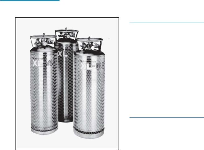
The XL-45, XL-50 and XL-55 are vacuum insulated, stainless steel containers designed to store and transport cryogenic liquid oxygen, nitrogen or argon. Built to DOT 4L standards, these containers may be used for over the road transportation of cryogenic fluids, as well as on-site storage and supply in a wide range of applications.
As rugged, long holding time, self-contained gas supply systems, these cylinders are capable of providing continuous flow rates of up to 350 cfh (9.2 cu.m/h) with a delivery pressure of approximately 100 psig (6.9 bar/690 kPa).
SPECIFICATIONS |
|
|
|
|
|
XL-45 |
XL-50 |
XL-55 |
|
|
|
|||
|
Dimensions |
|
|
|
|
Diameter |
20 in. (508 mm) |
20 in. (508 mm) |
20 in. (508 mm) |
|
Height |
61 ½ in. (1562 mm) |
64 5/8 in. (1641 mm) |
69 7/8 in. (1764 mm) |
|
Weight |
|
|
|
|
Empty (Nominal) |
255 lb. (116 kg) |
270 lb. (122 kg) |
270 lb. (122 kg) |
|
Capacity, Gross |
180 liters |
193 liters |
210 liters |
|
Capacity, Usable Liquid |
169 liters |
181 liters |
200 liters |
|
Weight on Contents Max. |
|
|
|
|
Based on DOT Rated Service Pressure |
|
|
|
|
Oxygen |
388 lb. (176 kg) |
416 lb. (189 kg) |
454 lb. (206 kg) |
|
Nitrogen |
273 lb. (124 kg) |
293 lb. (133 kg) |
319 lb. (145 kg) |
|
Argon |
471 lb. (214 kg) |
505 lb. (229 kg) |
551 lb. (250 kg) |
|
Normal Evaporation Rate* |
|
|
|
|
(% Capacity per Day) |
|
|
|
|
Oxygen/Argon |
1.2% |
1.1% |
1.1% |
|
Nitrogen |
1.9% |
1.8% |
1.7% |
|
Gas Flow Rate @ NTP (STP**) |
|
|
|
|
Oxygen, Nitrogen, Argon |
350 cfh (9.2 cu.m/h) |
350 cfh (9.2 cu.m/h) |
350 cfh (9.2 cu.m/h) |
|
Relief Valve Setting |
230 psig |
230 psig |
230 psig |
|
|
(16 bar/1586 kPa) |
(16 bar/1586 kPa) |
(16 bar/1586 kPa) |
|
Inner Container Bursting Disc |
380 psig |
380 psig |
380 psig |
|
|
(26 bar/2620 kPa) |
(26 bar/2620 kPa) |
(26 bar/2620 kPa) |
|
Dual Pressure Building/ |
|
|
|
|
Economizer Regulator*** |
|
|
|
|
Pressure Building Setting |
125 psig |
125 psig |
125 psig |
|
|
(8.6 bar/862 kPa) |
(8.6 bar/862 kPa) |
(8.6 bar/862 kPa) |
|
Economizer Setting |
145 psig |
145 psig |
145 psig |
|
|
(10 bar/1000 kPa) |
(10 bar/1000 kPa) |
(10 bar/1000 kPa) |
|
Design Specifications |
|
|
|
|
TC |
4LM |
4LM |
4LM |
|
DOT |
4L |
4L |
4L |
|
Gaseous Capacity |
|
|
|
|
Based on DOT Rated Service Pressure |
|
|
|
|
@ NTP (STP) |
|
|
|
|
Oxygen |
4688 cu. ft (123 cu.m) |
5025 cu.ft (132 cu.m) |
5484 cu.ft.(144 cu.m) |
|
Nitrogen |
3771 cu. ft (99 cu.m) |
4043 cu. ft(106 cu.m) |
4402 cu. ft(116 cu.m) |
|
Argon |
4558 cu. ft(120 cu. m) |
4884 cu. ft(128 cu. m) |
5331 cu. ft(140 cu.m) |
|
|
|
|
|
Specifications are subject to change without notice
*Vented N.E.R. based on Usable Liquid Capacity
**Container pressure at or above factory Dual Pressure Building/Economizer Regulator setting
***Regulator has a pressure delta of 20 psig (1.4 bar/138 kPa)
Handling the Container
The XL Series containers are very rugged liquid cylinders. All cryogenic liquid cylinders have an inner container and an outer container with an insulated vacuum space between them. Any abuse (dents, dropping, tip-over, etc.) can affect the integrity of the containers insulation system.
When fully loaded, the XL-55 in argon service will contain 551 lb. (250 kg) of product. While moving a full container, you may be handling 821 lb. (372 kg) and you should treat the load accordingly. The attachment points provided on the XL-45/50/55 will allow you to use a hand truck or a hoist to handle these loads properly. Do not attempt to move these cylinders by any other means. While moving the cylinder, the following precautions should be observed.
qNever lay the cylinder on its side. Always ship, operate and store the unit in a vertical or upright position.
qWhen loading or unloading the container from a truck, use a hand truck, lift gate, crane or parallel loading dock. Never attempt to manually lift the unit.
qTo move the container over rough surfaces, or to lift the container, attach an appropriated sling to the lifting points cut into the welded support posts, and use a portable lifting device that will handle the weight of the container and its contents.
XL-45, XL-50, XL-55
Containers
FREIGHT DAMAGE
PRECAUTIONS
ANY FREIGHT DAMAGE CLAIMS ARE YOUR RESPONSIBILITY. Cryogenic liquid containers are delivered to your carrier from Taylor-Wharton’s dock in new condition. When you receive our product you may expect it to be in that same condition. For your own protection, take time to visually inspect each shipment in the presence of the carrier’s agent before you accept delivery. If any damage is observed, make an appropriate notation on the freight bill. Then ask the driver to sign the notation before you receive the equipment. You should decline to accept containers that show damage which may affect serviceability.
OPERATION
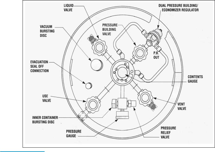
The XL-45 will store up to 169 liters of product, the XL-50 up to 181 liters and 200 liters for the XL-55. All three cylinders can deliver either liquid or gas. The following component and circuit descriptions are pertinent to the operation of all the containers and should be read before attempting operation. The components may be identified on the Component Location Illustration.
XL-45/50/55
Component
Locations
Internal Vaporizer – A liquid container for gas service must have an internal heat exchanger that functions as a gas vaporizer coil to convert liquid product to gas continuously during withdrawal. The XL-45/50/55 utilizes an internal heat exchanger that is inside the vacuum space attached to the container’s outer casing. It provides a means of introducing heat from outside the container’s insulated jacket, to vaporize liquid as gaseous product is withdrawn. The capacity of this circuit is sufficient to vaporize liquid as gaseous product is withdrawn. The capacity of this circuit is sufficient to vaporize product at flow rates up to 350 cfh @ NTP (9.2 cu. m/h @ STP). If a greater continuous demand is put on the vaporizer, an external vaporizer should be added to properly warm the gas and avoid malfunction, or damage, to gas regulators, hoses, and other downstream components.
Pressure Building – A Pressure Building circuit is used to ensure sufficient driving pressure during high withdrawal periods. This function is actuated by opening a hand valve that creates a path from the liquid in the bottom of the container, through the Pressure Building Regulator, to the gas space in the top. When the pressure building valve is open, and the container pressure is below the pressure building regulator setting, liquid taken from the

XL-45/XL-50-XL-55
Flow Diagram
inner container is vaporized in a heat exchanger which is inside the outer casing. The expanding gas is fed into the upper section of the container to build pressure. The resulting pressure will drive either the liquid or gas delivery system.
Pressure Building is not normally required unless container pressure drops below the gas output pressure desired. If, for example, the container pressure gauge reads 75 psig (5 bar/517 kPa), and your gas pressure requirement is 100 psig (6.9 bar/690 kPa), the pressure building valve may be opened to build container pressure to 125 psig (8.6 bar/862 kPa).
Economizer – An economizer circuit withdraws gas preferentially from the head space over the liquid in the container – gas that would otherwise be lost to venting. Excess pressure in the head space of the container is relieved by allowing gas to flow from this area directly to the USE valve outlet while gas is being withdrawn from the container; yet normal operating pressure is preserved to ensure uninterrupted product delivery. The economizer is automatic and requires no operator attention.
The USE Valve - This valve controls the gas outlet that allows product withdrawal through the internal vaporizer. It has the CGA connection that matches the gas service for which the container is configured.
The LIQUID Valve – Liquid product is added or withdrawn from the container through the connection controlled by this valve. It has the CGA fitting that is required for liquid line connections. The valve is open for fill or liquid withdrawal after connecting a transfer hose with compatible fittings to the LIQUID line connection.
NOTE:
The economizer and pressure building functions are controlled by a single dual action regulator. The pressure delta between the pressure building setpoint and the economizer setpoint is approximately 20 psig (1.4 bar/138 kPa). This delta cannot be altered.
RELIEF VALVES AND RECOMMENDED REGULATOR SETTINGS
Relief |
Pressure |
|
|
Normal |
|||
Valve |
Building |
Economizer |
Operating |
||||
Setting |
Setting |
Setting |
Range |
||||
22 |
psig |
N/A |
N/A |
0-22 |
psig |
||
1.5 |
bar |
N/A |
N/A |
0-1.5 |
bar |
||
152 |
kPa |
N/A |
N/A |
0-152 |
kPa |
||
230 |
psig |
125 |
psig |
145 |
psig |
75-175 |
psig |
16 |
bar |
8.6 |
bar |
10 |
bar |
5-12 |
bar |
1586 |
kPa |
862 kPa |
1000 kPa |
517-1207 |
kPa |
||
|
|
|
|
|
|
|
|
The PRESSURE BUILDING Valve – This valve isolates the liquid in the bottom of the container to the Dual Pressure Building/Economizer Regulator. This valve must be open to build pressure inside the container.

The VENT Valve – This valve controls a line into the head space of the container. It is used during the fill process. The VENT valve acts as a fill point during a pump transfer, or to vent the head space area while liquid is filling the inner container during a pressure transfer fill through the LIQUID valve.
The Pressure Gauge – The pressure gauge displays the internal container pressure in pounds-per-square-inch or in kilo Pascals.
Pressure
Building Rates
Graph
CAUTION:
When withdrawing gas from the cylinder, the capacity of the internal vaporizer can be exceeded. If gas is withdrawn at rates greater than the vaporizer capacity, liquid or very cold gas will be discharged. Severe damage to external equipment could result from the extreme cold.
The Full View Contents Gauge – The container contents gauge is a float type liquid level sensor that indicates container liquid through a magnetic coupling to a yellow indicator band. This gauge is an indication of approximate container contents only and should not be used for filling; liquid cylinders should be filled by weight.
Relief Devices – These cylinders have a gas service relief valve and inner container bursting disc with settings of 230 psig (16 bar/1586 kPa) and 380 psig (26 bar/2620 kPa) respectively. A 22 psig (1.5 bar/152 kPa) relief valve is available for liquid delivery applications.
WITHDRAWING GAS FROM THE CONTAINER
To withdraw gas from the XL-45/50/55 connect a suitable pressure regulator to the USE connection, and the output of the regulator to your external equipment. Then open the USE and the PRESSURE BUILDING valves. When the container pressure reaches 125 psig (8.6 bar/862 kPa), set the pressure regulator for the desired delivery pressure.
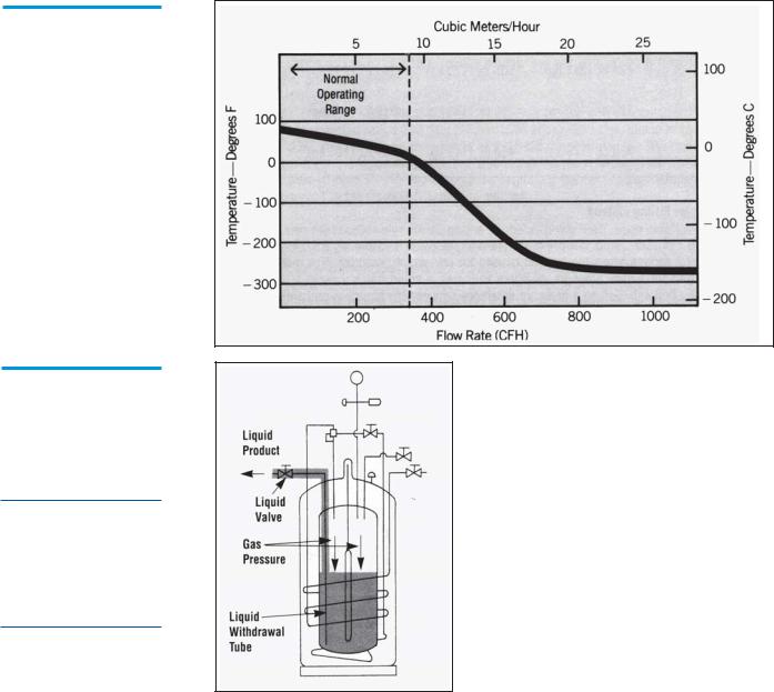
Vaporizer
Performance
Graph
Liquid
Withdrawal
CAUTION: To avoid
contamination, close the LIQUID valve on an empty container before disconnecting the transfer line.
Increasing Gas Supply Capacity – Two or more liquid containers may be manifolded together. Accessory manifolds are available for use in creating a higher capacity gas supply system. The XL-45/50/55 can supply gas at flow rates 1 up to 350 cfh @ NTP (9.2 cu.m/h @ STP) using only its internal vaporizer. At low flow rates, the gas supplied will be at near ambient temperature. As the flow demand is increased, the gas will become proportionately colder. If greater vaporizing capacity is required, an accessory external vaporizer is available. When an external vaporizer is used, it must be connected to the USE valve and the regulator moved to the output of the external vaporizer.
WITHDRAWING LIQUID FROM THE CONTAINER
Attach a transfer hose to the LIQUID connection and open the adjacent LIQUID valve. The pressure in the container will drive liquid product out through the valve as long as the container pressure exceeds that of the receiver.
The rate of liquid withdrawal from these containers is variable depending on the gas phase and the saturation temperature of the liquid.
FILLING THE CONTAINER
Cryogenic liquid containers must always be filled by weight to ensure there is enough gas head space (ullage) for liquid to expand as it warms. Using the procedure below, first determine the proper filled weight of each container. The weight derived is then used in either the Pump Transfer of Pressure Transfer filling procedures that follow.
 Loading...