


BT-320
OPERATING AND MAINTENANCE INSTRUCTIONS
10K, 24K, 38K
CRYOSTORAGE SYSTEMS WITH KRYOS CONTROLLER
REVIEW AND UNDERSTAND ALL SAFETY PROCEDURES IN FORM # tw-10 P/N 7950-8052 BEFORE ATTEMPTING TO INSTALL, OPERATE OR PERFORM MAINTENANCE ON THIS CRYOSTORAGE SYSTEM.
DO NOT ATTEMPT TO USE OR MAINTAIN THIS UNIT UNTIL YOU READ AND UNDERSTAND THESE INSTRUCTIONS. DO NOT PERMIT UNTRAINED PERSONS TO USE OR MAINTAIN THIS UNIT. IF YOU DO NOT FULLY UNDERSTAND THESE INSTRUCTIONS, CONTACT YOUR SUPPLIER FOR FURTHER INFORMATION.
Note:
For detailed information on the handling of cryogenic liquids, refer to the Compressed Gas Association publication: P-12 “Safe Handling of Cryogenic Liquids” available from the Compressed Gas Association Inc., 1235 Jefferson Davis Highway, Arlington, VA 2202.
Text Format Notation
In this owner’s manual we use some special text formats to denote certain portions of the system. These are listed below:
•Menu is indicated in ALL CAPS BOLD.
•Actual Menu Choices are indicated in ALL CAPS.
•Start Fill and Stop Fill sensor are indicated in ALL CAPS ITALICS.
•Specific Menu Descriptions under a main category are listed in Italics.
Safety
Liquefied Gases
Extremely cold refrigerant – Cover Eyes and Exposed Skin – Accidental contact of the skin or eyes with any cryogenic liquid or cold gas may cause a freezing injury similar to frostbite. Protect your eyes and cover your skin when handling stored product and when transferring liquid, or in any instance where the possibility of contact with liquid, cold pipes, and cold gas may exist. Safety goggles or a face shield should be worn when transferring liquid. Long-sleeved clothing and gloves that can be easily removed are recommended for skin protection. Cryogenic liquids are extremely cold and will be at a temperature of -196ºC (-320ºF) under normal atmospheric pressure.
Keep Equipment Well Ventilated – Although the liquefied gas refrigerant used in this equipment is non-toxic and non-flammable, it can cause asphyxiation in a confined area without adequate ventilation. An atmosphere that does not contain enough oxygen for breathing will cause dizziness, unconsciousness, or even death. These gases cannot be detected by the senses and will be inhaled normally as if they were air. Ensure there is adequate ventilation where this equipment is used and store liquid refrigerant supply containers only in a well ventilated area
Liquid Nitrogen System – The liquid nitrogen supply pressure at the inlet to the refrigerator should be in the range of 10 psig (0.7bar/69 kPa) to 20 psig (1l4bar/138 kPa) for optimum performance. Higher operating pressures will increase transfer losses and create excessive turbulence of the liquid in the refrigerator which can generate false signals to the liquid level controller causing the refrigerator to underfill. In “liquid phase” storage applications, excessive turbulence can cause splashing which could result in personal injury and/or damage to the refrigerator. When installing piping or fill hose assemblies, make certain a suitable safety relief valve is installed in each section of plumbing between shut-off valves. Trapped liquefied gas will expand greatly as it warms and may burst hoses or piping causing damage or personal injury. A relief valve is installed in the refrigerator plumbing to protect the line between the customer supplied shut-off valve and the refrigerator solenoid valve.
Warning: |
Inlet pressure should not exceed 22 psig (1.5bar/152 kPa). |
|
Higher pressures could result in damage to equipment and/or |
|
sufficient depletion of oxygen in the atmosphere to cause |
|
dizziness, unconsciousness, or death. |
Note:
Units are supplied with TaylorWharton approved controllers. If other liquid level controllers are used, please contact Taylor-Wharton before putting the refrigerator into service.
GENERAL INFORMATION
Electrical
Electrical Shock Can Kill – the liquid level controllers used with these refrigerators operate from 24VAC. However, the external transformer does have a 110/220VAC primary. Do not attempt any service on these units without disconnecting the electrical power cord.
Freight Damage Precautions
Any Freight damage claims are your responsibility. Cryostorage systems are delivered to your carrier from Taylor-Wharton’s dock in new condition. When you receive our product you may expect it to be in that same condition. For your own protection, take time to visually inspect each shipment in the presence of the carrier’s agent before you accept delivery. If any damage is observed, make an appropriate notation on the freight bill. Then, ask the driver to sign the notation before you receive the equipment. You should decline to accept containers that show damage which may affect serviceability.
Taylor-Wharton CryoStorage Systems are designed for applications where extremely low temperature storage of biological products is required. They are also appropriate for industrial or other applications where liquid nitrogen temperatures and high capacity are needed.
The 10K, 24K and 38K refrigerators covered by this publication are designed for, but not limited to, the laboratory environment. The 10K and 24K feature square, modular cabinets that facilitate grouping several units together in a cryostorage area. The 38K features a cylindrical stainless steel cryochamber. All of the models will accommodate inventory control systems or provide unobstructed storage area for larger product. All models are supplied with casters to enable limited mobility for cleaning purposes.
These standard models are equipped with the KRYOS electronic liquid level controller that will monitor and control the supply of liquid nitrogen to the unit. The controller features vacuum fluorescent display. The addition of a liquid nitrogen supply and inventory control racks for systematic retrieval of stored product completes the total cryostorage system.
Maximum Refrigerator Contents
Your cryostorage system has a maximum weight capacity which is stated in the specifications. This capacity exceeds the maximum amount of liquid nitrogen the refrigerator is capable of holding. Generally, as product is added to liquid phase storage, the stored product and inventory control system are heavier than the liquid nitrogen they displace. In vapor-phase storage applications, where the liquid refrigerant is found only in the bottom portion of the refrigerator, the weight of contents is determined more by the weight of the stored product.

CRYOSTORAGE SPECIFICATIONS
|
|
Liquid nitrogen at atmospheric pressure |
|||
|
|
||||
|
|
weighs 1.78 lb./liter (0.8 kg/liter). To |
|
||
|
|
ensure you are not exceeding the |
|
||
|
|
capacity of the cryostorage system, |
|
||
|
|
calculate the weight of the quantity of |
|
||
|
|
liquid nitrogen in your unit and subtract |
|||
|
|
the result from the Total Allowable |
|
||
|
|
Capacity Weight found in the specifica- |
|||
|
|
tions section of this publication. All |
|
||
|
|
Taylor-Wharton Gas Equipment |
|
||
|
|
Wharton cryostorage systems are |
|
||
|
|
designed to support the full weight of |
|
||
|
|
liquid nitrogen and a complete stainless |
|||
|
|
steel or aluminum inventory control |
|
||
|
|
system with boxes and specimens. |
|
||
Dimensions |
|
|
10K |
24K |
38K |
|
|
||||
|
|
|
|
|
|
Height1 |
|
in. |
44.0 |
44.0 |
49.0 |
|
|
mm |
1118 |
1118 |
1245 |
Width |
|
in. |
23.1 |
34.0 |
42.0 |
Depth2 |
|
mm |
587 |
864 |
1067 |
|
in. |
30.5 |
38.0 |
48.0 |
|
|
|
mm |
775 |
965 |
1219 |
Usable Height, Internal |
|
in. |
29.0 |
29.0 |
29.0 |
Internal Diameter3 |
|
mm |
737 |
737 |
737 |
|
in. |
21.0 |
31.0 |
39.0 |
|
Capacity |
|
mm |
533 |
787 |
991 |
|
|
|
|
|
|
Space Volume |
|
cu. ft |
5.8 |
12.7 |
20.0 |
LN2 Capacity |
|
cu. m |
0.16 |
0.36 |
0.56 |
|
L |
165 |
365 |
590 |
|
Evaporation Rate4 |
|
L/day |
5.0 |
7.0 |
8.0 |
Weight, Empty |
|
lb. |
245 |
405 |
565 |
|
|
kg |
111 |
184 |
256 |
Total Allowable Capacity Weight5 (including liquid |
|
lb. |
292 |
641 |
1008 |
refrigerant and stored product) |
|
kg |
133 |
291 |
457 |
|
|
||||
Maximum Gross Weight6 |
|
lb. |
540 |
1050 |
1575 |
|
|
kg |
245 |
476 |
715 |
Inventory Control System Specifications |
|
|
|
|
|
No 5 x 5 Racks7 |
|
|
7 |
17 |
28 |
No. Shelves/Rack |
|
|
13 |
13 |
13 |
No. 3.0 x 3.0 Racks8 |
|
|
4 |
6 |
6 |
No. Shelves/Rack |
|
|
13 |
13 |
13 |
Vial Capacity, 2 ml9 |
|
|
10400 |
24050 |
38350 |
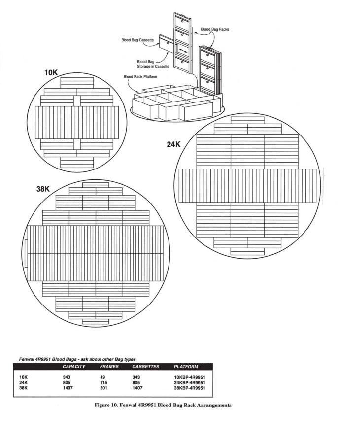
Blood Bag10 |
|
|
175 |
360 |
560 |
Straw Capacity11 |
|
|
44000 |
59400 |
114000 |
Footnotes:
1Maximum required clearance (with the lid open) for the 10K is 69 in. (1753 mm); 24K is 76 in (1930 mm); and 38K is 90 in. (2286 mm).
2Depth with lid open for 10K is 34 in (864 mm); 24K is 48.5 in. (1232 mm); 38K is 55 in. (1397 mm).
3Temperature Gradient Suppression System reduces internal diameter by approximately ¼ in. (6.4 mm). Does not apply to 10K.
4Evaporation rate is nominal. Actual rate may be affected by the nature of the contents, atmospheric conditions, container history, and manufacturing tolerances.
5Does not include the weight of the refrigerator itself. Refer to Maximum Refrigerator Contents section.
6Includes the empty weight and total allowable capacity weight.
75 in. x 5 in. (127 mm x 127 mm) 100 cell box.
83.0 in. x 3.0 in. (76 mm x 76 mm) 25 cell box.
92 ml vial size; 12.5 mm O.D. internal thread.
10Fenwall 4R-5461 bag.
110.5 cc straws, 10 per goblet, 2 13 mm goblets per cane; 2
KRYOS Specifications
Configurations: Designed exclusively for the Taylor-Wharton CryoStorage
Systems (10K, 24K and 38K
Power Supply: |
24VAC, 40 VA – Standard |
|
|
16.5 VAC, 40 VA with Battery Backup Option |
|
Sensor Assembly: |
4-Thermistor Assembly – Optional |
|
|
8-Thermistor Assembly – Optional |
|
|
Freeze-Guard Assembly – Standard |
|
Thermocouples: |
Operates with none, 1 or 2 Type T |
|
|
Thermocouples (1 piece standard) |
|
Solenoid Valve: |
24 VAC cryogenic solenoid valve – Standard |
|
Control Type: |
Liquid Level Control or Liquid Level Control with Tempera- |
|
|
ture Control |
|
Security: |
Keyless entry via 4-digit password |
|
|
Power On/Off Password |
|
|
Menu access Password |
|
Alarms: |
Activates an audible and a visual alarm. Description of the |
|
|
alarm condition displays on front panel. |
|
|
Activates remove alarm after user defined delay |
|
Diagnostics: |
Circuit diagnostics at start-up |
|
|
Sensor diagnostics from front panel |
|
|
Thermocouple diagnostics from front panel |
|
|
Manual Test for audible, visual and remote alarms |
|
Temp. Calibration: |
Automated calibration from the front panel |
|
Communications: |
RS-232 Serial Port for 2-way communications capable |
|
Logging Capacity: |
System Logs |
(4096 events) |
|
Alarm Logs |
(4096 events) |
|
Temperature Logs |
(32,768 events) |
Battery: |
A CR2032 coin cell battery is used to back up time/date |
|
INSTALLATION
Unpacking and Inspection
Inspect shipping containers for external damage. All claims for damage (apparent or concealed) or partial loss of shipment must be made in writing within five (5) days from receipt of goods. If damage or loss is apparent, please notify the shipping agent immediately.
Open the shipping containers; a packing list is included with the system to simplify checking that all components, cables, accessories, and manuals were received.
Please use the packing list to check off each item as the system is unpacked. Inspect for damage. Be sure to inventory all components supplied before discarding any shipping materials. If there is damage to the system during transit, be sure to file proper claims promptly with the carrier and insurance company. Please advise Taylor-Wharton of such filings. In case of parts or accessory shortages, advise Taylor-Wharton immediately. Taylor-Wharton cannot be responsible for any missing parts unless notified within 60 days of shipment.
Repackaging for Shipment
If it is necessary to return any part of the system for repair or replacement, a Material Return Authorization (MRA) number must be obtained from an authorized factory representative before returning the instrument to our service department. Contact your distributor for return authorization.
When returning an instrument for service, the following information must be provided before obtaining an MRA:
A.System model and serial number, and controller serial number
B.B. User’s name, company, address, and phone number
C.Malfunction symptoms
D.Description of System
E.Material Return Authorization (MRA) number
If possible, the original packing material should be retained for reshipment. If not available, consult Taylor-Wharton for shipping and packing instructions. It is the responsibility of the shipper to assure that the goods are adequately packaged for return to the factory.
Liquid Nitrogen Supply Connection
The package included with the refrigerator includes a filter and an elbow. The liquid fill hose from a low pressure source of liquid nitrogen must be connected to the inlet through these two fittings. This liquid nitrogen source must have a shut-off valve, and may be any portable liquid cylinder or a bulk supply. The liquid nitrogen supply pressure at the inlet to the refrigerator should be in the range of 10 psig (0.7 bar/69 kPa) to 20 psig (1.4 bar/38 kPa) for optimum performance. Higher operating pressures will increase transfer losses and create excessive turbulence of the liquid in the refrigerator which can generate false signals to the liquid level controller causing the refrigerator to underfill. In “liquid phase” storage applications, excessive turbulence can cause splashing which could result in person injury and/or damage to the refrigerator.
If the liquid nitrogen supply pressure at the inlet to the refrigerator rises above the opening pressure of the relief valve on the refrigerator, liquid nitrogen will be discharged into the surrounding area which can cause a rapid and very dangerous depletion of oxygen in the atmosphere. Once this pressure relief device has opened and cooled to liquid nitrogen temperature, it will not reseat until it has warmed to near ambient temperature. THIS COULD PERMIT THE ENTIRE CONTENTS OF THE LIQUID NITROGEN SUPPLY SYSTEM TO BE DISCHARGED INTO THE IMMEDIATE AREA OF THE REFRIGERATOR(S).
WARNING: |
In order to prevent the relief device on the nitrogen refrigerator(s) |

from opening when the system is in operation, the liquid nitrogen supply system must be protected
by a pressure relief device that will open when the pressure at the inlet to the refrigerator(s) is approximately 22 psig (1.5 bar/152 kPa). Never install the supply system pressure relief device onto a liquid service line.
Installation
KRYOS Control Field Installation
1.Unplug power from old unit
2.Close liquid nitrogen supply at valve
3.Remove 4 phillips head screws from controller face escutcheon
4.Remove 4 phillips head screws from cabinet top and 2 from old control
5.Withdraw old controller from cabinet top, noting how the controller body has been resting in guide slots
6.Unplug all jacks and wires from old controller and set aside
7.Remove 4 phillips head screws from real electrical panel
8.Unplug all connectors and wires and set panel aside
9.Remove rear plumbing access panel
10.Disconnect supply hose from solenoid valve using a 7/8 inch wrench
11. |
Remove old solenoid |
Qty |
Description |
K-Series |
|
- two ¼ inch hex head screws |
10, 24 |
||
|
- one compression fitting1using 3/8Cointrolch wrePanelches |
5140-1166 |
||
12. |
Lower lid and lock hinged lid1 to cabinet24VACtop Wall Transformer |
R08K-9C04 |
||
13. |
Raise hinged lid. Cabinet top1 shouldThermocouplealso raise out–ofTempthe waySensor |
R08K-9C51 |
||
14. |
Remove all wire and electrical1 |
componentsPlumbingother than sensors and thermo- |
R10K-8C64-R |
|
|
couple |
1 |
Lid Switch |
5160-1042 |
15. |
|
1 |
Sensor Assembly |
|
Remove old sensor tube with sensors• left in place |
5140-1163 |
|||
16. |
Mark old sensor locations with electricalFreezetape -Guard Capable |
|||
17.Measure and made note of the “Start•Fill”,Sensor“Stop-TFill” and temperature sensors5140-1161 from the bottom of the sensor tube.•You8willThermistorneed this(option)information to set up the5140-1164
•4 Thermistor (option) 5140-1162new controller.
1 |
Wiring Harness w/Electric Panel |
5140-1167 |
18. Reverse procedure to install KRYOS control. |
R06K-8C20 |
|
1 |
Remote Alarm Plug |
|
1 |
Operating Instructions |
7950-8320 |
1 |
Sensor Tube-Perf. S. Steel |
R23K-9C96 |
1 |
Inlet Filter |
7631-1075 |
INTRODUCTION
WARNING
INLET PRESSURE MUST NOT EXCEED 22 PSIG (1.5 BARL
HIGHER PRESSURES COULD RESULT IN DAMAGE
TO EQUIPMENT AND/OR SUFFICENT DEPETION
OF OXYBEN IN THE ATMOSPERE TO CAUSE
DIZZINESS, UNCONSCIOUSNESS OR EVEN DEATH.
DO NOT REMOVE THIS LABEL
DECAL PART NO. R23K-9C42
Figure 2. Warning Label (R23K-9C42
Filling the Refrigerator (Initial Fill)
The 10K and 24K units using the KRYOS controller come preset from the factory to operate. For the 38K unit, refer to the Installing the Controller section in this manual.
The liquid nitrogen supply pressure at the inlet to the refrigerator should be in the range of 10 psig (0.7 bar/69 kPa) to 20 psig (1.4 bar/138 kPa) for optimum performance. Higher operating pressures will increase transfer losses and create excessive turbulence of the liquid in the refrigerator which can generate false signals to the liquid level controller causing the refrigerator to underfill. In “liquid phase” storage applications, excessive turbulence can cause splashing which could result in personal injury and/or damage to the refrigerator.
WARNING: Maintain adequate ventilation to prevent asphyxiation hazard (see Safety Precautions)
Power Supply Connection
Connect the 24 Volt AC power supply to the rear of the cryostorage system; then plug the power supply into a surge protected 110/120 VAC outlet.
WARNING: If the fill fails to stop for any reason, quickly close the liquid supply valve to prevent overfilling until the cause of the problem can be determined.
Thank you for purchasing this product. This state of the art CRYOSTORAGE SYSTEM can control either the liquid level and/or the vapor temperature range. The features are designed to provide a safe environment for samples while at the same time tracking all relevant information associated with the freezer. This control provides a complete historical record of the environment in your freezer and therefore, the environment in which your samples have been stored.
CONTROL COMPONENTS
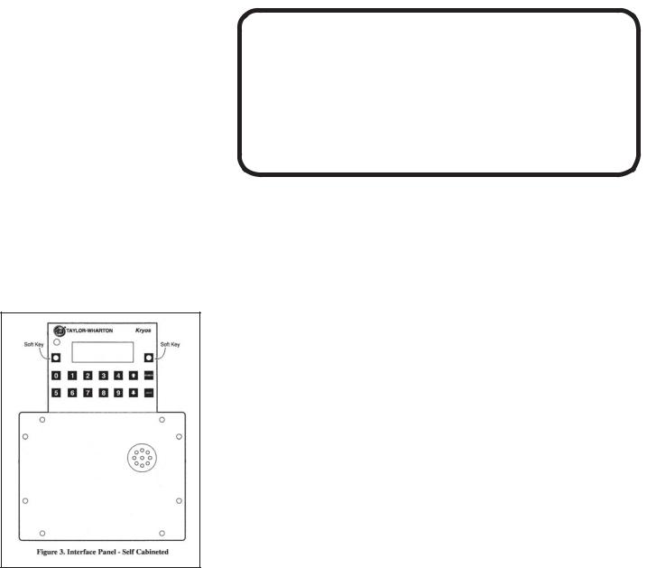
Interface Panel
The KRYOS Interface panel, which the user will interact with, contains the vacuum fluorescent display as well as the number keypad, power button, help button and the soft-key control buttons.
Main Control
The “brain” for the control system “talks” to the interface unit and makes all decisions regarding liquid levels, temperatures, valve opening/closing, etc. It is either housed in a separate box, or located away from the Interface Panel.
Sensor Assembly
A standard 7+1 thermistor assembly, includes the Freeze-Guard over-fill sensor. Optional 4 thermistor, or 8 thermistor sensor assembly can be ordered. The 4 thermistor assembly maintains the liquid level between 2 middle sensors. The 8 thermistor assembly maintains the liquid level between the high sensor and the low sensor assigned by the user. The standard 7 thermistor assembly is similar to an 8 sensor assembly in that the user can select the START FILL and STOP FILL positions. The eighth position on this assembly is tied into an inline plumbing thermistor, which detects if the solenoid valve fails to close.
Lid Switch
Is attached to the hinge and determines whether or not the lid is open on the freezer. This also allows the control to determine whether to active the Quickchill
or Auto Defog features.
Solenoid Valve
Is designed to work with 24 VAC solenoid valves manufactured by Valcor, ParkerHannifin, ASCO or Alcon.
Thermocouples
Type T thermocouples determine the temperature in the freezer. The user may choose to use NONE, 1 or 2 thermocouples with this control at any time.
Wall Transformer
A 24 VAC, 40 VA wall transformer is required. The system is supplied with a transformer compatible with common household (North American) 110VAC. These wall transformers have UL approval. UL approval for the system as a whole is not required since the control operates on such a low voltage. If your power source differs, or is subject to disruption or line surges due to other equipment on line, consult your Taylor-Wharton representative.
Remote Alarm
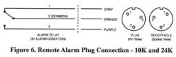
If an error condition occurs for a user defined period of time a remote alarm circuit can be initiated. This is accomplished by connecting a remote device to the remote alarm jack on the rear electrical panel. The 3-pin jack on the back of the unit provides continuity between pin #2 (common) and pin #1 in the normal condition. Continuity between pin #2 and pin #3 is provided in an error condition (See Figure 6).
OPERATION |
Operating Parameters |
||
|
|
When materials are immersed in liquid nitrogen, they will assume the temperature of |
|
|
|
the liquid -196ºC (-320ºF). When material is stored in the vapor phase over the liquid, |
|
|
|
the liquid nitrogen is still a very cold refrigerant, but the refrigerator’s interior tempera- |
|
|
|
ture increases somewhat as product is stored higher over the liquid. This temperature |
|
|
|
differential is not significant in many biological storage applications, and is affected by |
|
|
|
the amount of product stored in the refrigerator, the type and size of inventory control |
|
|
|
system, and the liquid level in the unit. |
|
|
|
The liquid level in the refrigerator is determined by the position of the sensor probes |
|
|
|
in the tube located at the front of the refrigerator. These probes are set at installation |
|
|
|
to maintain a specific liquid level. The controller operates a fill cycle that adds liquid at |
|
|
|
a low level, fills to a predetermined high level, then stops the fill (See Figure 5). The |
|
|
|
cycle repeats when the liquid level drops to the low level sensor over time. Sensor |
|
|
|
probe assignments may be changed on the controller keypad to define new high and |
|
|
|
low levels, and these levels may be set independently to vary the liquid level differen- |
|
|
|
tial between fills. Prior to the initial fill of the refrigerator, a determination should be |
|
|
|
made whether vapor phase or liquid phase storage will be utilized. |
|
|
|
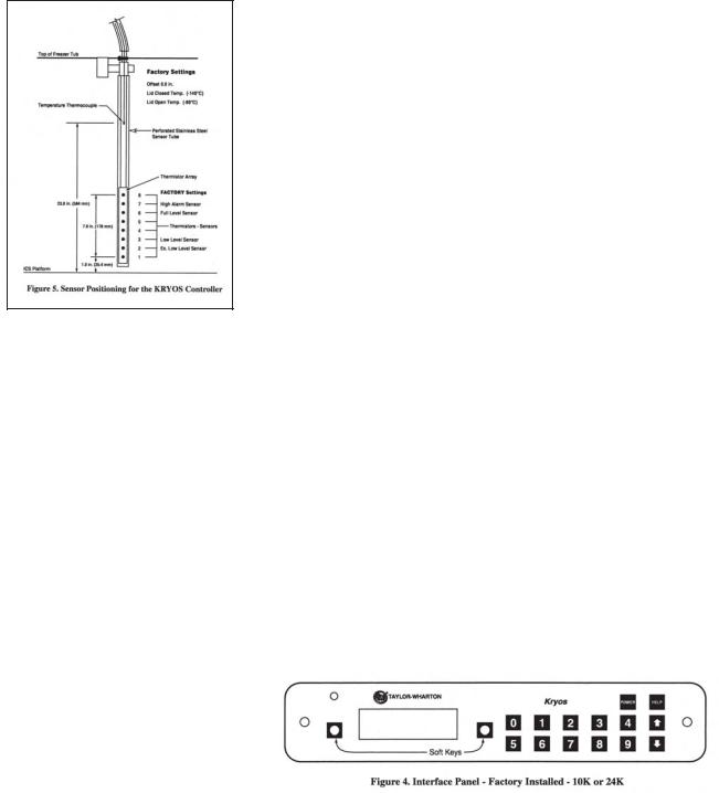
The sensor probe contains seven thermistors that can be preprogrammed for any |
|
|
|
liquid level application. The separate sensor in the sensor tube is the temperature |
|
|
|
thermocouple. The thermocouple is normally positioned above the High Alarm sensor |
|
|
|
to measure the warmest condition in the storage chamber. The factory sensor posi- |
|
|
|
tions will maintain a liquid level between 3 in. (76 mm) to 6 in. (152 mm). The dimen- |
|
|
|
sions used for the factory sensor installation are shown in Figure 5. |
|
|
|
Liquid Phase Storage |
|
|
|
Liquid phase storage is normally utilized when liquid nitrogen temperatures are |
|
|
|
required to maintain stored product viability and the storage medium is adequate for |
|
|
|
storage in liquid nitrogen. |
|
|
|
In a typical liquid phase storage system, the liquid level sensors are positioned to |
|
|
|
maintain the liquid level at or below the top level of the inventory control system. |
|
|
|
During operation, the upper levels of the inventory control system will at times be- |
|
|
|
come exposed as the liquid level fluctuates. |
|
|
|
Care must be taken to ensure that the liquid level remains below the bottom of the |
|
|
|
refrigerator lid. Exposure to liquid nitrogen may result in physical damage to the lid. |
|
|
|
Additionally, operating the refrigerator with high liquid levels characteristic of liquid |
|
|
|
phase storage may result in turbulence during fill cycles. Caution must be exercised if |
|
|
|
the refrigerator lid is opened during a fill, and appropriate safety equipment should |
|
|
|
always be worn. |
|
|
|
|
Thermocouple Positioning |
|
|
|
The thermocouple is a separate sensor designed in conjunction with the |
|
|
|
|
|
|
|
controller temperature readout to monitor and control the temperature |
|
|
|
within the refrigerator. The termocouple should be positioned about the |
|
|
|
High Level Alarm sensor. |
|
|
|
|
NOTE:
Temperature Gradient Suppression Systems are specifically designed for use in vapor phase applications and will be of little value when liquid phase storage is used.
Temperature Gradient Suppression System
Most Taylor-Wharton CryoStorage units include a Temperature Gradient Suppression System. The Temperature Gradient Suppression System is a thermal conductor designed to conduct heat downward toward the nitrogen reservoir, and by doing so, will significantly reduce the temperature gradient between the top of the inventory control system and the nitrogen reservoir.
While specific temperature profiles will vary with the use of the refrigerator and the type of inventory control system used, the Temperature Gradient Suppression System is an effective way to lower the temperature underneath the refrigerator lid without noticeably increasing liquid nitrogen consumption.
The chart below represents typical temperature gradients within a Taylor-Wharton CryoStorage System utilizing the Temperature Gradient Suppression System.
Adding an Inventory Control System
The purpose of the inventory control system is to bring order to the storage of many small samples, and to allow direct retrieval of the particular sample you need at any time. It is important to be aware that when you lift an ICS rack from the refrigerator it is in a warmer environment. Learn to locate your sample quickly to avoid unnecessary warming of your stored product.
Keep ICS inserts (drawers or boxes) and dividers in good repair. Replacement inserts and dividers are available from your Taylor-Wharton distributor to keep your system as efficient as possible.
Always wear gloves when handling ICS racks or stored product, as they are very cold
– read the precautions in the Safety section of these instructions, and in TaylorWharton publication TW-10 “Handle With Care”, for more detail on handling product stored in liquid nitrogen.

When removing ICS racks to retrieve product, protect the labels, plastic, and electronic areas of the refrigerator from liquid nitrogen that may spill from the rack inserts. These parts of the refrigerator are subject to damage from the extreme low temperature of the refrigerant.
If an alternate platform is supplied with your inventory control system, the liquid phase platform in the bottom of your refrigerator may need to be removed to accommodate your inventory control system platform.
Fully removing Inventory Control System racks such that frost forms on them, and then setting this frost, along with the racks back into the freezer, will deposit the frost in the bottom of the freezer. Do not let ice or debris collect in the bottom of the freezer. Schedule periodic clean out if racks no longer stand upright.

 Loading...