


TW-72
Instructions for
XL-160 and XL-180
Do not attempt to use or maintain this unit until you read and understand these instructions. Do not permit untrained persons to use or maintain this unit. If you do not fully understand these instructions, contact your supplier for further information.

Contents
Container Safety |
....................................................................... |
1 |
General Information .................................................................. |
2 |
|
Specifications ............................................................................ |
|
2 |
Operation................................................................................... |
|
4 |
Component Descriptions ............................................. |
4 |
|
Withdraw Liquid from the Container ........................... |
5 |
|
Filling the Container .................................................... |
5 |
|
Fill Hose Kits ............................................................... |
6 |
|
Maintenance .............................................................................. |
|
8 |
Checking Container Performance ................................ |
8 |
|
Hand Valve Repair ....................................................... |
9 |
|
Shock Mount Foot Ring .............................................. |
9 |
|
Full View Contents Gauge Maintenance ...................... |
10 |
|
Troubleshooting ........................................................................ |
|
13 |
Replacement Parts .................................................................... |
14 |
|
Accessories |
14 |
|

Pressure Hazard – The containers covered by this literature contain liquefied gas under pressure. Sudden release of this pressure may cause personal injury by issuing cold gas or liquid, or by expelling parts during servicing. Do not attempt any repairs on these containers until all pressure is released, and the contents have been allowed to vaporize to ensure no pressure buildup can occur.
Extreme Cold – Cover Eyes and Exposed Skin – Accidental contact of the skin or eyes with any cryogenic liquid or cold issuing gas may cause a freezing injury similar to frostbite. Protect your eyes and cover your skin when handling the container or transferring liquid, or in any instance where the possibility of contact with liquid, cold pipes, and cold gas may exist. Safety goggles or a face shield should be worn when withdrawing liquid or gas. Long-sleeved clothing and gloves that can be easily removed are recommended for skin protection. Cryogenic liquid is extremely cold and will be at temperatures below -300° F (-184°C) under normal atmospheric pressure.
Keep Equipment Well Ventilated – Although the gases used in these containers are non-toxic and non-flammable, they can cause asphyxiation in a confined area without adequate ventilation. An atmosphere that does not contain enough oxygen for breathing can cause dizziness, unconsciousness, or even death. These gases cannot be detected by the human senses and will be inhaled normally as if they were air. Ensure there is adequate ventilation where these gases are used and store liquid containers outdoors or only in a well ventilated area.
Replacement Parts Must be Clean to Prevent Contamination – Use only TaylorWharton recommended spare parts, and be certain parts used are properly cleaned to prevent contamination of stored product. For information on cleaning, consult the Compressed Gas Association (CGA) pamphlet1 G-4.1, “Cleaning for Oxygen Service” or equivalent industrial cleaning specifications.
Install Relief Valves in Cryogenic Liquid Lines – When installing or fill hose assemblies, make certain a suitable safety relief valves is installed in each section of plumbing between shut-off valves. Trapped liquefied gas will expand as it warms and may burst hoses or piping causing damage or personal injury.
Container
Safety
NOTE:
For detailed information on teh handling of cryogenic liquids, refer to the Compressed Gas Association publication(1): P-12 “Safe Handling of Cryogenic Liquids.”
1 Available from the Compress Gas Association, 1235 Jefferson Davis Highway, Arlington, VA 22202.

General
Information
Specifications
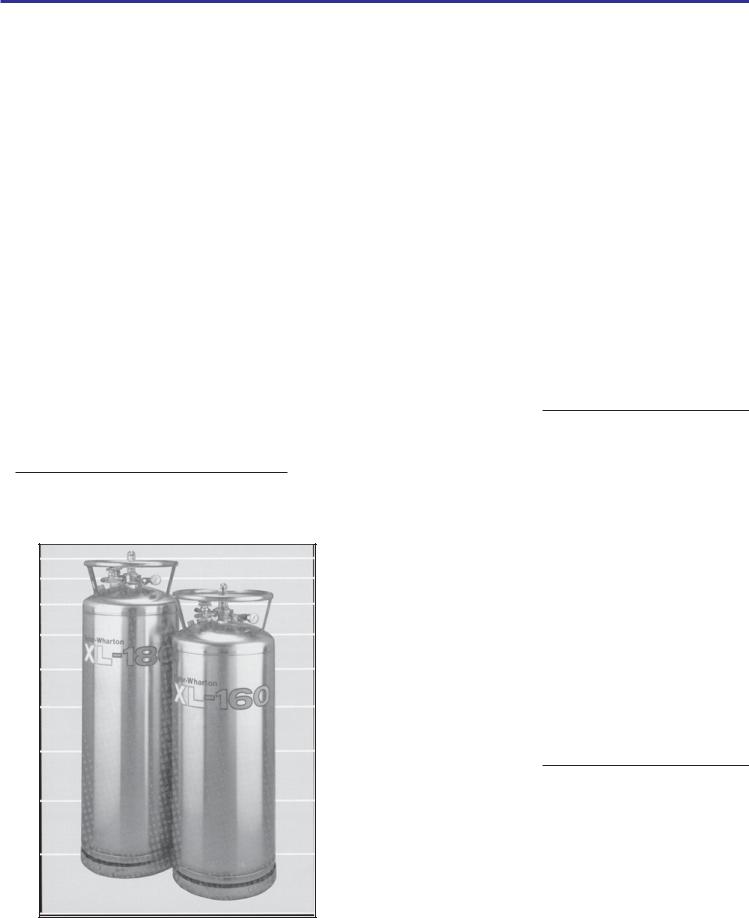
The XL-160 and XL-180 are vacuum insulated, stainless steel containers designed to store, transport, and dispense cryogenic liquid nitrogen. Built to DOT 4L standards, these containers may be used for over-the-road transportation, as well as on-site storage and supply.
|
XL-160 |
XL-180 |
Dimensions (Nominal) |
|
|
Diameter |
20 in. (508 mm) |
20 in. (508 mm) |
Height |
57 5/8 (1464 mm) |
64 3/8 in. (1635 mm) |
|
|
|
Weight |
|
|
Empty |
197 lb. (89 kg) |
205 lb. (93 kg) |
|
|
|
Approximate Weight of Contents |
|
|
(Nitrogen) in 22 psig (1.5 bar/152 |
|
|
kPa) Service |
259 lb. (117 kg) |
296 lb. (134 kg) |
|
||
|
|
|
Capacity, Gross |
163 liters |
186 liters |
|
|
|
Capacity, Useable Liquid |
160 liters |
180 liters |
|
|
|
Normal Evaporation Rate* (% |
|
|
Capacity per Day) |
|
|
Nitrogen |
1.3% |
1.25% |
|
|
|
Relief Valve Setting |
22 psig |
22 psig |
|
(1.5 bar/152 kPa) |
(12 bar/1214 kPa) |
|
|
|
Inner Container Bursting Disc |
176 psig |
176 psig |
|
(12 bar/ 1214 kPa) |
(12 bar/1214 kPa) |
|
|
|
Design Specifications |
|
|
T/DOT |
4LM/4L |
4LM/4L |
Rated Service Pressure |
100 psig |
100 psig |
|
(6.9 bar/ 690 kPa) |
(6.9 bar/690 kPa) |
Specifications are subject to change without notice. *Vented N.E.R. based on Useable Liquid Capacity
Handling the Container
XL Series containers are very rugged liquid cylinders. All cryogenic liquid containers have an inner container and on outer container with an insulated vacuum space between them; any abuse (dents, dropping, tip-over, etc.) can affect the integrity of the container’s insulation system.
When fully loaded, the XL-180 in nitrogen service will contain up to 296 lb. (134 kg) of product. While moving a full container, you may be handling up to 501 lb. (227 kg), and you should treat the load accordingly. The attachment points provided on the Xl- 160/XL-180 will allow you to use a hand truck, or a hoist, to handle these loads properly. Do not attempt to move these cylinders by any other means. When moving the cylinder, the following precautions should be observed:
Never lay the container on its side. Always ship, operate, and store the unit in a vertical or upright position.
When loading or unloading the container from a truck, use a lift gate, a crane, or a parallel loading dock. Never attempt to manually lift from the unit.
To move the container over rough surfaces or to life the container, attach an appropriate sling to the lifting points cut into the welded support posts, and use a portable lifting device that will handle the weight of the container.
XL-160 and XL-180 Liquid Cylinders
Freight Damage Precautions
Any Freight Damage claims are your responsibility. Cryogenic liquid containers are delivered to your carrier from Taylor-Wharton’s dock in new condition. When you receive our product you may expect it to be in that same condition. For your own protection, take time to visually inspect each shipment in the presence of the carrier’s agent before you accept delivery. If any damage is observed, make an appropriate notation on the freight bill. Then ask the driver to sign the notation before you receive the equipment. You should decline to accept containers that show damage which may affect service ability.

Operation
The model numbers of XL-160/XL-180 indicate their respective liquid storage capacities in liters of product. Both cylinders are designed for liquid nitrogen service only. The following component and circuit descriptions are pertinent to either container and should be read before attempting operation. The components may be identified on the Component Location illustration.
XL-160/XL-180 Component Locations
The Liquid Valve - Liquid product is added or withdrawn from the container through the connection controlled by this valve. It has the CGA fitting that is required for liquid connections.. The valve is opened for fill or liquid withdrawl after connecting a transfer hose with compatible fittings to the LIQUID line connection.
The Pressure Gauge - Thepressure gauge dsplays teh internal container pressure in pounds per-square-inch, bar or in kiloPascals.
The VENT Valve - This valve controls a line into the head space of the container. It is used during thet fill process. the VENT valve is opened to vent the head space area while liquid is entering the inner container during a pressure transfer fill through the LIQUID valve.
The Full View Contents Gauge - The container contents gauge is a float type liquid level sensor that indicates container liquid content through a magnetic coupling to a yellow indicator band. This gauge is an indication of approximate container contents only and should not be used for filling.
Relief Devices - These cylinders have inner container relief valves set at 22 psig (1.5 bar/152kPa) and inner container bursting disc that will rupture at 176 psig (12 bar/1213)
XL-160/XL-180 Flow Diagram
 Loading...