


KRYOS
®


KRYOS
TABLE OF CONTENTS
SAFETY PRECAUTIONS FOR LIQUID NITROGEN ........................................... 3
Extreme Cold - Cover Eyes and Exposed Skin ........................................................3
Keep Equipment Area Well Ventilated ...................................................................3
Liquid Nitrogen System .......................................................................................... 3
Electrical .................................................................................................................3
GENERAL INFORMATION ............................................................................ 4
Text Format Notation .............................................................................................4
KRYOS Specifications ..............................................................................................5
DELIVERY AND RETURNS.............................................................................. 6
Unpacking and Inspection ......................................................................................6
Freight Damage Procedures ..................................................................................6
Repackaging for Shipment ..................................................................................... 6
INSTALLATION ............................................................................................. 7
Getting Unit into Service ........................................................................................ 7
Electrical ................................................................................................................7
Power Supply Connection ..................................................................................... 7
OPERATION ................................................................................................. 7
Initial Fill ................................................................................................................7
Control Components ..............................................................................................7
Operating Parameters .........................................................................................10
Liquid Phase Storage ............................................................................................10
Thermocouple Positioning .................................................................................... 11
CONTROLLER OPERATION ......................................................................... 12
Introduction .........................................................................................................12
Normal Fill Cycle .................................................................................................12
Power ................................................................................................................... 12
Main Display Screen ............................................................................................12
The Menu System .................................................................................................13
Temperature Thermocouple Select ....................................................................... 15
Calibrate Temperature ......................................................................................... 15
Test Temperature System ....................................................................................... 15
Level Sensing .......................................................................................................15
Test Level Sensors .................................................................................................16
Alarms and Error Conditions ...............................................................................16
System Alarms ......................................................................................................16
Test Alarms ..........................................................................................................17
Logging ................................................................................................................17
Dump Logs ............................................................................................................ 18
Error Logs .............................................................................................................18
System Logs ..........................................................................................................19
Temperature Logs ................................................................................................19
Erase Logs ............................................................................................................. 19
Security ................................................................................................................19
User Options ........................................................................................................19
Lid Switch Setup ....................................................................................................20
Manual Defog .......................................................................................................20
Auto Defog ........................................................................................................... 20
Quick-Chill ............................................................................................................ 20
Control By Temperature ........................................................................................20
Temperature Control Settings ............................................................................... 20
Control Temperature ............................................................................................20

KRYOS
Menu Password ...................................................................................................20
Serial Communications and RS-232 Settings......................................................... 21
Time and Date Set ................................................................................................. 21
User Access Logs ...................................................................................................21
Control Range .......................................................................................................21
Freeze-Guard Options ......................................................................................... 21
Valve Monitoring .................................................................................................22
Valve Open Duration ............................................................................................22
Valve De-Icing ......................................................................................................22
Splash-Guard .......................................................................................................22
Display Brightness ................................................................................................22
About this Control ................................................................................................22
Control On Battery Back-up Version .................................................................... 22
Differences Between the Regular KRYOS and the Battery Backed KRYOS.............23
Operation ............................................................................................................23
Battery Life ...........................................................................................................24
INTERFACE SOFTWARE ............................................................................. 24
Making Adjustments to the KRYOS Sensor Assembly ........................................... 24
Version 9.22 Level Reading ...................................................................................25
Recommendations for Liquid Storage ..................................................................25
Removing/Installing the Solenoid Valve ...............................................................27
Controller Electrical Tests ...................................................................................... 27
Sensor Plug Schematic ..........................................................................................28
Plumbing Assembly ...............................................................................................29
TROUBLESHOOTING .................................................................................. 30
Symptoms ............................................................................................................. 30
Controller Will Not Turn ON ................................................................................30
Indicates High Liquid Level .................................................................................. 31
Indicates Low LN
2
Supply ...................................................................................... 32
Indicates Open Sensor .......................................................................................... 32
Temperature Reading 10 to 20 Degrees Warm .....................................................32
Fill Solenoid Cycles On and Off ............................................................................ 33
Fill Solenoid Makes Humming Noise.....................................................................33
Transformer Makes Humming Noise .....................................................................33
Display = “Check” ...............................................................................................33
Lid Open Alarm ....................................................................................................33
QCF (Quick Chill Feature) Will Not Operate .......................................................33
Defog Feature Will Not Operate .......................................................................... 34
Push Buttons Will Not Respond ............................................................................ 34
Liquid Level Readout is Incorrect .........................................................................34
Power Failure Alarm ............................................................................................ 34
REPLACEMENT KRYOS CONTROLLER FIELD INSTALLATION ........................ 35
For all LABS and 38K Cryostorage Units ............................................................... 35
For 10K and 24K Cryostorage Units .....................................................................35
Factory Settings ...................................................................................................36
REPLACEMENT PARTS ................................................................................ 36
SERVICE AND MAINTENANCE HISTORY LOG ............................................. 37
TABLE OF CONTENTS (continued...)

3
KRYOS
SAFETY PRECAUTIONS FOR LIQUID
NITROGEN
Nitrogen is an inert, colorless, odorless, and tasteless gas making up four-fifths of
the air you breathe – and can be very dangerous. Air is roughly one-fifth oxygen.
Liquid nitrogen is at a temperature of -196°C (-320°F) under normal atmospheric
pressure.
Extreme Cold - Cover Eyes and Exposed Skin
Accidental contact of liquid nitrogen or cold issuing gas with the skin or eyes may
cause a freezing injury similar to frostbite. Handle the liquid so that it won’t splash
or spill. Protect your eyes and cover the skin where the possibility of contact with the
liquid, cold pipes and cold equipment, or cold gas exists. Safety goggles or a face
shield should be worn when operating this equipment. Insulated gloves that can be
easily removed and long sleeves are recommended for arm protection. Trousers
without cuffs should be worn outside boots or over the shoes to shed spilled liquid.
Keep Equipment Area Well Ventilated
Although nitrogen is non-toxic and non-flammable, it can cause asphyxiation in
a confined area without adequate ventilation. Any atmosphere not containing
enough oxygen for breathing can cause dizziness, unconsciousness, or even death.
Nitrogen, a colorless, odorless, and tasteless gas, that cannot be detected by the
human senses and will be inhaled normally as if it were air. Without adequate
ventilation, the expanding nitrogen will displace the normal air resulting in death.
Liquid Nitrogen System
The liquid nitrogen supply pressure at the inlet to the refrigerator should be in
the range of 10 psig (0.7 bar/69 kPa) to 20 psig (1.4 bar/138 kPa) for optimum
performance. Higher operating pressures will increase transfer losses and create
excessive turbulence of the liquid in the refrigerator which can generate false signals
to the liquid level controller causing the refrigerator to under-fill. In “liquid phase”
storage applications, excessive turbulence can cause splashing which could result in
personal injury and/or damage to the refrigerator. When installing piping or fill hose
assemblies, make certain a suitable safety relief valve is installed in each section of
plumbing between shut-off and solenoid valves. Trapped liquefied gas will expand
greatly as it warms and may burst hoses or piping causing damage or personal
injury. A relief valve is installed in the refrigerator plumbing to protect the line
between the customer supplied shut-off valve and the refrigerator solenoid valve.
Electrical
The liquid level controllers used with these refrigerators operate from 24/16.5 VAC.
However, the external transformer does have a 110/220 VAC primary. Disconnect
the electrical power cord from the outlet before attempting any service.
For more detailed information concerning safety precautions and safe practices
to be observed when handling cryogenic liquids consult CGA pamphlet P-12
“Handling Cryogenic Liquids” available from the Compressed Gas Association,
1235 Jefferson Davis Highway, Arlington, VA 22202.
WARNING:
The following safety
precautions are for
your protection.
Before installing,
operating, or
maintaining this unit
read and follow all
safety precautions
in this section
and in reference
publications. Failure
to observe all safety
precautions can
result in property
damage, personal
injury, or possibly
death.
Caution:
When installing field
fabricated piping,
make certain a
suitable safety relief
valve is installed
in each section of
piping between
shut-off and solenoid
valves.
WARNING:
Inlet pressure should
not exceed 22 psig
(1.5 bar/152 kPa).
Higher pressures
could result
in damage to
equipment.
WARNING:
Electrical shock can
kill. Do not attempt
any service on these
units without first
disconnecting the
electrical power cord.

KRYOS
®
4
KRYOS
GENERAL INFORMATION
The KRYOS Controller can monitor and control both the liquid nitrogen level and
the vapor temperature range in the cryostorage unit you have selected. KRYOS
controllers are designed to work with Taylor-Wharton LABS and K-Series Cryostorage
Systems. The features are designed to provide a safe environment for samples while
at the same time tracking all relevant information associated with the freezer. This
control provides a complete historical record of the environment in your unit and
therefore, the environment in which your samples have been stored in this system.
This controller features a vacuum fluorescent display. The addition of a liquid
nitrogen supply and inventory control racks for systematic retrieval of stored product
completes the total Cryostorage System.
Taylor-Wharton LABS and K-Series Cryostorage Systems are designed for
applications where extremely low temperature storage of biological products is
required. They are also appropriate for industrial or other applications where liquid
nitrogen temperatures and high capacity are needed.
Text Format Notation
In this owner’s manual, we use some special text formats to denote certain portions
of the system. These are listed below:
t Menu is indicated in ALL CAPS BOLD.
t Actual Menu Choices are indicated in ALL CAPS.
t Start Fill and Stop Fill sensors are indicated in ALL CAPS ITALICS.
t Specific Menu Descriptions under a main category are listed in Italics.
Before beginning installation or operation of this KRYOS Controller, make sure
that you read and understand this manual as well as the operating and safety
instructions for the cryostorage unit you will be using with this controller.
5
KRYOS
KRYOS Specifications
Configurations: Designed exclusively for all Taylor-Wharton LABS and K-Series
Cryostorage Systems
Power Supply: 24VAC – No Battery
16.5 VAC – Battery Back-up Version
Sensor Assembly: Freeze-Guard Assembly – Standard
8-Thermistor Assembly – Optional
4-Thermistor Assembly – Optional
Thermocouples: Operates with none, 1 or 2 Type T Thermocouples
(1 Thermocouple standard)
Solenoid Valve: 24VAC – No Battery
12VDC – Battery Back-up Version
Control Type: Temperature & Liquid Nitrogen Level Control
Security: User Access via 4-digit Password
Power On/Off Password
Menu access Password
Alarms: Audible
Visual red
Remote alarm relay
LED Alarm description
Diagnostics: Circuit diagnostics at start-up
Sensor diagnostics
Lid Switch
Thermocouple diagnostics
Manual Test for audible, visual and remote alarms
Temp. Calibration: Automated calibration from the front panel
Communications: RS-232 Serial Port for 2-way communications capable
Logging Capacity: System Logs (4096 events)
Alarm Logs (4096 events)
Temperature Logs (32,768 events)
KRYOS

KRYOS
KRYOS Specifications
Configurations: Designed exclusively for all Taylor-Wharton LABS and K-Series
Cryostorage Systems
Power Supply: 24VAC – No Battery
16.5 VAC – Battery Back-up Version
Sensor Assembly: Freeze-Guard Assembly – Standard
8-Thermistor Assembly – Optional
4-Thermistor Assembly – Optional
Thermocouples: Operates with none, 1 or 2 Type T Thermocouples
(1 Thermocouple standard)
Solenoid Valve: 24VAC – No Battery
12VDC – Battery Back-up Version
Control Type: Temperature & Liquid Nitrogen Level Control
Security: User Access via 4-digit Password
Power On/Off Password
Menu access Password
Alarms: Audible
Visual red
Remote alarm relay
LED Alarm description
Diagnostics: Circuit diagnostics at start-up
Sensor diagnostics
Lid Switch
Thermocouple diagnostics
Manual Test for audible, visual and remote alarms
Temp. Calibration: Automated calibration from the front panel
Communications: RS-232 Serial Port for 2-way communications capable
Logging Capacity: System Logs (4096 events)
Alarm Logs (4096 events)
Temperature Logs (32,768 events)
5
KRYOS
KRYOS Specifications
Configurations: Designed exclusively for all Taylor-Wharton LABS and K-Series
Cryostorage Systems
Power Supply: 24VAC – No Battery
16.5 VAC – Battery Back-up Version
Sensor Assembly: Freeze-Guard Assembly – Standard
8-Thermistor Assembly – Optional
4-Thermistor Assembly – Optional
Thermocouples: Operates with none, 1 or 2 Type T Thermocouples
(1 Thermocouple standard)
Solenoid Valve: 24VAC – No Battery
12VDC – Battery Back-up Version
Control Type: Temperature & Liquid Nitrogen Level Control
Security: User Access via 4-digit Password
Power On/Off Password
Menu access Password
Alarms: Audible
Visual red
Remote alarm relay
LED Alarm description
Diagnostics: Circuit diagnostics at start-up
Sensor diagnostics
Lid Switch
Thermocouple diagnostics
Manual Test for audible, visual and remote alarms
Temp. Calibration: Automated calibration from the front panel
Communications: RS-232 Serial Port for 2-way communications capable
Logging Capacity: System Logs (4096 events)
Alarm Logs (4096 events)
Temperature Logs (32,768 events)
KRYOS
DELIVERY AND RETURNS
Unpacking and Inspection
Inspect shipping containers for external damage.
All claims for damage (apparent or concealed)
or partial loss of shipment must be made in
writing within five (5) days from receipt of goods.
If damage or loss is apparent, please notify the
appropriate parties as indicated below:
Domestic LTL Shipments – The customer
should notify and file the appropriate damage
claims with the carrier. All products are shipped
FOB Origin.
Domestic UPS Shipments – Any damage
should be noted and reported to shipper upon
delivery, and Taylor-Wharton must also be notified. Confirm with Taylor-Wharton
Customer Service the filing procedures for any UPS damage claims.
International Shipments – Any damage and/or claims are to be filed with the
carrier. Insurance agent(s) and customs’ brokers should also be notified.
In all cases, Taylor-Wharton should be notified so we can assist if needed
in filing damage claims.
Open the shipping containers; a packing list is included with the system to simplify
checking that all components, cables, accessories, and manuals were received.
Please use the packing list to check off each item as the system is unpacked. Inspect
for damage. Be sure to inventory all components supplied before discarding any
shipping materials. If there is damage to the system during transit, be sure to file
proper claims promptly. Please advise Taylor-Wharton of such filings. In case of parts
or accessory shortages, advise Taylor-Wharton immediately. Taylor-Wharton cannot
be responsible for any missing parts unless notified within 60 days of shipment.
Freight Damage Procedures
Any freight damage claims are your responsibility. Cryostorage Systems
are delivered to your carrier from Taylor-Wharton’s dock in new
condition; when you receive our product you may expect it to be in that
same condition. For your own protection, take time to visually inspect each
shipment in the presence of the carrier’s agent before you accept delivery. If any
damage is observed, make an appropriate notation on the freight bill. Then, ask the
driver to sign the notation before you receive the equipment. You should decline to
accept containers that show damage which might affect serviceability.
Repackaging for Shipment
If it is necessary to return any part of the system for repair or replacement, a
Material Return Authorization (MRA) number must be obtained from an authorized
factory representative before returning the equipment to our service department.
Contact your distributor for return authorization. When returning equipment for
service, the following information must be provided before obtaining an MRA:
A. System model and serial number, and controller model and unit, if available.
B. User’s name, company, address, and phone number
C. Malfunction symptoms
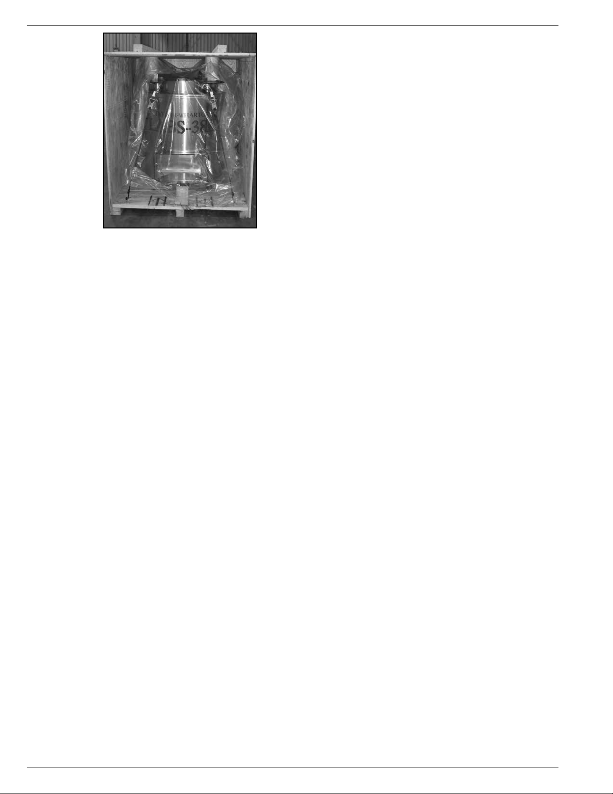
Figure 1.0 Crated LABS 38K
KRYOS
6
KRYOS
DELIVERY AND RETURNS
Unpacking and Inspection
Inspect shipping containers for external damage.
All claims for damage (apparent or concealed)
or partial loss of shipment must be made in
writing within five (5) days from receipt of goods.
If damage or loss is apparent, please notify the
appropriate parties as indicated below:
Domestic LTL Shipments – The customer
should notify and file the appropriate damage
claims with the carrier. All products are shipped
FOB Origin.
Domestic UPS Shipments – Any damage
should be noted and reported to shipper upon
delivery, and Taylor-Wharton must also be notified. Confirm with Taylor-Wharton
Customer Service the filing procedures for any UPS damage claims.
International Shipments – Any damage and/or claims are to be filed with the
carrier. Insurance agent(s) and customs’ brokers should also be notified.
In all cases, Taylor-Wharton should be notified so we can assist if needed
in filing damage claims.
Open the shipping containers; a packing list is included with the system to simplify
checking that all components, cables, accessories, and manuals were received.
Please use the packing list to check off each item as the system is unpacked. Inspect
for damage. Be sure to inventory all components supplied before discarding any
shipping materials. If there is damage to the system during transit, be sure to file
proper claims promptly. Please advise Taylor-Wharton of such filings. In case of parts
or accessory shortages, advise Taylor-Wharton immediately. Taylor-Wharton cannot
be responsible for any missing parts unless notified within 60 days of shipment.
Freight Damage Procedures
Any freight damage claims are your responsibility. Cryostorage Systems
are delivered to your carrier from Taylor-Wharton’s dock in new
condition; when you receive our product you may expect it to be in that
same condition. For your own protection, take time to visually inspect each
shipment in the presence of the carrier’s agent before you accept delivery. If any
damage is observed, make an appropriate notation on the freight bill. Then, ask the
driver to sign the notation before you receive the equipment. You should decline to
accept containers that show damage which might affect serviceability.
Repackaging for Shipment
If it is necessary to return any part of the system for repair or replacement, a
Material Return Authorization (MRA) number must be obtained from an authorized
factory representative before returning the equipment to our service department.
Contact your distributor for return authorization. When returning equipment for
service, the following information must be provided before obtaining an MRA:
A. System model and serial number, and controller model and unit, if available.
B. User’s name, company, address, and phone number
C. Malfunction symptoms
Figure 1.0 Crated LABS 38K

7
KRYOS
If possible, the original packing material should be retained for reshipment. If not
available, consult Taylor-Wharton for shipping and packing instructions. It is the
responsibility of the customer to assure that the goods are adequately packaged for
return to the factory. All refrigerators returned to Taylor-Wharton must be clean and
sterile before return. See page 13 for cleaning instructions.
INSTALLATION
Getting Unit into Service
Your Cryostorage System should come with complete instructions for how you should
remove the unit from the crate and put it into service. Read both this manual and
your Cryostorage System’s manual before beginning any installation. Make sure to
follow any required procedures and safety guidelines when you are hooking up your
Liquid Nitrogen source.
Electrical
The liquid level controllers used with these refrigerators operate from 24/16.5 VAC.
However, the external transformer does have a 110/220 VAC primary. Disconnect
the electrical power cord from the outlet before attempting any service.
Power Supply Connection
Connect the power supply to your LABS or K-Series Cryostorage System and then
plug the power supply into a surge protected 110/220 VAC outlet.
OPERATION
These instructions are for operators experienced with cryogenic equipment. Before
operating the system, become familiar with the safety precautions in this manual
and in reference publications. Make certain all applicable provisions set forth in the
Installation Section have been followed before placing a system in operation. Study
this manual thoroughly. Know the location and function of all system components.
Initial Fill
The Cryostorage System using the KRYOS controller, comes preset from the factory.
The liquid nitrogen supply pressure at the inlet to the refrigerator should be in
the range of 10 psig (0.7 bar/69 kPa) to 20 psig (1.4 bar/138 kPa) for optimum
performance. Higher operating pressures will increase transfer losses and create
excessive turbulence of the liquid in the refrigerator which can generate false signals
to the liquid level controller causing the refrigerator to under fill. In “liquid phase”
storage applications, excessive turbulence can cause splashing which could result in
personal injury.
Control Components
Interface Panel
The KRYOS Interface panel, which the user will interact with, contains the vacuum
fluorescent display as well as the number keypad, power button, help button and the
soft-key control buttons. (See Figure 2.0 and 2.1 on following page.)
WARNING:
Electrical shock can
kill. Do not attempt
any service on these
units without first
disconnecting the
electrical power cord.
CAUTION:
If using a power
source other than
North American
110/220 VAC,
contact Taylor-
Wharton Customer
Service to make
sure you are using
the appropriate
converter. Use of an
unapproved power
source converter may
cause permanent
damage to the unit.
NOTE:
For KRYOS Field
Installation instructions
refer to Page 35.
WARNING:
Maintain adequate
ventilation to
prevent asphyxiation
hazard (see Safety
Precautions).
WARNING:
If the fill fails to
stop for any reason,
quickly close the
liquid supply valve
to prevent overfilling
until the cause of
the problem can be
determined.
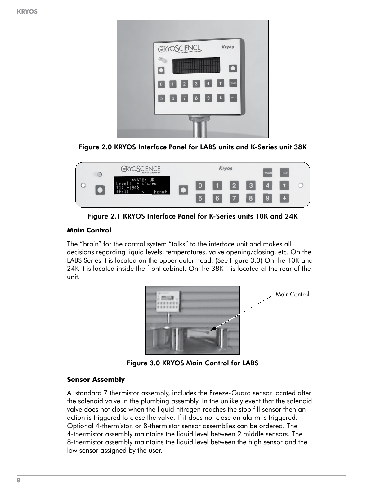
Figure 2.0 KRYOS Interface Panel for LABS units and K-Series unit 38K
Figure 2.1 KRYOS Interface Panel for K-Series units 10K and 24K
Main Control
The “brain” for the control system “talks” to the interface unit and makes all
decisions regarding liquid levels, temperatures, valve opening/closing, etc. On the
LABS Series it is located on the upper outer head. (See Figure 3.0) On the 10K and
24K it is located inside the front cabinet. On the 38K it is located at the rear of the
unit.
Main Control
Figure 3.0 KRYOS Main Control for LABS
Sensor Assembly
A standard 7 thermistor assembly, includes the Freeze-Guard sensor located after
the solenoid valve in the plumbing assembly. In the unlikely event that the solenoid
valve does not close when the liquid nitrogen reaches the stop fill sensor then an
action is triggered to close the valve. If it does not close an alarm is triggered.
Optional 4-thermistor, or 8-thermistor sensor assemblies can be ordered. The
4-thermistor assembly maintains the liquid level between 2 middle sensors. The
8-thermistor assembly maintains the liquid level between the high sensor and the
low sensor assigned by the user.
KRYOS
8
KRYOS
KRYOS
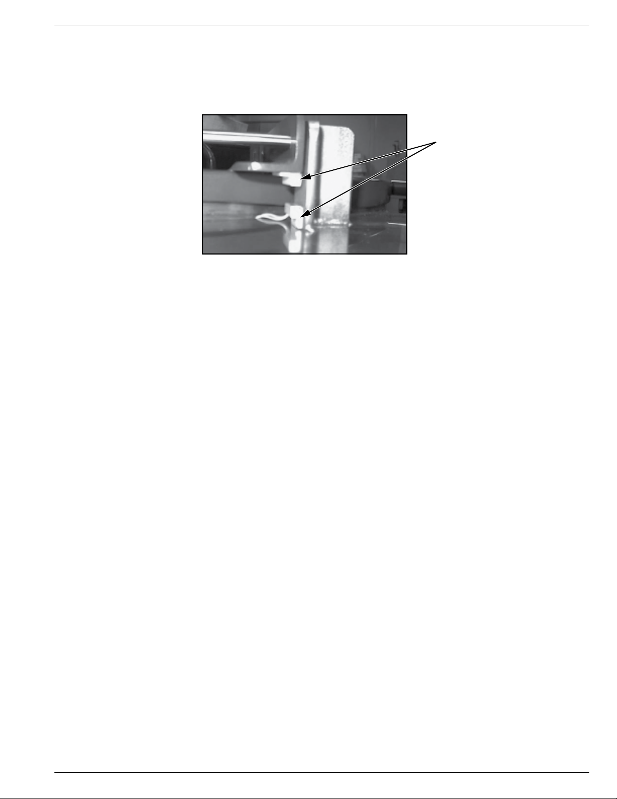
Lid Switch
The LABS and 38K Lid Switch (Fig 4.0) is attached to the hinge while the K-Series
Lid Switch is attached to the lid and determines whether or not the lid is open on the
freezer. This also allows the control to determine whether to activate the Quick Chill,
Auto Defog or Lid Alarm features.
Lid Switch
Figure 4.0 LABS and 38K Lid Switch
Solenoid Valve
These units are designed to work with 12 VDC solenoid valve manufactured by
ASCO (see Plumbing Assembly Figures on pages 29 and 30).
Thermocouples
Type T thermocouples determine the temperature in the freezer. The user may
choose to use NONE, 1 or 2 thermocouples with this control at any time. (The unit
comes complete with one Thermocouple)
Wall Transformer
A 24 VAC wall transformer is supplied for the KRYOS version (No Battery). The
system is supplied with a transformer compatible with common household (North
American) 110VAC. (For other power outlets contact Taylor-Wharton Customer
Service.) These wall transformers have UL approval. UL approval for the system as a
whole is not required since the control operates on low voltage. If your power source
differs, or is subject to disruption or line surges due to other equipment on line,
consult your Taylor-Wharton representative.
Optional Wall Transformer with Battery Back-up
This option has a 12VDC battery installed underneath the unit’s tabletop for the
LABS units and at the rear on the K-Series units.
Remote Alarm
If an error condition occurs after a user defined period of time, a remote alarm
circuit can be initiated. This is accomplished by connecting a remote device to
the remote alarm jack on the rear electrical panel. The 3-pin jack on the back of
the unit provides continuity between pin #2 (common) and pin #3 in the normal
condition. Continuity between pin #1 and pin #2 is provided in an error condition.
(See Figure 5.0 below.)
9
KRYOS
Lid Switch
The LABS and 38K Lid Switch (Fig 4.0) is attached to the hinge while the K-Series
Lid Switch is attached to the lid and determines whether or not the lid is open on the
freezer. This also allows the control to determine whether to activate the Quick Chill,
Auto Defog or Lid Alarm features.
Lid Switch
Figure 4.0 LABS and 38K Lid Switch
Solenoid Valve
These units are designed to work with 12 VDC solenoid valve manufactured by
ASCO (see Plumbing Assembly Figures on pages 29 and 30).
Thermocouples
Type T thermocouples determine the temperature in the freezer. The user may
choose to use NONE, 1 or 2 thermocouples with this control at any time. (The unit
comes complete with one Thermocouple)
Wall Transformer
A 24 VAC wall transformer is supplied for the KRYOS version (No Battery). The
system is supplied with a transformer compatible with common household (North
American) 110VAC. (For other power outlets contact Taylor-Wharton Customer
Service.) These wall transformers have UL approval. UL approval for the system as a
whole is not required since the control operates on low voltage. If your power source
differs, or is subject to disruption or line surges due to other equipment on line,
consult your Taylor-Wharton representative.
Optional Wall Transformer with Battery Back-up
This option has a 12VDC battery installed underneath the unit’s tabletop for the
LABS units and at the rear on the K-Series units.
Remote Alarm
If an error condition occurs after a user defined period of time, a remote alarm
circuit can be initiated. This is accomplished by connecting a remote device to
the remote alarm jack on the rear electrical panel. The 3-pin jack on the back of
the unit provides continuity between pin #2 (common) and pin #3 in the normal
condition. Continuity between pin #1 and pin #2 is provided in an error condition.
(See Figure 5.0 below.)
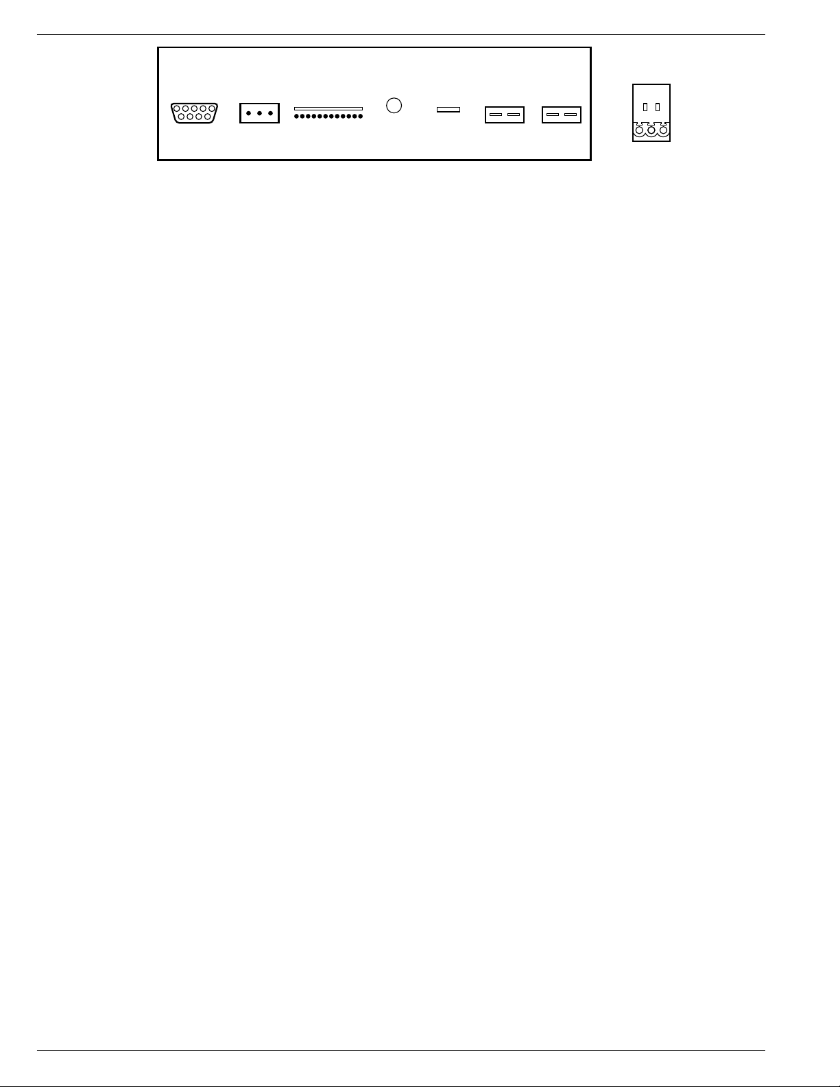
Comm Port
(RS-232)
Remote
Alarm
Remote Alarm:
Normal Condition............. Continuity Between pins 2 and 3
Alarm Condition................. Continuity Between pins 1 and 2
Sensor 24 VAC
Power
Solenoid Temp 1
(Receptacle
View)
Temp 2
3
1 - Purple Wire: Normally Closed
2 - Orange Wire: Normally Open
3 - Grey Wire: Normally Open
21
Figure 5.0 Remote Alarm Plug Connection
Operating Parameters
When materials are immersed in liquid nitrogen, they will assume the temperature
of the liquid (-196°C/-320°F). When material is stored in the vapor phase over the
liquid, the liquid nitrogen is still a very cold refrigerant, but the refrigerator’s interior
temperature increases somewhat as product is stored higher over the liquid. This
temperature differential is not significant in many biological storage applications,
and is affected by the amount of product stored in the refrigerator, the type and size
of inventory control system, and the liquid level in the unit.
The liquid level in the refrigerator is determined by the position of the of the
Thermistor Assembly in the sensor tube. These sensors are set at installation to
maintain a specific liquid level. A filling cycle is initiated when the level falls below
the Start Fill sensor and is completed when the Stop Fill sensor is reached. This
filling cycle repeats when the level fall below the Start Fill sensor. Sensor Probe
assignments may be changed on the controller keypad to define new start and stop
levels, and these levels may be set independently to vary the liquid level differential
between fills. Prior to the initial fill of the refrigerator, a determination should be
made whether vapor phase or liquid phase storage will be utilized.
All units are supplied with a seven thermistor assembly and a freeze-guard sensor
unless otherwise specified. Factory setting positions for the K-Series are Start Fill 3 in.
(76.2 mm) and Stop position 6 in. (152.4 mm). The LABS factory setting positions
will maintain liquid level within a distance of 2 in. (50.8 mm) from the bottom of the
operating tray on the LABS 20K, 38K, 40K, 80K units, and 3 in. (76.2 mm) from the
bottom of the operating tray on the LABS 94K.
Liquid Phase Storage
Liquid phase storage is normally utilized when liquid nitrogen temperatures are
required to maintain stored product viability and the storage medium is adequate
for storage in liquid nitrogen.
In a typical liquid phase storage system, the liquid level sensors are positioned to
maintain the liquid level at or below the top level of the inventory control system.
During operation, the upper levels of the inventory control system will at times
become exposed as the liquid level fluctuates.
Care must be taken to ensure that the liquid level remains below the bottom of the
refrigerator lid. Exposure to liquid nitrogen may result in physical damage to the lid.
Additionally, operating the refrigerator with high liquid levels characteristic of liquid
phase storage may result in turbulence during fill cycles. Caution must be exercised
if the refrigerator lid is opened during a fill, and appropriate safety equipment
should always be worn.
KRYOS
10
KRYOS
Comm Port
(RS-232)
Remote
Alarm
Remote Alarm:
Normal Condition............. Continuity Between pins 2 and 3
Alarm Condition................. Continuity Between pins 1 and 2
Sensor 24 VAC
Power
Solenoid Temp 1
(Receptacle
View)
Temp 2
3
1 - Purple Wire: Normally Closed
2 - Orange Wire: Normally Open
3 - Grey Wire: Normally Open
21
Figure 5.0 Remote Alarm Plug Connection
Operating Parameters
When materials are immersed in liquid nitrogen, they will assume the temperature
of the liquid (-196°C/-320°F). When material is stored in the vapor phase over the
liquid, the liquid nitrogen is still a very cold refrigerant, but the refrigerator’s interior
temperature increases somewhat as product is stored higher over the liquid. This
temperature differential is not significant in many biological storage applications,
and is affected by the amount of product stored in the refrigerator, the type and size
of inventory control system, and the liquid level in the unit.
The liquid level in the refrigerator is determined by the position of the of the
Thermistor Assembly in the sensor tube. These sensors are set at installation to
maintain a specific liquid level. A filling cycle is initiated when the level falls below
the Start Fill sensor and is completed when the Stop Fill sensor is reached. This
filling cycle repeats when the level fall below the Start Fill sensor. Sensor Probe
assignments may be changed on the controller keypad to define new start and stop
levels, and these levels may be set independently to vary the liquid level differential
between fills. Prior to the initial fill of the refrigerator, a determination should be
made whether vapor phase or liquid phase storage will be utilized.
All units are supplied with a seven thermistor assembly and a freeze-guard sensor
unless otherwise specified. Factory setting positions for the K-Series are Start Fill 3 in.
(76.2 mm) and Stop position 6 in. (152.4 mm). The LABS factory setting positions
will maintain liquid level within a distance of 2 in. (50.8 mm) from the bottom of the
operating tray on the LABS 20K, 38K, 40K, 80K units, and 3 in. (76.2 mm) from the
bottom of the operating tray on the LABS 94K.
Liquid Phase Storage
Liquid phase storage is normally utilized when liquid nitrogen temperatures are
required to maintain stored product viability and the storage medium is adequate
for storage in liquid nitrogen.
In a typical liquid phase storage system, the liquid level sensors are positioned to
maintain the liquid level at or below the top level of the inventory control system.
During operation, the upper levels of the inventory control system will at times
become exposed as the liquid level fluctuates.
Care must be taken to ensure that the liquid level remains below the bottom of the
refrigerator lid. Exposure to liquid nitrogen may result in physical damage to the lid.
Additionally, operating the refrigerator with high liquid levels characteristic of liquid
phase storage may result in turbulence during fill cycles. Caution must be exercised
if the refrigerator lid is opened during a fill, and appropriate safety equipment
should always be worn.
 Loading...