

Page 1
Instructions for
XL-160 and XL-180
TW-72
Do not attempt to use or maintain this
unit until you read and understand these
instructions. Do not permit untrained
persons to use or maintain this unit. If
you do not fully understand these instructions, contact your supplier for further
information.
Page 2

Contents
Container Safety ....................................................................... 1
General Information .................................................................. 2
Specifications ............................................................................ 2
Operation...................................................................................4
Component Descriptions............................................. 4
Withdraw Liquid from the Container ........................... 5
Filling the Container .................................................... 5
Fill Hose Kits ............................................................... 6
Maintenance .............................................................................. 8
Checking Container Performance ................................ 8
Hand V alve Repair ....................................................... 9
Shock Mount Foot Ring .............................................. 9
Full V iew Contents Gauge Maintenance...................... 1 0
T r oubleshooting ........................................................................ 13
Replacement Parts .................................................................... 14
Accessories 14
Page 3

Pressure Hazard – The containers covered by this literature contain liquefied gas
under pressure. Sudden release of this pressure may cause personal injury by
issuing cold gas or liquid, or by expelling parts during servicing. Do not attempt any
repairs on these containers until all pressure is released, and the contents have
been allowed to vaporize to ensure no pressure buildup can occur.
Extreme Cold – Cover Eyes and Exposed Skin – Accidental contact of the skin or
eyes with any cryogenic liquid or cold issuing gas may cause a freezing injury
similar to frostbite. Protect your eyes and cover your skin when handling the container or transferring liquid, or in any instance where the possibility of contact with
liquid, cold pipes, and cold gas may exist. Safety goggles or a face shield should be
worn when withdrawing liquid or gas. Long-sleeved clothing and gloves that can be
easily removed are recommended for skin protection. Cryogenic liquid is extremely
cold and will be at temperatures below -300° F (-184°C) under normal atmospheric
pressure.
Keep Equipment Well Ventilated – Although the gases used in these containers
are non-toxic and non-flammable, they can cause asphyxiation in a confined area
without adequate ventilation. An atmosphere that does not contain enough oxygen
for breathing can cause dizziness, unconsciousness, or even death. These gases
cannot be detected by the human senses and will be inhaled normally as if they
were air. Ensure there is adequate ventilation where these gases are used and store
liquid containers outdoors or only in a well ventilated area.
Replacement Parts Must be Clean to Prevent Contamination – Use only TaylorWharton recommended spare parts, and be certain parts used are properly cleaned
to prevent contamination of stored product. For information on cleaning, consult the
Compressed Gas Association (CGA) pamphlet1 G-4.1, “Cleaning for Oxygen
Service” or equivalent industrial cleaning specifications.
Container
Safety
NOTE:
For detailed information on teh
handling of cryogenic liquids, refer
to the Compressed Gas Association
publication(1): P-12 “Safe Handling
of Cryogenic Liquids.”
Install Relief Valves in Cryogenic Liquid Lines – When installing or fill hose
assemblies, make certain a suitable safety relief valves is installed in each section
of plumbing between shut-off valves. Trapped liquefied gas will expand as it warms
and may burst hoses or piping causing damage or personal injury.
1
Available from the Compress Gas Association, 1235 Jefferson Davis Highway,
Arlington, VA 22202.
Page 4
q
y
General
Information
Specifications
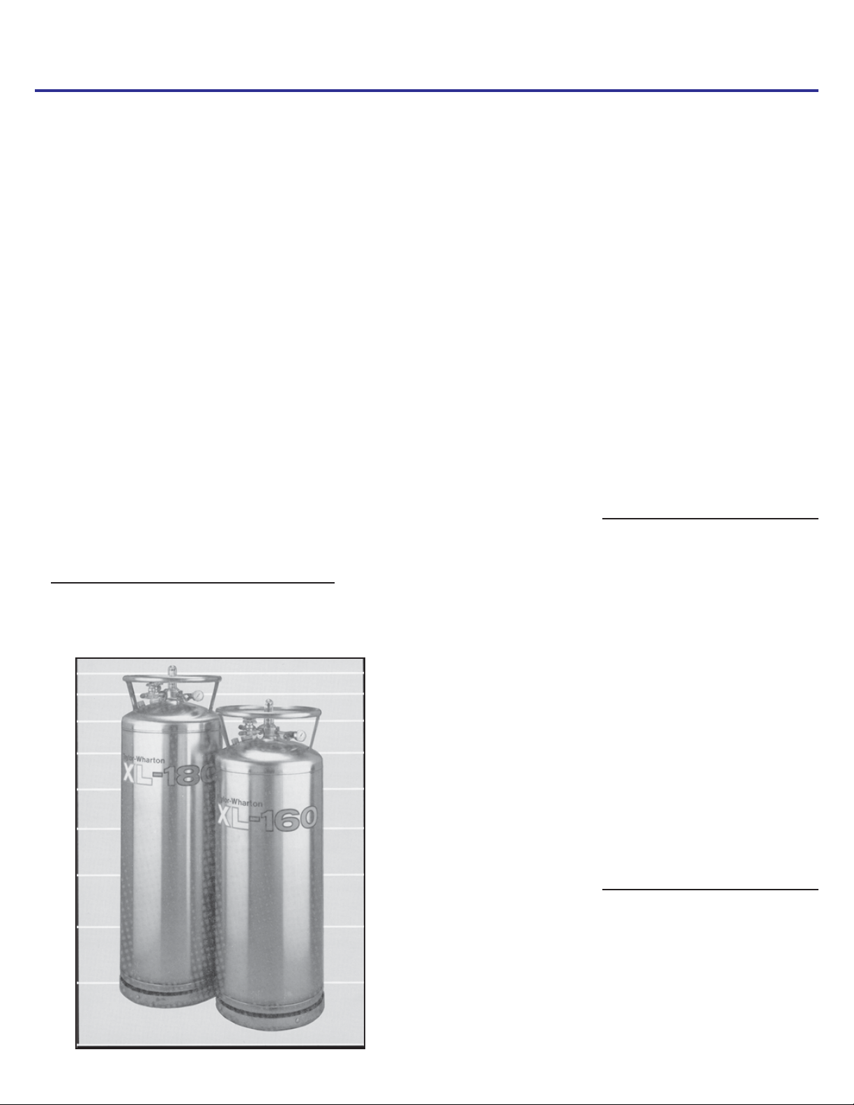
The XL-160 and XL-180 are vacuum insulated, stainless steel containers designed to
store, transport, and dispense cryogenic liquid nitrogen. Built to DOT 4L standards,
these containers may be used for over-the-road transportation, as well as on-site
storage and supply.
Dimensions (Nominal)
Diameter
Height
Weight
Empty 197 lb. (89 kg) 205 lb. (93 kg)
Approximate Weight of Contents
(Nitrogen) in 22 psig (1.5 bar/152
kPa) Service
Capacity, Gross 163 liters 186 liters
Capacity, Useable Liquid 160 liters 180 liters
Normal Evaporation Rate* (%
Capacity per Day)
Nitrogen 1.3% 1.25%
Relief Valve Setting 22 psig
Inner Container Bursting Disc 176 psig
Design Specifications
T/DOT
Rated Service Pressure
Specifications are subject to change without notice.
*Vented N.E.R. based on Useable Li
20 in. (508 mm)
57 5/8 (1464 mm)
259 lb. (117 kg) 296 lb. (134 kg)
(1.5 bar/152 kPa)
(12 bar/ 1214 kPa)
4LM/4L
100 psig
(6.9 bar/ 690 kPa)
uid Capacit
XL-160 XL-180
20 in. (508 mm)
64 3/8 in. (1635 mm)
22 psig
(12 bar/1214 kPa)
176 psig
(12 bar/1214 kPa)
4LM/4L
100 psig
(6.9 bar/690 kPa)
Page 5
Handling the Container
XL Series containers are very rugged liquid cylinders. All cryogenic liquid containers
have an inner container and on outer container with an insulated vacuum space
between them; any abuse (dents, dropping, tip-over, etc.) can affect the integrity of
the container’s insulation system.
When fully loaded, the XL-180 in nitrogen service will contain up to 296 lb. (134 kg)
of product. While moving a full container, you may be handling up to 501 lb. (227 kg),
and you should treat the load accordingly. The attachment points provided on the Xl160/XL-180 will allow you to use a hand truck, or a hoist, to handle these loads
properly. Do not attempt to move these cylinders by any other means. When moving
the cylinder, the following precautions should be observed:
Never lay the container on its side. Always ship, operate, and store the
unit in a vertical or upright position.
When loading or unloading the container from a truck, use a lift gate, a
crane, or a parallel loading dock. Never attempt to manually lift from the
unit.
To move the container over rough surfaces or to life the container, attach
an appropriate sling to the lifting points cut into the welded support posts,
and use a portable lifting device that will handle the weight of the container.
Freight Damage Precautions
XL-160 and XL-180 Liquid Cylinders
Any Freight Damage claims are
your responsibility. Cryogenic
liquid containers are delivered to
your carrier from Taylor-Wharton’s
dock in new condition. When you
receive our product you may
expect it to be in that same
condition. For your own protection, take time to visually inspect
each shipment in the presence of
the carrier’s agent before you
accept delivery. If any damage is
observed, make an appropriate
notation on the freight bill. Then
ask the driver to sign the notation
before you receive the equipment.
You should decline to accept
containers that show damage
which may affect service ability.
Page 6
Operation
The model numbers of XL-160/XL-180 indicate their respective liquid storage capacities
in liters of product. Both cylinders are designed for liquid nitrogen service only. The
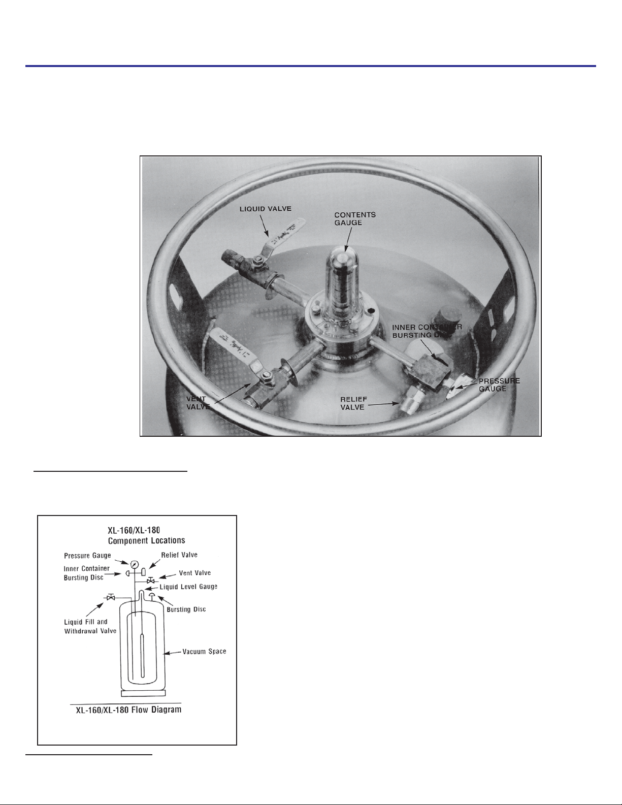
following component and circuit descriptions are pertinent to either container and should
be read before attempting operation. The components may be identified on the Component Location illustration.
XL-160/XL-180 Component Locations
The Liquid Valve - Liquid product is added or withdrawn from the container through the connection controlled by this valve. It has the CGA
fitting that is required for liquid connections.. The valve is opened for fill
or liquid withdrawl after connecting a transfer hose with compatible fittings
to the LIQUID line connection.
The Pressure Gauge - Thepressure gauge dsplays teh internal container
pressure in pounds per-square-inch, bar or in kiloPascals.
The VENT Valve - This valve controls a line into the head space of the
container. It is used during thet fill process. the VENT valve is opened to
vent the head space area while liquid is entering the inner container
during a pressure transfer fill through the LIQUID valve.
The Full View Contents Gauge - The container contents gauge is a float
type liquid level sensor that indicates container liquid content through a
magnetic coupling to a yellow indicator band. This gauge is an indication
of approximate container contents only and should not be used for filling.
Relief Devices - These cylinders have inner container relief valves set at
22 psig (1.5 bar/152kPa) and inner container bursting disc that will rupture
at 176 psig (12 bar/1213)
XL-160/XL-180 Flow Diagram
Page 7

Withdrawing Liquid From The Container
To use the container in liquid delivery service, attach a transfer hose to the LIQUID
connection and open the adjacent LIQUID valve. The pressure in the container will
drive liquid product out through the valve as long as the container pressure exceeds
trhat of the receiver.
CAUTION:
To avoid contamination, close
the LIQUID valve before disconnecting the transfer line.
The rate of liquid withdrawal from these containers is variable depending on teh
container pressure and the saturation temperature of the liquid. With liquid saturated
at 22 psig (1.5 bar/152 kPa) withdrawal rate of up to 6 liters/min can be obtained.
WITHDRAWING LIQUID FROM THE CONTAINER
To use the container in liquid delivery service, attach a transfer hose to the LIQUID
connection and open the adjacent LIQUID valve. The pressure in the container will
drive liquid product out through the valve as long as the container pressure exceeds
that of the receiver.
The rate of liquid withdrawal from these containers is variable depending on the
container pressure and the saturation temperature of the liquid. With liquid saturated
at 22 psig (1.5 bar/152 kPa) withdrawal rate of up to 6 liters/min can be obtained.
Filling the Container
Cryogenic liquid containers that operate below 25 psig (1.7 bar/172 kPa) may be filled
by weight or by volume. The latter method depends on the filler observing liquid
product exiting the vent valve as an indication that the container is full. Both methods
are listed here. Be certain to observe all safety precautions associated with the
handling of cryogenic liquids.
Filling the Container by Weight of Contents
Using the procedures below, first determine the proper filled weight of each container.
The weight derived is then used in the filling procedure that follows.
WARNING:
Filling operations should take
place only in well ventilated
areas. Accumulations of
product gas can be very dangerous (refer to the safety precautions in the front of these
instructions). Maintain adequate ventilation at all times.
1. Visually inspect the container. Do not attempt to fill containers that have broken or
missing components.
2. Move the container to a filling station scale and weigh it both with, and without,
the fill hose attached to determine the weight of the fill line assembly. The difference is the fill line weight.
3. To determine the weight at which the fill should be stopped, add the desired filling
weight, the transfer line weight, and the Tare Weight from the container’s data
plate.
4. Once you have determined the proper fill weight for the container, connect a
transfer hose to the LIQUID fitting from a low pressure sources of liquid.
5. Open the supply valve. Then, on the XL-160/XL-180, open the LIQUID and VENT
valves to begin the fill.
6. During the fill, monitor the container pressure and maintain a pressure of 10-15
psig (0.7 bar/69-103 kPa) by throttling the VENT valve.
7. When full weight is reached, close both the LIQUID and the VENT valves.
8. Close the liquid supply valve and open the dump valve on the fill line assembly.
9. Disconnect the fill line from the container and remove the container from the scale.
Liquid Withdrawal
NOTE:
The fill weight calculation
inlcudes the weight of residual
liquid. the weights shown in the
Specifications are for liquid
saturated at atmospheric pressure. The actual fill weight for
your applaction depends on the
saturation temperature of liquid
in your storage tank, and mayh
be determined by weighing
cylinders that have been filled by
volume.
Page 8

Pressure Transfer Filling
Filling the Container by Volume
1. Visually inspect the container. Do not attempt to fill containers that have broken or
missing components.
2. Connect a transfer hose to the LIQUID fittings from a low-pressure source of liquid.
3. Open the supply valve. Then, on the XL-160/XL-180, open the LIQUID and VENT
valves to begin the fill.
4. When liquid begins to spit from the VENT valve, quickly close the LIQUID valve
and then the VENT valve. Both valves must be closed before the container relief
valve opens.
5. Open the dump valve on fills line assembly to vent the fill line assembly.
6. Disconnect the fill line from the container.
Fill Hose Kits
Taylor-Wharton fill hose kits for the XL-160/XL-180 are designed to transfer liquefied
gases to, or from the containers. These accessories are comprised of a Fill Tee Assembly and a Fill Hose. Cryogenic transfer hoses are constructed of stainless steel suitable
for cryogenic liquids, and are available in 4 or 6-ft. (1.2 or 1.8 m) lengths with a 3/8 in.
NPT fitting on one end and CGA service specific female fittings on the other. A Fill Tee
Assembly consists of a cross fitting with a CGA end fitting, relief valve and manual
dump vave.
Fill Hose Kits
Page 9

In use, the CGA end fitting on the Fill/Vent Tee Assembly couples to the fill connection
to be filled. The Relief Valve vents pressure over 350 psig (24-bar/2413 kPa) that builds
up in the fill line due to trapped liquid. The Dump Valve is used to allow the operator to
blow-down in the receiving container during a pump fill, or to relieve residual pressure
from expanding liquid trapped before disconnecting the fill line.
Fill kits are available with different combinations of hose length. The following chart
identifies the available transfer hoses and the Fill/Vent Tee assemblies that are appropriate for use with the XL-160/XL-180.
Transfer Hoses & FILL/VENT Tee Assemblies
The Fill/Vent Tee connects to a transfer hose to complete a fill line kit. Each assembly
includes a 3/8-in. pipe connector to CGA fitting with a 350-psig (24-bar/2413-kPa) relief
valve, and a ball-type dump valve.
Description Cylinder
Connections
Hose, 4 ft. (1.2 m) SS LIQUID or VENT valve CGA 295 to 3/8 in NPT 1700-9C65
Hose, 6 ft. (1.8 m) SS LIQUID or VENT valve CGA 295 to 3/8 in NPT 1600-9C66
Fill/Vent Tee Assemb. LIQUID or VENT valve CGA 295 GL50-8C60
End
Fittings
Part
Number
Page 10

Maintenance Read the Safety Precautions in the front of this manual before attempting any repairs
on these containers. Also, follow these additional safety guidelines while performing
container maintenance.
Never work on a pressurized container. Open the vent valve as a standard
practice during maintenance to guard against pressure build-up from residual
liquid.
Use only repair parts for oxygen service. Be certain your tools are free of oil and
grease. This is a good maintenance practice and helps ensure you do not introduce
any contaminants to the plumbing of the container.
Leak test connections after every repair. Pressurize the container with an appro
priate inert gas for leak testing. Use only approved leak test solutions and follow the
manufacturers recommendations. “Snoop” Liquid Leak Detector is one approved
solution. It is available from Nupro Co., 4800 E. 345
USA.
CHECKING CONTAINER PERFORMANCE
Cryogenic containers are two containers, one within the other. The space between the
containers acts as a highly efficient thermal barrier including high technology insulation,
and a vacuum maintenance system. Each serves a very important part in the useful life
of the container. The high technology insulation is very effective in preventing radiated
heat or solid conduction from entering the container; the vacuum prevents heat convection from reaching the stored product. Unfortunately, the perfect vacuum cannot be
achieved since trace gas molecules begin to enter the vacuum space from the moment
of manufacture. The vacuum maintenance system consists of materials which gather
gas molecules from the vacuum space. The maintenance system can perform its
function for years, but has a limited capacity. When the vacuum maintenance system is
saturated, it can no longer maintain the vacuum integrity of the container. The change
will be very gradual and may go unnoticed for several years. When the vacuum in the
insulation space is no longer effective, the following symptoms may appear.
th
St., Willoughby, Ohio 44094
1. When the container is filled with liquid, the outer casing will be much colder than
normal.
2. The container may appear to “sweat” if the air surrounding the container is hot and
humid.
3. The relief valve will open continuously until the container is empty.
4. The container will hold pressure for several days, but will not hold liquid.
NER TESTING
If a loss of vacuum integrity is suspected, the container’s Normal Evaporation Rate
(NER) should be checked. The test measures the actual product lost over time so you
can compare the results obtained to the NER value in the SPECIFICATIONS table. A
test period of 48 hours is recommended, after the container is allowed to stabilize, but
the formula given produces a Daily NER over any time period.
1. Fill the container with 150 pounds (68 kg) of liquid nitrogen.
2. Close the LIQUID valve, open the VENT valve and allow it to remain open during
the test.
Page 11

3. Allow the container to stabilize for 24 hours, then weigh it. Record the weight, time
and date.
4. Reweigh after the recommended 48 hours. The test if most effective if the
container is not moved during this period, and if conducted in an area where
ambient temperatures are consistent.
The following calculation will provide the actual Normal Evaporation Rate.
NOTE:
Fill through the LIQUID valve with
VENT valve open
.
Daily NER =
Weight Loss (Step 3-Step4) x 24 hours
Elapsed Time (Hrs.)
Compare the results of your test to the “as manufactured” NER value in the SPECIFICATIONS section of this manual. A container in service should maintain an NER value
of less than two times the new specification. Any test result greater than two times the
listed value is indicative of a failed, or failing, vacuum. If NER is found to be high,
contact Taylor-Wharton Customer Service at (334) 443-8680 for disposition.
HAND V ALVE REPAIR
The ball valves used on the XL-160/XL-180 may be replaced by removing fittings
and unscrewing the valve body from the container plumbing. When installing a new
valve, it is important to close the valve, and observe the presence of a small hole in the
ball that is visible through only one of the threaded openings in the valve body. This
hole is a vent that allows the valve to prevent pressure buildup due to liquid trapped in
the ball chamber when the valve is closed. When installing a replacement valve,
always check to ensure the hole faces the container when the valve is closed.
SHOCK MOUNT FOOT RING
Item No. Description Part. No. Qty.
1 Rubber Shock Ring XL50-4C18 1
2 Foot Ring XL50-4C19 1
3 Hex Nut 6310-0135 4
4 Washer 6430-0125 4
5 Carriage Bolt 6620-0401 4
NOTE:
IF the original Shock Mount Ring is
badly damaged we recommend that an
NER test is performed to ensure that no
internal damage has resulted from the
impact of teh shock mount ring.
Replacement of Shock Mount Foot Ring
1. Empty or transfer all contents of tank. Vent to atmospheric pressure.
2. Gently lay the tank on its side and unbolt the four (4) carriage bolts that attach
the foot ring and rubber shock ring to the tank.
3. Slide off the damaged foot ring and rubber shock ring.
4. Assemble rubber shock ring into new foot ring and force over shock mount ring on
vessel. Use a rubber hammer to drive the rubber shock ring into place.
5. Using a ½ in. drill bit, drill holes through the rubber so that the carriage bolt slides
in smoothly.
6. The holes in foot ring must be positioned in alignment with hole in shock mount
ring. Using the 4 bolts, washers and nuts, fasten the new parts of the cylinder.
7. After securing the shock mount ring to the tank, gently life the tank to the upright
position and inspect your work.
Shock Mount Foot Ring -
Exploded View
Page 12

WARNING:
Cold surfaces should never be handled
with bare skin. Use gloves and other
protective clothing when performing
this procedure.
FULL VIEW CONTENTS GAUGE MAINTENANCE
The contents of these containers is measured with the Full View Contents Gauge. The
device consists of the gauge assembly beneath a clear plastic protective cover. When
the gauge is assembled, a level indicator ring is magnetically coupled to the top of a
float rod and moves up or down with the changing level of liquid in the container. The
clear cover over the gauge body and level indicator is sealed at assembly to resist
fogging of the gauge. This seal should never need to be broken.
If the level indicator does not move when container is filled, it may indicate that the
magnetic field between the level indicator and the gauge has been uncoupled. The
level indicator should recouple itself as the container is emptied. However, a reengagement tool (ring) is available to correct the problem immediately. To reestablish
the correct relationship, slip the re-engagement ring over the contents gauge and its
protective cover. The magnetic field of this tool will allow you to lift the yellow level
indicator until it recouples with the magnetic field on the gauge rod.
Fill Dwawing
Full V iew Contents Gauge
Removing the Full View Contents Gauge
1. Vent all pressure from the container.
2. Remove the protective cover by removing three bolts from the base cover.
3. Unscrew the gauge body using a wrench on hex fittings at base of the indicator.
4. Lift the entire gauge assembly free of the container. The gauge assembly is long
and my be very cold. Gloves should be used to protect your skin.
Calibration Procedure for Liquid Level Contents Gauge
1. You will need a column of water approximately 4-ft. (1.2 m) tall. A clear plastic
tube 2.0-in. (51 mm) with a cap glued to one end of perfect.
2. Support the gauge assembly by holding the base of the indicator tube. Care must
be taken to prevent interference with the spring action. Partially immerse the
aluminum float road in the water. The water level should be 3.0 in. (76 mm) below
the top of the rod as illustrated. The gauge assembly must be held vertically and
the rod must not touch the side or bottom of the tube. The yellow level indicator of
the gauge should indicate a full reading with the scale.
If the gauge fails to indicate a full liquid level, the assembly is to be removed from the
water, calibrated and retested.
To change calibration, loosen locking nut away from brass calibration nut and turn the
threaded rod with respect to the calibration nut.
Page 13

If the rod is turned clockwise (to the left) with respect to calibration nut, the exposed
portion of rod becomes longer and the gauge yellow band will be lowered.
To raise the yellow band, turn rod counter clockwise. The exposed portion of rod becomes shorter. Once you had adjusted calibration, recheck for proper setting. (See
illustration.) After proper setting has been obtained, lock down nut against calibration
unit.
1. Once the gauge assembly has been calibrated to read in full water, it must be
verified that it reads empty when the aluminum float rod is suspended in the air. The
yellow indicator must be as close to the bottom as possible (inner rod will be firmly
bottomed out.)
If calibration is required to make the gauge read empty in air, it must be rechecked in
water.
2. After calibration, you will need to follow contents gauge installation to reinsert gauge.
Be sure to dry the assembly before reinserting into the cylinder to prevent ice build
up that could restrict movement or catch on the guide ring inside the cylinder.
NOTE:
The yellow band will move approximately1/4 in. (6.4 mm) to each 10
turns of the rod.
NOTE:
Remember this procedure is
performed with gauge in an upright
(vertical) position.
NOTE:
Make sure that the Gauge Assembly
is not bent or out of line gefore
reinserting teh gauge into the
container.
Calibration drawing
Contents Gauge Installation
Before installing a new or repaired gauge, inspect the gasket seals. If any damage is
apparent, replace the gasket. (See following page for illustration.)
1. When inserting the gauge assembly, lower the float rod through the gauge opening
until about 8 in. (203 mm) of the float rod remains above the container.
2. Grasp the clear cover portion of the gauge assembly with two fingers so that the
assembly hangs free and “plumb.”
Calibration for XL-160/XL-180
Page 14

CAUTION:
When installing the gauge assembly, care must be taken to ensure
that the float rod is inserted through
“guide ring” located on the liquid
withdrawal line inside container. IF
gauge does not engage this ring, the
contents indication will be inaccurate, or the gauge may be damaged
in use.
Contents Gauge Insertion
Lower the assembly about 4 in. (102 mm) slowly and try to keep the rod in the center of
the threaded entrance hole as you do. If you are careful during this portion of the insertion, you will drop the float rod straight though the guide ring inside the cylinder.
1. To confirm that the rod is correctly positioned in the cylinder, stop where you can
still grasp the top of the rod (see illustration) and try to swing the lower end from
side to side.
2. When the rod is engaged in the guide ring, the rod will be restricted to lower end
movement of about ½ in. (12.7 mm); if you can feel greater movement, withdraw
the rod to the point where its top is 8 in. (203 mm) above the gauge opening and try
again.
3. When you are satisfied that the float rod is correctly installed, lower the rest of the
way into the container until the top portion threads can be engaged.
4. Screw the gauge in place and hand torque to about 20 ft. lbf (2.8 kgf m). Leak check
the connection of gauge body to the flange.
Page 15

Sym ptom Possible Cause Corrective Action
Consistently low operating
pressure.
Very low or no pressure
show on gauge
C o n ta in e r is c o ld a n d m a y
have ice or frost on outer
casing. W ill not hold liquid
overnight. Relief valve is
venting gas.
Container vents after fill but
quits after a short tim e.
Float-type level indicator at
bottom of gauge. C ontainer
full of product.
1. Relief valve open at low
pressure.
2. Cold liquid.
1. Bad pressure gauge.
2. Ope n in ner container
sa fe ty h e a d .
3. Leaks in valves or
plumbing.
4. Liquid too cold.
5. Possible leak in VEN T
valve.
6. Faulty relief valve.
Vacuum loss. Check
vacuum burstin g disc.
This ma y be caused by
residual heat vaporizing
liquid inside container and
is a normal condition.
Indicator disengage d from
gauge rod magnetic field.
Caused by dropping the
container.
1. Rem ove and replace
re lief va lve .
2. Container pressure will
build over tim e, or an
external pressure
source can be used to
pressurize con tainer.
1. Rem ove and replace
bad gauge.
2. Rem ove and replace
safety head. Pressurize
container and check
relief valve operation .
3. Leak test and repair
leaks.
4. Allow contain er to stand
and build pressure.
5. Replace valve.
6. Replace valve.
C o n s u lt w ith T a y lo rW harton for course of
a c tion . D o n o t a tte m pt to
put additional liquid into
container.
Sym ptom should stop when
container reaches operating
temperature and the liqu id
reaches its saturation point
at container operating
pressure.
Re-couple indicator using
re-engage m ent ring.
Troubleshooting
Page 16

Replacement Parts
XL-160/XL-180
Component Locations
Accessories
Accessories available for use with Taylor-Wharton XL Series containers include:
· Manifolds, Automatic and Manual
· Transfer Hoses
· Fill/Vent Tee Assemblies
· Container Hand Trucks
· Cryogenic Phase Separators
For additional information concerning the accessory of your choice, please consult the separate manual on accesso-
ries or call Taylor-Wharton at (334) 443-8680.
Page 17

Index
No.
1. Gasket, Glass Filled Teflon 7701-0083 5 each
2. Float, Contents Gauge 1604-9C60 1 each
3. Contents Gauge Assembly
4. Screw, Contents Gauge Cover 6114-1087 3 each
5. Cover, Contents Gauge, Protective GL50-9C04 4 each
6. Gauge, Pressure 0-60 (4.1 bar/414 kPa) 7702-6192 2 each
7. Safety Head, 176 psig (12 bar/1213 kPa) L240-9C20 2 each
8. Relief Valve, 22 psig (1.5 bar/152 kPa) 6913-6223 5 each
9. Ball Valve ½ in. 6916-7114 3 each
10. Cross, Brass ¼ in. NPT GL55-9C30 2 each
11.
*
*
*
*
*
Description
(Includes Gauge and Spring)
End Fitting, CGA 295, Vent/Liquid
Decal Nitrogen
Decal, XL-160
Decal, XL-180
Decal, UN Number, Nitrogen
Decal, Warning
Part No. Recommended for 10
Units
GL50-9C42 1 each
7355-4698
GL55-9C51
1604-9C50
L180-9C50
GL55-9C63
1700-9C07
5 each
A/R
A/R
A/R
A/R
A/R
Page 18

Warranty
TAYLOR-WHARTON
XL Series Liquid Cylinders
Taylor-Wharton Gas Equipment Division, Harsco Corporation warrants that
each of its Refrigerator and Dewars will be free from defects in material and workmanship, in the normal service for which the product was manufactured, for a period
of ninety (90) days from date of shipment to the original purchaser. The product is
further warranted to maintain a Normal Evaporation Rate (NER) within 10% of TaylorWharton’s published specifications for the product, on date of shipment. This warranty is in effect for all XT, HC, LS, CX and LD Series products for a period of three
(3) years from date of shipment to the original purchaser, and for all Series products
for a period of two (2) years from date of shipment to original purchaser, if the
product is used and maintained according to Taylor-Wharton’’ instructions.
To make a claim under this warranty, the purchaser must: 1) give TaylorWharton written notice with ten (10) days after discovery of claimed defect, 2)
immediately discontinue use of the product, and 3) return such product freight paid to
the location specified by Taylor-Wharton for evaluation to validate warranty claim. If
the claimed defect is confirmed by Taylor-Wharton’s inspection, Taylor-Wharton will,
at its option and as the purchaser’s sole remedy, repair or replace such product or
any component part thereof, or refund the original purchase price.
This warranty is voided by alterations or by repairs by others. Taylor-Wharton
shall not be liable under this warranty, or otherwise, for defects caused by negligence,
abuses, or misuse of the product, corrosion, fire, heat, or the effects of normal wear.
Any related components or other equipment manufactured by other which may be
sold with Taylor-Wharton’s product are not covered y this warranty.
THIS WARRANTY IS IN LIEU OF ANY OTHER WARRANTIES, EXPRESS OR
IMPLIED, INCLUDING ANY IMPLIED WARRANTY OF MERCHANTABILITY OR
FITNESS FOR A PARTICULAR PURPOSE.
THE REMEDIES SET FORTH HEREIN ARE EXCLUSIVE TAYLOR-WHARTON
SHALL NOT BE LIABLE FOR ANY CONSEQUENTIAL, SPECIAL OR INCIDENTAL
DAMAGES RESULTING FROM THE DELIVERY, USE OR FAILURE OF THE
PRODUCT (INCLUDING LOSS OF ANY MATERIAL STORED IN THE PRODUCT),
OR FROM ANY OTHER CAUSE WHATSOEVER. BY ACCEPTING DELIVERY OF
THE PRODUCT SOLD HEREUNDER, THE PURCHASER ACKNOWLEDGES THAT
THIS LIMITATION REMEDIES IS REASONABLE AND ENFORCEABLE. IN NO
EVENT SHALL TAYLOR-WHARTON’S LIABILITY EXCEED THE PURCHASE
PRICE FOR THE PRODUCT.
Taylor-Wharton
4075 Hamilton Blvd.
Theodore, AL 36590-0568
Phone: (334) 443-8680
(800) TW TANKS (898-2657)
Fax: (334) 443-2209
 Loading...