

Page 1
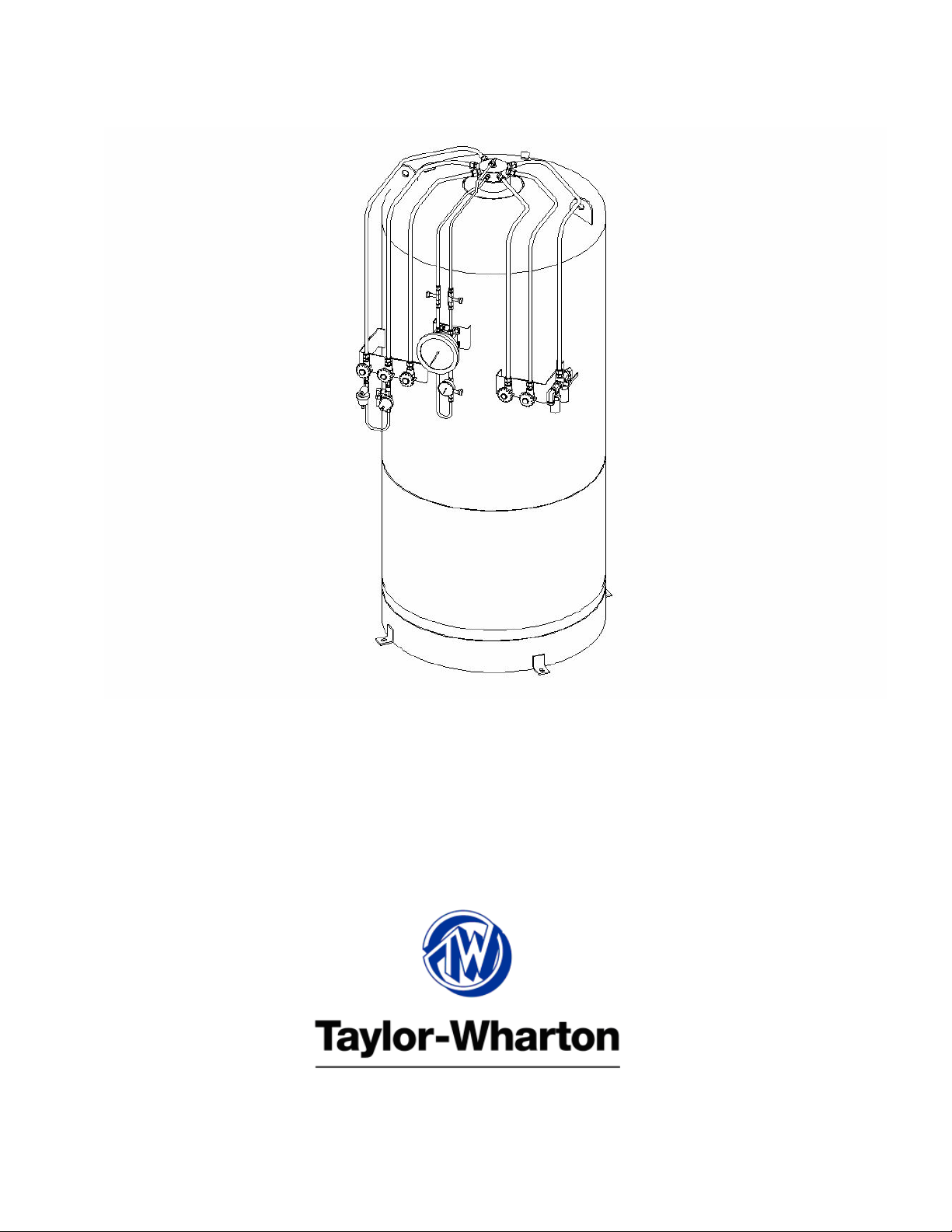
RS-160 & RS-234
Hospital Reserve Tanks
Operation Manual
Product Part Numbers:
RS160C02
RS230C02
Page 2

Do not attempt to use or maintain these units until you read and understand these instructions. Refer to the TaylorWharton’s Safety First
maintain this equipment. If you do not understand these instructions, contact your supplier for additional information.
booklet (TW-202) for handling cryogenic material. Do not permit untrained persons to use or
Table of Contents
WARNING................................................................................................................................................. 2
Safety Precautions for Liquid Nitrogen .................................................................................................................2
Safety Precautions for Liquid Oxygen...................................................................................................................3
WARRANTY AND LIMITATION OF LIABILITY ................................................................................ 5
GENERAL INFORMATION..................................................................................................................... 6
Handling the Container..........................................................................................................................................6
OPERATION.............................................................................................................................................. 7
Component Description .........................................................................................................................................7
Liquid Fill Procedure .............................................................................................................................................8
Withdrawing Product from the Container..............................................................................................................8
Withdrawing Liquid from the Container................................................................................................................9
MAINTENANCE..................................................................................................................................... 10
Regulator Maintenance ........................................................................................................................................10
Instruments...........................................................................................................................................................12
Vacuum................................................................................................................................................................12
Trouble Shooting..................................................................................................................................................14
Replacement Parts................................................................................................................................................15
APPENDIXES..........................................................................................................................................16
RS-160 General Arrangement
RS-234 General Arrangement
1
Page 3

WARNING
The following safety precautions are for your protection. Before performing installation, operating, or maintenance
procedures read and follow all safety precautions in this section and in the referenced publications. Failure to observe
all safety precautions can result in property damage, personal injure, or possibly death. It is the responsibility of the
purchaser of this equipment to adequately warn the user of the precautions and safe practices for the use of this
equipment and the cryogenic fluid stored in it.
Safety Precautions for Liquid Nitrogen
Nitrogen is an inert, colorless, odorless, and tasteless gas that makes up four-fifths of the air you breathe. Liquid
nitrogen is obtained by cooling air until it becomes a liquid and then removing the oxygen that makes up the other fifth
of the air. Liquid nitrogen is at a temperature of -320°F (-196°C) under normal atmospheric pressure.
Extreme Cold - Cover Eyes and Exposed Skin
Accidental contact of liquid nitrogen or cold issuing gas with the skin or eyes may cause a freezing injury similar to
frostbite. Handle the liquid so that it won't splash or spill. Protect your eyes and cover the skin where the possibility
of contact with the liquid, cold pipes and cold equipment, or the cold gas exists. Safety goggles or a face shield should
be worn if liquid ejection or splashing may occur or cold gas may issue forcefully from equipment. Clean insulated
gloves that can be easily removed and long sleeves are recommended for arm protection. Cuffless trousers should be
worn outside boots or over the shoes to shed spilled liquid.
Keep Equipment Area Well Ventilated
Although nitrogen is non-toxic and non-flammable, it can cause asphyxiation in a confined area without adequate
ventilation. Any atmosphere that does not contain enough oxygen for breathing can cause dizziness, unconsciousness,
or even death. Nitrogen being colorless, odorless, and tasteless cannot be detected by the human senses and will be
inhaled normally as if it were air. Without adequate ventilation, the expanding nitrogen will displace the normal air
without warning that a non-life-supporting atmosphere is present. Store liquid containers outdoors or in other well
ventilated areas.
Dispose of Waste Liquid Nitrogen Safely
Dispose of waste liquid nitrogen out-of-doors where its cold temperature cannot damage floors or driveways and
where it will evaporate rapidly. An outdoor pit filled with clean sand or gravel will evaporate liquid nitrogen safely
and quickly.
CAUTION: When installing field fabricated piping, make certain a suitable safety valve is installed in each
section of piping between shut-off valves.
For more detailed information concerning safety precautions and safe practices to be observed when handling
cryogenic liquids consult CGA pamphlet P-12 "Handling Cryogenic Liquids" available from the Compressed Gas
Association, 1235 Jefferson Davis Highway, Arlington, VA 22202.
NOTE: Argon is an inert gas whose physical properties are very similar to those of nitrogen. For handling of liquid
argon, follow the safe practices described for the handling and use of liquid nitrogen.
2
Page 4

Safety Precautions for Liquid Oxygen
Oxygen is a colorless, odorless, and tasteless gas that can be condensed into a liquid at the low temperature of -297°F
(-183°C) under normal atmospheric pressure. Approximately one-fifth of normal air is oxygen. As a liquid, oxygen is
pale blue in color. Oxygen is non-flammable but vigorously accelerates the burning of combustible materials.
Keep Combustibles Away from Oxygen and Eliminate Ignition Sources
Many substances that do not normally burn in air require only a slight spark or moderate heat to set them aflame in the
presence of concentrated oxygen. Other substances that are only moderately combustible in air can burn violently
when a high percentage of oxygen is present.
Do not permit smoking or open flame in any area where liquid oxygen is stored, handled, or used. Keep all organic
materials and other flammable substances away from possible contact with liquid oxygen. Some of the materials that
can react violently with oxygen are oil, grease, kerosene, cloth, wood, paint, tar, and dirt that contains oil or grease.
Under certain conditions flammable materials that have become permeated with liquid oxygen are impact sensitive and
can detonate if subjected to shock.
Keep Area and Exterior Surfaces Clean to Prevent Ignition
As normal industrial soot and dirt can constitute a combustion hazard, all equipment surfaces must be kept very clean.
Do not place oxygen equipment on asphalt surfaces, or allow grease or oil deposits to remain on benches or concrete
surfaces in the vicinity of the oxygen equipment. Use cleaning agents which will not leave organic deposits on the
cleaned surfaces. Equipment to be used in contact with liquid oxygen should be handled only with clean gloves or
hands washed clean of oil.
Maintain Adequate Ventilation
Enclosed areas containing oxygen equipment should be ventilated to prevent accumulations of oxygen and thereby
minimize combustion hazards.
Extreme Cold - Cover Eyes and Exposed Skin
Accidental contact of liquid oxygen or cold issuing gas with the skin or eyes may cause a freezing injury similar to
frostbite. Handle the liquid so that it won't splash or spill. Protect your eyes and cover the skin where the possibility
of contact with the liquid, cold pipes and cold equipment, or the cold gas exists. Safety goggles or a face shield should
be worn if liquid ejection or splashing may occur or cold gas may issue forcefully from equipment. Clean, insulated
gloves that can be easily removed and long sleeves are recommended for arm protection. Cuffless trousers should be
worn outside boots or over the shoes to shed spilled liquid. If clothing should be splashed with liquid oxygen or
otherwise saturated with the gas, air out the clothing immediately, removing it if possible. Such clothing will be highly
flammable and easily ignited while the concentrated oxygen remains, and should not be considered safe for at least 30
minutes.
Replacement Parts Must be Suitable for Oxygen Service
Many materials, especially some non-metallic gaskets and seals, constitute a combustion hazard when in oxygen
service, although they may be acceptable for use with other cryogenic liquids. Make no substitutions for
recommended spare parts. Also, be sure all replacement parts are thoroughly "Cleaned For Oxygen Service" in
accordance with Compressed Gas Association (CGA) Pamphlet G-4.1 "Cleaning for Oxygen Service" or equivalent
industrial cleaning specifications.
Observe Safety Codes When Locating Oxygen Equipment
Before locating oxygen equipment, become thoroughly familiar with National Fire Protection Association (NFPA)
Standard No. 50, "Bulk Oxygen Systems:, and with all federal, state and local safety codes. The NFPA Standard
covers the general principles recommended for the installation of bulk oxygen systems on industrial and institutional
consumer premises.
3
Page 5

CAUTION: When installing field fabricated piping, make certain a suitable safety valve is installed in each
section of piping between shut-off valves.
For more detailed information concerning safety precautions and safe practices to be observed when handling
cryogenic liquids consult CGA pamphlet P-12 "Handling Cryogenic Liquids" available from the Compressed Gas
Association, 1235 Jefferson Davis Highway, Arlington, Va. 22202.
4
Page 6

WARRANTY AND LIMITATION OF LIABILITY
Taylor-Wharton Cryogenics, Harsco Corporation, warrants that the products it furnishes to Buyer hereunder will
conform to specifications (if any) provided in writing by Taylor-Wharton to Buyer and will be free from defects in
materials or workmanship for a period of one year from the date of shipment.
Taylor-Wharton's sole liability upon any claim for breach of warranty or upon any other claim relating to the goods
and/or services provided hereunder is expressly limited to one of the following, to be selected by Taylor-Wharton: (i)
replacement at the agreed point of delivery of any goods found to be defective; (ii) repair of such goods; or (iii) refund,
or crediting to Buyer, the price of such goods; provided that written notice of defect or breach is given by Buyer to
Taylor-Wharton immediately after the defect or alleged breach is discovered and in no event more than twelve (12)
months from delivery and provided further that such goods have not been resold or used beyond the date of discovery
of such defect or alleged breach.
The remedies available to Buyer set forth herein are exclusive remedies, and all other remedies, statutory or otherwise,
are waived by Buyer. Buyer acknowledges that the exclusion of remedies is neither unreasonable nor unconscionable.
Taylor-Wharton may require Buyer to return any defective goods, and failure to return such goods when so requested
will make Buyer liable for payment therefor and will release Taylor-Wharton from any liability hereunder.
Taylor-Wharton will not be liable to Buyer for special, incidental or consequential damages directly or indirectly
arising or resulting from (i) breach of any of the terms set forth in this document, (ii) installation, handling or use of the
goods sold, or (iii) any other cause or claim. In no event will Taylor-Wharton be liable to Buyer for breach of this
agreement or on any other basis in excess of the total amount paid by Buyer hereunder.
THIS WARRANTY IS EXPRESSLY IN LIEU OF ANY OTHER WARRANTIES, EXPRESSED OR IMPLIED,
INCLUDING ANY IMPLIED WARRANTY OF MERCHANTABILITY OR FITNESS FOR ANY PARTICULAR
PURPOSE, AND IS IN LIEU OF ANY OTHER OBLIGATION OR LIABILITY ON THE PART OF TAYLORWHARTON.
5
Page 7

GENERAL INFORMATION
The HOSPITAL RESERVE is a vacuum-insulated, stainless steel container designed to store liquid oxygen, nitrogen,
or argon at cryogenic temperatures. The HOSPITAL RESERVE can be used for on-site storage and supply in a wide
range of applications. Operating pressure for gas service applications is normally 75 psig (5.17 bar). As rugged, long
holding time, gas supply systems, these cylinders are capable of providing continuous flow rates of up to 600 SCFH
(16 Nm
3
/hr). An external vaporizer is required for applications requiring gas at ambient temperatures. Specifications
are provided in the general arrangement drawings in the appendix of this manual.
Handling the Container
The HOSPITAL RESERVE containers are rugged liquid containers. However, all cryogenic liquid containers have an
inner container and outer container with an insulated vacuum space between them. Any abuse (rough handling, dents,
dropping, tip-over, etc.) can affect the integrity of the container's insulation system.
• Never lay the container on its side. Always ship, operate, and store the unit in a vertical, or upright, position.
• When loading or unloading the container from a truck use a forklift, crane, or parallel loading dock.
• Always secure the container to the vehicle before transporting.
• Transport the container empty and at a pressure of 20 psig or less. Never transport the HOSPITAL
RESERVE while containing product.
To move the container over rough surfaces, or to lift the container, attach an appropriate sling to both lifting lugs on
top of the container, and use a portable lifting device that will handle the weight of the container. The weight of the
container is listed in the general arrangement drawing at the end of this manual.
6
Page 8

OPERATION
The HOSPITAL RESERVE tank is designed to store liquefied gas and can deliver either liquid or gas. An external
vaporizer must be used to dispense gas. The following component and piping descriptions are pertinent to the
operation of the container and should be understood before attempting operation. The components may be identified
using the General Arrangement drawings located in the Appendix of this manual.
Component Description
LIQUID WITHDRAWAL Valve (V-2) - Liquid product is withdrawn from the container through the connection
controlled by this valve. The valve is opened for liquid withdrawal after properly connecting to a LIQUID supply line
connection.
LIQUID TOP FILL Valve (V-3) - Liquid product is added to the container through the connection controlled by this
valve.
FULL TRYCOCK & VENT Valve (V-9) - This valve controls a line into the head space of the container. It is used
during the fill process to vent the head space area while liquid is filling the inner container through the LIQUID TOP
FILL (V-3) valve.
PRESSURE GAUGE (G-1) - The pressure gauge displays the internal container pressure.
DIFFERENTIAL PRESSURE GAUGE (LL-2) - The container contents gauge indicates the product level in the
tank. This gauge is a differential pressure gauge calibrated in inches-of-water.
Economizer - An economizer circuit withdraws gas preferentially from the head space over the liquid in the container
-- gas that would otherwise be lost to venting. Excess pressure in the head space of the container is relieved by
allowing gas to flow from this area directly to the vaporizer while product is being withdrawn from the container.
Normal operating pressure is preserved to ensure uninterrupted product delivery. This is controlled by the
ECONOMIZER REGULATOR (R-2). The economizer is automatic and requires no operator attention. The outlet of
the economizer regulator must be piped to the VAPORIZER INLET in order for the circuit to function in this manner.
The economizer may also be used to quietly vent excess pressure to atmosphere without lifting the SAFETY VALVES
(SV-1 & SV-2). See the section below titled, “Withdrawing Product from the Container”.
TANK SAFETY DEVICES - This tank has dual inner container relief devices with a DIVERTER VALVE (V-1) to
allow a reserve set of safety devices to be switched into service while the other is repaired. Each set consists of a
primary relief valve to relieve container pressure when it exceeds a preset point. The valve resets when pressure drops
below this point. In addition, each primary relief valve is backed-up by a secondary relief device which consists of a
rupture disc that will burst at a pressure value that is greater than the primary relief valve setpoint.
The INNER VESSEL SAFETY VALVES (SV-1 & 2) automatically relieve tank pressure when the maximum
allowable working pressure of the tank is reached. The INNER RUPTURE DISCS (BD-1 & 2) are the secondary relief
devices that rupture and require replacement of inserts in the event a safety valve malfunctions and allows tank
pressure to reach the burst pressure rating. Like the primary relief valves, one rupture disc is in service while the other
is in reserve.
Overpressure of the annular space of the container is protected by an ANNULAR RUPTURE DISC (BD-3).
Pressure Building - A Pressure Building circuit is used to ensure sufficient driving pressure during high product
withdrawal periods. This function is actuated by opening a valve that creates a path from the liquid in the bottom of the
container to the gas space in the top. This path contains a pressure building coil to vaporize product as it migrates from
7
Page 9

the bottom to the top of the tank. When the pressure building valve is open, and the container pressure falls below the
pressure building regulator setting, liquid is expanded to a gas and pressurizes the space of the inner container.
Pressure building is not normally required unless container pressure drops below the gas output pressure desired.
PRESSURE BUILDING INLET VALVE (V-5) - allows liquid product from the inner container into the pressure
building system. It is normally used to turn the pressure building function on and off.
PRESSURE BUILDING REGULATOR (R-1) - automatically controls flow through the circuit to maintain tank
pressure to its preset value of 75 psig (5.2 bar).
PRESSURE BUILDING ISOLATION VALVE (V-4) - serves as the outlet for the pressure building circuit and the
inlet to the ECONOMIZER REGULATOR (R-2) and the economizer circuit. Although closing the valve will defeat
both circuit functions, this valve's function is to allow isolation of circuit components for repair. The PRESSURE
BUILDING RELIEF VALVE (RV-3) will relieve pressure buildup from trapped liquid between the pressure
building regulator and the inlet valve.
Liquid Fill Procedure
WARNING: Filling operations should take place only in well-ventilated areas. Accumulations of product gas can
be very dangerous (refer to the safety precautions in the front of these instructions). Maintain
adequate ventilation at all times.
1. Remove protective caps from fill and vent connections. Close all valves.
2. Connect fill hose to the LIQUID TOP FILL (V-3) connection.
3. Check that fill hose blow-down valve on storage unit is closed.
4. Open supply valve on the bulk storage source, and the LIQUID TOP FILL (V-3) valve and FULL
TRYCOCK & VENT (V-9) valve on the unit to be filled.
NOTE: When the fill is started, venting will vary rapidly as considerable amounts of liquid are vaporized in
cooling the lines and the tank. When the lines are cooled to liquid temperature, vapor flow will be
reduced and it will be necessary to partially close the FULL TRYCOCK & VENT (V-9) valve to
maintain the required saturation pressure.
5. When liquid appears from the full-trycock line, first close the LIQUID TOP FILL (V-3) valve, and then the
FULL-TRYCOCK & VENT (V-9) valve.
6. Close the bulk storage source supply valve, immediately open the hose blow-down valve to prevent rapid
pressure buildup in the filling line.
7. Disconnect the fill hose.
8. Close the hose blow-down valve.
Withdrawing Product from the Container
To withdraw gas from the HOSPITAL RESERVE, connect a suitable vaporizer to the VAPORIZER INLET VALVE
(V-2). A properly sized relief valve must be installed on the vaporizer. Follow the vaporizer manufacturer’s
recommendation for the proper relief valve. A suitable pressure regulator should be installed downstream of the
vaporizer. Connect the output of the regulator to the application. Open the VAPORIZER INLET VALVE (V-2) and
8
Page 10

both pressure building valves (V-4 & 5). When the container pressure reaches 75 psig (5.2 bar), set the output pressure
regulator for the desired delivery pressure.
On most installations the outlet of the economizer regulator (R-2) should be piped to the inlet of the vaporizer. This
will help conserve product. See the explanation of the economizer in the component description section.
On some installations it may be desirable to allow the economizer regulator (R-2) to vent to atmosphere. This will
prevent pressure from ever building high enough to lift the safety valves (SV-1 & SV-2). The liquid inside the tank
will remain colder and the venting noise of the safety valves will be avoided.
Withdrawing Liquid from the Container
Attach a transfer hose to the connection labeled VAPORIZER INLET and open the adjacent LIQUID
WITHDRAWAL (V-2) valve. The pressure in the container will drive liquid product out through the valve as long as
the container pressure exceeds that of the receiver. The rate of liquid withdrawal from these containers is variable
depending on the container pressure and the saturation temperature of the liquid.
CAUTION: To avoid contamination, close the LIQUID WITHDRAWAL (V-2) valve on an empty container
before disconnecting the transfer line. Protect hose ends. Moisture will condense within a cold open
hose and will be carried to equipment during the next use.
9
Page 11

MAINTENANCE
Read the Safety Precautions in the front of this manual before attempting any repairs on these containers. Also follow
these additional safety guidelines while performing container maintenance.
Never work on a pressurized container. Open the vent valve as a standard practice during maintenance to
guard against pressure build-up from residual liquid.
Use only repair parts cleaned for oxygen service. Be certain your tools are free of oil and grease. This is a
good maintenance practice, and helps ensure you do not create a combustion hazard when working on
containers for oxygen service.
Leak test connections after every repair. Pressurize the container with an appropriate inert gas for leak
testing. Use only approved leak test solutions and follow the manufacturer's recommendations. "Snoop"
Liquid Leak Detector is one approved solution, it is available from: Nupro co. 4800 E. 345th St. Willoughby,
Ohio 44094
CAUTION: In oxygen sy stems, residue of leak detector solutions can be flammable. All surfaces to which the
leak detector solutions have been applied must be adequately rinsed with potable water to remove all
traces of residue. Reference CGA G-4.4 Section 4.9.
Regulator Maintenance
Single stage, spring loaded regulators are employed in the pressure building and economizer circuits. These regulators
can be adjusted on the container, replaced, or checked and adjusted off the container in a readily fabricated bench
adjustment fixture.
Pressure Building Regulator Adjustment - On Container
1. Fill the container with the appropriate liquid product.
2. Open the PRESSURE BUILDING VALVE (V-5) and allow the container pressure to stabilize for about an
hour. Note the point where the pressure stabilizes.
3. Adjust the screw on the top of the PRESSURE BUILDING REGULATOR (R-1) to raise or lower the
pressure to the desired point. When decreasing the setting, the pressure building valve must be closed and the
container vented to a lower pressure. Then repeat step 2 in order to observe the change.
Note: The range of adjustment is 50 to 150 psig (3.5 to 10.3 bar). Do not attempt to set the regulator to a pressure
outside of its design range.
Pressure Building Valve Removal or Replacement Procedure
1. Close the ISOLATION VALVE (V-4) and the PRESSURE BUILDING VALVE (V-5).
2. Loosen the tube connection nut on the output side of the regulator. Allow pressure to completely bleed from
the tube. Remove the tube.
3. Remove the regulator from the container by unscrewing the valve body from the nipple at the input side.
4. Repair the regulator and adjust its setpoint using the bench test setup.
10
Page 12

5. Clean thread sealant from threads of nipple and regulator. To install a replacement or readjusted regulator,
apply Teflon tape to the nipple on the container and thread the valve body onto the nipple.
6. Reconnect the tube connection to the regulator and tighten.
7. Open the ISOLATION VALVE (V-4) and the PRESSURE BUILDING VALVE (V-5) and check for leaks.
Regulator Adjustment (P.B. or Economizer) - Bench Procedure
For more accurate adjustment it is recommended that the pressure building regulator be removed from the system. A
regulator bench adjustment fixture should be used. The figure below shows a typical setup.
Pressure
Gauge
Pressure
Gauge
High Pressure
Cylinder
On/Off
Valve
Regulator
Regulator to
be adjusted
Dump Valve
Regulator bench adjustment fixture.
1. Leak test joints between the high pressure cylinder regulator and the dump valve. Joints must be leak free
before proceeding.
2. Close the on/off valve and the dump valve.
3. Open the high pressure cylinder valve.
4. Set the high pressure regulator above the desired set point for the pressure builder.
5. Slowly open the on/off valve and observe the downstream pressure gauge.
6. When the regulator under adjustment closes, the P.B. set point is indicated on the downstream pressure
gauge.
7. Close the on/off valve and open the dump valve.
8. To reset the regulator, loosen the lock nut on the adjusting screw. Raise the setpoint by turning the
adjusting screw clockwise; lower the setpoint by turning the screw counterclockwise. After adjustment,
repeat steps 5 and 6 to check the setting before reinstalling the regulator on the liquid container.
9. When reinstalling the pressure building regulators on the system, orient the regulator so the flow arrow points
away from the pressure building valve (V-5).
Economizer Regulator Adjustment Procedure
Adjustment of the economizer regulator may be accomplished with the regulator removed from the system. The
regulator bench adjustment fixture shown above should be used.
11
Page 13

1. Leak test joints between the high pressure cylinder regulator and the dump valve. Joints must be leak free
before proceeding.
2. Close the on/off valve. Open the dump valve.
3. Open the high pressure cylinder valve.
4. Set the high pressure regulator above the desired set point for the economizer.
5. Slowly open the on/off valve for a few seconds and then close it.
6. When the regulator under adjustment closes, the economizer set point is indicated on the upstream
pressure gauge.
7. To reset the regulator, loosen the lock nut on the adjusting screw. Raise the setpoint by turning the
adjusting screw clockwise; lower the setpoint by turning the screw counterclockwise. After adjustment,
repeat steps 5 and 6 to check the setting before reinstalling the regulator on the liquid container.
Note: The range of adjustment is 75 to 175 psig (5.2 to 12.1 bar). Do not attempt to set the regulator to a pressure
outside of its design range.
Note: Both regulators have directional gas flow. The arrow on the regulator body must point in direction indicated
in the Bench Adjustment Fixture illustration.
Economizer Valve Removal/Installation
1. Close the ISOLATION VALVE (V-4) and the PRESSURE BUILDING VALVE (V-5).
2. Loosen the tube connection nut below the ECONOMIZER REGULATOR (R-2). Allow pressure to
completely bleed from the tube. Remove the tube.
3. Remove the regulator from the container by loosening the tube connection nut above the regulator.
4. Repair the regulator or adjust its setpoint using the bench test setup.
5. Reconnect the tube connections to the regulator and tighten.
6. Open the ISOLATION VALVE (V-4) and the PRESSURE BUILDING VALVE (V-5) and check for leaks.
Instruments
User adjustment of the pressure gauge or liquid level gauge is not possible. If the gauges are malfunctioning, they
must be replaced. Close both isolation valves (V-6 and V-7) and immediately open the equalization valve (V-8).
Loosen one of the tube compression fitting nuts to reduce pressure. When the pressure gauge (G-1) indicates zero it is
safe to work on the circuit.
Vacuum
Cryogenic containers are two containers, one within the other. The space between the containers acts as a highly
efficient thermal barrier including high technology insulation, a vacuum, and a vacuum maintenance system. Each
serves a very important part in the useful life of the container. The high technology insulation is very effective in
12
Page 14

preventing radiated heat from entering the inner container. Unfortunately, the perfect vacuum cannot be achieved
since trace gas molecules begin to enter the vacuum space from the moment of manufacture. The vacuum
maintenance system consists of materials that gather trace gas molecules from the vacuum space. The maintenance
system can perform its function for years, however it has a limited capacity. When the vacuum maintenance system
becomes saturated it can no longer maintain the vacuum integrity of the container. The change will be very gradual
and may go unnoticed for several years. When the vacuum in the insulation space is no longer effective, the following
symptoms may appear:
1. With liquid in the container, the outer casing will be much colder than comparative containers.
2. Frost, indicating the liquid level, may be visible on the outer casing of the container.
3. Condensation may form on the container. Note that some icing or condensation is normal around the
piping connections of the vessel. Condensation may also occur on the vessel outer surface as a result of
high humidity.
4. The relief valve will open continuously until the container is empty.
If it has been determined that the vessel has a vacuum problem it will be necessary to repair and re-evacuate the vessel.
A skilled service technician should perform vessel repair. Contact Taylor-Wharton customer service at 1-800-8982657 for assistance in locating the closest service center.
13
Page 15

Trouble Shooting
The following chart is provided to give you some guidance in determining the probable cause and suggested corrective
action for some problems that may occur with cryogenic liquid containers.
TROUBLE SHOOTING CHART
Symptom Possible Cause Corrective Action
1. Consistently low operating
pressure
2. No pressure shown on gauge. a. Bad Pressure Gauge.
3. Container is cold and may have ice
or frost on outer casing. Will not
hold liquid overnight. Relief valve
is venting gas.
4. Ice formation on bottom of
container when P.B. valve is
closed.
a. Relief valve open at low pressure.
b. Economizer valve stuck open.
c. P.B. valve closed.
d. Defective P.B. regulator.
e. Leaks in valves or plumbing.
b. Open inner container safety head.
c. Leaks in valves or plumbing.
d. Empty tank.
a. Vacuum loss. Check outer casing
bursting disc.
b. Defective/leaking pressure
building regulator.
a. Pressure building hand valve not
closed properly.
a. Remove and replace relief valve.
b. Remove and replace economizer
valve.
c. Open P.B. Valve.
d. Adjust or replace regulator.
e. Leak test and repair leaks.
a. Remove and replace bad gauge.
b. Remove and replace safety head.
Pressurize container and check
relief operation.
c. Leak test and repair leaks.
d. Fill tank.
a. Consult with Taylor-Wharton for
course of action. Do not attempt
to put additional liquid in
container.
b. Repair or replace regulator.
a. Replace valve.
5. Container vents through the relief
valve when in use.
a. Pressure building regulator set
above relief valve setting.
b. Economizer valve not functioning.
c. Poor vacuum.
14
a. Remove and reset or replace
regulator.
b. Repair or replace valve.
c. Consult with Taylor-Wharton for
course of action.
Page 16

Replacement Parts
When placing orders, please use the nomenclature and part numbers in this section. The parts may be
identified using the component tag numbers or the flow schematic on the general arrangement drawings
located in the appendix of this manual. Send written orders to:
Taylor-Wharton fax: 251-443-2250,
4075 Hamilton Blvd. Call: 251-443-8680
Theodore, AL 36582 or, 1-800-868-2657
RS-160 Replacement Parts
Tag Number Part Number Description
V-1 85449401 VALVE, 3 WAY DIVERTER, 1/2" NPT, BRASS
V-2, 3, 4, 5, & 9 6914-4050 VALVE, 1/2" NPT, REGO, BRASS
V-6 & 7 85443649 GLOBE VALVE, 1/4" MNPT X 1/4" FNPT, BRASS
V-8 85443770 GLOBE VALVE, 1/4" FNPT, BRASS
BD-1 & 2 M6009C033 SAFETY HEAD, 356 PSIG, 1/2" NPT, BRASS
BD-3 BC04-6C66 CASING RUPTURE DISC
G-1 57143490 PRESSURE GAUGE, 400 PSIG, 2-1/2" DIAMETER
LL-2 57408705 INDICATOR, PRESSURE, DIFFERENTIAL, 0-80 INCHES OF WATER
R-1 85362602 PB REGULATOR, 1/4" NPT, 75 PSIG
R-2 85362603 ECONOMIZER, 1/4" NPT, 135 PSIG
RV-1 6913-9071 RELIEF VALVE, 350 PSIG X 1/4" NPT
SV-1 & 2 85440299 ASME RELIEF VALVE, 250 PSIG X 1/2" NPT BRASS
N/A RS169C25 FLOW SCHEMATIC
RS-234 Replacement Parts
Item No. Part Number Description
V-1 85449401 VALVE, 3 WAY DIVERTER, 1/2" NPT, BRASS
V-2, 3, 4, 5, & 9 6914-4050 VALVE, 1/2" NPT, REGO, BRASS
V-6, 7, & 8 85443725 VALVE, 1/4" MNPT, BRASS
BD-1 & 2 M6009C033 SAFETY HEAD, 356 PSIG, ½" NPT, BRASS
BD-3 BC04-6C66 CASING RUPTURE DISC
G-1 57143490 PRESSURE GAUGE, 400 PSIG, 2.5" DIAMETER
LL-2 57408705 INDICATOR, PRESSURE, DIFFERENTIAL, 0-80 IN.
R-1 85362602 PB REGULATOR, 1/4" NPT, 75 PSIG
R-2 85362603 ECONOMIZER, 1/4" NPT, 135 PSIG
RV-1 6913-9071 RELIEF VALVE, 350 PSIG X 1/4" NPT
SV-1 & 2 85440299 ASME RELIEF VALVE, 250 PSIG X 1/2" NPT BRASS
N/A RS169C25 FLOW SCHEMATIC
15
Page 17

APPENDIXES
Appendix 1 - RS-160 General Arrangement
Appendix 2 - RS-234 General Arrangement
16
Page 18

4075 Hamilton Blvd.
Theodore, Alabama 36582 U.S.A.
Telephone (251) 443-8680
Fax (251) 443-2250
In U.S. and Canada: (800) TW TANKS (898-2657)
Manual P/N 99187407 Publication # BT-407 Revision A
 Loading...