

Page 1
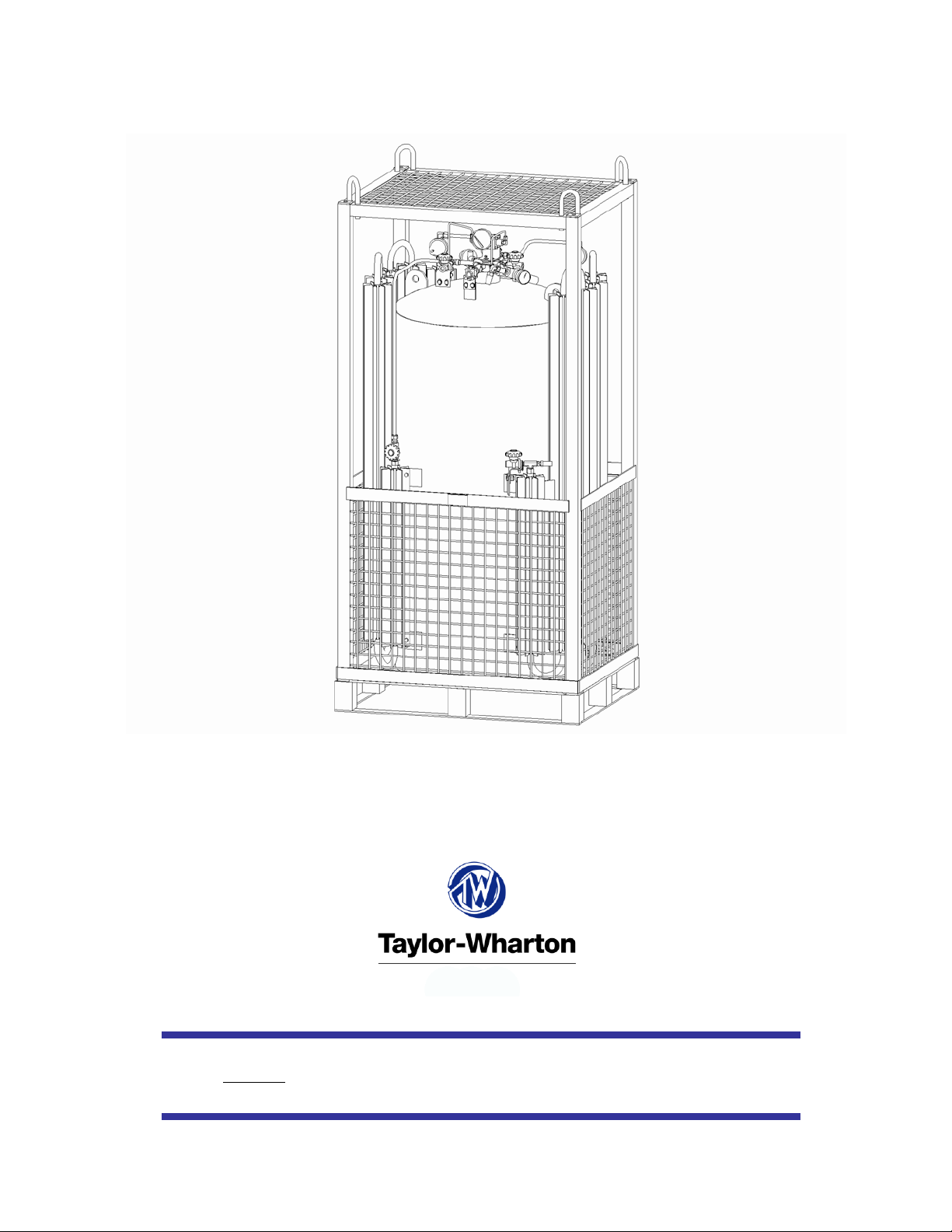
Laser Pak III
Part Number LP3000
Do not attempt to use or maintain these units until you read and understand these instructions. Refer to the TaylorWharton’s Safety First
aintain this equipment. If you do not understand these instructions, contact your supplier for additional information. m
booklet (TW-202) for handling cryogenic material. Do not permit untrained persons to use or
Page 2

Table of Contents
WARNING 3
Safety Precautions for Liquid Oxygen 3
Safety Precautions for Liquid Nitrogen 4
INTRODUCTION 5
System Description 5
PIPING CIRCUITS 6
Fill and Vent Circuits 7
Express Fill Circuit 8
Pressure Building Circuit 9
Gas Withdrawal Circuit 10
Economizer Circuit 11
Safety Devices 12
Instrumentation Circuits 13
OPERATION 14
Receiving Inspection 14
Handling 14
Determining Proper Fill Weight 14
Filling by Pressure Transfer 14
Filling by Pump Transfer 15
Withdrawing Gas 15
Withdrawing Liquid 16
Changing Gas Service 16
MAINTENANCE 17
Leak Test 17
Globe Valves 17
Regulators 18
Instruments 19
Checking Vacuum 19
Trouble-Remedy Guide 21
Replacement Parts 22
APPENDIXES 23
Laser Pak III General Arrangement
Page 3

WARNING
The following safety precautions are for your protection. Before installing, operating, or maintaining this unit
read and follow all safety precautions in this section and in reference publications. Failure to observe all
safety precautions can result in property damage, personal injury, or possibly death. It is the responsibility of
the purchaser of this equipment to adequately warn the user of the precautions and safe practices for the use of
this equipment and the cryogenic fluid stored in it.
CAUTION: When installing field fabricated piping, make certain a suitable safety valve is installed in
each section of piping between shut-off valves.
For more detailed information concerning safety precautions and safe practices to be observed when handling
cryogenic liquids consult CGA pamphlet P-12 "Handling Cryogenic Liquids" available from the Compressed
Gas Association, 1235 Jefferson Davis Highway, Arlington, VA 22202.
Safety Precautions for Liquid Oxygen
Oxygen is a colorless, odorless, and tasteless gas that can be condensed into a liquid at the low temperature of
297 degrees below zero Fahrenheit (-183°C) under normal atmospheric pressure. Approximately one-fifth of
normal air is oxygen. As a liquid, oxygen is pale blue in color. Oxygen is non-flammable, however it
vigorously accelerates the burning of combustible materials.
Keep Combustibles Away from Oxygen and Eliminate Ignition Sources
Many substances that do not normally burn in air require only a slight spark or moderate heat to set them
aflame in the presence of concentrated oxygen. Other substances, which are only moderately combustible in
air, can burn violently when a high percentage of oxygen is present.
Do not permit smoking or open flame in any area where liquid oxygen is stored, handled, or used. Keep all
organic materials and other flammable substances away from possible contact with liquid oxygen. Some of
the materials that can react violently with oxygen are oil, grease, kerosene, cloth, wood, paint, tat, and dirt that
contains oil or grease. Under certain conditions flammable materials that have become permeated with liquid
oxygen are impact sensitive and can detonate if subjected to shock.
Keep Area and Exterior Surfaces Clean to Prevent Ignition
As normal industrial soot and dirt can constitute a combustion hazard, all equipment surfaces must be kept
very clean. Do not place oxygen equipment on asphalt surfaces, or allow grease or oil deposits to remain on
benches or concrete surfaces in the vicinity of the oxygen equipment. Use cleaning agents, which will not
leave organic deposits, on the cleaned surfaces. Equipment to be used in contact with liquid oxygen should be
handled only with clean gloves or hands washed clean of oil.
Maintain Adequate Ventilation
Enclosed areas containing oxygen equipment should be ventilated to prevent accumulations of oxygen and
thereby minimize combustion hazards.
Extreme Cold - Cover Eyes and Exposed Skin
Accidental contact of liquid oxygen or cold issuing gas with the skin or eyes may cause a freezing injury
similar to frostbite. Handle the liquid so that it won't splash or spill. Protect your eyes and cover the skin
where the possibility of contact with the liquid, cold pipes and equipment, or the cold gas exists. Safety
goggles or a face shield should be worn if liquid ejection or splashing may occur or cold gas may issue
forcefully from equipment. Clean, insulated gloves that can be easily removed and long sleeves are
recommended for arm protection. Cuffless trousers should be worn outside boots or over the shoes to shed
3
Page 4

spilled liquid. If clothing should be splashed with liquid oxygen or otherwise saturated with the gas, air out
the clothing immediately, removing it if possible. Such clothing will be highly flammable and easily ignited
while the concentrated oxygen remains, and should not be considered safe for at least 30 minutes.
Replacement Parts Must be Suitable for Oxygen Service
Many materials, especially some non-metallic gaskets and seals, constitute a combustion hazard when in
oxygen service, although they may be acceptable for use with other cryogenic liquids. Make no substitutions
for recommended spare parts. Also, be sure all replacement parts are thoroughly "Cleaned For Oxygen
Service" in accordance with Compressed Gas Association (CGA) Pamphlet G-4.1 "Cleaning for Oxygen
Service" or equivalent industrial cleaning specifications.
Observe Safety Codes When Locating Oxygen Equipment
Before locating oxygen equipment, become thoroughly familiar with National Fire Protection Association
(NFPA) Standard No. 50, "Bulk Oxygen Systems", and with all federal, state and local safety codes. The
NFPA Standard covers the general principles recommended for the installation of bulk oxygen systems on
industrial and institutional consumer premises.
Safety Precautions for Liquid Nitrogen
Nitrogen is an inert, colorless, odorless, and tasteless gas making up four-fifths of the air you breathe. Liquid
nitrogen is obtained by cooling air until it becomes a liquid and then removing the oxygen. Air is roughly
one-fifth oxygen. Liquid nitrogen is at a temperature of -320°F (-196°C) under normal atmospheric pressure.
Extreme Cold - Cover Eyes and Exposed Skin
Accidental contact of liquid nitrogen or cold issuing gas with the skin or eyes may cause a freezing injury
similar to frostbite. Handle the liquid so that it won't splash or spill. Protect your eyes and cover the skin
where the possibility of contact with the liquid, cold pipes and equipment, or the cold gas exists. Safety
goggles or a face shield should be worn if liquid ejection or splashing can occur or cold gas can issue
forcefully from equipment. Insulated gloves that can be easily removed and long sleeves are recommended
for arm protection. Trousers without cuffs should be worn outside boots or over the shoes to shed spilled
liquid.
Keep Equipment Area Well Ventilated
Although nitrogen is non-toxic and non-flammable, it can cause asphyxiation in a confined area without
adequate ventilation. Any atmosphere not containing enough oxygen for breathing can cause dizziness,
unconsciousness, or even death. Nitrogen, a colorless, odorless, and tasteless gas, cannot be detected by the
human senses and will be inhaled normally as if it were air. Without adequate ventilation, the expanding
nitrogen will displace the normal air resulting in a non-life-supporting atmosphere.
Dispose of Waste Liquid Nitrogen Safely
Dispose of waste liquid nitrogen out-of-doors where its cold temperature cannot damage floors or driveways
and where it will evaporate rapidly. An outdoor pit filled with clean sand or gravel will evaporate liquid
nitrogen safely and quickly.
NOTE: Argon is an inert gas whose physical properties are very similar to those of nitrogen. For
handling of liquid argon, follow the safe practices described for the handling and use of liquid nitrogen.
4
Page 5

INTRODUCTION
This manual provides information for the operation and maintenance of Taylor-Wharton's Laser Pak III
transportable cryogenic gas supply system. The Laser Pak III is designed for applications requiring nitrogen,
argon, or oxygen gas at pressures and flow-rates higher than possible with traditional pallet base cryogenic
vessels. The Laser Pak III is capable of delivering gas at a continuous rate of 2,000 standard cubic feet per
hour while maintaining a supply pressure exceeding 350 psig. Gas delivery rates of 3,000 standard cubic feet
per hour are possible during intermittent use.
Product specifications, flow diagram, views, and important dimensions are shown on the general arrangement
drawing provided in the appendix of this manual.
System Description
The Laser Pak III consists of a cryogenic liquid vessel, piping, vaporizer, and a patented high capacity
pressure builder. The product is mounted on a galvanized steel pallet for easy handling by forklift. A
galvanized steel frame encompasses the unit and protects it during transport.
A 393 liter liquid capacity (437 liter gross capacity) cryogenic vessel is included in the system. The vessel
consists of a pressure vessel suspended inside a jacket. The space between the pressure vessel and the jacket
is evacuated and insulated with a micro-fiberglass / aluminum foil radiation shield. Both the inner pressure
vessel and vacuum jacket are constructed of type 304 stainless steel. The vessel is designed and constructed in
accordance with DOT-4L and may be legally transported by truck in the United States while containing
product.
Piping circuits allow the vessel to vent, fill, pressurize, and provide pressurized gas. Piping is type-304
stainless steel. Valves are brass. Fittings are machined from forged brass or type-316 stainless steel. The
vaporizer and pressure builder are constructed of aluminum.
Instrumentation consists of a pressure gauge and a differential pressure gauge. The pressure gauge allows the
vessel pressure to be monitored. Accurate measurement of the vessel contents is provided by the differential
pressure gauge.
The Laser Pak III pressurizes cryogenic liquid by adding heat to the liquid in a controlled fashion. All energy
for building pressure is provided by heat from ambient air. The pressure builder design is protected by United
States Patent Number 6,276,143.
5
Page 6
PIPING CIRCUITS
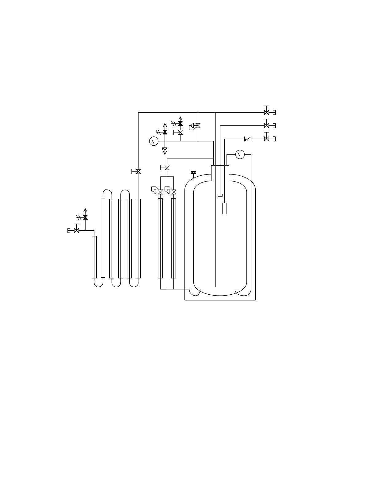
The following paragraphs describe the operation of the piping circuits of the system. The descriptions refer to
the main components of each circuit and are grouped by function. Reference the piping schematic below and
in the general arrangement drawing for the component designations. These component and circuit
descriptions should be understood before attempting operation.
SV-1
SV-3
PVC-2
-
PI-1
V-2
PVC-1
VC-1
-
V-3
R-2
PVC-1
CV-1
LI-1
V-7
V-4
-
-
CN-1
SV-2
FSV-1
CN-2
V-5
PBC-1
Legend
CN-1 Pump / Top Fill Connection SV-2 Safety Valve, 500 psig
CN-2 Gas Withdrawal Connection SV-3 Safety Valve, 22 psig
CN-3 Vent / Trycock Connection V-1 Valve, Pump / Top Fill
CN-4 Liquid Connection V-2 Valve, Vaporizer Isolation
LI-1 Liquid Level Gauge V-3 Valve, Pressure Building
PI-1 Pressure Gauge V-4 Valve, Vent / Trycock
PBC-1 Pressure Building Coil V-5 Valve, Gas Withdrawal
PVC-1 Pressure Building Regulator V-6 Valve, Isolation
PVC-2 Economizer Regulator V-7 Valve, Liquid
R-1 Safety Disc VC-1 Vaporizer Coil
R-2 Outer Casing Safety Disc FSV-1 Fill Stop Valve
SV-1 Safety Valve, 500 psig CV-1 Pump / Top Fill Check Valve
Figure 1: System Piping Schematic
6
Page 7
Fill and Vent Circuits
The liquid valve (V-7) communicates with the bottom of the vessel. A stainless steel tag labeled “LIQUID”
identifies the valve and the liquid connection (CN-4). Liquid is added or removed from the vessel through
this connection and valve.
The vent / trycock valve (V-4) is attached to a vertical tube in the upper portion of the vessel. The open end of
the tube is positioned at 90% liquid level based on the vessel volume. Opening the vent valve reduces
pressure in the vessel during filling. It also severs as a “full trycock”, venting liquid from the vessel when the
liquid level exceeds 90%. A tag labeled “VENT” is attached to this valve.
V-7
CN-4
V-4
CN-3
Figure 2: Fill and vent circuits highlighted in blue.
(Frame omitted from view for clarity.)
7
Page 8
Express Fill Circuit
The Express Fill circuit may be used for filling from the Taylor-Wharton Express Truck or for top filling by a
cryogenic pump. The pump / top fill valve (V-1) is a quarter-turn ball valve permitting filling of the vessel. A
check valve (CV-1) prevents product from escaping should the pump / top fill valve be opened inadvertently.
A fill stop valve (FSV-1) within the vessel prevents over filling. This device functions when filled by the
Taylor-Wharton Express Truck in automatic fill mode. The fill stop valve will not function when the vessel is
filled by a typical cryogenic pump.
CV-1
V-1
CN-1
Figure 3: Express Fill circuit highlighted in blue.
(Frame omitted from view for clarity.)
8
Page 9

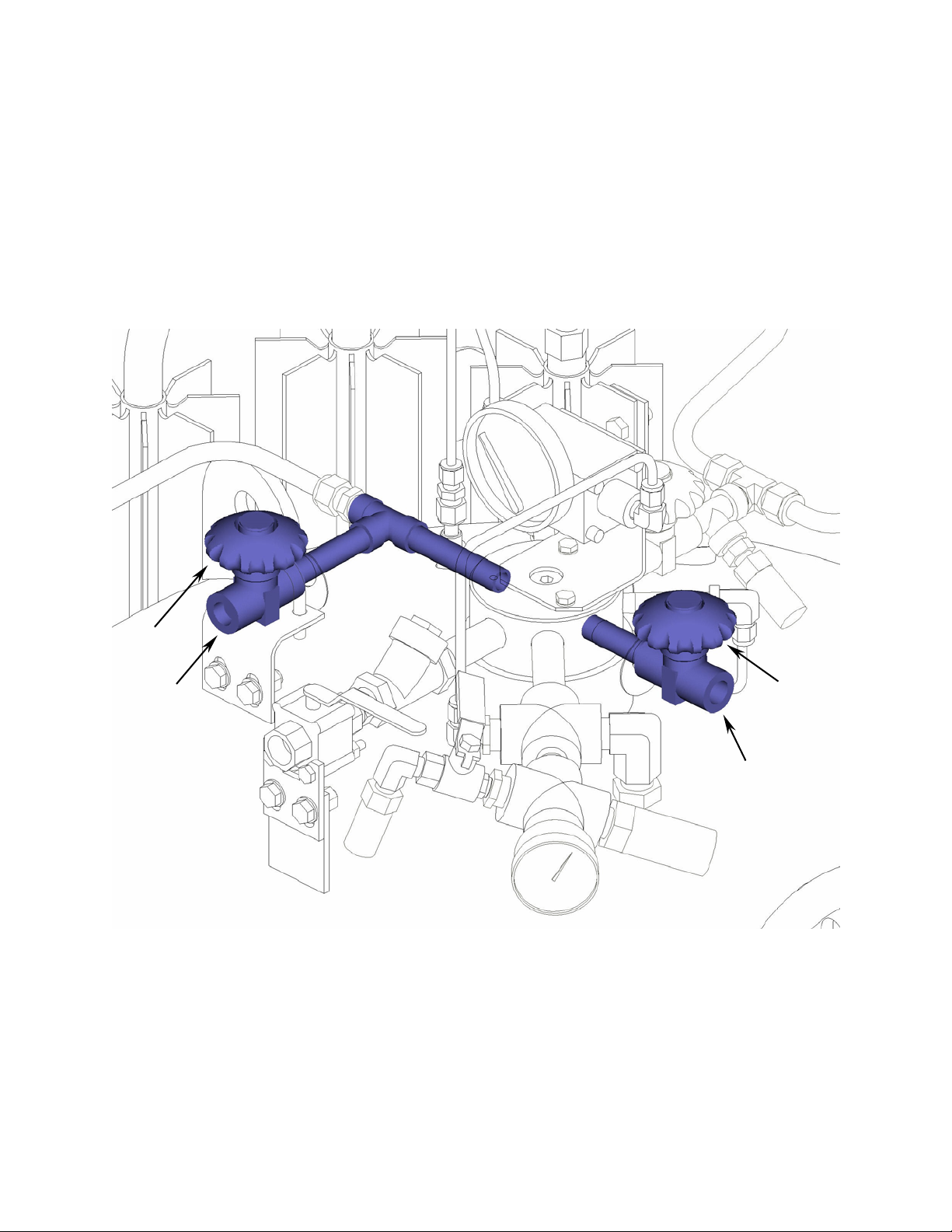
Pressure Building Circuit
The pressure building circuit serves to build pressure after filling the vessel. The circuit is also used to ensure
sufficient driving pressure during high product withdrawal periods. Opening the pressure building circuit
valve (V-3) permits the circuit to function. A stainless steel tag labeled “P.B.” is attached to the valve. When
the pressure inside the vessel drops below 450 psig, the pressure building regulators (PVC-1) begin to open.
Two pressure building regulators are used to maximize performance. The regulators open fully at 400 psig.
This creates a path from the liquid in the bottom of the container to the gas space in the top. This path
contains a pressure building coil (PBC-1) to vaporize product as it flows from the bottom to the top of the
vessel. Liquid is expanded to a vapor and pressure is increased in the vessel. This pressure building circuit
design is protect by United States Patent Number 6,276,143.
PVC-1
PBC-1
V-3
PVC-1
PBC-1
Figure 4: Back-view showing the pressure building circuit highlighted in blue.
(Frame omitted from view for clarity.)
9
Page 10

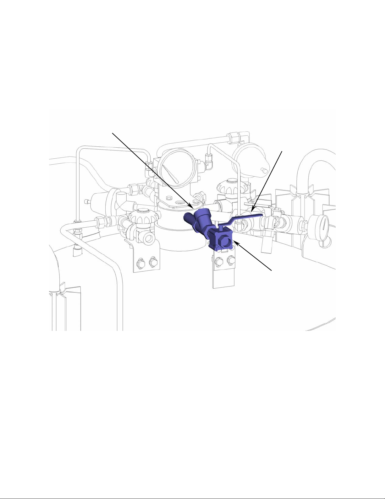
Gas Withdrawal Circuit
The gas withdrawal circuit vaporizes cryogenic liquid and warms it to ambient temperatures for use in the
final application. Opening the gas withdrawal valve (V-5) allows liquid, driven by the pressure within the
vessel, to flow through the vaporizer (VC-1). The vaporizer uses heat from the ambient air to convert the
liquid into a gas and warm it. Should the vaporizer be damaged or require repair the vaporizer isolation valve
(V-2) may be closed to prevent loss of product. The vaporizer safety valve (SV-2) prevents excessive
pressure build-up should the gas withdrawal valve and vaporizer isolation valve be closed while the vaporizer
contains liquid or cold gas.
VC-1
V-2
VC-1
SV-2
V-5
CN-2
Figure 5: Gas withdrawal circuit highlighted in blue.
(Frame omitted from view for clarity.)
10
Page 11

Economizer Circuit
The economizer circuit reduces product loss due to normal evaporation of the liquid within the vessel. The
economizer regulator (PVC-2) opens when the pressure within the vessel exceeds 475 psig. This allows gas
from the top of the vessel to flow into the vaporizer circuit. Provided that gas from the vaporizer is being
withdrawn for use, the vessel pressure will be reduced. The primary safety valve (SV-1) will be prevented
from opening, avoiding product loss.
PVC-2
Figure 6: Economizer circuit highlighted in blue.
(Frame omitted from view for clarity.)
11
Page 12

Safety Devices
R
The Laser Pak III features relief devices to prevent over pressurization of the vessel, piping, and vaporizers. A
primary relief valve (SV-1) relieves pressure when it exceeds 500 psig. The valve reseats when pressure
drops below this point. In addition, the primary relief valve is supported by a secondary relief device
consisting of a rupture disc (R-1) that will burst at a pressure of approximately 750 psig. The rupture discs
require replacement in the event a safety valve malfunctions and allows vessel pressure to reach the burst
pressure rating.
A relief valve (SV-3), set to open at 22 psig, is also provided. Closing the isolation valve (V-6) prevents flow
through the relief valve. This feature is useful if it is necessary to transport the Laser Pak III at a reduced
pressure. It also allows liquid to be stored at a low pressure. Cryogenic liquid stored at low pressure is colder
and therefore more dense than liquid stored at higher pressure. Dense liquid maximizes the pressure builder
performance for high flow applications.
SV-3
V-6
Figure 7: Safety circuit highlighted in blue.
(Frame and wiring omitted from view for clarity.)
12
-1
SV-1
Page 13

Instrumentation Circuits
The instrumentation consists of a pressure gauge and differential pressure gauge. The pressure gauge (PI-1)
displays the inner vessel pressure in pounds-per-square-inch and kilopascals. The differential pressure gauge
measures the difference in pressure between the top and bottom of the vessel. Product within the vessel
creates a higher pressure at the bottom of the vessel than at the top. Readings on the differential pressure
gauge are in inches of water. This reading, when compared to the contents chart attached to the front of the
vessel, allows accurate monitoring of the amount of product within the vessel.
LI-1
Figure 8: Instrumentation circuits highlighted in blue.
(Frame omitted from view for clarity.)
PI-1
13
Page 14

OPERATION
These instructions are for operators experienced with cryogenic equipment. Before operating the system,
become familiar with the safety precautions in this manual and in reference publications. Study this manual
and the general arrangement drawing located in the back of this manual thoroughly. Know the location and
function of all system components.
Receiving Inspection
Freight and damage claims are the customer’s responsibility. Take time to visually inspect each shipment
in the presence of the carrier’s agent before accepting delivery. If any damage is observed, make an
appropriate notation on the freight bill. Ask the driver to sign the notation before receiving the equipment.
Do not accept equipment with damage that may affect serviceability.
Handling
The Laser Pak III should be handled only by a forklift or crane. Ensure that handling equipment has adequate
rated capacity for the system weight listed on the general arrangement drawing in the appendix. The
galvanized steel pallet and frame provide easy handling by forklift. The Laser Pak III is a rugged product
intended for years of industrial use. However, take care when moving the unit. Abuse (dropping or
careless handling by forklift) may affect the integrity of the insulation system or damage piping.
Always transport, operate, and store the unit in the vertical position. Never place the unit on its side.
Important: When lifting by crane, use the lift-eyes provided on the top of the frame. Never lift the unit
overhead. Visually inspect the integrity of the frame and pallet before lifting.
Determining Proper Fill Weight
Cryogenic liquid containers must be filled in a manner that ensures enough gas head space (ullage) for liquid
to expand as it warms. Using the procedure below, first determine the proper fill weight of each container.
The weight derived is then used in either the pump transfer or pressure transfer filling procedures explained
below.
1. Place the container on a scale and weigh it both with and without the fill hose attached. The
difference between the two weights is the fill hose weight.
2. To determine the weight at which the fill should be stopped, add the maximum product weight
from the table below, the transfer line weight, and the tare weight from the container’s data plate.
Maximum Product Weights
Product Weight
Argon 1028 pounds
Oxygen 845 pounds
Nitrogen 557 pounds
Filling by Pressure Transfer
Filling by pressure transfer is accomplished by lowering the pressure in the Laser Pak III below that of the
source vessel. Typically the source vessel is a cryogenic bulk tank. The pressure is reduced in the Laser Pak
III by venting gas through the vent valve (V-4). Liquid is pushed by pressure from the bulk tank and into the
Laser Pak III.
14
Page 15

CAUTION: Follow the safety precautions at the beginning of this manual. Accidental contact with liquid or
cold gas can occur during filling.
A cryogenic transfer hose equipped with a relief valve and dump valve should be used to connect the Laser
Pak III to the liquid source. Follow the instructions below to fill by pressure transfer:
1. Determine the proper fill weight following the instructions in the previous section.
2. Visually inspect the Laser Pak III, transfer hose, and bulk tank piping. Do not attempt to fill the
Laser Pak III if any components are broken or missing.
3. Connect a transfer hose from the bulk tank to the liquid connection (CN-4).
4. With the Laser Pak III on a suitable scale, open the bulk tank supply valve. Open the liquid valve
(V-7) and vent valve (V-4) to begin the fill.
5. Closely monitor the indicated weight. When the proper fill weight has been reached, close the
liquid valve (V-7) and the vent valve (V-4).
6. Close the liquid source supply valve and open the transfer hose dump valve.
7. Disconnect the transfer hose from the liquid connection (CN-4).
Filling by Pump Transfer
When a pump is used to fill the container, the pump / top fill connection (CN-1) should be used. Place the
unit on a suitable scale. Determine the proper fill weight as explained in the section above. Closely monitor
the vessel pressure and indicated weight during the fill. If the vessel pressure approaches the relief valve
setting (500 psi) or the pump pressure rating, shut down the pump. Open the vent valve (V-4) to reduce
pressure as needed. When the proper fill weight has been achieved, shut down the pump.
When filling using the Taylor-Wharton Express truck in automatic mode, the fill is stopped at a level
providing an adequate gas head space. However, if the container is to be transported by road, the fill should
be accomplished by weight.
Withdrawing Gas
To withdraw gas from the Laser Pak III connect a suitable line regulator to the gas withdrawal connection
(CN-2). Connect the outlet of the regulator to the application. Follow these steps:
1. Close the isolation valve (V-6) for the 22 psig relief valve (SV-3) if it is open.
2. Open the pressure building valve (V-3). Monitor the pressure gauge (PI-1). When the pressure
exceeds the desired delivery pressure, continue.
3. Open the gas withdrawal valve (V-5).
4. Open the vaporizer isolation valve (V-2) if it is closed.
5. Adjust the line regulator to desired delivery pressure.
15
Page 16

Withdrawing Liquid
Attach a transfer hose from the receiver vessel to the Laser Pak III liquid connection (CN-4) and open the
adjacent liquid valve (V-7). The pressure in the container will drive liquid product out through the valve as
long as the container pressure exceeds that of the receiver.
Changing Gas Service
The Laser Pak III may be used for argon, oxygen, or nitrogen service. Follow these steps to properly change
gas service:
1. Safely empty all liquid from the container.
2. Open the pressure building valve (V-3) and the vent valve (V-4) to vaporize any residual liquid
that may remain in the bottom of the vessel. It may require an hour or longer to vaporize all the
residual liquid.
3. To ensure purity, it is recommended that the Laser Pak III be evacuated with a suitable vacuum
pump. The ultimate vacuum reading should be at least 20 inches of mercury.
4. Replace the fittings for the vent, liquid, and use connections with the appropriate fittings shown
in the chart below. Use Teflon tape of another suitable thread sealant when threading the fittings
into the connections.
5. Remove any decals identifying the previous gas service. Attach new gas service identification
decals.
Gas Service Valve Description TW Part Number
Use Fitting CGA 540 x 3/8” NPT 7114-0163
Oxygen
Nitrogen
Argon
Liquid & Vent Fitting CGA 440 x 3/8” NPT 6514-8992 (2 required)
Top Fill CGA 440 x 1/2” NPT 6514-8990
NA Oxygen Service Decal GL55-9C52
Use Fitting CGA 580 x 3/8” NPT 7114-0164
Liquid & Vent Fitting CGA 295 x 3/8” NPT 7355-4712 (2 required)
Top Fill CGA 295 x 1/2” NPT 7355-4698
NA Nitrogen Service Decal GL55-9C51
Use Fitting CGA 580 x 3/8” NPT 7114-0164
Liquid & Vent Fitting CGA 295 x 3/8” NPT 7355-4712 (2 required)
Top Fill CGA 295 x 1/2” NPT 7355-4698
NA Argon Service Decal GL55-9C53
16
Page 17

MAINTENANCE
Routine inspections of the system are recommended. The need for maintenance usually becomes apparent
from inspection and indications of improper operation. Typical trouble indications include leakage from
valves or piping connections and excessive venting through relief valves. Keep a permanent log of all
inspections and repairs performed. Such a log can be valuable in evaluating performance and scheduling
maintenance.
Date Nature of Work (Describe in Full) Remarks Servicemen's Signature
Figure 9: Inspection and Repair Log (Sample Form)
Always observe the safety precautions at the front of this manual and follow the instructions given in this
section. Before working on the system, properly empty the vessel of liquid and relieve pressure on the vessel
and piping. Do not allow unqualified persons to attempt repairs on this equipment. Refer to the TroubleRemedy Guide in this manual for assistance in troubleshooting.
Leak Test
After making repairs requiring disassembly or replacement, leak test all valves or piping joints that were taken
apart and reconnected. Apply leak detector fluid to the test surface. Large leaks instantly form large bubble
clusters, while fine leaks produce white foam that builds up more slowly. All leaks must be repaired and
retested before the system is returned to service.
Globe Valves
All globe valves (V-2, V-5, & V-7) except the vent valve (V-4) and pressure building valve (V-3) can be
replaced. The vent valve and pressure building valve are an integral part of the system. However, the valve
bodies rarely need replacement. It is usually more desirable to rebuild the valve without removing it from the
system. All of the globe valves use the same rebuild kit regardless of size (1/2” or 3/8”). The Taylor-Wharton
part number for the rebuild kit is 1750-9C35. All valve components, except the body, are provided in the kit.
17
Page 18

Regulators
The two pressure building regulators may be adjusted without removal from the system. The following
procedure describes the process:
1. Fill the container with liquid product.
2. Open the pressure building valve and allow the container pressure to stabilize for about an hour.
Note the pressure.
3. Adjust the screw on the top of the regulator to raise of lower the pressure to the desired point.
When decreasing the setting, the pressure building valve must be closed and the container vented
to a lower pressure. Repeat step two and observe the change.
For more accurate adjustment it is recommended that the pressure building regulators be removed from the
system. A regulator bench adjustment fixture should be used. The figure below shows a typical setup.
High Pressure
Cylinder
1. Leak test joints between the high pressure cylinder regulator and the dump valve. Joints must be
leak free before proceeding.
2. Close the on/off valve and the dump valve.
3. Open the high pressure cylinder valve.
4. Set the high pressure regulator above the desired set point for the pressure builder.
5. Slowly open the on/off valve and observe the downstream pressure gauge.
6. When the regulator under adjustment closes, the P.B. set point is indicated on the downstream
pressure gauge.
7. Close the on/off valve and open the dump valve.
8. To reset the regulator, loosen the lock nut on the adjusting screw. Raise the setpoint by turning
the adjusting screw clockwise; lower the setpoint by turning the screw counterclockwise. After
adjustment, repeat steps 5 and 6 to check the setting before reinstalling the regulator on the liquid
container.
Pressure
Gauge
On/Off
Valve
Regulator
Figure 10: Regulator bench adjustment fixture.
Regulator to
be adjusted
Pressure
Gauge
Dump Valve
18
Page 19

9. When reinstalling the pressure building regulators on the system, orient the regulator so the flow
arrow points toward the pressure building valve.
Adjustment of the economizer regulator should be accomplished with the regulator removed from the system.
The regulator bench adjustment fixture shown above should be used.
1. Leak test joints between the high pressure cylinder regulator and the dump valve. Joints must be
leak free before proceeding.
2. Close the on/off valve. Open the dump valve.
3. Open the high pressure cylinder valve.
4. Set the high pressure regulator above the desired set point for the economizer.
5. Slowly open the on/off valve for a few seconds and then close it.
6. When the regulator under adjustment closes, the economizer set point is indicated on the
upstream pressure gauge.
7. To reset the regulator, loosen the lock nut on the adjusting screw. Raise the setpoint by turning
the adjusting screw clockwise; lower the setpoint by turning the screw counterclockwise. After
adjustment, repeat steps 5 and 6 to check the setting before reinstalling the regulator on the liquid
container.
Instruments
User adjustment of the pressure gauge or liquid level gauge is not possible. If the gauges are malfunctioning,
they must be replaced. Empty the container of liquid and completely depressurize it before replacing either
gauge.
Note that the liquid level gauge may read erratically while the safety valve is venting. This is normal and will
stop when the safety valve reseats.
Checking Vacuum
Cryogenic containers are two containers, one within the other. The space between the containers acts as a
highly efficient thermal barrier including high technology insulation, a vacuum, and a vacuum maintenance
system. Each serves a very important part in the useful life of the container. The high technology insulation is
very effective in preventing radiated heat from entering the inner container. Unfortunately, the perfect
vacuum cannot be achieved since trace gas molecules begin to enter the vacuum space from the moment of
manufacture. The vacuum maintenance system consists of materials that gather trace gas molecules from the
vacuum space. The maintenance system can perform its function for years, however it has a limited capacity.
When the vacuum maintenance system becomes saturated it can no longer maintain the vacuum integrity of
the container. The change will be very gradual and may go unnoticed for several years. When the vacuum in
the insulation space is no longer effective, the following symptoms may appear:
1. With liquid in the container, the outer casing will be much colder than comparative containers.
2. Frost, indicating the liquid level, may be visible on the outer casing of the container.
19
Page 20

3. Condensation may form on the container. Note that some icing or condensation is normal around
the piping connections of the vessel. Condensation may also occur on the vessel outer surface as
a result of high humidity.
4. The relief valve will open continuously until the container is empty.
If a loss of vacuum integrity is suspected, the container’s normal evaporation rate (NER) should be checked.
The test procedure explained below measures the actual product lost over time.
1. Fill the container with 200 pounds of liquid nitrogen.
2. Close the liquid valve and the pressure building valve. Leave the vent valve open for the duration
of the test.
3. Allow the container to stabilize for 24 hours after filling. Weigh the container. Record the
weight, date, and time.
4. Move the container as little as possible during the test. After 48 hours, weigh the container a
second time. Record the weight, date, and time.
The following formula will provide the actual normal evaporation rate in pounds per day. An actual NER that
exceeds 25 pounds per day indicates a vacuum problem.
Daily NER = First Weight – Second Weight
X 24
Time between weights in hours
If it has been determined that the vessel has a vacuum problem it will be necessary to repair or replace the
vessel. A skilled service technician should perform vessel replacement or repair. Contact Taylor-Wharton
customer service at 1-800-898-2657 for assistance in locating the closest service center.
20
Page 21

Trouble-Remedy Guide
Trouble Possible Cause Remedy
1. Low operating pressure.
2. Excessive system pressure.
3. Leaking relief valve (RV).
4. Ruptured pressure vessel rupture
disc (BD).
a. Safety valve leaking or frozen
open.
b. Safety disc ruptured. b. Replace disc.
c. Piping leaks to atmosphere. c. Leak test and repair piping.
d. Pressure building regulator or
economizer regulator
malfunction.
e. Excessive product withdrawal. e. Check for leaks downstream.
f. Pressure building valve closed. f. Open pressure building valve.
g. Malfunctioning pressure gauge. g. Replace pressure gauge.
h. Excessive frost on pressure
building coils.
a. Extensive shutdown time. a. No remedy.
b. Low withdrawal rate. b. No remedy.
c. Malfunction of pressure
building circuit.
d. Malfunction of pressure gauge. d. Replace gauge.
e. Bad vessel vacuum. e. Perform NER test. Have vessel
a. Dirt or ice in valve. a. Thaw out valve. Replace if
b. Damaged valve seat. b. Replace valve.
a. Excessive vessel pressure. a. Refer to Step 2, this section.
b. Defective rupture disc. b. Replace rupture disc.
c. Atmosphere corrosion and/or
disc fatigue.
d. Interior disc corrosion. d. Blow out safety device line.
e. Relief device failed. e. Replace relief device and rupture
a. Thaw out valve or replace if
necessary.
d. Adjust regulators. Replace if
necessary.
Reduce product use.
h. Thaw pressure building coils.
c. Adjust pressure building
regulators. Replace if necessary.
repaired and re-evacuated if
necessary.
necessary.
Replace rupture disc.
c. Replace rupture disc.
Replace rupture disc.
disc.
21
Page 22

Replacement Parts
Order replacement parts from Taylor-Wharton Customer Service at 1-800-898-2657. Refer to the piping
circuits section to identify the components.
ITEM PART NUMBER DESCRIPTION
LI-1 57143698 Differential Pressure Gauge, 0-80 inches H2O
PI-1 7702-6197 Pressure Gauge, 600 psig
PVC-1 8816-1035 Pressure Building Regulator, 450 psig
PVC-2 6999-9014 Economizer Regulator, 475 psig
R-1 V6009C33 Safety Disc, ½” MNPT, 750 psig
R-2 BC04-6C66 Casing Safety Disc
SV-1 85450312 Relief Valve, ½” MNPT, 500 psig
SV-2 6913-9072 Relief Valve, ¼” MNPT, 500 psig
SV-3 6913-9069 Relief Valve, ¼” MNPT, 22 psig
V-1 6919-9075 Ball Valve, ½” FNPT
V-2 2198262 Globe Valve, 3/8” FNPT
V-3 VP50-9C42 Globe Valve, PB, 3/8” Pipe Stub
V-4 VP50-9C41 Globe Valve, Vent, 3/8” Pipe Stub
V-5 2198262 Globe Valve, 3/8” FNPT
V-6 6916-7116 Ball Valve, ¼” NPT
V-7 2198262 Globe Valve, 3/8” FNPT
CV-1 6913-9365 Check Valve, ½” FNPT
Replacement Parts List
22
Page 23

APPENDIXES
Appendix 1 - Laser Pak III General Arrangement
23
Page 24

Page 25

Page 26

Page 27

4075 Hamilton Blvd.
Theodore, Alabama 36582 U.S.A.
Telephone (251) 443-8680
Fax (251) 443-2250
In U.S. and Canada:
(800) TW TANKS (898-2657)
 Loading...