

Page 1
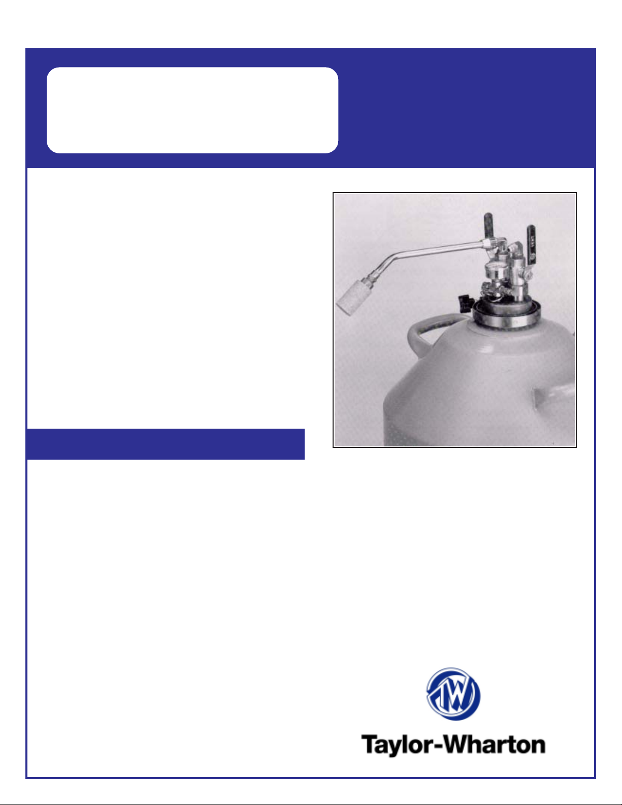
TW-43
LIQUID
WITHDRAWAL DEVICE
The Liquid Withdrawal Device (L WD) provides convenient
pressure transfer to liquid nitrogen from LD25,LD35, and
50LD Dewars. The device clamps directly to the special
neck flange that is found under the plastic trim collar
around the neck of these containers.
Flow rates up to 8 liters per minutes are possible at
operating pressures up to 10 psig (0.7 bar/69 kPa). Liquid
can be dispensed directly from the L WD via the spout
provided, or through a standard cryogenic hose connected
to the liquid outlet.
Filling a Dewar is accomplished by pressure transfer
through the withdrawal device. (See Filling Instructions.) This filling method allows replenishment of the
liquid supply in the Dewar without removing the L WD,
while keeping the liquid saturated at a pressure sufficient
to sustain liquid withdrawal.
For Liquid Nitrogen
LD25, LD35, and
50LD Dewars
Safety
Before using this equipment, read these instructions
carefully. Also, read and understand the instructions sup-
plied with your Dewar and the Handle with Care booklet
packed with all Liquid Nitrogen Dewars. The Handle with
Care booklet (Form TW-10) gives detailed information on
the safe handling of liquid nitrogen. Additional copies of
these publications can be obtained from your supplier. Do
not modify LWD or Dewar or use in a manner other than that
described in accompanying instructions and documentation.
Contact with liquid nitrogen or cold gas may cause
serious freezing (frostbite) injury . Do not touch liquid or
cold metal surfaces with your bare skin. Always wear a face
shield and gloves when transferring liquid nitrogen.
Nitrogen gas can cause suffocation without warning.
In a confined area, nitrogen gas from this equipment may
displace air required for breathing. Store and use this
equipment only in well-ventilated areas.
Use only containers designed for low-temperature
liquids. Cryogenic containers should be filled SLOWLY to
minimize stresses which can damage the container .
Vent all pressure from a Dewar before attempting to
remove the Liquid Withdrawal Device. If the band clamp
securing the L WD to a dewar is loosened while there is
pressure in the Dewar, cold gas or liquid could be expelled
causing personal injury .
Liquid Withdrawal Device is for use with liquid nitrogen
only . LWD is for use on specific model Taylor-Wharton
Dewars listed above.
Pressure in Dewar with LWD installed should never
exceed 10 psi. Fill dewar from supply source at 22 psi or
less. Do not pressurize using compressed air.
Page 2
Installation
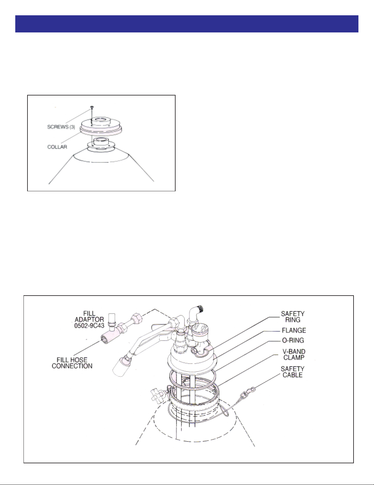
1. Remove the necktube cap/core from the Dewar.
2. Remove 3 flat-head mounting screws in the base of
the plastic trim collar around the neck of the Dewar,
remove the collar and discard or save for later. It is not
used while the LWD is installed.
3. The liquid withdrawal tube (the longer of the two plastic
tubes) is scored approximately 6 in. (152 mm) from the
end. This tube must be shortened for use with a LD25
or LD35 Dewar by breaking off the 6 in. (152 mm)
section. Discard the 6 in. (152 mm) piece. The tube is
used as supplied with the LD50.
valve. Tighten the compression nut s with a wrench to
secure.
5. Position the safety cable assembly around the top of the
Dewar, underneath the flange. Loosen V-Band Clamp
until the clamp is large enough to remove from the
L WD. Drop the band clamp around the flange on the
Dewar (see Figure 2).
6. Clean the flange O-ring and apply a thin layer of silicone
grease before placing it on the grooved flange.
NOTE: Be sure flanges surfaces are warm, clean and
dry . The O-ring must be cleaned and lightly lubricated
before installing the LWD.
7. Carefully lower the LWD unit into the Dewar. The LWD
should rest firmly centered on the neck flange of the
Dewar; the liquid withdrawal tube should not touch the
bottom of the Dewar.
8. Place the band clamp around the flanges of both the
L WD unit and the Dewar. Be sure that the clamp is
properly engaged on both flanges. Tighten the clamp –
hand tighten only .
9. Attach the snap of the safety cable to the ring on the
LWD (see figure 2).
4. Insert the longer plastic tube into the underside of the
flange assembly , beneath the LIQUID valve. Insert the
shorter plastic tube into the threaded fitting on the
underside of the flange assembly , beneath the VENT
10. If the spout assembly is to be used, install it on the
outlet fitting above the LIQUID valve. The phase separator will ensure a controlled flow of liquid.
Page 3

Installation (cont.)
11. To remove the L WD, first open the VENT valve to
release all pressure in the Dewar. Then loosen the band
clamp enough to allow it to pass over the Dewar flange,
disengage the cable snap from the ring on the L WD and
lift the withdrawal unit out of the Dewar .
Operation
Filling – It is not necessary to remove the L WD unit from
the Dewar for filling. You may fill the Dewar by pressuretransfer of liquid nitrogen through the LIQUID valve of the
LWD.
WARNING: Over pressurization of the Dewar could
result in serious bodily injury or property damage.
Never exceed the 10 psig (0.7 bar/69kPa) relief valve
pressure setting of the LWD.
To fill, remove the spout assembly and connect a 22 psig
(1.52 bar/152kPa) or lower pressure liquid supply cylinder
to the withdrawal device using a liquid nitrogen transfer
hose and the fill adapter with the L WD.
WARNING: The transfer hose must be used with a
pressure relief valve to prevent excessive pressure
buildup in the hose when the valves are closed at both
ends of the hose. If liquid nitrogen is trapped between
the valves of the liquid cylinder and the LWD, it has no
escape path as it warms and expands. The resulting
pressure can cause the hose to rupture and may cause
personal injury . The current model LWD is equipped
with a pressure relief valve. Previous versions of the
LWD must be used with a transfer hose equipped with
a pressure relief valve.
secondary relief valve, set at 15 psig (1.0 bar/103 kPa),
prevents hazardous pressure rise in the event of primary
relief valve malfunction or if its capacity is exceeded. Never
replace either of these parts with higher value relief valves;
increasing the pressure in the Dewar beyond 15 psig (1.0
bar/103 kPa) may burst the Dewar and cause personal
injury/property damage.
To fill the Dewar by pouring liquid from another container,
(This is not the recommended filling method) first open
the VENT valve to release pressure. Then, loosen the band
clamp, unsnap the safety cable, and remove the L WD unit.
When replacing the L WD on the filled Dewar, leave the
VENT valve open until the flanges are securely clamped. To
pressurize the Dewar for liquid withdrawal, refer to “Pressure Building” below.
Note: Be sure flanges surfaces are warm, clean and dry .
The o-ring must be cleaned and lightly lubricated before
replacing the L WD.
Liquid Withdrawal – When the liquid valve is opened,
pressure in the Dewar forces liquid to go up through the
withdrawal tube and out through the valve. The liquid
nitrogen can be dispensed through the spot or through
plumbing connected to the liquid outlet.
Once the transfer hose is connected, open the L WD VENT
valve first and then open the L WD LIQUID valve. Then
slowly open the liquid valve on the supply cylinder until
liquid flow is established. Adjust the VENT valve to maint ain
a back pressure of 8 to 10 psig (0.6 bar/55 kPa to 0.7 bar/
69 kPa) in the Dewar. When liquid sputters from the VENT
valve, quickly close the liquid vavle on the supply cylinder,
next the LWD LIQUID valve and then the LWD VENT valve.
WARNING: Closely monitor Dewar pressure
througout the fill process. Never let the pressure
exceed 10 psig (0.7 bar/69 kPa). If the pressure approaches 10 psig, immediately fully open the LWD
VENT valve and/or close the LWD LIQUID valve as
necessary to control the pressure in the Dewar.
Loosen the hose connection slowly and allow all pressure
and any remaining liquid to be verified before completely
disconnecting the hose.
The primary relief valve, set at 10 psig (0.7 bar/69 kPa),
maintains the normal operating pressure of the LWD. A
Pressure Building – If the Dewar is filled properly , liquid
nitrogen evaporation will normally maintain a pressure
sufficient to sustain liquid withdrawal. However , if pressure is
lost, bubbling dry nitrogen gas through the liquid may restore
proper operating pressure. This adds heat to the liquid,
causes evaporation, and increases pressure. Connect a
pressure-regulated – 8 to 10 psig (0.6 bar/55 kPa to 0.7 bar/
69 kPa) – source of dry nitrogen gas to the LIQUID connection. Open the LIQUID valve and adjust the VENT valve to
maintain a back pressure of 8 to 10 psig (0.6 bar/55 kPa to
0.7 bar/69 kPa) while the gas bubbles up through the liquid.
After several minutes, close the valves and read the pressure gauge. If the pressure does not remain above the 5
psig (0.3 bar/34 kPa), resume the gas flow until the liquid
has warmed enough to provide normal operating pressure.
External pressurization can be applied while withdrawing
liquid from the Dewar by connecting a supply of nitrogen
gas, regulated to a pressure of 8 to 10 psig (0.6 ba/55 kPa
to 0.7 bar/69 kPa), to the vent valve connection.
Page 4

Replacement Parts
Item Desc ript ion Part No.
1 Elb ow, Liquid 6814-9222
2 Elb ow, V ent 6814-9225
3 Va lve (Liquid/ V ent ) 6986-9004
4 Valve Handle Cover, Liquid D050-8C18
5 Valve Handle Cover, Vent D050-8C19
6 O-Ring for valve 8830-6142
7 Press ure Gauge
0-30 psig (0-2 bar/207 k P a) 7702-6091
8 Relief Valve
10 psi g (0.7 bar/69 k P a) 6913-9044
9 Cross, 1/8" NP T 6817-5056
10 Relief Valve
15 psig (1.0 bar/103 kP a) 6913-9046
11 O -Ring for flange 8830-6135
12 V -B and Cl am p 7342-1119
13 Warning Label D050-8C21
14 Ring for Safety Cable 8830-6311
15 S afety Cabl e A s s em bly D050-8C20
16 S pout A ssem bly D050-8C14
17 P h as e S eperat or 1193-8C80
(part of Spout A s s e m bly )
18 Tube, Liqu id Withdrawal D050-8C22
19 Tube, V ent D050-8C23
20 Loc k nut , Com pres s ion D050-8C25
21 A d aptor, Fill D050-9C43
22 Relief Valve
22 psig (2.4 bar/241 kP a) 6913-9069
23 Hex Bushing, 1/ 2" X 1/4", B ras s 6810-8998
24 S treet Tee, 1/2" NPT 6816-9210
25 V -B and Cl am p Tightening K nob 7342-1125
26 V a lve Replacement Handle 7801-5051
Ordering Information – Order all replacement parts and
accessories from your distributor. Please include the part
and model number of your refrigerator, quantity, and
description of each part requested. For more information
or the name of your local distributor, cont act Taylor-
Wharton at the address listed.
Taylor-Wharton
4075 Hamilton Boulevard
Theodore, AL 36582
Phone (334) 443-8680
Fax: (334) 443-2250
In U.S. and Canada: (800) TW TANKS (898-2657)
 Loading...