

Page 1
®
Page 2

Page 3

TABLE OF CONTENTS
KRYOS
TABLE OF CONTENTS
SAFETY PRECAUTIONS FOR LIQUID NITROGEN ........................................... 3
Extreme Cold - Cover Eyes and Exposed Skin ........................................................3
Keep Equipment Area Well Ventilated ...................................................................3
Liquid Nitrogen System .......................................................................................... 3
Electrical .................................................................................................................3
GENERAL INFORMATION ............................................................................ 4
Text Format Notation .............................................................................................4
KRYOS Specifications ..............................................................................................5
DELIVERY AND RETURNS.............................................................................. 6
Unpacking and Inspection ......................................................................................6
Freight Damage Procedures ..................................................................................6
Repackaging for Shipment ..................................................................................... 6
INSTALLATION ............................................................................................. 7
Getting Unit into Service ........................................................................................ 7
Electrical ................................................................................................................7
Power Supply Connection ..................................................................................... 7
OPERATION ................................................................................................. 7
Initial Fill ................................................................................................................7
Control Components ..............................................................................................7
Operating Parameters .........................................................................................10
Liquid Phase Storage ............................................................................................10
Thermocouple Positioning .................................................................................... 11
CONTROLLER OPERATION ......................................................................... 12
Introduction .........................................................................................................12
Normal Fill Cycle .................................................................................................12
Power ................................................................................................................... 12
Main Display Screen ............................................................................................12
The Menu System .................................................................................................13
Temperature Thermocouple Select ....................................................................... 15
Calibrate Temperature ......................................................................................... 15
Test Temperature System ....................................................................................... 15
Level Sensing .......................................................................................................15
Test Level Sensors .................................................................................................16
Alarms and Error Conditions ...............................................................................16
System Alarms ......................................................................................................16
Test Alarms ..........................................................................................................17
Logging ................................................................................................................17
Dump Logs ............................................................................................................ 18
Error Logs .............................................................................................................18
System Logs ..........................................................................................................19
Temperature Logs ................................................................................................19
Erase Logs ............................................................................................................. 19
Security ................................................................................................................19
User Options ........................................................................................................19
Lid Switch Setup ....................................................................................................20
Manual Defog .......................................................................................................20
Auto Defog ........................................................................................................... 20
Quick-Chill ............................................................................................................ 20
Control By Temperature ........................................................................................20
Temperature Control Settings ............................................................................... 20
Control Temperature ............................................................................................20
KRYOS
Page 4

KRYOS
TABLE OF CONTENTS (continued...)
Menu Password ...................................................................................................20
Serial Communications and RS-232 Settings......................................................... 21
Time and Date Set ................................................................................................. 21
User Access Logs ...................................................................................................21
Control Range .......................................................................................................21
Freeze-Guard Options ......................................................................................... 21
Valve Monitoring .................................................................................................22
Valve Open Duration ............................................................................................22
Valve De-Icing ......................................................................................................22
Splash-Guard .......................................................................................................22
Display Brightness ................................................................................................22
About this Control ................................................................................................22
Control On Battery Back-up Version .................................................................... 22
Differences Between the Regular KRYOS and the Battery Backed KRYOS.............23
Operation ............................................................................................................23
Battery Life ...........................................................................................................24
INTERFACE SOFTWARE ............................................................................. 24
Making Adjustments to the KRYOS Sensor Assembly ........................................... 24
Version 9.22 Level Reading ...................................................................................25
Recommendations for Liquid Storage ..................................................................25
Removing/Installing the Solenoid Valve ...............................................................27
Controller Electrical Tests ...................................................................................... 27
Sensor Plug Schematic ..........................................................................................28
Plumbing Assembly ...............................................................................................29
TROUBLESHOOTING .................................................................................. 30
Symptoms ............................................................................................................. 30
Controller Will Not Turn ON ................................................................................30
Indicates High Liquid Level .................................................................................. 31
Indicates Low LN
Indicates Open Sensor .......................................................................................... 32
Temperature Reading 10 to 20 Degrees Warm .....................................................32
Fill Solenoid Cycles On and Off ............................................................................ 33
Fill Solenoid Makes Humming Noise.....................................................................33
Transformer Makes Humming Noise .....................................................................33
Display = “Check” ...............................................................................................33
Lid Open Alarm ....................................................................................................33
QCF (Quick Chill Feature) Will Not Operate .......................................................33
Defog Feature Will Not Operate .......................................................................... 34
Push Buttons Will Not Respond ............................................................................ 34
Liquid Level Readout is Incorrect .........................................................................34
Power Failure Alarm ............................................................................................ 34
REPLACEMENT KRYOS CONTROLLER FIELD INSTALLATION ........................ 35
For all LABS and 38K Cryostorage Units ............................................................... 35
For 10K and 24K Cryostorage Units .....................................................................35
Factory Settings ...................................................................................................36
REPLACEMENT PARTS ................................................................................ 36
TABLE OF CONTENTS (continued...)
Menu Password ...................................................................................................20
Serial Communications and RS-232 Settings......................................................... 21
Time and Date Set ................................................................................................. 21
User Access Logs ...................................................................................................21
Control Range .......................................................................................................21
Freeze-Guard Options ......................................................................................... 21
Valve Monitoring .................................................................................................22
Valve Open Duration ............................................................................................22
Valve De-Icing ......................................................................................................22
Splash-Guard .......................................................................................................22
Display Brightness ................................................................................................22
About this Control ................................................................................................22
Control On Battery Back-up Version .................................................................... 22
Differences Between the Regular KRYOS and the Battery Backed KRYOS.............23
Operation ............................................................................................................23
Battery Life ...........................................................................................................24
INTERFACE SOFTWARE ............................................................................. 24
Making Adjustments to the KRYOS Sensor Assembly ........................................... 24
Version 9.22 Level Reading ...................................................................................25
Recommendations for Liquid Storage ..................................................................25
Removing/Installing the Solenoid Valve ...............................................................27
Controller Electrical Tests ...................................................................................... 27
Sensor Plug Schematic ..........................................................................................28
Plumbing Assembly ...............................................................................................29
TROUBLESHOOTING .................................................................................. 30
Symptoms ............................................................................................................. 30
Controller Will Not Turn ON ................................................................................30
Indicates High Liquid Level .................................................................................. 31
Indicates Low LN2 Supply ...................................................................................... 32
Indicates Open Sensor .......................................................................................... 32
Temperature Reading 10 to 20 Degrees Warm .....................................................32
Fill Solenoid Cycles On and Off ............................................................................ 33
Fill Solenoid Makes Humming Noise.....................................................................33
Transformer Makes Humming Noise .....................................................................33
Display = “Check” ...............................................................................................33
Lid Open Alarm ....................................................................................................33
QCF (Quick Chill Feature) Will Not Operate .......................................................33
Defog Feature Will Not Operate .......................................................................... 34
Push Buttons Will Not Respond ............................................................................ 34
Liquid Level Readout is Incorrect .........................................................................34
Power Failure Alarm ............................................................................................ 34
REPLACEMENT KRYOS CONTROLLER FIELD INSTALLATION ........................ 35
For all LABS and 38K Cryostorage Units ............................................................... 35
For 10K and 24K Cryostorage Units .....................................................................35
Factory Settings ...................................................................................................36
REPLACEMENT PARTS ................................................................................ 36
Supply ...................................................................................... 32
2
SERVICE AND MAINTENANCE HISTORY LOG ............................................. 37
SERVICE AND MAINTENANCE HISTORY LOG ............................................. 37
Page 5

KRYOS
SAFETY PRECAUTIONS FOR LIQUID
NITROGEN
Nitrogen is an inert, colorless, odorless, and tasteless gas making up four-fifths of
the air you breathe – and can be very dangerous. Air is roughly one-fifth oxygen.
Liquid nitrogen is at a temperature of -196°C (-320°F) under normal atmospheric
pressure.
Extreme Cold - Cover Eyes and Exposed Skin
Accidental contact of liquid nitrogen or cold issuing gas with the skin or eyes may
cause a freezing injury similar to frostbite. Handle the liquid so that it won’t splash
or spill. Protect your eyes and cover the skin where the possibility of contact with the
liquid, cold pipes and cold equipment, or cold gas exists. Safety goggles or a face
shield should be worn when operating this equipment. Insulated gloves that can be
easily removed and long sleeves are recommended for arm protection. Trousers
without cuffs should be worn outside boots or over the shoes to shed spilled liquid.
Keep Equipment Area Well Ventilated
Although nitrogen is non-toxic and non-flammable, it can cause asphyxiation in
a confined area without adequate ventilation. Any atmosphere not containing
enough oxygen for breathing can cause dizziness, unconsciousness, or even death.
Nitrogen, a colorless, odorless, and tasteless gas, that cannot be detected by the
human senses and will be inhaled normally as if it were air. Without adequate
ventilation, the expanding nitrogen will displace the normal air resulting in death.
Liquid Nitrogen System
The liquid nitrogen supply pressure at the inlet to the refrigerator should be in
the range of 10 psig (0.7 bar/69 kPa) to 20 psig (1.4 bar/138 kPa) for optimum
performance. Higher operating pressures will increase transfer losses and create
excessive turbulence of the liquid in the refrigerator which can generate false signals
to the liquid level controller causing the refrigerator to under-fill. In “liquid phase”
storage applications, excessive turbulence can cause splashing which could result in
personal injury and/or damage to the refrigerator. When installing piping or fill hose
assemblies, make certain a suitable safety relief valve is installed in each section of
plumbing between shut-off and solenoid valves. Trapped liquefied gas will expand
greatly as it warms and may burst hoses or piping causing damage or personal
injury. A relief valve is installed in the refrigerator plumbing to protect the line
between the customer supplied shut-off valve and the refrigerator solenoid valve.
WARNING:
The following safety
precautions are for
your protection.
Before installing,
operating, or
maintaining this unit
read and follow all
safety precautions
in this section
and in reference
publications. Failure
to observe all safety
precautions can
result in property
damage, personal
injury, or possibly
death.
Caution:
When installing field
fabricated piping,
make certain a
suitable safety relief
valve is installed
in each section of
piping between
shut-off and solenoid
valves.
WARNING:
Inlet pressure should
not exceed 22 psig
(1.5 bar/152 kPa).
Higher pressures
could result
in damage to
equipment.
Electrical
The liquid level controllers used with these refrigerators operate from 24/16.5 VAC.
However, the external transformer does have a 110/220 VAC primary. Disconnect
the electrical power cord from the outlet before attempting any service.
For more detailed information concerning safety precautions and safe practices
to be observed when handling cryogenic liquids consult CGA pamphlet P-12
“Handling Cryogenic Liquids” available from the Compressed Gas Association,
1235 Jefferson Davis Highway, Arlington, VA 22202.
WARNING:
Electrical shock can
kill. Do not attempt
any service on these
units without first
disconnecting the
electrical power cord.
3
Page 6

KRYOS
KRYOS
GENERAL INFORMATION
The KRYOS Controller can monitor and control both the liquid nitrogen level and
the vapor temperature range in the cryostorage unit you have selected. KRYOS
controllers are designed to work with Taylor-Wharton LABS and K-Series Cryostorage
Systems. The features are designed to provide a safe environment for samples while
at the same time tracking all relevant information associated with the freezer. This
control provides a complete historical record of the environment in your unit and
therefore, the environment in which your samples have been stored in this system.
This controller features a vacuum fluorescent display. The addition of a liquid
nitrogen supply and inventory control racks for systematic retrieval of stored product
completes the total Cryostorage System.
Taylor-Wharton LABS and K-Series Cryostorage Systems are designed for
applications where extremely low temperature storage of biological products is
required. They are also appropriate for industrial or other applications where liquid
nitrogen temperatures and high capacity are needed.
Text Format Notation
In this owner’s manual, we use some special text formats to denote certain portions
of the system. These are listed below:
t Menu is indicated in ALL CAPS BOLD.
t Actual Menu Choices are indicated in ALL CAPS.
t Start Fill and Stop Fill sensors are indicated in ALL CAPS ITALICS.
t Specific Menu Descriptions under a main category are listed in Italics.
Before beginning installation or operation of this KRYOS Controller, make sure
that you read and understand this manual as well as the operating and safety
instructions for the cryostorage unit you will be using with this controller.
5
KRYOS
KRYOS Specifications
Configurations: Designed exclusively for all Taylor-Wharton LABS and K-Series
Cryostorage Systems
Power Supply: 24VAC – No Battery
16.5 VAC – Battery Back-up Version
Sensor Assembly: Freeze-Guard Assembly – Standard
8-Thermistor Assembly – Optional
4-Thermistor Assembly – Optional
Thermocouples: Operates with none, 1 or 2 Type T Thermocouples
(1 Thermocouple standard)
Solenoid Valve: 24VAC – No Battery
12VDC – Battery Back-up Version
Control Type: Temperature & Liquid Nitrogen Level Control
Security: User Access via 4-digit Password
Power On/Off Password
Menu access Password
Alarms: Audible
Visual red
Remote alarm relay
LED Alarm description
Diagnostics: Circuit diagnostics at start-up
Sensor diagnostics
Lid Switch
Thermocouple diagnostics
Manual Test for audible, visual and remote alarms
Temp. Calibration: Automated calibration from the front panel
Communications: RS-232 Serial Port for 2-way communications capable
Logging Capacity: System Logs (4096 events)
Alarm Logs (4096 events)
Temperature Logs (32,768 events)
KRYOS
GENERAL INFORMATION
The KRYOS Controller can monitor and control both the liquid nitrogen level and
the vapor temperature range in the cryostorage unit you have selected. KRYOS
controllers are designed to work with Taylor-Wharton LABS and K-Series Cryostorage
Systems. The features are designed to provide a safe environment for samples while
at the same time tracking all relevant information associated with the freezer. This
control provides a complete historical record of the environment in your unit and
therefore, the environment in which your samples have been stored in this system.
This controller features a vacuum fluorescent display. The addition of a liquid
nitrogen supply and inventory control racks for systematic retrieval of stored product
completes the total Cryostorage System.
Taylor-Wharton LABS and K-Series Cryostorage Systems are designed for
applications where extremely low temperature storage of biological products is
required. They are also appropriate for industrial or other applications where liquid
nitrogen temperatures and high capacity are needed.
Text Format Notation
In this owner’s manual, we use some special text formats to denote certain portions
of the system. These are listed below:
t Menu is indicated in ALL CAPS BOLD.
t Actual Menu Choices are indicated in ALL CAPS.
t Start Fill and Stop Fill sensors are indicated in ALL CAPS ITALICS.
t Specific Menu Descriptions under a main category are listed in Italics.
Before beginning installation or operation of this KRYOS Controller, make sure
that you read and understand this manual as well as the operating and safety
instructions for the cryostorage unit you will be using with this controller.
®
4
Page 7

KRYOS
KRYOS
KRYOS Specifications
Configurations: Designed exclusively for all Taylor-Wharton LABS and K-Series
Cryostorage Systems
Power Supply: 24VAC – No Battery
16.5 VAC – Battery Back-up Version
Sensor Assembly: Freeze-Guard Assembly – Standard
8-Thermistor Assembly – Optional
4-Thermistor Assembly – Optional
Thermocouples: Operates with none, 1 or 2 Type T Thermocouples
(1 Thermocouple standard)
Solenoid Valve: 24VAC – No Battery
12VDC – Battery Back-up Version
Control Type: Temperature & Liquid Nitrogen Level Control
Security: User Access via 4-digit Password
Power On/Off Password
Menu access Password
Alarms: Audible
Visual red
Remote alarm relay
LED Alarm description
Diagnostics: Circuit diagnostics at start-up
Sensor diagnostics
Lid Switch
Thermocouple diagnostics
Manual Test for audible, visual and remote alarms
Temp. Calibration: Automated calibration from the front panel
Communications: RS-232 Serial Port for 2-way communications capable
Logging Capacity: System Logs (4096 events)
Alarm Logs (4096 events)
Temperature Logs (32,768 events)
KRYOS
KRYOS Specifications
Configurations: Designed exclusively for all Taylor-Wharton LABS and K-Series
Power Supply: 24VAC – No Battery
Sensor Assembly: Freeze-Guard Assembly – Standard
Thermocouples: Operates with none, 1 or 2 Type T Thermocouples
Solenoid Valve: 24VAC – No Battery
Control Type: Temperature & Liquid Nitrogen Level Control
Security: User Access via 4-digit Password
Alarms: Audible
Cryostorage Systems
16.5 VAC – Battery Back-up Version
8-Thermistor Assembly – Optional
4-Thermistor Assembly – Optional
(1 Thermocouple standard)
12VDC – Battery Back-up Version
Power On/Off Password
Menu access Password
Visual red
Remote alarm relay
LED Alarm description
Diagnostics: Circuit diagnostics at start-up
Temp. Calibration: Automated calibration from the front panel
Communications: RS-232 Serial Port for 2-way communications capable
Logging Capacity: System Logs (4096 events)
Sensor diagnostics
Lid Switch
Thermocouple diagnostics
Manual Test for audible, visual and remote alarms
Alarm Logs (4096 events)
Temperature Logs (32,768 events)
5
Page 8
KRYOS
KRYOS
DELIVERY AND RETURNS
Unpacking and Inspection
Inspect shipping containers for external damage.
All claims for damage (apparent or concealed)
or partial loss of shipment must be made in
writing within five (5) days from receipt of goods.
If damage or loss is apparent, please notify the
appropriate parties as indicated below:
Domestic LTL Shipments – The customer
should notify and file the appropriate damage
claims with the carrier. All products are shipped
FOB Origin.
Domestic UPS Shipments – Any damage
should be noted and reported to shipper upon
delivery, and Taylor-Wharton must also be notified. Confirm with Taylor-Wharton
Customer Service the filing procedures for any UPS damage claims.
International Shipments – Any damage and/or claims are to be filed with the
carrier. Insurance agent(s) and customs’ brokers should also be notified.
In all cases, Taylor-Wharton should be notified so we can assist if needed
in filing damage claims.
Open the shipping containers; a packing list is included with the system to simplify
checking that all components, cables, accessories, and manuals were received.
Please use the packing list to check off each item as the system is unpacked. Inspect
for damage. Be sure to inventory all components supplied before discarding any
shipping materials. If there is damage to the system during transit, be sure to file
proper claims promptly. Please advise Taylor-Wharton of such filings. In case of parts
or accessory shortages, advise Taylor-Wharton immediately. Taylor-Wharton cannot
be responsible for any missing parts unless notified within 60 days of shipment.
Freight Damage Procedures
Any freight damage claims are your responsibility. Cryostorage Systems
are delivered to your carrier from Taylor-Wharton’s dock in new
condition; when you receive our product you may expect it to be in that
same condition. For your own protection, take time to visually inspect each
shipment in the presence of the carrier’s agent before you accept delivery. If any
damage is observed, make an appropriate notation on the freight bill. Then, ask the
driver to sign the notation before you receive the equipment. You should decline to
accept containers that show damage which might affect serviceability.
Repackaging for Shipment
If it is necessary to return any part of the system for repair or replacement, a
Material Return Authorization (MRA) number must be obtained from an authorized
factory representative before returning the equipment to our service department.
Contact your distributor for return authorization. When returning equipment for
service, the following information must be provided before obtaining an MRA:
A. System model and serial number, and controller model and unit, if available.
B. User’s name, company, address, and phone number
C. Malfunction symptoms
Figure 1.0 Crated LABS 38K
DELIVERY AND RETURNS
Unpacking and Inspection
Inspect shipping containers for external damage.
All claims for damage (apparent or concealed)
or partial loss of shipment must be made in
writing within five (5) days from receipt of goods.
If damage or loss is apparent, please notify the
appropriate parties as indicated below:
Domestic LTL Shipments – The customer
should notify and file the appropriate damage
claims with the carrier. All products are shipped
FOB Origin.
Figure 1.0 Crated LABS 38K
delivery, and Taylor-Wharton must also be notified. Confirm with Taylor-Wharton
Customer Service the filing procedures for any UPS damage claims.
International Shipments – Any damage and/or claims are to be filed with the
carrier. Insurance agent(s) and customs’ brokers should also be notified.
Domestic UPS Shipments – Any damage
should be noted and reported to shipper upon
In all cases, Taylor-Wharton should be notified so we can assist if needed
in filing damage claims.
Open the shipping containers; a packing list is included with the system to simplify
checking that all components, cables, accessories, and manuals were received.
Please use the packing list to check off each item as the system is unpacked. Inspect
for damage. Be sure to inventory all components supplied before discarding any
shipping materials. If there is damage to the system during transit, be sure to file
proper claims promptly. Please advise Taylor-Wharton of such filings. In case of parts
or accessory shortages, advise Taylor-Wharton immediately. Taylor-Wharton cannot
be responsible for any missing parts unless notified within 60 days of shipment.
Freight Damage Procedures
Any freight damage claims are your responsibility. Cryostorage Systems
are delivered to your carrier from Taylor-Wharton’s dock in new
condition; when you receive our product you may expect it to be in that
same condition. For your own protection, take time to visually inspect each
shipment in the presence of the carrier’s agent before you accept delivery. If any
damage is observed, make an appropriate notation on the freight bill. Then, ask the
driver to sign the notation before you receive the equipment. You should decline to
accept containers that show damage which might affect serviceability.
Repackaging for Shipment
If it is necessary to return any part of the system for repair or replacement, a
Material Return Authorization (MRA) number must be obtained from an authorized
factory representative before returning the equipment to our service department.
Contact your distributor for return authorization. When returning equipment for
service, the following information must be provided before obtaining an MRA:
A. System model and serial number, and controller model and unit, if available.
B. User’s name, company, address, and phone number
C. Malfunction symptoms
6
Page 9

If possible, the original packing material should be retained for reshipment. If not
available, consult Taylor-Wharton for shipping and packing instructions. It is the
responsibility of the customer to assure that the goods are adequately packaged for
return to the factory. All refrigerators returned to Taylor-Wharton must be clean and
sterile before return. See page 13 for cleaning instructions.
KRYOS
INSTALLATION
Getting Unit into Service
Your Cryostorage System should come with complete instructions for how you should
remove the unit from the crate and put it into service. Read both this manual and
your Cryostorage System’s manual before beginning any installation. Make sure to
follow any required procedures and safety guidelines when you are hooking up your
Liquid Nitrogen source.
Electrical
The liquid level controllers used with these refrigerators operate from 24/16.5 VAC.
However, the external transformer does have a 110/220 VAC primary. Disconnect
the electrical power cord from the outlet before attempting any service.
Power Supply Connection
Connect the power supply to your LABS or K-Series Cryostorage System and then
plug the power supply into a surge protected 110/220 VAC outlet.
OPERATION
These instructions are for operators experienced with cryogenic equipment. Before
operating the system, become familiar with the safety precautions in this manual
and in reference publications. Make certain all applicable provisions set forth in the
Installation Section have been followed before placing a system in operation. Study
this manual thoroughly. Know the location and function of all system components.
Initial Fill
NOTE:
For KRYOS Field
Installation instructions
refer to Page 35.
CAUTION:
If using a power
source other than
North American
110/220 VAC,
contact TaylorWharton Customer
Service to make
sure you are using
the appropriate
converter. Use of an
unapproved power
source converter may
cause permanent
damage to the unit.
WARNING:
Electrical shock can
kill. Do not attempt
any service on these
units without first
disconnecting the
electrical power cord.
The Cryostorage System using the KRYOS controller, comes preset from the factory.
The liquid nitrogen supply pressure at the inlet to the refrigerator should be in
the range of 10 psig (0.7 bar/69 kPa) to 20 psig (1.4 bar/138 kPa) for optimum
performance. Higher operating pressures will increase transfer losses and create
excessive turbulence of the liquid in the refrigerator which can generate false signals
to the liquid level controller causing the refrigerator to under fill. In “liquid phase”
storage applications, excessive turbulence can cause splashing which could result in
personal injury.
Control Components
Interface Panel
The KRYOS Interface panel, which the user will interact with, contains the vacuum
fluorescent display as well as the number keypad, power button, help button and the
soft-key control buttons. (See Figure 2.0 and 2.1 on following page.)
WARNING:
Maintain adequate
ventilation to
prevent asphyxiation
hazard (see Safety
Precautions).
WARNING:
If the fill fails to
stop for any reason,
quickly close the
liquid supply valve
to prevent overfilling
until the cause of
the problem can be
determined.
7
Page 10
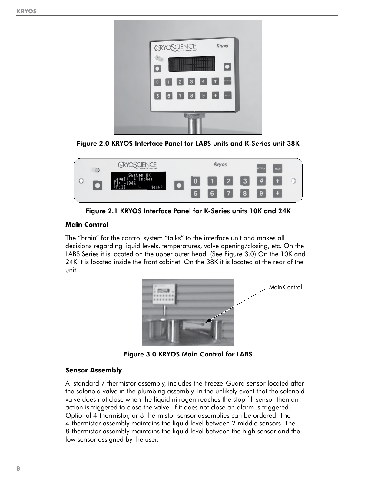
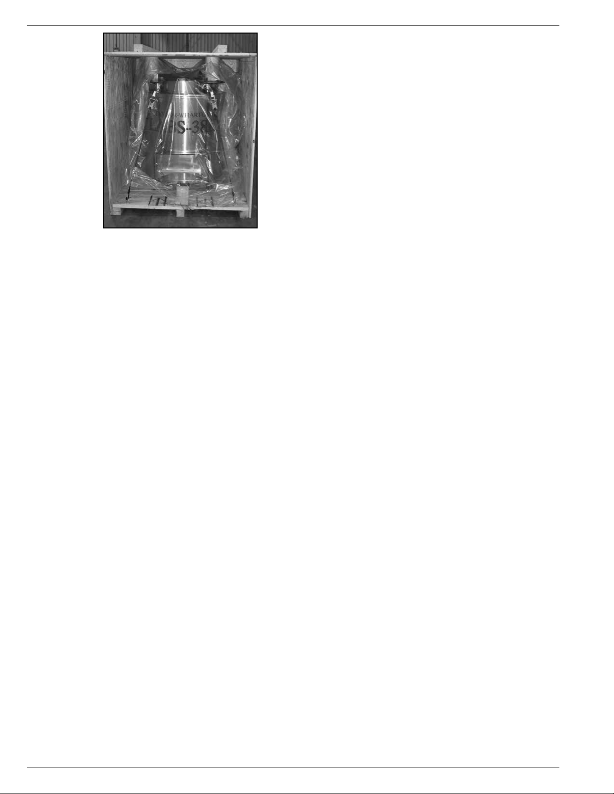
Figure 2.0 KRYOS Interface Panel for LABS units and K-Series unit 38K
Figure 2.1 KRYOS Interface Panel for K-Series units 10K and 24K
Main Control
The “brain” for the control system “talks” to the interface unit and makes all
decisions regarding liquid levels, temperatures, valve opening/closing, etc. On the
LABS Series it is located on the upper outer head. (See Figure 3.0) On the 10K and
24K it is located inside the front cabinet. On the 38K it is located at the rear of the
unit.
Main Control
Figure 3.0 KRYOS Main Control for LABS
Sensor Assembly
A standard 7 thermistor assembly, includes the Freeze-Guard sensor located after
the solenoid valve in the plumbing assembly. In the unlikely event that the solenoid
valve does not close when the liquid nitrogen reaches the stop fill sensor then an
action is triggered to close the valve. If it does not close an alarm is triggered.
Optional 4-thermistor, or 8-thermistor sensor assemblies can be ordered. The
4-thermistor assembly maintains the liquid level between 2 middle sensors. The
8-thermistor assembly maintains the liquid level between the high sensor and the
low sensor assigned by the user.
KRYOS
8
Page 11
KRYOS
Lid Switch
KRYOS
Lid Switch
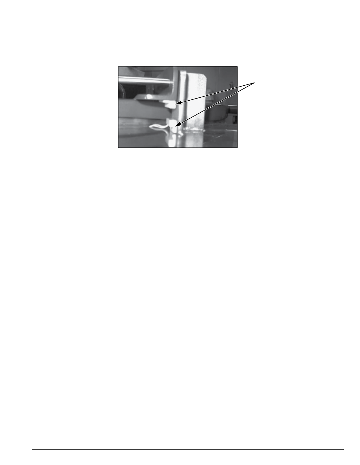
The LABS and 38K Lid Switch (Fig 4.0) is attached to the hinge while the K-Series
Lid Switch is attached to the lid and determines whether or not the lid is open on the
freezer. This also allows the control to determine whether to activate the Quick Chill,
Auto Defog or Lid Alarm features.
Lid Switch
Figure 4.0 LABS and 38K Lid Switch
Solenoid Valve
These units are designed to work with 12 VDC solenoid valve manufactured by
ASCO (see Plumbing Assembly Figures on pages 29 and 30).
Thermocouples
Type T thermocouples determine the temperature in the freezer. The user may
choose to use NONE, 1 or 2 thermocouples with this control at any time. (The unit
comes complete with one Thermocouple)
Wall Transformer
A 24 VAC wall transformer is supplied for the KRYOS version (No Battery). The
system is supplied with a transformer compatible with common household (North
American) 110VAC. (For other power outlets contact Taylor-Wharton Customer
Service.) These wall transformers have UL approval. UL approval for the system as a
whole is not required since the control operates on low voltage. If your power source
differs, or is subject to disruption or line surges due to other equipment on line,
consult your Taylor-Wharton representative.
Optional Wall Transformer with Battery Back-up
This option has a 12VDC battery installed underneath the unit’s tabletop for the
LABS units and at the rear on the K-Series units.
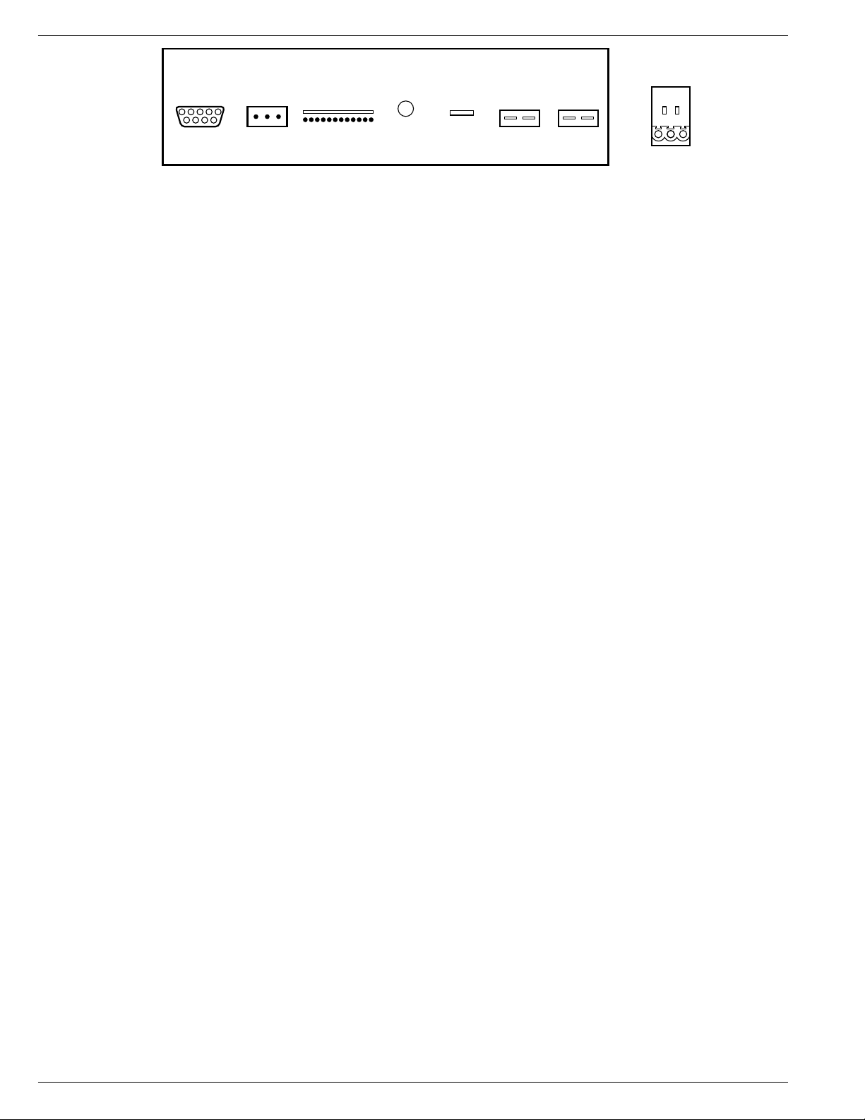
Remote Alarm
If an error condition occurs after a user defined period of time, a remote alarm
circuit can be initiated. This is accomplished by connecting a remote device to
the remote alarm jack on the rear electrical panel. The 3-pin jack on the back of
the unit provides continuity between pin #2 (common) and pin #3 in the normal
condition. Continuity between pin #1 and pin #2 is provided in an error condition.
(See Figure 5.0 below.)
KRYOS
The LABS and 38K Lid Switch (Fig 4.0) is attached to the hinge while the K-Series
Lid Switch is attached to the lid and determines whether or not the lid is open on the
freezer. This also allows the control to determine whether to activate the Quick Chill,
Auto Defog or Lid Alarm features.
Lid Switch
Figure 4.0 LABS and 38K Lid Switch
Solenoid Valve
These units are designed to work with 12 VDC solenoid valve manufactured by
ASCO (see Plumbing Assembly Figures on pages 29 and 30).
Thermocouples
Type T thermocouples determine the temperature in the freezer. The user may
choose to use NONE, 1 or 2 thermocouples with this control at any time. (The unit
comes complete with one Thermocouple)
Wall Transformer
A 24 VAC wall transformer is supplied for the KRYOS version (No Battery). The
system is supplied with a transformer compatible with common household (North
American) 110VAC. (For other power outlets contact Taylor-Wharton Customer
Service.) These wall transformers have UL approval. UL approval for the system as a
whole is not required since the control operates on low voltage. If your power source
differs, or is subject to disruption or line surges due to other equipment on line,
consult your Taylor-Wharton representative.
Optional Wall Transformer with Battery Back-up
This option has a 12VDC battery installed underneath the unit’s tabletop for the
LABS units and at the rear on the K-Series units.
Remote Alarm
If an error condition occurs after a user defined period of time, a remote alarm
circuit can be initiated. This is accomplished by connecting a remote device to
the remote alarm jack on the rear electrical panel. The 3-pin jack on the back of
the unit provides continuity between pin #2 (common) and pin #3 in the normal
condition. Continuity between pin #1 and pin #2 is provided in an error condition.
(See Figure 5.0 below.)
9
Page 12
KRYOS
KRYOS
Comm Port
(RS-232)
Remote
Alarm
Remote Alarm:
Normal Condition............. Continuity Between pins 2 and 3
Alarm Condition................. Continuity Between pins 1 and 2
Sensor 24 VAC
Power
Solenoid Temp 1
(Receptacle
View)
Temp 2
3
1 - Purple Wire: Normally Closed
2 - Orange Wire: Normally Open
3 - Grey Wire: Normally Open
21
Figure 5.0 Remote Alarm Plug Connection
Operating Parameters
When materials are immersed in liquid nitrogen, they will assume the temperature
of the liquid (-196°C/-320°F). When material is stored in the vapor phase over the
liquid, the liquid nitrogen is still a very cold refrigerant, but the refrigerator’s interior
temperature increases somewhat as product is stored higher over the liquid. This
temperature differential is not significant in many biological storage applications,
and is affected by the amount of product stored in the refrigerator, the type and size
of inventory control system, and the liquid level in the unit.
The liquid level in the refrigerator is determined by the position of the of the
Thermistor Assembly in the sensor tube. These sensors are set at installation to
maintain a specific liquid level. A filling cycle is initiated when the level falls below
the Start Fill sensor and is completed when the Stop Fill sensor is reached. This
filling cycle repeats when the level fall below the Start Fill sensor. Sensor Probe
assignments may be changed on the controller keypad to define new start and stop
levels, and these levels may be set independently to vary the liquid level differential
between fills. Prior to the initial fill of the refrigerator, a determination should be
made whether vapor phase or liquid phase storage will be utilized.
All units are supplied with a seven thermistor assembly and a freeze-guard sensor
unless otherwise specified. Factory setting positions for the K-Series are Start Fill 3 in.
(76.2 mm) and Stop position 6 in. (152.4 mm). The LABS factory setting positions
will maintain liquid level within a distance of 2 in. (50.8 mm) from the bottom of the
operating tray on the LABS 20K, 38K, 40K, 80K units, and 3 in. (76.2 mm) from the
bottom of the operating tray on the LABS 94K.
Liquid Phase Storage
Liquid phase storage is normally utilized when liquid nitrogen temperatures are
required to maintain stored product viability and the storage medium is adequate
for storage in liquid nitrogen.
In a typical liquid phase storage system, the liquid level sensors are positioned to
maintain the liquid level at or below the top level of the inventory control system.
During operation, the upper levels of the inventory control system will at times
become exposed as the liquid level fluctuates.
Care must be taken to ensure that the liquid level remains below the bottom of the
refrigerator lid. Exposure to liquid nitrogen may result in physical damage to the lid.
Additionally, operating the refrigerator with high liquid levels characteristic of liquid
phase storage may result in turbulence during fill cycles. Caution must be exercised
if the refrigerator lid is opened during a fill, and appropriate safety equipment
should always be worn.
View)
21
(Receptacle
Comm Port
(RS-232)
Operating Parameters
When materials are immersed in liquid nitrogen, they will assume the temperature
of the liquid (-196°C/-320°F). When material is stored in the vapor phase over the
liquid, the liquid nitrogen is still a very cold refrigerant, but the refrigerator’s interior
temperature increases somewhat as product is stored higher over the liquid. This
temperature differential is not significant in many biological storage applications,
and is affected by the amount of product stored in the refrigerator, the type and size
of inventory control system, and the liquid level in the unit.
The liquid level in the refrigerator is determined by the position of the of the
Thermistor Assembly in the sensor tube. These sensors are set at installation to
maintain a specific liquid level. A filling cycle is initiated when the level falls below
the Start Fill sensor and is completed when the Stop Fill sensor is reached. This
filling cycle repeats when the level fall below the Start Fill sensor. Sensor Probe
assignments may be changed on the controller keypad to define new start and stop
levels, and these levels may be set independently to vary the liquid level differential
between fills. Prior to the initial fill of the refrigerator, a determination should be
made whether vapor phase or liquid phase storage will be utilized.
Remote
Alarm
Remote Alarm:
Normal Condition............. Continuity Between pins 2 and 3
Alarm Condition................. Continuity Between pins 1 and 2
Sensor 24 VAC
Figure 5.0 Remote Alarm Plug Connection
Power
Solenoid Temp 1
Temp 2
1 - Purple Wire: Normally Closed
2 - Orange Wire: Normally Open
3 - Grey Wire: Normally Open
3
All units are supplied with a seven thermistor assembly and a freeze-guard sensor
unless otherwise specified. Factory setting positions for the K-Series are Start Fill 3 in.
(76.2 mm) and Stop position 6 in. (152.4 mm). The LABS factory setting positions
will maintain liquid level within a distance of 2 in. (50.8 mm) from the bottom of the
operating tray on the LABS 20K, 38K, 40K, 80K units, and 3 in. (76.2 mm) from the
bottom of the operating tray on the LABS 94K.
Liquid Phase Storage
Liquid phase storage is normally utilized when liquid nitrogen temperatures are
required to maintain stored product viability and the storage medium is adequate
for storage in liquid nitrogen.
In a typical liquid phase storage system, the liquid level sensors are positioned to
maintain the liquid level at or below the top level of the inventory control system.
During operation, the upper levels of the inventory control system will at times
become exposed as the liquid level fluctuates.
Care must be taken to ensure that the liquid level remains below the bottom of the
refrigerator lid. Exposure to liquid nitrogen may result in physical damage to the lid.
Additionally, operating the refrigerator with high liquid levels characteristic of liquid
phase storage may result in turbulence during fill cycles. Caution must be exercised
if the refrigerator lid is opened during a fill, and appropriate safety equipment
should always be worn.
10
Page 13

KRYOS
KRYOS
KRYOS
The Taylor-Wharton Cryostorage Systems are set at factory for vapor phase storage.
To reconfigure the system’s settings for liquid phase, the following steps should be
used.
1. Power up the unit.
2. On K-Series units, you must cut the wire ties to begin the adjustments.
3. Remove the “Start Fill”, “Stop Fill” (Thermistor) sensors from the sensor tube.
4. Allow the unit to fill to your desired “Stop Fill” elevation.
5. Stop the fill by closing the supply line valve.
6. On the interface panel, push (MENU, 2, 1).
7. Insert the “Start Fill”, “Stop Fill” (Thermistor) sensors until the #6 sensor changes
on the display from G (gas) to L (liquid).
8. Return to the main (MENU).
9. For K-Series units, the sensor tube and thermistor will need to be reattached
using wire ties.
10. Dress wires and seal with stopper to fix sensor at the new elevation.
Thermocouple Positioning
Temperature is measured by a Thermocouple. In the K-Series the Thermocouple is
also located in the Sensor Tube while in the LABS Series, it is in a separate tube. The
Thermocouple is located level with the top shelf of the inventory rack.
11
Page 14

KRYOS
KRYOS
CONTROLLER OPERATION
This section of the operating manual is for Taylor-Wharton approved equipment that
uses the KRYOS controller.
Introduction
The KRYOS temperature and LN2 level controller is designed for easy operation
and uninterrupted, reliable service. This controller will maintain the selected
liquid level range of LN
2
in your refrigerator as well as provide audible and
visual alarms for any alarm conditions that may occur. An Alarm is any condition
outside the activated preset limits on the control, such as an open sensor circuit or
temperature alarm. “System Events” are lid openings and closings, solenoid valve
openings and closing, and operation of the controller’s relay for remote alarm
indication. System Events, Alarms and Temperature “Data” can be downloaded.
The KRYOS controller should require no additional attention to maintain
liquid level if an adequate supply source of liquid nitrogen is maintained. If
your protocol calls for you to “top-off” the Cryostorage System at the end of
a workday or workweek, press the FILL button. The unit will fill to the upper
allowable liquid level and stop automatically. You may choose to manually stop
the fill by pressing the STOP button at anytime during the fill.
Normal Fill Cycle
When the refrigerator is filled and the controller is operating, the START FILL and
LOW ALARM sensors are immersed in liquid nitrogen. Their resistance values
are interpreted by the controller as “in liquid”. At the same time, the STOP FILL
and the HIGH ALARM sensors are above the liquid pool, informing the control
that these sensors are in vapor. As liquid nitrogen evaporates, the liquid level
in the refrigerator drops slowly until the START FILL sensor is above the liquid
and sends a different signal to the controller. After a delay sufficient to ensure
the signal, the controller interprets this condition as low liquid and opens the fill
solenoid, admitting more liquid nitrogen from the supply source.
The refrigerator will fill slowly. The fill continues until the STOP FILL sensor sends
the controller a signal that it is now in liquid. The controller will close the liquid
supply solenoid to stop the fill. As liquid evaporates, the display will indicate the
liquid is at a normal level as the cycle begins again.
Power
The control can be turned on and off by pressing the Power button followed by “42”,
as instructed on the display panel. The two-step shutdown is a precaution against
accidental shutdown. Shutdown can also be password protected to prevent users
from turning the system on and off under the security section of this manual.
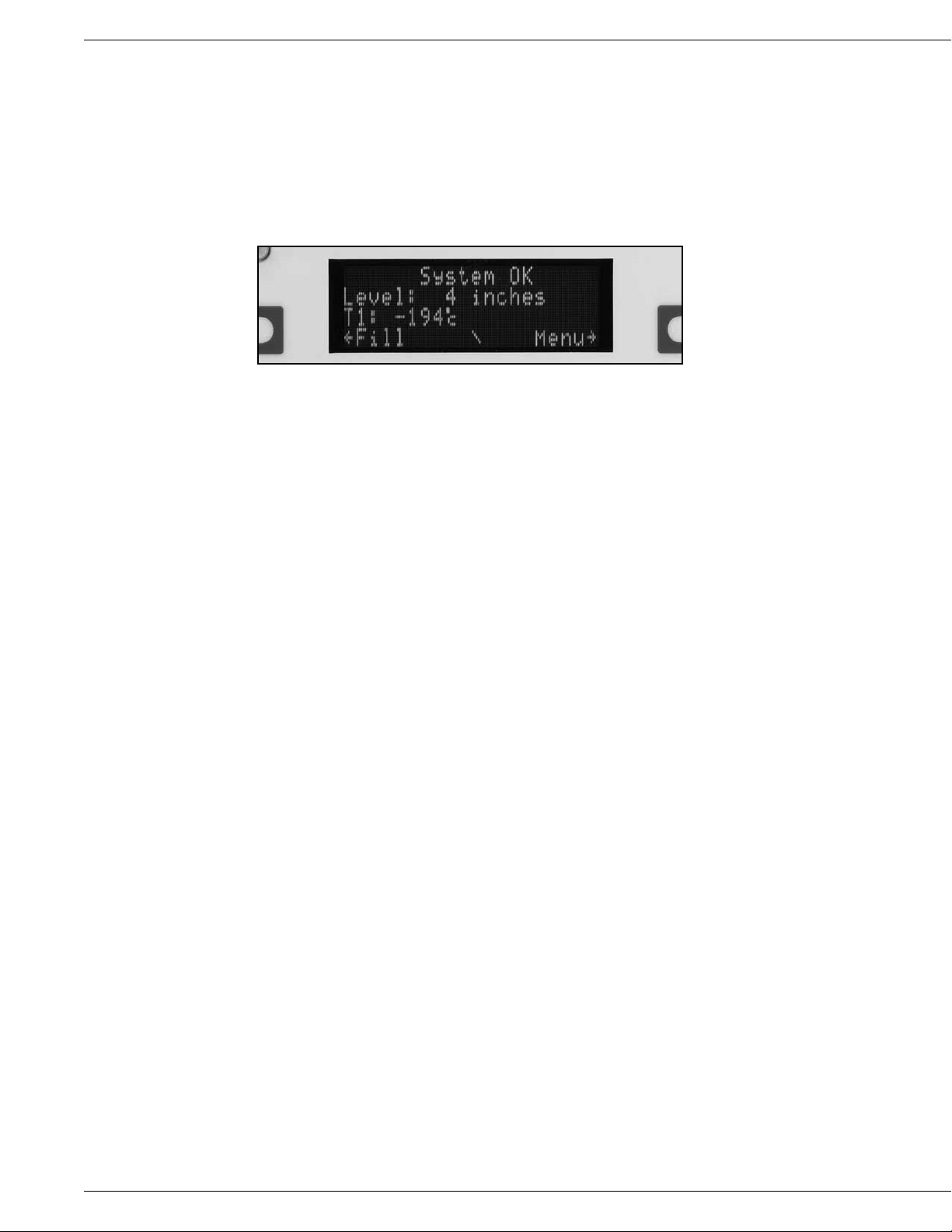
Main Display Screen
The main display screen consists of 4 lines of information.
Line 1: Displays the current status of the control. It indicates if all systems are normal
or if any errors have been detected. Error messages disappear when the
error is corrected.
Line 2: Displays the level sensing in the control. If the 7-thermistor or 8-thermistor
assembly is being used, the control will indicate actual liquid level in the
freezer. If a 4-thermistor assembly is being used, the control will indicate
LOW if the liquid level is below Start Fill sensor #2, NORMAL if the liquid
level is between sensor #2 and sensor #3, and HIGH if the liquid level is
above Stop Fill sensor #3. In addition, LOW LEVEL ALARM is indicated when
the liquid level is below sensor #1 and HIGH LEVEL ALARM is indicated
when liquid level is above sensor #4.
CONTROLLER OPERATION
This section of the operating manual is for Taylor-Wharton approved equipment that
uses the KRYOS controller.
Introduction
The KRYOS temperature and LN2 level controller is designed for easy operation
and uninterrupted, reliable service. This controller will maintain the selected
liquid level range of LN
visual alarms for any alarm conditions that may occur. An Alarm is any condition
outside the activated preset limits on the control, such as an open sensor circuit or
temperature alarm. “System Events” are lid openings and closings, solenoid valve
openings and closing, and operation of the controller’s relay for remote alarm
indication. System Events, Alarms and Temperature “Data” can be downloaded.
The KRYOS controller should require no additional attention to maintain
liquid level if an adequate supply source of liquid nitrogen is maintained. If
your protocol calls for you to “top-off” the Cryostorage System at the end of
a workday or workweek, press the FILL button. The unit will fill to the upper
allowable liquid level and stop automatically. You may choose to manually stop
the fill by pressing the STOP button at anytime during the fill.
Normal Fill Cycle
When the refrigerator is filled and the controller is operating, the START FILL and
LOW ALARM sensors are immersed in liquid nitrogen. Their resistance values
are interpreted by the controller as “in liquid”. At the same time, the STOP FILL
and the HIGH ALARM sensors are above the liquid pool, informing the control
that these sensors are in vapor. As liquid nitrogen evaporates, the liquid level
in the refrigerator drops slowly until the START FILL sensor is above the liquid
and sends a different signal to the controller. After a delay sufficient to ensure
the signal, the controller interprets this condition as low liquid and opens the fill
solenoid, admitting more liquid nitrogen from the supply source.
in your refrigerator as well as provide audible and
2
The refrigerator will fill slowly. The fill continues until the STOP FILL sensor sends
the controller a signal that it is now in liquid. The controller will close the liquid
supply solenoid to stop the fill. As liquid evaporates, the display will indicate the
liquid is at a normal level as the cycle begins again.
Power
The control can be turned on and off by pressing the Power button followed by “42”,
as instructed on the display panel. The two-step shutdown is a precaution against
accidental shutdown. Shutdown can also be password protected to prevent users
from turning the system on and off under the security section of this manual.
Main Display Screen
The main display screen consists of 4 lines of information.
Line 1: Displays the current status of the control. It indicates if all systems are normal
Line 2: Displays the level sensing in the control. If the 7-thermistor or 8-thermistor
or if any errors have been detected. Error messages disappear when the
error is corrected.
assembly is being used, the control will indicate actual liquid level in the
freezer. If a 4-thermistor assembly is being used, the control will indicate
LOW if the liquid level is below Start Fill sensor #2, NORMAL if the liquid
level is between sensor #2 and sensor #3, and HIGH if the liquid level is
above Stop Fill sensor #3. In addition, LOW LEVEL ALARM is indicated when
the liquid level is below sensor #1 and HIGH LEVEL ALARM is indicated
when liquid level is above sensor #4.
12
Page 15
13
KRYOS
KRYOS
Line 3: Displays the temperature indicated by thermocouple #1 and #2. If either
thermocouple is disabled by the user through the menu system, it is no longer
displayed on the front panel. If both thermocouples are disabled by the user,
line 3 is blank.
Line 4: Used to annotate (or label) the soft-key buttons and to provide information
about the valve and the lid status. In the center of the line, a rotating “baton”
provides a visual indication that the control is running and functioning
properly.
Figure 6.0 Main Display Screen
The Menu System
Pressing the soft-key labeled MENU on the front right side of the control will access
the menu system. Choose a menu option by pressing the appropriate number of
your menu choice. If more menu choices are available than will fit on one screen
(more than 4 choices in this menu section), the left-hand soft-key button will give the
“More” choice. Pressing this button will give the user the additional menu choices.
A shortcut is available to get to the proper menu choice by pressing the appropriate
number button. The menu choice need not be visible on the screen to select it.
When the menu is accessed, all control functions cease until the control returns to
the main status screen. Therefore, if a fill is occurring and the menu is accessed,
the solenoid valve will close until the menu system is exited and the control is again
displaying the main screen. If the menu system is accessed but not interacted with
for 3 minutes, it will automatically revert to the main screen and all functions will
resume.
Please note that the menu system can vary slightly depending on the configuration
of the control. Menu choices will be included or excluded depending on the selected
features in the control. This is illustrated in the menu system when the 4-sensor or
the 8-sensor probe assembly is being used. The START FILL and STOP FILL sensor
must be physically set when the 4-sensor probe is in use, so the START FILL level and
STOP FILL level menu items are not displayed. When the control is operated with the
8-sensor assembly, the user can assign the START FILL and STOP FILL levels with the
control key pad without physical intervention to the sensors in the storage chamber
unless you want to change from vapor phase storage to liquid phase storage.
(See Menu Table 1.0 on page 14 of this manual.)
KRYOS
Line 3: Displays the temperature indicated by thermocouple #1 and #2. If either
Line 4: Used to annotate (or label) the soft-key buttons and to provide information
thermocouple is disabled by the user through the menu system, it is no longer
displayed on the front panel. If both thermocouples are disabled by the user,
line 3 is blank.
about the valve and the lid status. In the center of the line, a rotating “baton”
provides a visual indication that the control is running and functioning
properly.
Figure 6.0 Main Display Screen
The Menu System
Pressing the soft-key labeled MENU on the front right side of the control will access
the menu system. Choose a menu option by pressing the appropriate number of
your menu choice. If more menu choices are available than will fit on one screen
(more than 4 choices in this menu section), the left-hand soft-key button will give the
“More” choice. Pressing this button will give the user the additional menu choices.
A shortcut is available to get to the proper menu choice by pressing the appropriate
number button. The menu choice need not be visible on the screen to select it.
When the menu is accessed, all control functions cease until the control returns to
the main status screen. Therefore, if a fill is occurring and the menu is accessed,
the solenoid valve will close until the menu system is exited and the control is again
displaying the main screen. If the menu system is accessed but not interacted with
for 3 minutes, it will automatically revert to the main screen and all functions will
resume.
Please note that the menu system can vary slightly depending on the configuration
of the control. Menu choices will be included or excluded depending on the selected
features in the control. This is illustrated in the menu system when the 4-sensor or
the 8-sensor probe assembly is being used. The START FILL and STOP FILL sensor
must be physically set when the 4-sensor probe is in use, so the START FILL level and
STOP FILL level menu items are not displayed. When the control is operated with the
8-sensor assembly, the user can assign the START FILL and STOP FILL levels with the
control key pad without physical intervention to the sensors in the storage chamber
unless you want to change from vapor phase storage to liquid phase storage.
(See Menu Table 1.0 on page 14 of this manual.)
13
Page 16

KRYOS
Table 1.0 Menu System
1. Temperature
1.1 Thermocouple Select
1.2 Calibrate Temperature
1.3 Test Temperature System
2. Level Sensing
2.1 Test Level Sensors
2.2 Set Sensor Offset
2.3 Sensor Positions
2.3.1 Start Set Point
2.3.2 Stop Set Point
2.4 Sensor Type
2.5 Inch/Metric
3. Alarms
3.1 High-Temp Alarm #1
3.2 High-Temp Alarm #2
3.3 System Alarms
3.3.1 LN
Supply Alarm
2
3.3.2 Sensor Error Alarm
3.3.3 Remote Alarm Timer
3.3.4 Lid Open Too Long
3.3.5 Thermocouple Alarm
3.4 Test Alarms
3.4.1 Test Audible
3.4.2 Test Visual
3.4.3 Test Remote
4. Logging
4.1 Dump Logs
4.1.1 Dump System Logs
4.1.2 Dump Error Logs
4.1.3 Dump Temp Log #1
4.1.4 Dump Temp Log #2
4.2 Error Logs
4.2.1 Sensor Error Logging
4.2.2 Low Supply Logging
4.2.3 Remote Alarm Logging
4.2.4 Open Thermocouple
Logging
4.2.5 High Temperature
Alarm Logging #1
4.3 System Logs
4.3.1 Fill Logging
4.3.2 Lid Action Logging
4.3.3 User Access Logs
4.4 Temperature Logs
4.4.1 Thermocouple #1 Log Rate
4.4.2 Thermocouple #2 Log Rate
4.5 Erase Logs
4.5.1 Erase System Logs
4.5.2 Erase Error Logs
4.5.3 Erase Temperature Log #1
4.5.4 Erase Temperature Log #2
5. Security
5.1 Power-On Password
5.2 Menu Password
6. User Options
6.1 RS-232 Settings
6.1.1 Disable RS-232
6.1.2 Set up RS-232
6.1.2.1 Toggle Handshaking
6.1.2.2 19200 Baud
(Sets the baud rate)
6.2 Control Options
6.2.1 Date & Time
6.2.2 Lid/Defog Settings
6.2.2.1 Defog Timer
6.2.2.2 Lid Switch Setup
6.2.2.3 Auto Defog
6.2.2.4 Quick-Chill
6.2.3 Control By Temperature
6.2.3.1 Disable Temperature Control
6.2.3.2 Temperature Control Settings
6.2.3.2.1 Control Temperature
6.2.3.2.2 Control Range
6.2.4 Freeze-Guard Options
6.2.4.1 Valve Open Duration
6.2.4.2 Frozen Valve Sensor
6.2.4.3 Valve De-icing
6.3 Display Brightness
14
4.2.6 High Temperature
Alarm Logging #2
6.4 About this Control
Page 17

KRYOS
KRYOS
Help Screens
The Help button provides help to the user at any point in the menu system. The help
message is displayed and the user is then prompted to press a button to return to
the menu system.
Temperature Thermocouple Select
The chamber temperature is monitored with 1 or 2 Type T thermocouples. The
thermocouple is placed in the chamber to monitor temperature level at the top of
the inventory system. Factory installation includes one thermocouple inside of the
LABS thermocouple tube or inside the K-Series sensor tube at an elevation to match
the height of standard racks. A second Type T thermocouple may be added to
monitor another location inside the chamber. Both thermocouples can be activated/
deactivated through the menu system (MENU, 1, 1).
Calibrate Temperature
KRYOS provides easy calibration of the thermocouples. To calibrate, the user should
enter the menu system (MENU, 1, 2). Remove thermocouple T1 from the board
and insert a spare Thermocouple into port T1. Tip Thermocouple #1 into and ice
water bath. The fourth line of the control display will indicate “Wait” and will give a
reading on the proximity of the temperature to 0ºC. When the temperature reaches
equilibrium the control will indicate “OK” and the user can press the left soft-key
button. Dry the thermocouple thoroughly. Next, the control will prompt you to dip
thermocouple #1 into LN2. Wait while the control reaches equilibrium at -196ºC
(-320ºF). When it does, the control will again indicate “OK” and the user can
again press the left soft-key button. The control is now calibrated. Replace system
Thermocouple back into port T1. Please note that the board temperature calibration
is done through Thermocouple port T1.
Test Temperature System
The temperature circuitry can be checked at any time through the menu system
(MENU, 1, 3). This check will tell if the thermocouples are working or if they are
“open” (broken or unplugged). If a thermocouple is not connected to the control it
will check as “open.” If a thermocouple is “Disabled” through the menu system, it
will not show up on the check.
Level Sensing
The level sensing in the system is determined through the use of thermistor-based
sensor assemblies. Thermistors are thermal resistors whose resistances change
as temperature changes. Their use in liquid level control is a time-tested method
to provide accurate results. The KRYOS uses a 7-, 8- or a 4-thermistor assembly
to measure liquid level in the freezer. The 4-sensor assembly provides general
information about liquid level (High Alarm, Normal, and Low Alarm) while the 7-
and 8-thermistor assemblies provide liquid level readings accurate to within one
inch. When the LN2 level drops below the START FILL sensor, the control opens the
solenoid valve to commence the fill process. This process continues until the LN2
level reaches the STOP FILL sensor. When the control “senses” that the LN
2
has
reached the upper level, it flashes “Check” on the display while the KRYOS insures
that it has not received false signals and then allows the fill to stop. The fill process
can be halted at any time before it reaches the STOP FILL sensor by manually
pressing the STOP FILLING button.
KRYOS
Help Screens
The Help button provides help to the user at any point in the menu system. The help
message is displayed and the user is then prompted to press a button to return to
the menu system.
Temperature Thermocouple Select
The chamber temperature is monitored with 1 or 2 Type T thermocouples. The
thermocouple is placed in the chamber to monitor temperature level at the top of
the inventory system. Factory installation includes one thermocouple inside of the
LABS thermocouple tube or inside the K-Series sensor tube at an elevation to match
the height of standard racks. A second Type T thermocouple may be added to
monitor another location inside the chamber. Both thermocouples can be activated/
deactivated through the menu system (MENU, 1, 1).
Calibrate Temperature
KRYOS provides easy calibration of the thermocouples. To calibrate, the user should
enter the menu system (MENU, 1, 2). Remove thermocouple T1 from the board
and insert a spare Thermocouple into port T1. Tip Thermocouple #1 into and ice
water bath. The fourth line of the control display will indicate “Wait” and will give a
reading on the proximity of the temperature to 0ºC. When the temperature reaches
equilibrium the control will indicate “OK” and the user can press the left soft-key
button. Dry the thermocouple thoroughly. Next, the control will prompt you to dip
thermocouple #1 into LN2. Wait while the control reaches equilibrium at -196ºC
(-320ºF). When it does, the control will again indicate “OK” and the user can
again press the left soft-key button. The control is now calibrated. Replace system
Thermocouple back into port T1. Please note that the board temperature calibration
is done through Thermocouple port T1.
Test Temperature System
The temperature circuitry can be checked at any time through the menu system
(MENU, 1, 3). This check will tell if the thermocouples are working or if they are
“open” (broken or unplugged). If a thermocouple is not connected to the control it
will check as “open.” If a thermocouple is “Disabled” through the menu system, it
will not show up on the check.
Level Sensing
The level sensing in the system is determined through the use of thermistor-based
sensor assemblies. Thermistors are thermal resistors whose resistances change
as temperature changes. Their use in liquid level control is a time-tested method
to provide accurate results. The KRYOS uses a 7-, 8- or a 4-thermistor assembly
to measure liquid level in the freezer. The 4-sensor assembly provides general
information about liquid level (High Alarm, Normal, and Low Alarm) while the 7and 8-thermistor assemblies provide liquid level readings accurate to within one
inch. When the LN2 level drops below the START FILL sensor, the control opens the
solenoid valve to commence the fill process. This process continues until the LN2
level reaches the STOP FILL sensor. When the control “senses” that the LN
reached the upper level, it flashes “Check” on the display while the KRYOS insures
that it has not received false signals and then allows the fill to stop. The fill process
can be halted at any time before it reaches the STOP FILL sensor by manually
pressing the STOP FILLING button.
has
2
15
Page 18

KRYOS
KRYOS
Test Level Sensors
The sensor assembly can be tested through the menu system (MENU, 2, 1). The
sensor diagnostics indicates the sensor number and the status (whether in liquid
or gas) of that sensor. If the control is set for an eight-thermistor or Freeze-Guard
sensor it will indicate 8 sensors in the diagnostics. Likewise, if it is set for a four-
sensor assembly, it will indicate 4 sensors. The status is indicated with either an “O”
for open, a “G” for gas or an “L” for liquid. This is an easy means to tell if sensors
are in or out of liquid or if a new sensor assembly is needed (open sensors).
Sensor Type The sensor type can be set through the menu system (MENU, 2, 4). The
sensor type selection should match the sensor type that is being used in the system.
This is a 4-sensor, a 7-sensor (Freeze-Guard) or an 8-sensor array. If the sensor
assembly is unplugged and the main control is still on, the display will indicate
that a sensor error has occurred. In addition the level indicated would be 8” on an
8-sensor assembly, 7” on a Freeze-Guard assembly or “High Alarm” on a 4-sensor
assembly. This occurs because the control cannot differentiate between a very high
resistance (when a thermistor is in LN
2
) and an infinite resistance (when an open
circuit appears in the level sensing circuitry).
Alarms and Error Conditions
The KRYOS control tracks many different conditions in the freezer and therefore, has
a full complement of alarms associated with these different conditions. As alarms
occur, they cause an audible beep as well as a flashing red light. A remote alarm
relay is also triggered following a user-designated period of time, after the error
condition occurs, if it is not corrected. In addition, the error condition is displayed
on the top line until the error condition is corrected. When an error does occur, the
audible alarm may be muted by pressing the designated button. The audible alarm
will then be silent until activated by a new error condition. The red light will continue
to flash until all errors are corrected. The remote alarm will be activated if the power
is interrupted.
The High Temperature Alarm for Thermocouple #1 can be set through the menu
system (MENU, 3, 1). This alarm is activated if the temperature rises above the
designated temperature. The alarm temperature can range from 0ºC to -190ºC. It
can also be disabled.
The High Temperature Alarm for Thermocouple #2 can be set through the menu
system (MENU, 3, 2). This alarm is activated if the temperature rises above the
designated temperature. The alarm temperature can range from 0ºC to -190ºC and
it can also be disabled.
System Alarms
The Low LN2 Supply Alarm can be set through the menu system (MENU, 3, 3, 1).
This alarm is activated if the solenoid valve is not closed within a designated time
period after a fill starts. The solenoid valve can be closed either automatically (the
LN
2
level reaches the STOP FILL sensor) or manually (the stop fill button is pressed)
to stop the timer which activates this alarm. The possible choices for this alarm are
None, 15, 30, 45, 60 minutes, 2 or 3 hours. This alarm does not correct itself until
the fill is stopped (the solenoid closes).
The Sensor Error Alarm can be set through the menu system (MENU, 3, 3, 2). This
alarm is activated if the control detects a sensor error such as an open sensor. The
possible choices are ENABLE or DISABLE. An open sensor can be confirmed through
the TEST LEVEL SENSORS option in the menu system (MENU, 2,1).
Test Level Sensors
The sensor assembly can be tested through the menu system (MENU, 2, 1). The
sensor diagnostics indicates the sensor number and the status (whether in liquid
or gas) of that sensor. If the control is set for an eight-thermistor or Freeze-Guard
sensor it will indicate 8 sensors in the diagnostics. Likewise, if it is set for a foursensor assembly, it will indicate 4 sensors. The status is indicated with either an “O”
for open, a “G” for gas or an “L” for liquid. This is an easy means to tell if sensors
are in or out of liquid or if a new sensor assembly is needed (open sensors).
Sensor Type.
Sensor Type The sensor type can be set through the menu system (MENU, 2, 4). The
sensor type selection should match the sensor type that is being used in the system.
This is a 4-sensor, a 7-sensor (Freeze-Guard) or an 8-sensor array. If the sensor
assembly is unplugged and the main control is still on, the display will indicate
that a sensor error has occurred. In addition the level indicated would be 8” on an
8-sensor assembly, 7” on a Freeze-Guard assembly or “High Alarm” on a 4-sensor
assembly. This occurs because the control cannot differentiate between a very high
resistance (when a thermistor is in LN
circuit appears in the level sensing circuitry).
) and an infinite resistance (when an open
2
Alarms and Error Conditions
The KRYOS control tracks many different conditions in the freezer and therefore, has
a full complement of alarms associated with these different conditions. As alarms
occur, they cause an audible beep as well as a flashing red light. A remote alarm
relay is also triggered following a user-designated period of time, after the error
condition occurs, if it is not corrected. In addition, the error condition is displayed
on the top line until the error condition is corrected. When an error does occur, the
audible alarm may be muted by pressing the designated button. The audible alarm
will then be silent until activated by a new error condition. The red light will continue
to flash until all errors are corrected. The remote alarm will be activated if the power
is interrupted.
The High Temperature Alarm for Thermocouple #1 can be set through the menu
system (MENU, 3, 1). This alarm is activated if the temperature rises above the
designated temperature. The alarm temperature can range from 0ºC to -190ºC. It
can also be disabled.
The High Temperature Alarm for Thermocouple #2 can be set through the menu
system (MENU, 3, 2). This alarm is activated if the temperature rises above the
designated temperature. The alarm temperature can range from 0ºC to -190ºC and
it can also be disabled.
System Alarms
The Low LN2 Supply Alarm can be set through the menu system (MENU, 3, 3, 1).
This alarm is activated if the solenoid valve is not closed within a designated time
period after a fill starts. The solenoid valve can be closed either automatically (the
LN2 level reaches the STOP FILL sensor) or manually (the stop fill button is pressed)
to stop the timer which activates this alarm. The possible choices for this alarm are
None, 15, 30, 45, 60 minutes, 2 or 3 hours. This alarm does not correct itself until
the fill is stopped (the solenoid closes).
The Sensor Error Alarm can be set through the menu system (MENU, 3, 3, 2). This
alarm is activated if the control detects a sensor error such as an open sensor. The
possible choices are ENABLE or DISABLE. An open sensor can be confirmed through
the TEST LEVEL SENSORS option in the menu system (MENU, 2,1).
16
Page 19

KRYOS
KRYOS
KRYOS
The Remote Alarm Timer can be set through the menu system (MENU, 3, 3, 3). This
is the amount of time allowed to pass before the remote alarm relay is triggered if
an error condition is not corrected. The possible choices are None, Immediate, 30
minutes, 60 minutes or 2 hours.
The Lid Open Too Long Alarm can be set through the menu system (MENU, 3, 3, 4).
This is the amount of time the lid can be open before it triggers an alarm condition.
The possible choices are None, 1, 2, 5 or 10 minutes.
The Thermocouple Alarm can be set through the menu system (MENU, 3, 3, 5). This
alarm is activated if either thermocouple experiences an open circuit. The possible
choices are ENABLE or DISABLE.
Test Alarms
The audible, visual and remote alarms can be tested at any time by the user through
the menu system (MENU, 3, 4). Follow the instructions on the display to hear the
audible “chirping” indicator of an alarm or to see the red LED flash or to trigger an
immediate relay closure of the remote alarm.
Logging
The on board memory logging function is one of the most powerful and useful
features of the KRYOS control. It provides a historical record for not only your freezer
but also a complete record of the environment in which specimens were stored. Four
separate logs are kept in the control:
1. System log – System logs are events that occur in the system such as lid opening/
closing, LN
2
filling Quick-Chill, Defog, etc.
2. Error log - Error logs are outside the activated preset limits detected by the
system.
3. Temperature #1 log and Temperature #2 log - The two temperature logs are simply
records of the temperatures recorded by the two thermocouples in the system.
The system and the error log each hold 4096 events while the combined
temperature logs hold an additional 32,768 temperature events. All the logs are
kept in non-volatile memory, meaning that the information is saved regardless of
whether the control has power.
When an event (system, error or temperature) occurs, the control does two things
with the data:
1. It enters the beginning or the conclusion of an event in the internal memory of
the controller.
2. It sends the event data out the serial port of the freezer.
The control consolidates the events in the internal log (combining “start event” /
”conclude event” information to provide one event with duration), however, when
the data is sent out the serial port no consolidation of data occurs.
As an example, a fill would provide one log entry in the internal log of the control,
indicated as follows: Fill occurred on 01/07/2012 @ 8:07 for 24 minutes. The
same data coming out of the serial port would cause two entries in a computer or
printer and would be indicated as follows:
Fill Started on 01/07/12 @ 8:07
… (elapsed time)
Fill occurred on 01/07/12 @ 8:07 for 24 minutes
The Remote Alarm Timer can be set through the menu system (MENU, 3, 3, 3). This
is the amount of time allowed to pass before the remote alarm relay is triggered if
an error condition is not corrected. The possible choices are None, Immediate, 30
minutes, 60 minutes or 2 hours.
The Lid Open Too Long Alarm can be set through the menu system (MENU, 3, 3, 4).
This is the amount of time the lid can be open before it triggers an alarm condition.
The possible choices are None, 1, 2, 5 or 10 minutes.
The Thermocouple Alarm can be set through the menu system (MENU, 3, 3, 5). This
alarm is activated if either thermocouple experiences an open circuit. The possible
choices are ENABLE or DISABLE.
Test Alarms
The audible, visual and remote alarms can be tested at any time by the user through
the menu system (MENU, 3, 4). Follow the instructions on the display to hear the
audible “chirping” indicator of an alarm or to see the red LED flash or to trigger an
immediate relay closure of the remote alarm.
Logging
The on board memory logging function is one of the most powerful and useful
features of the KRYOS control. It provides a historical record for not only your freezer
but also a complete record of the environment in which specimens were stored. Four
separate logs are kept in the control:
1. System log – System logs are events that occur in the system such as lid opening/
closing, LN
filling Quick-Chill, Defog, etc.
2
2. Error log - Error logs are outside the activated preset limits detected by the
system.
3. Temperature #1 log and Temperature #2 log - The two temperature logs are simply
records of the temperatures recorded by the two thermocouples in the system.
The system and the error log each hold 4096 events while the combined
temperature logs hold an additional 32,768 temperature events. All the logs are
kept in non-volatile memory, meaning that the information is saved regardless of
whether the control has power.
When an event (system, error or temperature) occurs, the control does two things
with the data:
1. It enters the beginning or the conclusion of an event in the internal memory of
the controller.
2. It sends the event data out the serial port of the freezer.
The control consolidates the events in the internal log (combining “start event” /
”conclude event” information to provide one event with duration), however, when
the data is sent out the serial port no consolidation of data occurs.
As an example, a fill would provide one log entry in the internal log of the control,
indicated as follows: Fill occurred on 01/07/2012 @ 8:07 for 24 minutes. The
same data coming out of the serial port would cause two entries in a computer or
printer and would be indicated as follows:
Fill Started on 01/07/12 @ 8:07
… (elapsed time)
Fill occurred on 01/07/12 @ 8:07 for 24 minutes
17
Page 20

KRYOS
KRYOS
Menu Access causes the control to make some decisions on logging an event and
they are handled in the following manner: Temperature is immediately logged (if it
is enabled) and then a fresh time period is started when the Menu system is exited.
System and error logs are placed in a suspended state until the control exits the
menu system and timing is started again. Duration of system and error logs then are
total time of the event less any time that the user was in the menu system.
When logs are dumped to the serial port, the oldest events are sent first. The control
operates on the FIFO (First In First Out) method. If the maximum number of entries
is reached, the oldest are lost to make way for the newest entries.
Dump Logs
DUMP SYSTEM LOGS is accessible through the menu system of the control
(MENU, 4, 1, 1). This option sends data from the system logs out the serial port
of the freezer. When this option is chosen, the display reports how many system
logs are stored. While the data is being sent to the serial port, it can be paused or
completely cancelled through the menu system.
DUMP ERROR LOGS is accessible through the menu system of the control
(MENU, 4, 1, 2). This option sends data from the error logs to the serial port of the
freezer. When this option is chosen, the display reports how many error logs are
in the system. While the data is being sent out the serial port, it can be paused or
completely cancelled through the menu system.
DUMP TEMP LOG #1 and TEMP LOG #2 are accessible through the menu system
of the control (MENU, 4, 1, 3 or MENU, 4, 1, 4). This option sends data from the
temperature logs to the serial port of the freezer. When this option is chosen, the
display reports how many temperature logs are in the system. While the data is
being sent out the serial port, it can be paused or completely cancelled through the
menu system.
Error Logs
SENS. ERR. LOGGING is accessible through the menu system of the control
(MENU, 4, 2, 1). This menu choice turns on/off the logging of all sensor errors. The
choices are ENABLE or DISABLE. Records data in the error log.
LOW SUPPLY LOGGING is accessible through the menu system of the control
(MENU, 4, 2, 2). This menu choice turns on/off the logging of the low LN
2
supply
error. The choices are ENABLE or DISABLE. Records data in the error log.
REMOTE ALARM LOGGING is accessible through the menu system of the control
(MENU, 4, 2, 3). The menu choice turns on/off the logging of the remote alarm
activation. The choices are ENABLE OR DISABLE. Records data in the error log.
OPEN THERMOCOUPLE LOGGING is accessible through the menu system of
the control (MENU, 4, 2, 4). This menu choice turns on/off the logging of the
thermocouple open alarm. The choices are ENABLE and DISABLE. Records data in
the error log.
HIGH TEMP #1 LOG is accessible through the menu system of the control
(MENU, 4, 2, 5). This menu choice turns on/off the logging of the high temperature
alarm for Thermocouple #1. The choices are ENABLE and DISABLE. Records data in
the error log.
HIGH TEMP #2 LOG is accessible through the menu system of the control
(MENU, 4, 2, 6). This menu choice turns on/off the logging of the high temperature
alarm for Thermocouple #2. The choices are ENABLE and DISABLE. Records data in
the error log.
Menu Access causes the control to make some decisions on logging an event and
they are handled in the following manner: Temperature is immediately logged (if it
is enabled) and then a fresh time period is started when the Menu system is exited.
System and error logs are placed in a suspended state until the control exits the
menu system and timing is started again. Duration of system and error logs then are
total time of the event less any time that the user was in the menu system.
When logs are dumped to the serial port, the oldest events are sent first. The control
operates on the FIFO (First In First Out) method. If the maximum number of entries
is reached, the oldest are lost to make way for the newest entries.
Dump Logs
DUMP SYSTEM LOGS is accessible through the menu system of the control
(MENU, 4, 1, 1). This option sends data from the system logs out the serial port
of the freezer. When this option is chosen, the display reports how many system
logs are stored. While the data is being sent to the serial port, it can be paused or
completely cancelled through the menu system.
DUMP ERROR LOGS is accessible through the menu system of the control
(MENU, 4, 1, 2). This option sends data from the error logs to the serial port of the
freezer. When this option is chosen, the display reports how many error logs are
in the system. While the data is being sent out the serial port, it can be paused or
completely cancelled through the menu system.
DUMP TEMP LOG #1 and TEMP LOG #2 are accessible through the menu system
of the control (MENU, 4, 1, 3 or MENU, 4, 1, 4). This option sends data from the
temperature logs to the serial port of the freezer. When this option is chosen, the
display reports how many temperature logs are in the system. While the data is
being sent out the serial port, it can be paused or completely cancelled through the
menu system.
Error Logs
SENS. ERR. LOGGING is accessible through the menu system of the control
(MENU, 4, 2, 1). This menu choice turns on/off the logging of all sensor errors. The
choices are ENABLE or DISABLE. Records data in the error log.
LOW SUPPLY LOGGING is accessible through the menu system of the control
(MENU, 4, 2, 2). This menu choice turns on/off the logging of the low LN
error. The choices are ENABLE or DISABLE. Records data in the error log.
REMOTE ALARM LOGGING is accessible through the menu system of the control
(MENU, 4, 2, 3). The menu choice turns on/off the logging of the remote alarm
activation. The choices are ENABLE OR DISABLE. Records data in the error log.
OPEN THERMOCOUPLE LOGGING is accessible through the menu system of
the control (MENU, 4, 2, 4). This menu choice turns on/off the logging of the
thermocouple open alarm. The choices are ENABLE and DISABLE. Records data in
the error log.
supply
2
18
HIGH TEMP #1 LOG is accessible through the menu system of the control
(MENU, 4, 2, 5). This menu choice turns on/off the logging of the high temperature
alarm for Thermocouple #1. The choices are ENABLE and DISABLE. Records data in
the error log.
HIGH TEMP #2 LOG is accessible through the menu system of the control
(MENU, 4, 2, 6). This menu choice turns on/off the logging of the high temperature
alarm for Thermocouple #2. The choices are ENABLE and DISABLE. Records data in
the error log.
Page 21

KRYOS
KRYOS
KRYOS
System Logs
FILL LOGGING is accessible through the menu system of the control
(MENU, 4, 3, 1). This menu choice turns on/off the logging of tank filling
operations. The choices are ENABLE or DISABLE. Records data in the system log.
LID ACTION LOGGING is accessible through the menu system of the control
(MENU, 4, 3, 2). This menu choice turns on/off the logging of lid openings and
closings. The choices are ENABLE or DISABLE. Records data in the system log.
USER ACCESS LOGGING is accessible through the menu system of the control
(MENU, 4, 3, 3). This menu choice turns on/off the logging of user access codes,
which are requested when the lid is opened. Records data in the system log.
Temperature Logs
Temperature Logging Rates for thermocouple #1 (T/C #1 LOGGING) and
thermocouple #2 (T/C #2 LOGGING) are accessible through the menu system of
the control (MENU, 4, 4, 1 or MENU, 4, 4, 2). This menu choice adjusts the rate
at which temperatures are logged for the two thermocouples. The possible choices
are Disabled, 15, 30 minutes, 1, 2, 4, 6, 12 or 24 hours. Records data in the
temperature logs.
Erase Logs
ERASE LOGS is accessible through the menu system of the control (MENU, 4, 5).
This menu choice erases any of the four logs found in the control. Please note
that once a log has been erased, it is gone forever.
ERASE SYSTEM LOGS (MENU, 4, 5, 1).
ERASE ERROR LOGS (MENU, 4, 5, 2).
ERASE TEMPERATURE LOG #1 (MENU, 4, 5, 3).
ERASE TEMPERATURE LOG #2 (MENU, 4, 5 ,4).
Security
KRYOS security features restrict access to certain key features such as power and the
menu system.
The POWER-ON PASSWORD can be set through the menu system of the control
(MENU, 5, 1). The power-on password requires entry of a 4-digit password before
turning on or turning off the control. Follow the directions on the display to set a new
password or disable a password. Codes 0000 & 9999 are invalid choices. Code
9999 is used to access a procedure to clear passwords should they be forgotten.
The MENU PASSWORD can be set through the menu system of the control
(MENU, 5, 2). The menu password requires entry of a 4-digit password before
allowing access to the menu system to change any control settings. Follow the
directions on the display to set a new password or to disable a password. Codes
0000 & 9999 are invalid choices. A code of 9999 is used to access a procedure to
clear passwords should they be forgotten.
User Options
The USER OPTIONS menu choice covers all other control settings not already
covered. These include serial port settings, date and time settings, Lid Settings,
Defog, Quick-Chill, Temperature Control, Valve Freeze-Guard, Display brightness
and Control Information.
19
Page 22

Lid Switch Setup
KRYOS
Lid Switch Setup
LID SWITCH SETUP can be accessed through the menu system of the control
(MENU 6, 2, 2, 2). This option enables or disables the lid switch.
Manual Defog
DEFOG TIMER can be changed through the menu system of the control
(MENU, 6, 2, 2, 1). This is the time interval that the valve is opened when the user
manually presses the defog button. The possible choices are disabled through 90
seconds.
Auto Defog
The AUTO DEFOG (MENU, 6, 2, 2, 3) feature provides a burst of gaseous N2 to
the freezer to clear the fog when the lid is opened. This is activated through the lid
switch. If the lid switch is deactivated this feature will be disabled. The choices for
auto defog time are disabled through 90 seconds.
Quick-Chill
The QUICK-CHILL (MENU, 6, 2, 2, 4) feature provides a burst of N2 gas to the
freezer to lower the temperature each time the lid has been opened and then
closed. This is activated through the lid switch. If the lid switch is deactivated this
feature will be disabled. The choices for quick-chill time are disabled through 90
second purge of gaseous nitrogen.
Control By Temperature
CONTROL BY TEMP can be set through the menu system of the control
(MENU, 6, 2, 3). By enabling this option KRYOS will control by temperature around
Thermocouple #1. The Temperature Control menu choices are only available if
Thermocouple #1 is enabled.
Temperature Control Settings
TEMP CTRL SETTINGS can be set through the menu system of the control
(MENU, 6, 2, 3, 2, 1). The user can set the temperature that must be maintained
in the freezer around Thermocouple #1. The set-point can be set from
-180º to -100ºC.
Control Temperature
KRYOS can also provide a vapor chamber temperature control for specimens that
must be stored in a particular vapor temperature range. The temperature control
function operates in addition to the level control function. The level control always
takes precedence. If the liquid level of LN
2
is maintained between the START FILL
sensor and the STOP FILL sensor, the control attempts to maintain a selected
temperature around Thermocouple #1.
Menu Password
When the menu password is active, it is possible to review all of the control settings
without having the password. When a password is activated and the user presses the
menu key, two choices are available:
1) MENU (PASSWORD REQ)
2) CONTROL SETTINGS
KRYOS
LID SWITCH SETUP can be accessed through the menu system of the control
(MENU 6, 2, 2, 2). This option enables or disables the lid switch.
Manual Defog
DEFOG TIMER can be changed through the menu system of the control
(MENU, 6, 2, 2, 1). This is the time interval that the valve is opened when the user
manually presses the defog button. The possible choices are disabled through 90
seconds.
Auto Defog
The AUTO DEFOG (MENU, 6, 2, 2, 3) feature provides a burst of gaseous N2 to
the freezer to clear the fog when the lid is opened. This is activated through the lid
switch. If the lid switch is deactivated this feature will be disabled. The choices for
auto defog time are disabled through 90 seconds.
Quick-Chill
The QUICK-CHILL (MENU, 6, 2, 2, 4) feature provides a burst of N2 gas to the
freezer to lower the temperature each time the lid has been opened and then
closed. This is activated through the lid switch. If the lid switch is deactivated this
feature will be disabled. The choices for quick-chill time are disabled through 90
second purge of gaseous nitrogen.
Control By Temperature
CONTROL BY TEMP can be set through the menu system of the control
(MENU, 6, 2, 3). By enabling this option KRYOS will control by temperature around
Thermocouple #1. The Temperature Control menu choices are only available if
Thermocouple #1 is enabled.
Temperature Control Settings
TEMP CTRL SETTINGS can be set through the menu system of the control
(MENU, 6, 2, 3, 2, 1). The user can set the temperature that must be maintained
in the freezer around Thermocouple #1. The set-point can be set from
-180º to -100ºC.
Control Temperature
KRYOS can also provide a vapor chamber temperature control for specimens that
must be stored in a particular vapor temperature range. The temperature control
function operates in addition to the level control function. The level control always
takes precedence. If the liquid level of LN
sensor and the STOP FILL sensor, the control attempts to maintain a selected
temperature around Thermocouple #1.
Menu Password
is maintained between the START FILL
2
20
When the menu password is active, it is possible to review all of the control settings
without having the password. When a password is activated and the user presses the
menu key, two choices are available:
1) MENU (PASSWORD REQ)
2) CONTROL SETTINGS
Page 23

KRYOS
KRYOS
KRYOS
By selecting choice #2 the user can go through the menu system and see all of the
settings in the control but in this mode, the user cannot change any settings. If either
the power-on or the menu passwords are forgotten, the user can reset the password
CZUZQJOHJOXIFOBTLFEGPSUIFQBTTXPSE5IF,3:04XJMMEJTQMBZBOtEJHJU
number. Call your distributor or Taylor-Wharton with the 8-digit number to obtain
a unique 8-digit number to type into the control. When this number is entered, all
passwords are cleared.
Serial Communications and RS-232 Settings
The KRYOS control system is designed with a 2-way serial communication feature.
RS-232 (MENU, 6, 1) allows the user to configure the serial port to “talk” with other
Data Terminal Equipment (DTE). The control can send data through it’s serial port
to a computer, a printer or a modem. System logs, error logs or temperature logs
are always available for download. In addition to downloading data, the control
can accept commands through the serial port. Control settings can be viewed or
changed at any time. Also remote diagnostics can be performed.
If the RS-232 is enabled the handshaking can be turned on and off. This feature
allows two devices to communicate when sending data. Also the baud rate can be
set for the following speeds: 300, 1200, 2400, 4800, 9600 or 19200 baud.
Time and Date Set
TIME AND DATE SET can be changed through the menu system. (MENU, 6, 2, 1).
The date and time will be set at the factory to Central Time, USA.
User Access Logs
The USER ACCESS LOGS (MENU, 4, 3) track all personnel who enter the freezer
by asking for an identification number when the lid is opened. When this feature is
enabled, the control asks for an identification number any time the lid is opened.
An entry is then recorded in the log indicating the time, date and identification of
the person entering the freezer. The user has 30 seconds to enter an ID code (the 30
seconds is counted down on the screen). If an ID is not entered within the 30-second
time frame, the log indicates that an unidentified user accessed the freezer.
Identification numbers range from 00 to 99.
Control Range
CONTROL RANGE can be accessed through the menu system of the control
(MENU, 6, 2, 3, 2, 2). KRYOS maintains a temperature range around the user-
selected temperature. A tighter range maintains a temperature very close to the
selected temperature at the cost of greater LN2 usage. A broad range provides
more temperature variability but the LN2 usage is less. The range can be varied
from +1º to +15ºC above and below the selected temperature. The total range
therefore, is between 2ºC (1º below and 1º above the selected temperature) and
30ºC (15º below and 15º above the selected temperature). When the KRYOS is
attempting to control by temperature, it flashes “T.Recov” (Temperature Recovery) in
the center of the bottom line.
Freeze-Guard Options
Ice crystals introduced through the supply line are the primary cause of an overfill.
Freeze-Guard is a process designed to reduce the risk of an overfill. Freeze-Guard
consists of two options to reduce the risk of a frozen valve: 1) The maximum valve
open duration can be set by the user. (VALVE OPEN DURATION) 2) The valve can be
rapidly turned on and off trying to free it up (VALVE DE-ICING). Option 2 occurs if
By selecting choice #2 the user can go through the menu system and see all of the
settings in the control but in this mode, the user cannot change any settings. If either
the power-on or the menu passwords are forgotten, the user can reset the password
CZUZQJOHJOXIFOBTLFEGPSUIFQBTTXPSE5IF,3:04XJMMEJTQMBZBOtEJHJU
number. Call your distributor or Taylor-Wharton with the 8-digit number to obtain
a unique 8-digit number to type into the control. When this number is entered, all
passwords are cleared.
Serial Communications and RS-232 Settings
The KRYOS control system is designed with a 2-way serial communication feature.
RS-232 (MENU, 6, 1) allows the user to configure the serial port to “talk” with other
Data Terminal Equipment (DTE). The control can send data through it’s serial port
to a computer, a printer or a modem. System logs, error logs or temperature logs
are always available for download. In addition to downloading data, the control
can accept commands through the serial port. Control settings can be viewed or
changed at any time. Also remote diagnostics can be performed.
If the RS-232 is enabled the handshaking can be turned on and off. This feature
allows two devices to communicate when sending data. Also the baud rate can be
set for the following speeds: 300, 1200, 2400, 4800, 9600 or 19200 baud.
Time and Date Set
TIME AND DATE SET can be changed through the menu system. (MENU, 6, 2, 1).
The date and time will be set at the factory to Central Time, USA.
User Access Logs
The USER ACCESS LOGS (MENU, 4, 3) track all personnel who enter the freezer
by asking for an identification number when the lid is opened. When this feature is
enabled, the control asks for an identification number any time the lid is opened.
An entry is then recorded in the log indicating the time, date and identification of
the person entering the freezer. The user has 30 seconds to enter an ID code (the 30
seconds is counted down on the screen). If an ID is not entered within the 30-second
time frame, the log indicates that an unidentified user accessed the freezer.
Identification numbers range from 00 to 99.
Control Range
CONTROL RANGE can be accessed through the menu system of the control
(MENU, 6, 2, 3, 2, 2). KRYOS maintains a temperature range around the userselected temperature. A tighter range maintains a temperature very close to the
selected temperature at the cost of greater LN2 usage. A broad range provides
more temperature variability but the LN2 usage is less. The range can be varied
from +1º to +15ºC above and below the selected temperature. The total range
therefore, is between 2ºC (1º below and 1º above the selected temperature) and
30ºC (15º below and 15º above the selected temperature). When the KRYOS is
attempting to control by temperature, it flashes “T.Recov” (Temperature Recovery) in
the center of the bottom line.
Freeze-Guard Options
Ice crystals introduced through the supply line are the primary cause of an overfill.
Freeze-Guard is a process designed to reduce the risk of an overfill. Freeze-Guard
consists of two options to reduce the risk of a frozen valve: 1) The maximum valve
open duration can be set by the user. (VALVE OPEN DURATION) 2) The valve can be
rapidly turned on and off trying to free it up (VALVE DE-ICING). Option 2 occurs if
21
Page 24

KRYOS
either the Freeze-Guard sensor detects that the valve is not fully closed. The special
“Freeze-Guard” sensor assembly includes a plumbing “T” with an in-line thermistor
which is placed in the plumbing directly downstream from the solenoid valve.
KRYOS monitors the “Freeze-Guard” thermistor and detects if the flow of LN2 is
stopped when the valve has been commanded to close.
Valve Monitoring
If KRYOS detects that a flow of LN2 is occurring even when the solenoid valve is
supposedly closed, an error message will appear on the screen indicating “Valve
Stuck Open.” To confirm, the control waits for 10 seconds after it determines that the
valve should be closed before it will indicate that the valve is stuck open.
Valve Open Duration
Valve Open Duration can be accessed through the menu system (MENU, 6, 2, 4, 1).
This allows the user to set the maximum amount of time, which the valve will stay
open at any one time. If a fill operation exceeds the valve open duration time set by
the user, the valve closes for 15 seconds and then opens again for another cycle.
This 15 second rest period allows the solenoid valve to warm. The allowable settings
are Disabled and 1-15 minutes.
Valve De-Icing
Valve De-Icing can be accessed through the menu system (MENU, 6, 2, 4, 2). This
feature can be turned on or off. If enabled, the control will try to free up the valve by
rapidly turning it on and off. This feature is triggered when the Freeze-Guard sensor
detects a stuck valve condition. KRYOS will attempt to free up the valve by De-icing
5 times with a two-minute delay between tries.
Splash-Guard
Splash Guard is a process to reduce or eliminate false signals detected by the
thermistor sensor assembly. In particular this reduces sporadic valve operation when
the sensor assembly is splashed with LN2 . When a fill operation has completed
because the level has reached the STOP FILL sensor, the display will flash “Check”
and the control will check the validity of the signals received from the sensor
assembly. The splash-guard check occurs for 20 seconds and the bottom line of the
display indicates this by flashing “Check”.
Display Brightness
DISPLAY BRIGHTNESS can be set through the menu system of the control
(MENU, 6, 3). This option changes the intensity of the display. The possible choices
are 25%, 50%, 75% and 100%.
About this Control
ABOUT THIS CONTROL can be accessed in the menu system (MENU, 6, 4). This
option provides information about the control. In particular it tells the serial number
of the control and the software version that the control is running.
Control On Battery Back-up Version
This controller is similar to the 24 VAC KRYOS controller. The menu system and all
features are identical. The only operational difference is if a power failure occurs,
the control goes into battery back-up mode. The control can also operate on battery
power to provide up to 72 hours of continuous service without AC power. The system
KRYOS
either the Freeze-Guard sensor detects that the valve is not fully closed. The special
“Freeze-Guard” sensor assembly includes a plumbing “T” with an in-line thermistor
which is placed in the plumbing directly downstream from the solenoid valve.
KRYOS monitors the “Freeze-Guard” thermistor and detects if the flow of LN2 is
stopped when the valve has been commanded to close.
Valve Monitoring
If KRYOS detects that a flow of LN2 is occurring even when the solenoid valve is
supposedly closed, an error message will appear on the screen indicating “Valve
Stuck Open.” To confirm, the control waits for 10 seconds after it determines that the
valve should be closed before it will indicate that the valve is stuck open.
Valve Open Duration
Valve Open Duration can be accessed through the menu system (MENU, 6, 2, 4, 1).
This allows the user to set the maximum amount of time, which the valve will stay
open at any one time. If a fill operation exceeds the valve open duration time set by
the user, the valve closes for 15 seconds and then opens again for another cycle.
This 15 second rest period allows the solenoid valve to warm. The allowable settings
are Disabled and 1-15 minutes.
Valve De-Icing
Valve De-Icing can be accessed through the menu system (MENU, 6, 2, 4, 2). This
feature can be turned on or off. If enabled, the control will try to free up the valve by
rapidly turning it on and off. This feature is triggered when the Freeze-Guard sensor
detects a stuck valve condition. KRYOS will attempt to free up the valve by De-icing
5 times with a two-minute delay between tries.
Splash-Guard
Splash Guard is a process to reduce or eliminate false signals detected by the
thermistor sensor assembly. In particular this reduces sporadic valve operation when
the sensor assembly is splashed with LN2 . When a fill operation has completed
because the level has reached the STOP FILL sensor, the display will flash “Check”
and the control will check the validity of the signals received from the sensor
assembly. The splash-guard check occurs for 20 seconds and the bottom line of the
display indicates this by flashing “Check”.
Display Brightness
DISPLAY BRIGHTNESS can be set through the menu system of the control
(MENU, 6, 3). This option changes the intensity of the display. The possible choices
are 25%, 50%, 75% and 100%.
About this Control
22
ABOUT THIS CONTROL can be accessed in the menu system (MENU, 6, 4). This
option provides information about the control. In particular it tells the serial number
of the control and the software version that the control is running.
Control On Battery Back-up Version
This controller is similar to the 24 VAC KRYOS controller. The menu system and all
features are identical. The only operational difference is if a power failure occurs,
the control goes into battery back-up mode. The control can also operate on battery
power to provide up to 72 hours of continuous service without AC power. The system
Page 25
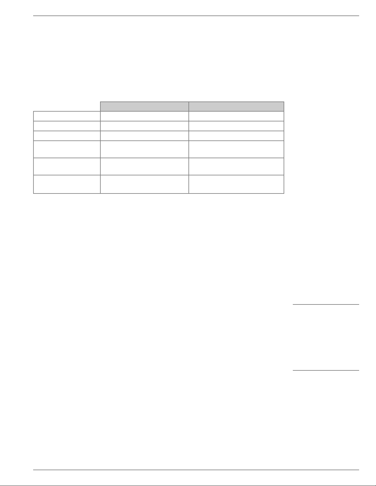
KRYOS
is designed for full operational service during a power failure, including full solenoid
KRYOS
is designed for full operational service during a power failure, including full solenoid
valve operation. The battery back-up system can be ordered from Taylor-Wharton
and should be factory installed.
Differences Between the Regular KRYOS and the Battery
Backed KRYOS
Please see the chart below for the differences between the two systems.
Table 2: Differences KRYOS & KRYOS with Battery Back-up Option
Regular KRYOS Battery Backed KRYOS
Solenoid Valve
24 VAC solenoid 12 VDC solenoid
Wall Transformer
24 VAC 16.5 VAC
Battery
None 17amp-hour
Battery Extension
Cable
None Connects battery to control board
Software
LABS 20K-80K – V9.22 K-Series and LABS 94K – V4.22B
LABS 20K-80K
Control Board (1)
Black 2-pin solenoid valve
plug
Red 2-pin solenoid valve plug &
Red 3-pin battery plug
(1) The control board for the battery back-up is quite different than the control board for the regular
KRYOS in that a number of parts are either removed or changed. The best check is a look for the
3 pin battery plug or press menu 6.4 and see if the software version has “B” behind it for battery
back-up.
Operation
The software is designed such that if power is lost and a battery-backed control is
in place, the control detects the loss of power and continues to operate from the
battery. If power is lost, a “Battery Back-up” message appears on the display, the
alarm beeper sounds and the red LED starts to flash. After a short period of time
(approximately 10 seconds) the display will go dark to conserve power, however the
red LED will continue to flash and the beeper will continue to sound until it is muted.
The display can be brought back at any time by pressing any button on the front
panel.
The control will continue to monitor the system, record logs and operate the valve
until the battery runs too low. Original specifications required that the battery run,
fully operational, for at least 72 hours. Battery back-up mode is treated by the
control as an alarm condition. This means that the remote alarm will be triggered
after a period of time as defined by the user.
The DC solenoid valve requires that the battery be connected for the system to work
properly. If the battery is disconnected or completely discharged the valve operation
and the control operation may be affected. In particular, if the control is calling
for a fill, the solenoid will be called to open. Opening the solenoid valve takes a
substantial amount of current. The valve will cycle on and off. If the batter-backed
control keeps turning itself on and then off, try recharging the battery by following
the steps below.
Battery Charging: The KRYOS control has a circuit that trickle charges the battery.
This provides a fully charged battery for the times when it is needed yet keeps it from
being damaged by overcharging. If the battery should become discharged, the
following steps should be followed to charge it.
NOTE:
We strongly recommend
that the remote alarm is
connected to a building
alarm system or a
dialer. This insures that
someone is notified if an
error condition persists.
valve operation. The battery back-up system can be ordered from Taylor-Wharton
and should be factory installed.
Differences Between the Regular KRYOS and the Battery
Backed KRYOS
Please see the chart below for the differences between the two systems.
Table 2: Differences KRYOS & KRYOS with Battery Back-up Option
Regular KRYOS Battery Backed KRYOS
24 VAC solenoid 12 VDC solenoid
Solenoid Valve
Wall Transformer
Battery
Battery Extension
Cable
Software
Control Board (1)
24 VAC 16.5 VAC
None 17amp-hour
None Connects battery to control board
LABS 20K-80K – V9.22 K-Series and LABS 94K – V4.22B
LABS 20K-80K
Black 2-pin solenoid valve
plug
Red 2-pin solenoid valve plug &
Red 3-pin battery plug
KRYOS
(1) The control board for the battery back-up is quite different than the control board for the regular
KRYOS in that a number of parts are either removed or changed. The best check is a look for the
3 pin battery plug or press menu 6.4 and see if the software version has “B” behind it for battery
back-up.
Operation
The software is designed such that if power is lost and a battery-backed control is
in place, the control detects the loss of power and continues to operate from the
battery. If power is lost, a “Battery Back-up” message appears on the display, the
alarm beeper sounds and the red LED starts to flash. After a short period of time
(approximately 10 seconds) the display will go dark to conserve power, however the
red LED will continue to flash and the beeper will continue to sound until it is muted.
The display can be brought back at any time by pressing any button on the front
panel.
The control will continue to monitor the system, record logs and operate the valve
until the battery runs too low. Original specifications required that the battery run,
fully operational, for at least 72 hours. Battery back-up mode is treated by the
control as an alarm condition. This means that the remote alarm will be triggered
after a period of time as defined by the user.
The DC solenoid valve requires that the battery be connected for the system to work
properly. If the battery is disconnected or completely discharged the valve operation
and the control operation may be affected. In particular, if the control is calling
for a fill, the solenoid will be called to open. Opening the solenoid valve takes a
substantial amount of current. The valve will cycle on and off. If the batter-backed
control keeps turning itself on and then off, try recharging the battery by following
the steps below.
NOTE:
We strongly recommend
that the remote alarm is
connected to a building
alarm system or a
dialer. This insures that
someone is notified if an
error condition persists.
Battery Charging: The KRYOS control has a circuit that trickle charges the battery.
This provides a fully charged battery for the times when it is needed yet keeps it from
being damaged by overcharging. If the battery should become discharged, the
following steps should be followed to charge it.
23
Page 26

KRYOS
KRYOS
t Turn the control off using the Power button on the front panel of the KRYOS.
Even though the control is turned off, the battery will still be recharged.
t Check all connections to the KRYOS, especially the harness plug, the wall
transformer and the battery extension cable. The wall transformer should be
plugged into the wall.
t Wait for 30-60 minutes. After this time period, the battery should have enough
power to run the control and continue charging the battery.
Battery Life
The life of the battery will vary according to many factors including use and storage
temperature. The lead-acid batteries have an expected life of 3 to 5 years. For full
functionality of your Cryostorage System we recommend that the lead-acid battery
be changed every 3 years.
INTERFACE SOFTWARE
Optional software (CRYOCOM) is available which allows a computer system to
communicate with KRYOS through the serial port on the freezer. The software
provides the capability to download the logs, review control settings, change control
settings and perform system functions such as open/close the solenoid valve, mute
the alarm, etc. Contact Taylor-Wharton for details. Please have your Cryostorage
System serial number, KRYOS serial number and version number as it appears in
ABOUT THIS CONTROL (MENU, 6, 4).
Figure 7.0 Optional computer software program “CRYOCOM” works with
the KRYOS software system to control and monitor each unit.
The KRYOS control is also compatible with the SQR-1 Sequence that provides
sequence filling at multiple freezer locations.
Making Adjustments to the KRYOS Sensor Assembly
Table 3: KRYOS Sensor Assembly Factory Settings
CRYOSTORAGE
SYSTEM
LOW LEVEL
ALARM
START
FILL
STOP
FILL
HIGH LEVEL
ALARM
10K, 24K, 38K 2" 3" 6" 7"
LABS 20, 38, 40, 80 2" 3" 5" (at carousel) 6"
LABS 94 5" 6" 9" (at carousel 10"
*Based on standard 7-thermistor
The sensor assembly is preset at the factory for vapor phase storage. If adjustments
need to be made, the following procedure will simplify the process.
t Turn the control off using the Power button on the front panel of the KRYOS.
Even though the control is turned off, the battery will still be recharged.
t Check all connections to the KRYOS, especially the harness plug, the wall
transformer and the battery extension cable. The wall transformer should be
plugged into the wall.
t Wait for 30-60 minutes. After this time period, the battery should have enough
power to run the control and continue charging the battery.
Battery Life
The life of the battery will vary according to many factors including use and storage
temperature. The lead-acid batteries have an expected life of 3 to 5 years. For full
functionality of your Cryostorage System we recommend that the lead-acid battery
be changed every 3 years.
INTERFACE SOFTWARE
ciSmart Com is an optional product that communicates with the KRYOS control system
Optional software (CRYOCOM) is available which allows a computer system to
through the serial port on the freezer. The ciSmart Com product provides easy access to
communicate with KRYOS through the serial port on the freezer. The software
freezer operational data. Both local and global access can be provided through a network
provides the capability to download the logs, review control settings, change control
connection and additional feature such as data storage, reporting, graphing and status/
settings and perform system functions such as open/close the solenoid valve, mute
DODUPQRWLÀFDWLRQLVDYDLODEOH3OHDVHKDYH\RXU&U\RVWRUDJH6\VWHPVHULDOQXPEHU
the alarm, etc. Contact Taylor-Wharton for details. Please have your Cryostorage
KRYOS serial number and version number as it appears in ABOUT THIS CONTROL
System serial number, KRYOS serial number and version number as it appears in
(MENU, 6, 4).
ABOUT THIS CONTROL (MENU, 6, 4).
24
Figure 7.0 Optional computer software program “CRYOCOM” works with
The KYROS control is also compatible with SQR-1 Fill Sequencer that provides
The KRYOS control is also compatible with the SQR-1 Sequence that provides
VHTXHQWLDOÀOOLQJRIPXOWLSOHIUHH]HUV
sequence filling at multiple freezer locations.
Making Adjustments to the KRYOS Sensor Assembly
Table 3: KRYOS Sensor Assembly Factory Settings
CRYOSTORAGE
10K, 24K, 38K 2" 3" 6" 7"
LABS 20, 38, 40, 80 2" 3" 5" (at carousel) 6"
*Based on standard 7-thermistor
The sensor assembly is preset at the factory for vapor phase storage. If adjustments
need to be made, the following procedure will simplify the process.
the KRYOS software system to control and monitor each unit.
SYSTEM
LABS 94 5" 6" 9" (at carousel 10"
LOW LEVEL
ALARM
START
FILL
STOP
FILL
HIGH LEVEL
ALARM
Page 27
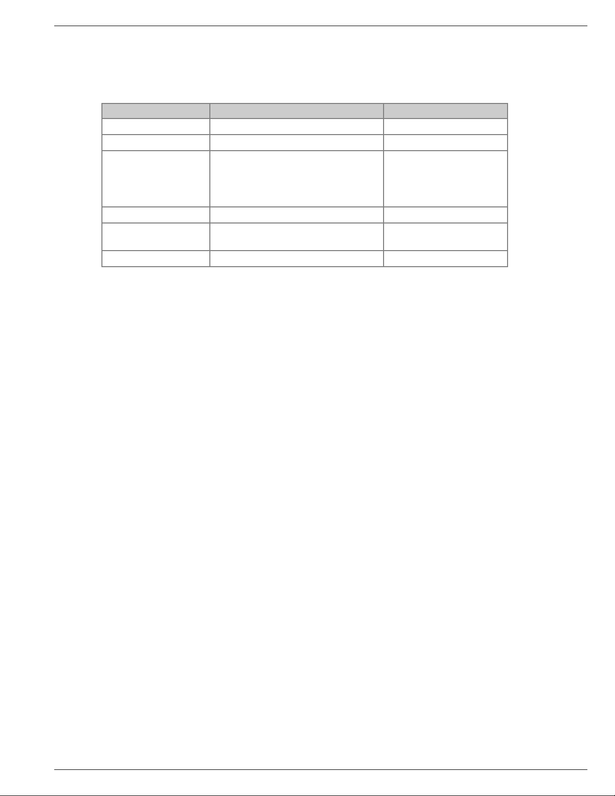
KRYOS
KRYOS
KRYOS
The KRYOS control installed on the Taylor-Wharton Cryostorage units operates with
specially designed software to match the design characteristics of the different LABS
and K-Series units. Refer to the chart below to see the versions and their difference.
Table 4: Software Version Differences
SOFTWARE VERSIONS KRYOS 4.22 KRYOS 9.22
MODELS
All K-Series and LABS 94K LABS 20K, 38K, 40K, 80K
Level Readings
1 in. (25.4 mm) increments
Default
Start Fill / Stop Fill
K-Series - 3 in. / 6 in.
(76.2 mm / 152.4 mm)
LABS 94K - 6 in. / 9 in.
(152.4 mm / 228.6 mm)
3 in. / 5 in.
Default Auto Defog
15 seconds 20 seconds
Offset Value
Adjustable (allows the sensor
assembly to be raised)
Preset (sensor assembly
located at factory setting)
Units of Measure
English/Metric English
Version 9.22 Level Reading
The sensor tube on the LABS 20K, 38K, 40K, AND 80K systems are installed
through the annular space (vacuum) and takes a curve near the bottom. The sensor
assembly accommodates this curve. Versions 9.22 software computes the non-
linearity of the sensor assembly position. This software version displays the following
readings on the KRYOS display.
t Thermistor #1 uncovered; KRYOS will display “<2.8 in.”
t Thermistor #1 covered; KRYOS will display “2.8 / 3.0 in.”
t Thermistor #2 covered; KRYOS will display “3.0 / 3.3 in.”
t Thermistor #3 covered; KRYOS will display “3.3 / 4.0 in.”
t Thermistor #4 covered; KRYOS will display “4.0 / 5.0 in.”
t Thermistor #5 covered; KRYOS will display “5.0 / 6.0 in.”
t Thermistor #6 covered; KRYOS will display “6.0 / 7.0 in.”
t Thermistor #7 covered; KRYOS will display “>7.0 in.”
Other Changes
t The offset has been removed in this version of software to handle the non-
linearity of the sensor when installed in the refrigerator.
t Metric readings have been removed in this version of the software.
Recommendations for Liquid Storage
If the LABS 20K, 38K, 40K, 80K will be used to store the product in Liquid Nitrogen,
two options are available:
1. Version 4.0 software can be installed into the KRYOS to provide the offset.
This allows the control to recognize that the sensor has been raised off the
floor of the refrigerator so that the correct level readings can be displayed.
(P/N: EPROM-KRYOS40)
2. The optional 4-thermistor sensor can be purchased from Taylor-Wharton to
work with the KRYOS control (works in either version of the software). This
sensor allows the user to physically place the start fill and stop fill sensor at the
appropriate level locations in the refrigerator. The KRYOS then displays the level
as High, Normal or Low (P/N: 5140-1163-4T)
The KRYOS control installed on the Taylor-Wharton Cryostorage units operates with
specially designed software to match the design characteristics of the different LABS
and K-Series units. Refer to the chart below to see the versions and their difference.
Table 4: Software Version Differences
SOFTWARE VERSIONS KRYOS 4.22 KRYOS 9.22
MODELS
Level Readings
Default
Start Fill / Stop Fill
Default Auto Defog
Offset Value
Units of Measure
All K-Series and LABS 94K LABS 20K, 38K, 40K, 80K
1 in. (25.4 mm) increments
K-Series - 3 in. / 6 in.
(76.2 mm / 152.4 mm)
LABS 94K - 6 in. / 9 in.
(152.4 mm / 228.6 mm)
15 seconds 20 seconds
Adjustable (allows the sensor
assembly to be raised)
English/Metric English
3 in. / 5 in.
Preset (sensor assembly
located at factory setting)
Version 9.22 Level Reading
The sensor tube on the LABS 20K, 38K, 40K, AND 80K systems are installed
through the annular space (vacuum) and takes a curve near the bottom. The sensor
assembly accommodates this curve. Versions 9.22 software computes the nonlinearity of the sensor assembly position. This software version displays the following
readings on the KRYOS display.
t Thermistor #1 uncovered; KRYOS will display “<2.8 in.”
t Thermistor #1 covered; KRYOS will display “2.8 / 3.0 in.”
t Thermistor #2 covered; KRYOS will display “3.0 / 3.3 in.”
t Thermistor #3 covered; KRYOS will display “3.3 / 4.0 in.”
t Thermistor #4 covered; KRYOS will display “4.0 / 5.0 in.”
t Thermistor #5 covered; KRYOS will display “5.0 / 6.0 in.”
t Thermistor #6 covered; KRYOS will display “6.0 / 7.0 in.”
t Thermistor #7 covered; KRYOS will display “>7.0 in.”
Other Changes
t The offset has been removed in this version of software to handle the non-
linearity of the sensor when installed in the refrigerator.
t Metric readings have been removed in this version of the software.
Recommendations for Liquid Storage
If the LABS 20K, 38K, 40K, 80K will be used to store the product in Liquid Nitrogen,
two options are available:
1. Version 4.0 software can be installed into the KRYOS to provide the offset.
This allows the control to recognize that the sensor has been raised off the
floor of the refrigerator so that the correct level readings can be displayed.
(P/N: EPROM-KRYOS40)
4.xx
2. The optional 4-thermistor sensor can be purchased from Taylor-Wharton to
work with the KRYOS control (works in either version of the software). This
sensor allows the user to physically place the start fill and stop fill sensor at the
appropriate level locations in the refrigerator. The KRYOS then displays the level
as High, Normal or Low (P/N: 5140-1163-4T)
25
Page 28

KRYOS
KRYOS
To make adjustments to a sensor assembly in a refrigerator filled with LN2, the
following procedure can be used:
t Measure the LN
2
liquid level in the refrigerator.
t Take this measured level and subtract the offset to determine how many sensors
should be in liquid.
a. Remove sensors.
b. Fill to correct level and turn off Liquid supply.
c. Eg. Level is to be 15 in. (381 mm) and sensor number 6 is to be Stop Fill.
15 in. (381 mm) – 6 in. (152.4 mm) = 9 in. (238.6 mm) offset. Set Offset
(MENU, 2).
t Go to “Test Level Sensor” through the KRYOS menu (MENU, 2, 1). “L” means a
sensor is in liquid while “G” means a sensor is in gas.
t Move the sensor up or down so that the appropriate numbers of sensors are in
liquid (read “L”).
t Get back to the KRYOS main screen and the level indicated should match the
physically measured reading.
The Sensor Offset, the START FILL and the STOP FILL can all be set through the
KRYOS menu system (MENU, 2).
1.0 in. (25.4 mm)
ICS Platform
Factory Settings
Offset 0.0 in.
Lid Closed Temp. (-140°C)
Lid Open Temp. (-80°C)
High Alarm Sensor
FACTORY Settings
Thermistor Array
23.0 in. (584 mm)
Full Level Sensor
Thermistors - Sensors
Low Level Sensor
Ex. Low Level Sensor
7.0 in. (178 mm)
Perforated Stainless Steel
Sensor Tube
Temperature Thermocouple
Top of Freezer Tub
8
7
6
5
4
3
2
1
Figure 8.0 Sensor Positioning
To make adjustments to a sensor assembly in a refrigerator filled with LN2, the
following procedure can be used:
t Measure the LN
t Take this measured level and subtract the offset to determine how many sensors
should be in liquid.
a. Remove sensors.
b. Fill to correct level and turn off Liquid supply.
c. Eg. Level is to be 15 in. (381 mm) and sensor number 6 is to be Stop Fill.
t Go to “Test Level Sensor” through the KRYOS menu (MENU, 2, 1). “L” means a
sensor is in liquid while “G” means a sensor is in gas.
t Move the sensor up or down so that the appropriate numbers of sensors are in
liquid (read “L”).
t Get back to the KRYOS main screen and the level indicated should match the
physically measured reading.
The Sensor Offset, the START FILL and the STOP FILL can all be set through the
KRYOS menu system (MENU, 2).
liquid level in the refrigerator.
2
15 in. (381 mm) – 6 in. (152.4 mm) = 9 in. (238.6 mm) offset. Set Offset
(MENU, 2).
Top of Freezer Tub
Temperature Thermocouple
ICS Platform
23.0 in. (584 mm)
7.0 in. (178 mm)
1.0 in. (25.4 mm)
8
7
6
5
4
3
2
1
Factory Settings
Offset 0.0 in.
Lid Closed Temp. (-140°C)
Lid Open Temp. (-80°C)
Perforated Stainless Steel
Sensor Tube
Thermistor Array
FACTORY Settings
High Alarm Sensor
Full Level Sensor
Thermistors - Sensors
Low Level Sensor
Ex. Low Level Sensor
26
Figure 8.0 Sensor Positioning
Page 29

KRYOS
KRYOS
KRYOS
Removing/Installing the Solenoid Valve
The LN2 and power must be turned off before beginning work on the solenoid valve.
For For All K-Series and LABS Units
Disconnect only the solenoid valve lead connection from the back of controller
board.
To remove the solenoid valve, loosen the compression fitting that connects the
plumbing tubing to fill tube. Unscrew the two (2) mounting screws that hold the
solenoid valve to the solenoid bracket. Then remove the solenoid valve and its
associated plumbing. Disconnect the plumbing from the inlet and outlet side of the
solenoid valve.
To install a new solenoid valve, attach the connecting plumbing to the inlet and
outlet connections of the valve using Teflon tape on tapered threads (3 wraps).
Attach the compression fitting to the fill tube first and then connect the compression
fitting to the elbow that is connected to the outlet side of the solenoid valve. Position
the solenoid valve onto the solenoid valve bracket and tighten the two (2) mounting
screws. Attach the solenoid valve lead connection to the controller board.
Controller Electrical Tests
If a controller is removed from the refrigerator for service, the liquid refrigerant
level must be maintained manually to protect stored product. The fill solenoid valve
will be inoperative with the controller removed. A flexible fill line terminated with
a phase separator may be used periodically through the open refrigerator lid to
conduct manual fill operations until automatic operation is restored.
Sensor Probes. The sensor probes used to detect liquid level by Taylor-Wharton
controllers are temperature-sensitive resistors called “thermistors.” Their resistance
to electrical current flow changes greatly with their temperature.
t At Room Temperature ....2 ohms to 10 ohms
t In Cold Nitrogen Gas ....8 K ohms to 18 K ohms
t In Liquid Nitrogen .........18 K ohms to 35K ohms
Controller Logic. The liquid level controllers read the values of the sensors as
indications of liquid level. The function of a sensor, and its value, are interpreted
by solid-state logic circuitry to set normal operating, fill, fill termination, and alarm
conditions. In addition, the refrigerator temperature is monitored and an alarm is
triggered if the temperature raises above a pre-determined point.
t From cold gas to liquid ..Resistance greater than 22K ohms.
t From liquid to cold gas ..Resistance less than 16K ohms.
t Defective Sensor ............Resistance greater than 50K ohms, or less that 5 ohms.
15 K ohms to 39 K ohms
14 K
14K
48K
27
Page 30

Sensor Plug Schematic
KRYOS
KRYOS
Sensor Plug Schematic
1234567 8910 11 12
12
FREEZE-GUARD
SENSOR
SENSOR ASSEMBLIES - 12 PIN MOLEX PLUG
THERMOCOUPLE 1 OR 2
Check Continuity
SOLENOID VALVE
Check Continuity
and Energize with
24VAC
LID SWITCH
Check
Continuity
Operate Switch
WALL TRANSFORMER
POWER SUPPLY
24VAC
HAL
SpF
LA
FG
NO
C
StF
NC
RA
=
=
=
=
=
=
=
=
=
High Level Alarm
Stop Fill
Low Alarm
Freeze Guard
Normally Open
Common
Start Fill
Normally Closed
Remote Alarm
Orange
White
Yellow
Black
Red
Blue
Purple
Brown
Grey
Green
=
=
=
=
=
=
=
=
=
=
Or
Wh
Ye
Bk
Rd
Bl
Pu
Br
Gy
Gr
CO
CP
Contacts
-+
1
2
3
4
5
6
7
8
9
10
11
12
empty
empty
empty
empty
empty
empty
Or C
Wh H AL
Ye SpF
Bk StF
Rd LA
Br C
bk FG
bk FG
Ye
BL
Rd
BK C
empty
Gy
Or
Pu
Wh
Br C
Bk C
Gr
Ye
Pu
Rd
empty
empty
Bl
Or
Gy
Wh
Br C
OPTIONAL
4 LEVEL
SENSOR
STANDARD
FREEZE-GUARD
7 LEVEL +1*
PIN
#
OPTIONAL
8 LEVEL
SENSOR
Figure 9.0 Pin View Schematics
SENSOR ASSEMBLIES - 12 PIN MOLEX PLUG
PIN
#
1
2
3
4
5
6
7
8
9
10
11
12
HAL
SpF
LA
FG
NO
C
StF
NC
RA
12
1234567 8910 11 12
STANDARD
FREEZE-GUARD
7 LEVEL +1*
bk FG
bk FG
Ye
BL
Rd
BK C
empty
Gy
Or
Pu
Wh
Br C
=
=
=
=
=
=
=
=
=
OPTIONAL
8 LEVEL
High Level Alarm
Stop Fill
Low Alarm
Freeze Guard
Normally Open
Common
Start Fill
Normally Closed
Remote Alarm
SENSOR
Bk C
Gr
Ye
Pu
Rd
empty
empty
Bl
Or
Gy
Wh
Br C
Or
Wh
Ye
Bk
Rd
Bl
Pu
Br
Gy
Gr
OPTIONAL
4 LEVEL
SENSOR
empty
empty
empty
empty
empty
empty
Or C
Wh H AL
Ye SpF
Bk StF
Rd LA
Br C
Orange
=
White
=
Yellow
=
Black
=
Red
=
Blue
=
Purple
=
Brown
=
Grey
=
Green
=
CO
CP
THERMOCOUPLE 1 OR 2
Check Continuity
FREEZE-GUARD
SOLENOID VALVE
Check Continuity
and Energize with
Figure 9.0 Pin View Schematics
SENSOR
24VAC
LID SWITCH
Continuity
Operate Switch
Check
WALL TRANSFORMER
POWER SUPPLY
24VAC
Contacts
-+
28
Page 31

KRYOS
Plumbing Assembly
Solenoid(Valve
90(deg(Elbow
90(deg(Elbow
Relief(Valve(Tube
Female(Connector
Relief(Valve
Strainer
Reducer
Male(Branch
Tee
Male(Branch
Tee
Freeze@Guard
Sensor
Figure 10.0 LABS Plumbing Assembly
Figure 11.0 K-Series 10K and 24K Plumbing Assembly
&,0)&$'%&
;7:6078:8
-->0-866
"&$
<>7<0968;
--7/:
?6"%+
:;8;7>6<
-9/>27/:2-
%"$%!"*
<???0?6:7
--80-7/:2-78-3>8<886>
)&
<=7?0?69=
----9/>7/:
(&!$&
=<97076>6
-9/>2-
"!"*)1
:60??6
--:6
#"%$$(%&
:;7;7;?6
-9/>27/:2-97<
"!"*
<?790?6==
--766-.8;2
%$$(%&
=9;;0:=7811
-8?;9/>2
"%$$(%&
:;=67?<=11
-7/:2-
(&(
<>7<0668;11
-7/:2.
Plumbing Assembly
Freeze-Guard Sensor
Solenoid Valve
KRYOS
Figure 10.0 LABS Plumbing Assembly
Male Branch Tee
90 Deg Elbow
CGA Connector
Street Tee
Male Connector
Reducer
Strainer
Relief Valve Tube
Female Connector
Relief Valve
Figure 10.0 LABS Plumbing Assembly
Freeze-Guard
Sensor
Compression Fitting
Male Branch Tee
Male Connector
Figure 11.0 K-Series 10K and 24K Plumbing Assembly
Relief Valve Tube
Solenoid Valve
Male Connector
Male Branch Tee
Female Connector
Relief Valve
90 Deg Elbow
From Liquid
Nitrogen Supply
29
Page 32
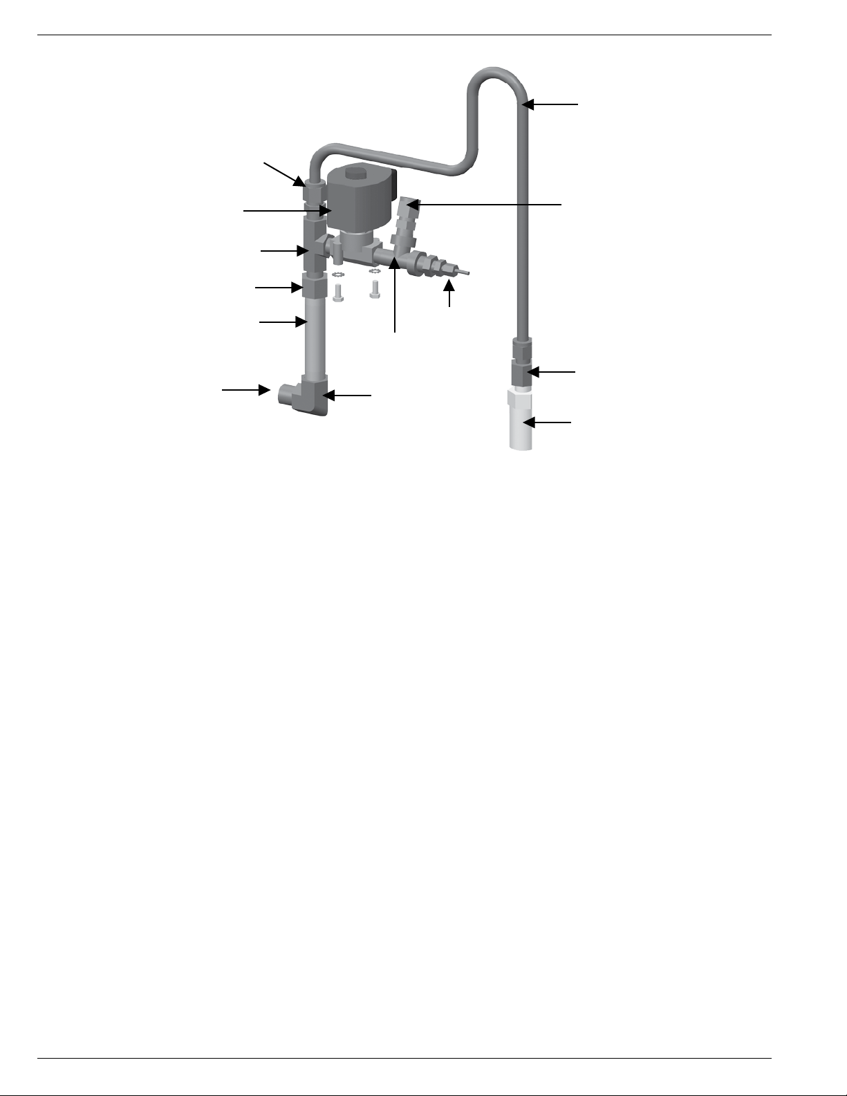
Figure 12.0 38K Plumbing Assembly
KRYOS
KRYOS
Figure 12.0 38K Plumbing Assembly
TROUBLESHOOTING
Symptoms
The key to troubleshooting your KRYOS controller and your cryostorage system is to
determine which component in the system is the source of the problem. Determine if
the problem is occurring in any of the following subsystems: Supply Vessel, Transfer
Line, Power Source, Temperature, Level Sensing, Security, Lid Switch, Solenoid Valve,
Control Display, Alarm System, Communications. After determining which sub-
system is having the problem, isolate the problem further by performing sub-system
tests. Once the problem is isolated and defined, it will be easier to solve.
Controller Will Not Turn ON
1. Press POWER button. If display is blank and dark go to next step.
2. Check all connections. Start with jacks at the foot of the controller. Pay special
attention to jacks labeled “POWER”. Wall transformer must be plugged into an
outlet providing AC voltage between 100 and 130 to deliver AC voltage 21 to
30 to the back of the freezer.
3. If available, check your Battery back-up and make sure it is working properly.
Troubleshoot that as needed.
Relief Valve Tube
Male Connector
Solenoid Valve
Male Branch Tee
Female Pipe Fitting
From Liquid
Nitrogen Supply
Nipple
Freeze-Guard
Street Tee
90 Deg Elbow
Figure 12.0 38K Plumbing Assembly
Sensor
Male Connector
Female Connector
Relief Valve
TROUBLESHOOTING
Symptoms
The key to troubleshooting your KRYOS controller and your cryostorage system is to
determine which component in the system is the source of the problem. Determine if
the problem is occurring in any of the following subsystems: Supply Vessel, Transfer
Line, Power Source, Temperature, Level Sensing, Security, Lid Switch, Solenoid Valve,
Control Display, Alarm System, Communications. After determining which subsystem is having the problem, isolate the problem further by performing sub-system
tests. Once the problem is isolated and defined, it will be easier to solve.
30
Controller Will Not Turn ON
1. Press POWER button. If display is blank and dark go to next step.
to the back of the frezer.
2. Check all connections. Start with jacks at the foot of the controller. Pay special
attention to jacks labeled “POWER”. Wall transformer must be plugged into an
outlet providing AC voltage between 100 and 130 to deliver AC voltage 21 to
30 to the back of the freezer.
3. If available, check your Battery back-up and make sure it is working properly.
Troubleshoot that as needed.
Page 33

KRYOS
KRYOS
KRYOS
Indicates High Liquid Level
1. Determine actual liquid level using a dipstick. Select MENU, LEVEL SENSING,
TEST LEVEL SENSORS. An “L” or “G” will indicate individual thermistor status.
“L” meaning that the thermistor is submerged in liquid and “G” indicates that
the thermistor is in cold Gas. Determine the pressure, and remaining liquid level
in the supply cylinder (15 to 22 psi). A fill solenoid valve that freezes (or sticks)
open will typically empty the supply cylinder. Replace solenoid valve if it has
failed even once.
2. Liquid level is sensed by thermistors located in a sensor tube. If the sensor tube
is blocked or iced at the top, the liquid level in the sensor tube may not rise and
fall at the same rate as the liquid level in the freezing chamber. Make sure the
sensor tube is not obstructed.
3. The pool of LN
2
can become turbulent during a fill. Bubbling and splashing can
be amplified by the rack arrangement. The deeper the pool, the more turbulent
the surface of the pool will be during a fill. The turbulence of the pool surface
can splash on the X-High thermistor and cause a false high alarm. Reduce the
splashing.
4. Confirm that sensor assembly is responding to changing liquid level with a dip-
test.
t Mark the sensor assembly at top of tube to assure re-assembly.
t Close liquid supply valve at source.
t Remove sensor assembly from sensor tube. DO NOT FORCE. Fill solenoid
valve should open and LOW LEVEL alarm should be activated.
t Select MENU, LEVEL SENSING, TEST LEVEL SENSORS. An “L” or “G” will
indicate individual thermistor status (L = Liquid and G = Gas).
t Dip each thermistor in succession into LN
2
Observe the controller display
noting that each thermistor changes from “G” to “L” as each is submerged.
Response time may vary.
t Return to the main menu and submerge the START FILL THERMISTOR IN
LIQUID. Note that the low level alarm ceases, fill solenoid valve is still open.
Control is flashing FILLING.
t Manually press STOP button and note that the fill solenoid valve closes.
t Press FILL button to re-open fill solenoid valve.
t Continue to lower the sensor until the STOP FILL thermistor is immersed in
the LN
2
. The fill should stop after a confirming (CHECK) SPLASH GUARD
period.
t Simulate an over fill by lowering the next thermistor into the LN
2
. HIGH
LEVEL alarm should sound with 10 seconds.
t Re-install sensor assembly and thermocouple into sensor tube as before.
Open supply valve on LN
2
supply.
Indicates High Liquid Level
1. Determine actual liquid level using a dipstick. Select MENU, LEVEL SENSING,
TEST LEVEL SENSORS. An “L” or “G” will indicate individual thermistor status.
“L” meaning that the thermistor is submerged in liquid and “G” indicates that
the thermistor is in cold Gas. Determine the pressure, and remaining liquid level
in the supply cylinder (15 to 22 psi). A fill solenoid valve that freezes (or sticks)
open will typically empty the supply cylinder. Replace solenoid valve if it has
failed even once.
2. Liquid level is sensed by thermistors located in a sensor tube. If the sensor tube
is blocked or iced at the top, the liquid level in the sensor tube may not rise and
fall at the same rate as the liquid level in the freezing chamber. Make sure the
sensor tube is not obstructed.
3. The pool of LN
can become turbulent during a fill. Bubbling and splashing can
2
be amplified by the rack arrangement. The deeper the pool, the more turbulent
the surface of the pool will be during a fill. The turbulence of the pool surface
can splash on the X-High thermistor and cause a false high alarm. Reduce the
splashing.
4. Confirm that sensor assembly is responding to changing liquid level with a diptest.
t Mark the sensor assembly at top of tube to assure re-assembly.
t Close liquid supply valve at source.
t Remove sensor assembly from sensor tube. DO NOT FORCE. Fill solenoid
valve should open and LOW LEVEL alarm should be activated.
t Select MENU, LEVEL SENSING, TEST LEVEL SENSORS. An “L” or “G” will
indicate individual thermistor status (L = Liquid and G = Gas).
t Dip each thermistor in succession into LN
Observe the controller display
2
noting that each thermistor changes from “G” to “L” as each is submerged.
Response time may vary.
t Return to the main menu and submerge the START FILL THERMISTOR IN
LIQUID. Note that the low level alarm ceases, fill solenoid valve is still open.
Control is flashing FILLING.
t Manually press STOP button and note that the fill solenoid valve closes.
t Press FILL button to re-open fill solenoid valve.
t Continue to lower the sensor until the STOP FILL thermistor is immersed in
the LN
. The fill should stop after a confirming (CHECK) SPLASH GUARD
2
period.
t Simulate an over fill by lowering the next thermistor into the LN
LEVEL alarm should sound with 10 seconds.
t Re-install sensor assembly and thermocouple into sensor tube as before.
Open supply valve on LN
supply.
2
. HIGH
2
31
Page 34

KRYOS
KRYOS
Indicates Low LN2 Supply
When the START FILL thermistor is uncovered, the controller calls for the fill solenoid
valve to open. If the STOP FILL thermistor is not covered with LN
2
in the pre-
determined amount of time, the controller is programmed to interpret this as a LN
2
supply shortage.
1. Check contents gauge and pressure gauge of supply cylinder. Both liquid
contents and pressure (15 to 22 psi) are required to complete a fill.
2. Confirm that no other transfer hose or apparatus is attached to the supply
cylinder. Either could compromise adequate tank pressure required to complete
a fill in 30 minutes.
t Check the distance that the LN
2
must travel to reach the freezer. Observe
the time it takes for Liquid LN2 to reach the Freezer through the usual piping
conditions (Pipe-Temperature at start fill). Liquid should be entering the
chamber within 4 minutes under normal (usual) line temperature conditions.
t Distances over 6 feet (1.83 m) without a gas by-pass are discouraged due to
excessive boil off. Un-insulated fill line for the last 4 feet are encouraged to
drive down vapor temperatures in the freezing chamber during each fill.
t A “Keep-Cold” or a “Keep-Full” device are almost always needed on an LN
2
pipeline, whether the pipe is Vacuum Jacketed or Foam Insulated.
3. Confirm that the solenoid valve is open when a fill is called for.
t If no flow is detected, the solenoid valve is not getting the signal to open, or
it is opening and there is a blockage in the line. Check the connections on
the leads near the solenoid itself, as well as the connector at the controller.
t Confirm that the wires have not been pinched, creating a short circuit.
4. If a longer fill time is desired, change the setting by selecting: MENU, SYSTEM
ALARMS, LN
2
SUPPLY ALARM.
Indicates Open Sensor
1. Normally, this message is associated with a loose plug or connector. Check the
connection at the foot of the controller labeled SENSORS.
2. If the problem persists, the sensor assembly may need to be replaced. To
determine this select: MENU, LEVEL SENSING, TEST LEVEL SENSORS. An “L”,
“G”, or “O” (open) will indicate individual thermistor status.
3. Thermocouple is not repairable. Replace from stock.
Temperature Reading 10 to 20 Degrees Warm
t Prepare an ice water slurry with crushed ice and tap water. Dip or pour LN2
into a styrofoam cup to prepare an LN
2
bath. Calibrate the controller. Select
MENU, TEMPERATURE, CALIBRATE TEMPERATURE. Follow the on-screen
instructions. Hold the thermocouple in each bath until the control completes its
self-calibration.
t Make sure the thermocouple is clean and dry before and after each bath.
t Reposition the thermocouple at the elevation the customer wants to monitor or
control.
Indicates Low LN2 Supply
When the START FILL thermistor is uncovered, the controller calls for the fill solenoid
valve to open. If the STOP FILL thermistor is not covered with LN
determined amount of time, the controller is programmed to interpret this as a LN
supply shortage.
1. Check contents gauge and pressure gauge of supply cylinder. Both liquid
2. Confirm that no other transfer hose or apparatus is attached to the supply
in the pre-
2
contents and pressure (15 to 22 psi) are required to complete a fill.
cylinder. Either could compromise adequate tank pressure required to complete
a fill in 30 minutes.
t Check the distance that the LN
t Distances over 6 feet (1.83 m) without a gas by-pass are discouraged due to
t A “Keep-Cold” or a “Keep-Full” device are almost always needed on an LN
the time it takes for Liquid LN2 to reach the Freezer through the usual piping
conditions (Pipe-Temperature at start fill). Liquid should be entering the
chamber within 4 minutes under normal (usual) line temperature conditions.
must travel to reach the freezer. Observe
2
excessive boil off. Un-insulated fill line for the last 4 feet are encouraged to
drive down vapor temperatures in the freezing chamber during each fill.
pipeline, whether the pipe is Vacuum Jacketed or Foam Insulated.
2
2
3. Confirm that the solenoid valve is open when a fill is called for.
4. If a longer fill time is desired, change the setting by selecting: MENU, SYSTEM
Indicates Open Sensor
1. Normally, this message is associated with a loose plug or connector. Check the
2. If the problem persists, the sensor assembly may need to be replaced. To
3. Thermocouple is not repairable. Replace from stock.
Temperature Reading 10 to 20 Degrees Warm
t Prepare an ice water slurry with crushed ice and tap water. Dip or pour LN2
t Make sure the thermocouple is clean and dry before and after each bath.
t Reposition the thermocouple at the elevation the customer wants to monitor or
t If no flow is detected, the solenoid valve is not getting the signal to open, or
t Confirm that the wires have not been pinched, creating a short circuit.
it is opening and there is a blockage in the line. Check the connections on
the leads near the solenoid itself, as well as the connector at the controller.
ALARMS, LN
SUPPLY ALARM.
2
connection at the foot of the controller labeled SENSORS.
determine this select: MENU, LEVEL SENSING, TEST LEVEL SENSORS. An “L”,
“G”, or “O” (open) will indicate individual thermistor status.
into a styrofoam cup to prepare an LN
MENU, TEMPERATURE, CALIBRATE TEMPERATURE. Follow the on-screen
instructions. Hold the thermocouple in each bath until the control completes its
self-calibration.
control.
bath. Calibrate the controller. Select
2
32
Page 35

KRYOS
KRYOS
KRYOS
Fill Solenoid Cycles On and Off
KRYOS features a Freeze-Guard function whereby the valve open duration is limited,
allowed to shut for a short warm-up and then opened again. To confirm or change
the valve open duration:
t Select MENU, USER OPTIONS, CONTROL OPTIONS, FREEZE-GUARD
OPTIONS, VALVE OPEN DURATION.
If the controller detects that the valve is stuck in the open position (i.e., continues to
fill after the valve is de-energized), it will attempt to De-Ice the valve by causing a
rapid cycling of the valve in an attempt to dislodge the blockage.
t To activate or de-activate this feature: Select MENU, USER OPTIONS,
CONTROL OPTIONS, FREEZE-GUARD OPTIONS, VALVE DE-ICING.
Repeated cycling of the Solenoid Valve, excessive turbulence or a low battery could
be attributable to moisture invasion on the controller circuit board.
1. Check gasket seals.
2. Access control board and allow time to fully dry.
3. Check the 3-prong plug is connected. Check the battery connection to the
controller and to the wall. Check the charge on the battery.
4. Confirm the pressure of the supply vessel is less than 22 psi.
5. Watch the interface panel on the controller to verify if the Start and Stop Fill
cycles are repeating.
Fill Solenoid Makes Humming Noise
Turn fill valve on and off using the control panel. If humming continues, it should
continue to operate reliably. If the noise is excessive, replace solenoid valve.
Transformer Makes Humming Noise
This noise is a normal byproduct of most block transformers. The transformer has
a non-renewable internal fuse to protect the transformer output. If the noise is
excessive, replace the transformer.
Display = “Check”
The word CHECK will flash during periods of Splash-Guard protection. See page 29
for more information.
Lid Open Alarm
A lid switch is located on the front hinge. The proximity switch should actuate when
the hinge is opened and again when it is shut.
t Confirm that there is a ½” (12 mm) gap between the sensors.”
QCF (Quick Chill Feature) Will Not Operate
See LID OPEN ALARM
To activate or adjust times: Select MENU, USER OPTIONS, CONTROL OPTIONS,
LID/DEFOG SETTINGS, QUICK CHILL.
33
Page 36

KRYOS
Defog Feature Will Not Operate
See LID OPEN ALARM.
To activate or adjust times: Select MENU, USER OPTIONS, CONTROL OPTIONS,
LID/DEFOG SETTINGS, AUTO DE-FOG.
Push Buttons Will Not Respond
1. Check all ribbon cable connectors on back of display panel.
2. Moisture may have migrated into the sealed faceplate. Call Taylor-Wharton for
a Return Authorization. Refer to the Service and Maintenance Log on the last
page of this manual to get the contact information you will need to return any
equipment.
Liquid Level Readout is Incorrect
Liquid level is determined by a seven-thermistor assembly inside a protective
sensor tube. The user may adjust the desired START FILL elevations and STOP FILL
elevations for the pool of nitrogen with the confines of the four inches. The LOW
LEVEL ALARM is automatically assigned to the thermistor below the START FILL
assignment, and the HIGH LEVEL ALARM automatically reserves the thermistor
above the STOP FILL thermistor assignment. For this reason START FILL cannot
be assigned to thermistor number 1. Similarly, STOP FILL cannot be assigned to
thermistor number 7. The factory installs this seven thermistor assembly all the
way to the floor of the sensor tube, which positions thermistor number 1 at 1 in.
(25.4 mm) above the floor (i.e.; the first thermistor is offset from the floor
zero inches).
If you would like to stop the fill at a depth greater than seven inches from the
floor, the sensor assembly must physically be raised inside the sensor tube. The
distance that it has been raised becomes the new OFFSET and the controller
must be notified of this offset from the floor. The factory settings are START FILL
at 3 inches and STOP FILL at 5 inches, with an OFFSET of zero. If you want to
establish a START at 15 and STOP at 17, raise the sensor assembly 12 inches
(17 minus 5) and set the controller OFFSET to 12 by: Selecting MENU, LEVEL
SENSING, SET SENSOR OFFSET. The unit should begin filling. The EX-LOW LEVEL
sensor has been subjected to the gaseous condition and should sound an alarm
(O.K. to MUTE). Note that in this scenario, you have directed your LN
2
supply
to accomplish a 15 inch fill level. It may be necessary to stop the fill manually
and allow the supply vessel time to regain enough pressure to complete this
exceptionally long initial fill.
For Liquid Level information and senor positioning, refer to pages 25-26.
Power Failure Alarm
If power is interrupted, a note of the time and duration will be recorded in the log.
If the unit is not connected to a battery back-up or an external alarm, then no local
alarm will be sounded unless a high temperature is detected after power resumes. A
Remote Alarm will be triggered anytime the power is interrupted.
KRYOS
Defog Feature Will Not Operate
See LID OPEN ALARM.
To activate or adjust times: Select MENU, USER OPTIONS, CONTROL OPTIONS,
LID/DEFOG SETTINGS, AUTO DE-FOG.
Push Buttons Will Not Respond
1. Check all ribbon cable connectors on back of display panel.
2. Moisture may have migrated into the sealed faceplate. Call Taylor-Wharton for
Liquid Level Readout is Incorrect
Liquid level is determined by a seven-thermistor assembly inside a protective
sensor tube. The user may adjust the desired START FILL elevations and STOP FILL
elevations for the pool of nitrogen with the confines of the four inches. The LOW
LEVEL ALARM is automatically assigned to the thermistor below the START FILL
assignment, and the HIGH LEVEL ALARM automatically reserves the thermistor
above the STOP FILL thermistor assignment. For this reason START FILL cannot
be assigned to thermistor number 1. Similarly, STOP FILL cannot be assigned to
thermistor number 7. The factory installs this seven thermistor assembly all the
way to the floor of the sensor tube, which positions thermistor number 1 at 1 in.
(25.4 mm) above the floor (i.e.; the first thermistor is offset from the floor
zero inches).
a Return Authorization. Refer to the Service and Maintenance Log on the last
page of this manual to get the contact information you will need to return any
equipment.
If you would like to stop the fill at a depth greater than seven inches from the
floor, the sensor assembly must physically be raised inside the sensor tube. The
distance that it has been raised becomes the new OFFSET and the controller
must be notified of this offset from the floor. The factory settings are START FILL
at 3 inches and STOP FILL at 5 inches, with an OFFSET of zero. If you want to
establish a START at 15 and STOP at 17, raise the sensor assembly 12 inches
(17 minus 5) and set the controller OFFSET to 12 by: Selecting MENU, LEVEL
SENSING, SET SENSOR OFFSET. The unit should begin filling. The EX-LOW LEVEL
sensor has been subjected to the gaseous condition and should sound an alarm
(O.K. to MUTE). Note that in this scenario, you have directed your LN
to accomplish a 15 inch fill level. It may be necessary to stop the fill manually
and allow the supply vessel time to regain enough pressure to complete this
exceptionally long initial fill.
For Liquid Level information and senor positioning, refer to pages 25-26.
Power Failure Alarm
If power is interrupted, a note of the time and duration will be recorded in the log.
If the unit is not connected to a battery back-up or an external alarm, then no local
alarm will be sounded unless a high temperature is detected after power resumes. A
Remote Alarm will be triggered anytime the power is interrupted.
supply
2
34
Page 37

KRYOS
REPLACEMENT KRYOS CONTROLLER FIELD
INSTALLATION
For all LABS and 38K Cryostorage Units
1. Unplug Power from unit.
2. Close liquid nitrogen supply at valve.
3. Remove (4) Phillips head screws from rear of interface display box.
4. Remove controller face from interface display box.
5. Finish face removal by disconnecting plug and ground wire.
6. Remove (2) Phillips head screws from the old control located underneath the
tabletop.
7. Withdraw old controller from underneath table top, noting how the controller
body has been resting on outer upper head.
8. Unplug all connectors and wires and set panel aside.
9. Disconnect supply hose from solenoid valve.
10. Remove old solenoid.
11. Remove spiral wire wrap.
12. Mark old sensor locations with electrical tape.
13. Measure and make note of the “Start Fill”, “Stop Fill” and temperature sensors
from the bottom of the appropriate sensor tube. You will need this information to
set up the new controller.
14. Remove old sensor wires.
15. Calibrate new KRYOS control to new temperature sensor.
16. Reverse procedure to install KRYOS control.
WARNING:
Electrical shock can
kill. Do not attempt
any service on these
units without first
disconnecting the
electrical power cord.
For 10K and 24K Cryostorage Units
1. Unplug power from old unit
2. Close liquid nitrogen supply at valve
3. Remove 4 phillips head screws from controller face escutcheon
4. Remove 4 phillips head screws from cabinet top and 2 from old control
5. Withdraw old controller from cabinet top, noting how the controller body has
been resting in guide slots
6. Unplug all jacks and wires from old controller and set aside
7. Remove 4 phillips head screws from real electrical panel
8. Unplug all connectors and wires and set panel aside
9. Remove rear plumbing access panel
10. Disconnect supply hose from solenoid valve using a 7/8 inch wrench
11. Remove old solenoid
- two ¼ inch hex head screws
- one compression fitting using 3/8 inch wrenches
12. Lower lid and lock hinged lid to cabinet top
13. Raise hinged lid. Cabinet top should also raise out of the way
14. Remove all wire and electrical components other than sensors and thermocouple
15. Remove old sensor tube with sensors left in place
16. Mark old sensor locations with electrical tape
17. Measure and made note of the “Start Fill”, “Stop Fill” and temperature sensors
from the bottom of the sensor tube. You will need this information to set up the
new controller.
18. Reverse procedure to install KRYOS control
35
Page 38

KRYOS
Factory Settings
KRYOS
KRYOS
Factory Settings
To restore factory settings at any time KRYOS can be re-initialized. Please note that a re-initialization clears all
logs and passwords and resets settings to those listed in the table below. To reset factory settings in the control,
go to the menu choice ABOUT THIS CONTROL. (MENU, 6, 4) and while looking at this screen, type in 1973.
The control will lead you through the process required to reset the factory settings.
Temperature:
Thermocouple #1 Enabled
Thermocouple #2 Disabled
Hi Temp #1 Alarm -100º C
Hi Temp #2 Alarm Disabled
Level Control:
For LABS 20/38/40/80
OFFSET 0 inches
START FILL Sensor 3 inches
STOP FILL Sensor 5 inches
Sensor Assembly Freeze-Guard
K-Series and LABS 94
OFFSET 0 inches
START FILL Sensor 3 in. (76.2 mm)
STOP FILL Sensor 6 in. (152.4)
Sensor Assembly Freeze-Guard
System:
RS-232 Enabled
Handshaking CTS/RTS
Baud Rate 19200
Date & Time USA Central Time
Brightness 100%
Lid Switch Enabled
Auto Defog Timer 20 seconds
Quick-chill 15 seconds
Temperature Control:
Temperature Control Disabled
Temperature ºC
Temperature Range ±ºC
Alarms:
LN
2
Supply Alarm 30 minutes
Sensor Error Enabled
Remote Alarm 30 minutes
Lid Open Too Long 10 minutes
Thermocouple Open Alarm Enabled
Logging:
Sensor Error Log Enabled
Low LN
2
Enabled
Supply Log Enabled
Remote Alarm Log Enabled
Open Thermocouple Enabled
Hi Temp #1 Log Enabled
Hi Temp #2 Log Disabled
Fill Logging Enabled
Lid Open/Closed Log Enabled
User Access Log Disabled
Thermocouple #1 Rate Log Enabled
Thermocouple #2 Rate Log Disabled
Freeze-Guard:
Valve Open Duration Disabled
Valve De-icing Enabled
REPLACEMENT PARTS
A complete list of Replacement Parts and Accessories for the LABS and K-Series
Cryostorage Systems is available from the following Taylor Wharton Customer
Care Centers:
Europe Americas Asia/Australia
xHFEjNkIIgKFKgKEIK xFIEgHHGgLJLN0TT#0�#&#ULNNgLMLgFJIK xJEjNkFJNHNgFIGG
To restore factory settings at any time KRYOS can be re-initialized. Please note that a re-initialization clears all
logs and passwords and resets settings to those listed in the table below. To reset factory settings in the control,
go to the menu choice ABOUT THIS CONTROL. (MENU, 6, 4) and while looking at this screen, type in 1973.
The control will lead you through the process required to reset the factory settings.
Temperature:
Thermocouple #1 Enabled
Thermocouple #2 Disabled
Hi Temp #1 Alarm -100º C
Hi Temp #2 Alarm Disabled
Level Control:
For LABS 20/38/40/80
OFFSET 0 inches
START FILL Sensor 3 inches
STOP FILL Sensor 5 inches
Sensor Assembly Freeze-Guard
K-Series and LABS 94
OFFSET 0 inches
START FILL Sensor 3 in. (76.2 mm)
STOP FILL Sensor 6 in. (152.4)
Sensor Assembly Freeze-Guard
System:
RS-232 Enabled
Handshaking CTS/RTS
Baud Rate 19200
Date & Time USA Central Time
Brightness 100%
Lid Switch Enabled
Auto Defog Timer 20 seconds
Quick-chill 15 seconds
Temperature Control:
Temperature Control Disabled
Temperature ºC
Temperature Range ±ºC
Alarms:
LN
Sensor Error Enabled
Remote Alarm 30 minutes
Lid Open Too Long 10 minutes
Thermocouple Open Alarm Enabled
Logging:
Sensor Error Log Enabled
Low LN
Supply Log Enabled
Remote Alarm Log Enabled
Open Thermocouple Enabled
Hi Temp #1 Log Enabled
Hi Temp #2 Log Disabled
Fill Logging Enabled
Lid Open/Closed Log Enabled
User Access Log Disabled
Thermocouple #1 Rate Log Enabled
Thermocouple #2 Rate Log Disabled
Freeze-Guard:
Valve Open Duration Disabled
Valve De-icing Enabled
Supply Alarm 30 minutes
2
Enabled
2
REPLACEMENT PARTS
A complete list of Replacement Parts and Accessories for the LABS and K-Series
Cryostorage Systems is available from the following Taylor Wharton Customer
Care Centers:
xHFEjNkIIgKFKgKEIK xFIEgHHGgLJLN0TT#0�#&#ULNNgLMLgFJIK xJEjNkFJNHNgFIGG
36
Europe Americas Asia/Australia
Page 39

KRYOS
SERVICE AND MAINTENANCE HISTORY LOG
KRYOS
SERVICE AND MAINTENANCE HISTORY LOG
Fill in top section at installation. Copy this form each time service is required.
Fill bottom section with service notes to keep a complete log of each freezer service and maintenance history.
End User Company Name _________________________________ LOG NO ______________________________
Service Contract/NameCompany ___________________________________________________________________
Service Contract Phone Number/Fax ________________________________________________________________
Cryostorage System Model/Serial Number ___________________________________________________________
Controller Serial Number__________________________________________________________________________
Control Version Number __________________________________________________________________________
In-service Date ___________________________________________________________________________________
Describe Conditions – Actual Describe Conditions – Controller Reading
Liquid Level – via Dipstick ______________________ Liquid Level – Per Controller _______________________
Level Sensor Type _____FG _____ 8T _____4T _____ Liquid Level Setting _____ HIGH _____LOW
Lid _____ Open _____ Closed Lid _____Open _____ Closed
Filling _____ Yes _____ No Filling ______Yes______No
Temperature _________________________________ Temperature _____________________________________
LN
2
Supply ______________ltr______________ psi Supply Alarm ______ On ______ Off
Note: Ice Build-up _____ a little _____a lot Remote Alarm ______ On ______ Off
Note: Gasket condition _____ Seals _____ Leaks Audible Alarm ______ On ______ Off
Display Lights _____ On _____ Off Temp. control setpoint @ __________ degrees
Taylo r-Wha rt on Techn ic al Servic es - Phone : In USA & Ca nada 80 0- 89 8-2657
'BY64"t,PTJDFt)VTVN
Service History Log (note date and log number on each service entry)
Date:
___________________________________________________________________________________________
Date: ___________________________________________________________________________________________
Date: ___________________________________________________________________________________________
Date: ___________________________________________________________________________________________
Date: ___________________________________________________________________________________________
Date: ___________________________________________________________________________________________
Date: ___________________________________________________________________________________________
Date: ___________________________________________________________________________________________
Date: ___________________________________________________________________________________________
Date: ___________________________________________________________________________________________
NOTE: All Taylor-Wharton Cryostorage Systems must be cleaned and sterilized prior to return to Taylor-Wharton for repair or maintenance
and must be accompanied by a written statement to this effect. Any Cryostorage Systems or KRYOS Controller received without this statement
will be returned to the sender, freight collect. Contact Customer Service by telephone: 800-898-2657 In USA & Canada or
+421 (0)55-727-7124 Kosice or +49 (0)4841-985139 Husum. Or email: salesandservice@taylorwharton.com.
KRYOS
Fill in top section at installation. Copy this form each time service is required.
Fill bottom section with service notes to keep a complete log of each freezer service and maintenance history.
End User Company Name _________________________________ LOG NO ______________________________
Service Contract/NameCompany ___________________________________________________________________
Service Contract Phone Number/Fax ________________________________________________________________
Cryostorage System Model/Serial Number ___________________________________________________________
Controller Serial Number__________________________________________________________________________
Control Version Number __________________________________________________________________________
In-service Date ___________________________________________________________________________________
Describe Conditions – Actual Describe Conditions – Controller Reading
Liquid Level – via Dipstick ______________________ Liquid Level – Per Controller _______________________
Level Sensor Type _____FG _____ 8T _____4T _____ Liquid Level Setting _____ HIGH _____LOW
Lid _____ Open _____ Closed Lid _____Open _____ Closed
Filling _____ Yes _____ No Filling ______Yes______No
Temperature _________________________________ Temperature _____________________________________
LN
Supply ______________ltr______________ psi Supply Alarm ______ On ______ Off
2
Note: Ice Build-up _____ a little _____a lot Remote Alarm ______ On ______ Off
Note: Gasket condition _____ Seals _____ Leaks Audible Alarm ______ On ______ Off
Display Lights _____ On _____ Off Temp. control setpoint @ __________ degrees
Taylo r-Wha rt on Techn ic al Servic es - Phone : In USA & Ca nada 80 0- 89 8-2657
'BY64"t,PTJDFt)VTVN
Service History Log (note date and log number on each service entry)
Date:
___________________________________________________________________________________________
Date: ___________________________________________________________________________________________
Date: ___________________________________________________________________________________________
Date: ___________________________________________________________________________________________
Date: ___________________________________________________________________________________________
Date: ___________________________________________________________________________________________
Date: ___________________________________________________________________________________________
Date: ___________________________________________________________________________________________
Date: ___________________________________________________________________________________________
Date: ___________________________________________________________________________________________
NOTE: All Taylor-Wharton Cryostorage Systems must be cleaned and sterilized prior to return to Taylor-Wharton for repair or maintenance
and must be accompanied by a written statement to this effect. Any Cryostorage Systems or KRYOS Controller received without this statement
will be returned to the sender, freight collect. Contact Customer Service by telephone: 800-898-2657 In USA & Canada or
+421 (0)55-727-7124 Kosice or +49 (0)4841-985139 Husum. Or email: salesandservice@taylorwharton.com.
37
Page 40

Taylor-Wharton Cryogenics LLC
HNKI#/+.61017.'8#4&X*'1&14'GJILF
#.'5#0&'48+%'u6#;.149*#4610T%1/
999T6#;.149*#4610T%1/
4;1%+'0%'0(14/#6+10'06'45U
Europe Americas Asia/Australia
xHFEjNkIIgKFKgKEIK xFIEgHHGgLJLN0TT#0�#&#ULNNgLMLgFJIK xJEjNkFJNHNgFIGG
02/2014
07/2012 ©2012 Taylor-Wharton International. All Rights Reserved. P/N 7950-8360
©2014 Taylor-Wharton International LLC. All Rights Reserved
 Loading...