

Page 1
Instructions
for
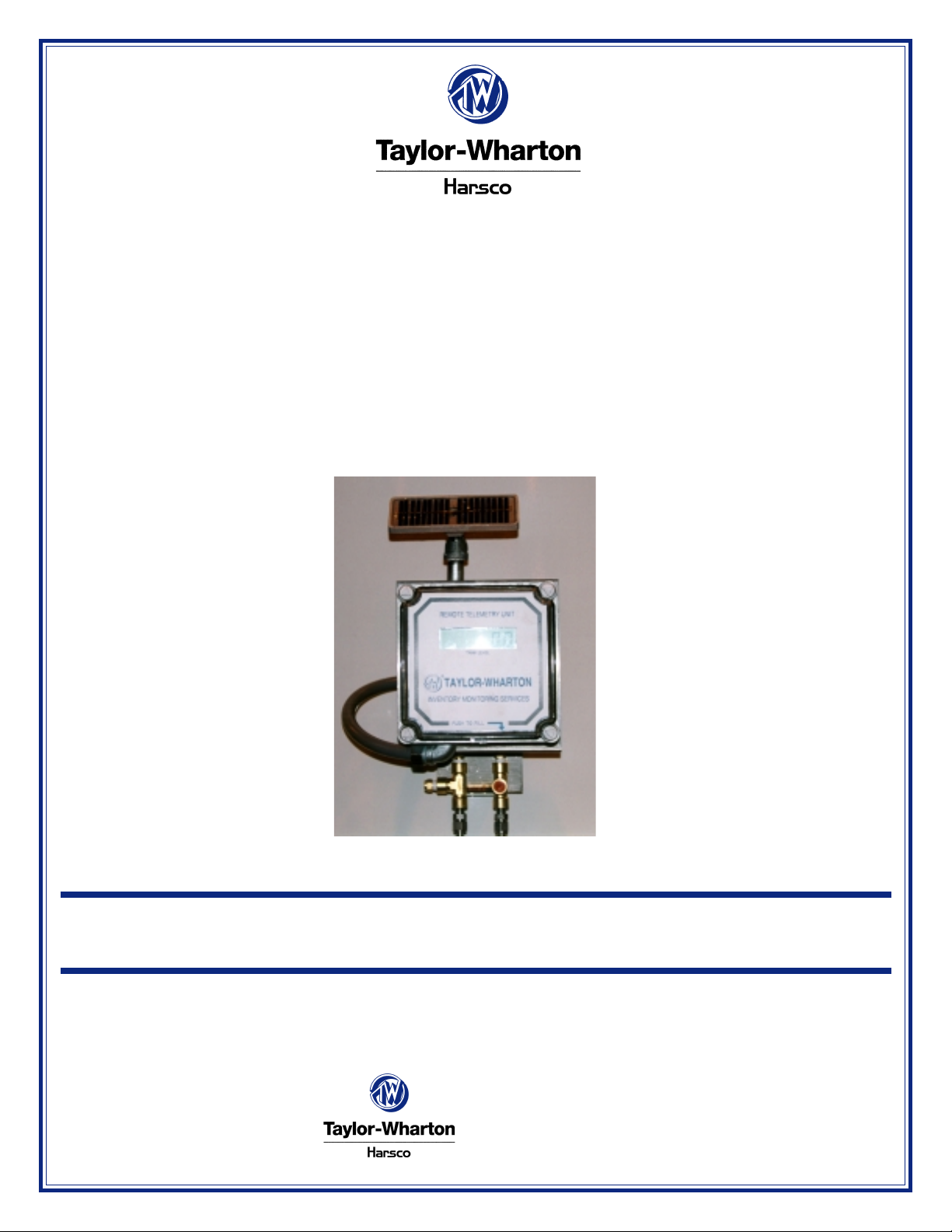
KeepFull Wireless/Internet Bulk Tank Liquid Level Monitoring System
PART NUMBERS 5740-8800 & 5740-8825
Do not attempt to use or maintain these units until you read and understand these instructions. Refer to Taylor -Wharton’ s
Safety First booklet (TW-202) for handling cryogenic material. Do not permit untrained persons to maintain this equip-
ment. If you do not understand these instructions, contact your supplier for additional information.
Taylor-Wharton
4075 Hamilton Blvd.
Theodore, AL 36582
Phone: (251) 443-8680
Fax: (251) 443-2250
BT-826
Page 2

Table of Contents
Table of Contents .................................................................................................. 2
Safety ..................................................................................................................3-4
Introduction .......................................................................................................... 5
Installation............................................................................................................. 6
System Activation ................................................................................................. 7
Web site.............................................................................................................7-10
A) Explanation of User Menus ............................................................... 10
B) Alarms.................................................................................................. 10
Part Numbers ...................................................................................................... 10
Troubleshooting .................................................................................................. 10
Warranty Service................................................................................................ 10
Bulk Vessel Registration Form.......................................................................... 11
Appendix A: Example of Bulk Vessel Registration Form.................................12
Appendix B: Example of Schedule 1 - Customer Information Form..............13
2
Page 3

The following safety precautions are for your protection. Before performing installation, operating, or maintenance procedures read and follow all safety precautions in this section and in reference publications. Failure to observe all safety precautions can result in property damage, personal injury, or possible death. It is
the responsibility of the purchasers of this equipment
to adequately warn the user of the precautions and safe
practices for the use of this equipment and cryogenic
fluids.
SAFETY PRECAUTIONS FOR LIQUID OXYGEN
Oxygen is a colorless, odorless, and tasteless gas that can
be condensed into a liquid at the low temperature of -297°F
(-183°C) under normal atmospheric pressure. Approximately
one-fifth of normal air is oxygen. As a liquid, oxygen is pale
blue in color. Oxygen is non-flammable but vigorously accelerates the burning of combustible materials.
Keep Combustibles Away from
Oxygen and Eliminate Ignition Sources
Many substances which do not normally burn in air require
only a slight spark or moderate heat to set them aflame in
the presence of concentrated oxygen. Other substances
which are only moderately combustible in air can burn violently when a high percentage of oxygen is present.
Do not permit smoking or open flame in any area where
liquid oxygen is stored, handled, or used. Keep all organic
materials and other flammable substances away from possible contact with liquid oxygen. Some of the materials that
can react violently with oxygen are oil, grease, kerosene,
cloth, wood, paint, tar , and dirt which contains oil or grease.
Under certain conditions flammable materials which have
become permeated with liquid oxygen are impact sensitive
and can detonate if subjected to shock.
Keep Area and Exterior Surfaces Clean
to Prevent Ignition
As normal industrial soot and dirt can constitute a combustion hazard, all equipment surfaces must be kept very clean.
Do not place oxygen equipment on asphalt surfaces, or allow grease or oil deposits to remain on benches or concrete
surfaces in the vicinity of the oxygen equipment. Use cleaning agents which will not leave organic deposits on the
cleaned surfaces. Equipment to be used in contact with
liquid oxygen should be handled only with clean gloves or
hands washed clean of oil.
Maintain Adequate Ventilation
Enclosed areas containing oxygen equipment should be ventilated to prevent accumulations of oxygen and thereby minimize combustion hazards.
Extreme Cold - Cover Eyes and Exposed Skin
Accidental contact of liquid oxygen or cold issuing gas with
the skin or eyes may cause a freezing injury similar to frostbite. Handle the liquid so that it won’t splash or spill. Protect
your eyes and cover the skin where the possibility of contact
with the liquid, cold pipes and cold equipment, or the cold
gas exists. Safety goggles or a face shield should be worn if
liquid ejection or splashing may occur or cold gas may issue
forcefully from equipment. Clean, insulated gloves that can
be easily removed and long sleeves are recommended for
arm protection. Cuffless trousers should be worn outside
boots or over the shoes to shed spilled liquid. If clothing
should be splashed with liquid oxygen or otherwise saturated
with the gas, air out the clothing immediately, removing it if
possible. Such clothing will be highly flammable and easily
ignited while the concentrated oxygen remains, and should
not be considered safe for at least 30 minutes.
Replacement Parts
Must be Suitable for Oxygen Service
Many materials, especially some non-metallic gaskets and
seals, constitute a combustion hazard when in oxygen service, although they may be acceptable for use with other cryogenic liquids. Make no substitutions for recommended spare
parts. Also, be sure all replacement parts are thoroughly
“Cleaned For Oxygen Service” in accordance with Compressed Gas Association (CGA) Pamphlet G-4.1 “Cleaning
for Oxygen Service” or equivalent industrial cleaning specifications.
Observe Safety Codes When
Locating Oxygen Equipment
Before locating oxygen equipment, become thoroughly familiar with National Fire Protection Association (NFP A) S tandard No. 50, “Bulk Oxygen Systems”, and with all federal,
state and local safety codes. The NFP A S tandard covers the
general principles recommended for the installation of bulk
oxygen systems on industrial and institutional consumer premises.
CAUTION: When installing field fabricated piping,
make certain a suitable safety valve is installed in each section of piping between
shut-off valves.
For more detailed information concerning safety precautions
and safe practices to be observed when handling cryogenic
liquids consult CGA pamphlet P-12 “Handling Cryogenic Liquids” available from the Compressed Gas Association, 1235
Jefferson Davis Highway , Arlington, Va. 22202.
3
Page 4

SAFETY PRECAUTIONS FOR LIQUID NITROGEN
Nitrogen is an inert, colorless, odorless, and tasteless gas
which makes up four-fifths of the air you breathe. Liquid nitrogen is obtained by cooling air until it becomes a liquid and
then removing the oxygen which makes up the other fifth of
the air. Liquid nitrogen is at a temperature of -320°F (-196°C)
under normal atmospheric pressure.
Extreme Cold - Cover Eyes and Exposed Skin
Accidental contact of liquid nitrogen or cold issuing gas with
the skin or eyes may cause a freezing injury similar to frostbite. Handle the liquid so that it won’t splash or spill. Protect
your eyes and cover the skin where the possibility of contact
with the liquid, cold pipes and cold equipment, or the cold
gas exists. Safety goggles or a face shield should be worn if
liquid ejection or splashing may occur or cold gas may issue
forcefully from equipment. Clean insulated gloves that can
be easily removed and long sleeves are recommended for
arm protection. Cuffless trousers should be worn outside
boots or over the shoes to shed spilled liquid.
Keep Equipment Area W ell Ventilated
Although nitrogen is non-toxic and non-flammable, it can
cause asphyxiation in a confined area without adequate ventilation. Any atmosphere which does not contain enough oxygen for breathing can cause dizziness, unconsciousness, or
even death. Nitrogen being colorless, odorless, and tasteless cannot be detected by the human senses and will be
inhaled normally as if it were air Without adequate ventilation, the expanding nitrogen will displace the normal air without warning that a non-life-supporting atmosphere is present.
Store liquid containers outdoors or in other well ventilated
areas.
Dispose of Waste Liquid Nitrogen Safely
Dispose of waste liquid nitrogen out-of-doors where its cold
temperature cannot damage floors or driveways and where
it will evaporate rapidly . An out door pit filled with clean sand
or gravel will evaporate liquid nitrogen safely and quickly .
CAUTION: When installing field fabricated piping,
make certain a suitable safety valve is
installed in each section of piping between shut-off valves.
For more detailed information concerning safety precautions and safe practices to be observed when
handling cryogenic liquids consult CGA pamphlet
P-12 “Handling Cryogenic Liquids” available from
the Compressed Gas Association, 1235 Jefferson
Davis Highway , Arlington, VA 22202.
NOTE: Argon is an inert gas whose physical prop-
erties are very similar to those of nitrogen.
For handling of liquid argon, follow the safe
practices described for the handling and
use of liquid nitrogen.
4
Page 5
Introduction
The bulk tank liquid level monitoring system provided by
Taylor Wharton provides the latest technology for local as
well as remote observation of a bulk tank’s contents. This
system enables an operator to check tank liquid level
from any computer that has Internet access as well as at
the tank site. With its local digital display it is a direct
replacement for the analog differential pressure “Contents Gauge” commonly being used. Because wireless
transmission is used and the unit is battery powered, no
external wiring is required. Therefore installation is as
easy as the replacement of the “Contents Gauge.”
The system consists of a differential pressure transmitter,
a local digital display , a cellular transmitter/receiver, and a
database service that is accessed through an Internet
Web site. Solar assisted batteries supply power for long
life. The differential pressure transmitter connects to the
same tank instrument lines as the “Contents Gauge.”
This component comes with 0-325” and 0-600” water
column spans. Every hour the pressure transmitter
senses the tank liquid level by measuring the differential
pressure produced by liquid in the tank. T ransmitter
output is communicated to the tank mounted telemetry
device in the form of a 4 to 20 mA electrical signal. The
hourly readings are locally stored and at least one time
per day they are all transmitted to the database. For local
observation of the current liquid level, a button is depressed causing a tank reading to be taken. The tank will
be sampled every 10 seconds for 15 minutes. During a
fill the same button is used and the tank will be sampled
at the same rate for 1 hour.
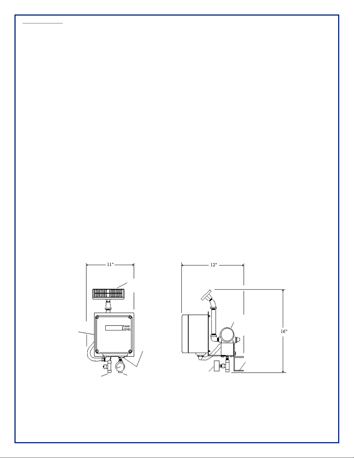
Figure 1 below shows the general layout of the telemetry
device.
Telemetry
Unit
High
Pressure
Tap
Solar
Panel
Button
For Local
Display
Low
Pressure
Tap
Figure 1: General Layout and dimensions
5
Tank
Pressure
Gauge
Differential
Pressure
Transmitter
Mounting
Bracket
Page 6

Installation
Before installing the telemetry unit inspect it carefully .
Report any damage to the carrier and Taylor Wharton
Customer Service. As shipped, the unit is operational and
ready to be installed on the tank. For installation on a
typical tank with an existing Contents Gauge follow these
steps.
1) Fill out the Bulk Vessel Registration Form supplied with
this manual and fax it to Taylor Wharton Customer
Service. This form, along with the Customer Information Form, filled out at the time of purchase is used to
prepare your Internet Web Site.
2) Verify that the dif ferential pressure transmitter sp an
(inches of water) covers the range required for the
tank.
3) Record the present liquid level and tank pressure as
indicated on the existing Contents Gauge Assembly.
Also, label the high and low-pressure instrument lines.
4) Close both instrument valves to isolate the existing
Contents Gauge Assembly from the t ank. Open the
Instrument Bypass valve to equalize the pressure
between the high-pressure and low-pressure side of
the Contents Gauge Assembly.
5) Carefully loosen the connections at the Contents
Gauge Assembly to relieve any pressure and then
remove the assembly .
6) Identify the high (H) and low-pressure (L) sides of the
Differential Pressure T ransmitter on the Telemetry Unit.
7) Mount the Telemetry Unit on the tank using the supplied bolts. See figure 2. The Telemetry Unit bracket
is designed to mate to a typical bracket supplied with
the tank. If there is a mismatch some field adaptation
may be required.
8) Solar panel must be directed to maximize southern sun
exposure. Turn the solar p anel by rot ating the 45°
elbow as much as one-quarter turn to direct the panel
to a maximized southern sun exposure. Caution, only
apply torque to 45° elbow using appropriate
wrenches.
9) Install an appropriate pressure gauge in the tee at the
low-pressure side of the telemetry unit. See figure 2.
10) Connect the instrument lines and then open the
instrument valves.
11) Leak test all connections using a suitable liquid leak
detector.
12) To obtain the current reading momentarily hold the “Fill
Button” until you see “FILL” on the display . The screen
will blink with the current reading. If “ERROR” is
displayed the high and low-pressure connections are
most likely reversed.
13) Activate your website.
Figure 2: T ypical Installation
Notes: All supplied pressure parts are
suitable and have been cleaned for
oxygen service. All field installed
parts must have a pressure rating
equal to or higher than the tank
MA WP, be suitable for oxygen service
and likewise cleaned. See the safety
precautions in the front of this
manual.
Seal all pipe threads using Teflon tape.
Telemetry
Unit
High
Pressure
Tap
Figure 2: Typical Installation
Low
Pressure
Tap
Solar Panel
45-degree Elbow
Existing Tank Bracket
Tank
Pressure
Gauge
Tube Adapter From
Instrument Tube Size
Connecting to 0.25” FNPT
Screw and Locknut
Supplied With Unit
4 Places
6
Page 7

System Activation
Y our Internet service provider is Dat aQwest Inc. Please
call their technical service group at (908) 464-2646 ext. 12
to commission your telemetry system. Units may be
commissioned Monday through Friday from 7:30 AM to
5:00 PM EST.
Y ou will be instructed to hold the “Fill Button” depressed
for about 20 seconds. “LOG ON” and then “CALL” should
appear on the display . The unit will log on to the network.
Expect this to take about 5 minutes. If “ERROR” is
displayed a failure to connect with the network is indicated.
In this event, please call DataQwest. Upon successful
transmission the Telemetry unit will receive its alarm points
and begin to log data. It is now on-line and ready to report
liquid level information.
Web site
After the telemetry unit is activated wait at least 3 business
days for the unit to collect and transmit the first readings
before accessing the DataQwest Web site for your tank.
You may access your telemetry Web site at http://
www.dataqwestinc.com. The following screen should
appear.
Click on “DATA ONLINE” at the left of the screen. A log on box like shown below will appear.
Type your Dat aQwest assigned user name and password and click “OK”. You should have received this information via telephone or letter from DA TAQWEST. If you have not received your user name and password, contact DATAQWEST’s Technical
Service Group at (908) 464-2646 ext. 12. A screen that shows a list of states where your telemetry equipped tanks are located
will appear.
7
Page 8

Click on the state to access a screen that will direct you to cities.
Clicking on the city of interest will produce a screen listing individual sites.
8
Page 9

Click on the site for a listing of tanks.
Clicking on the tank of interest will allow you to see its data.
9
Page 10

Explanation of User Menus
Alarms
At the bottom of this screen there are six choices for
viewing tank information and making changes to system
parameters. Click on each to view its features and
functions.
Change Request: This screen allows changes to tank
and sensor parameters. Upon receipt of a change request
“DataQwest” technicians will change the parameters.
Configuration: As shown above this screen gives
general tank and sensor information.
Events: Product deliveries and other important events are
displayed, with information about the time of their occur-
rence and the tank level afterwards.
Historical Data: Historical data showing product usage
and replenishment is display along with fill levels and
alarm points.
Site Summary: As shown above this screen list s the t anks
that are located at a particular site.
Site Directory: As shown above this screen lists the
St ates where tank sites are located.
When product level falls below a “critical point” the telemetry unit will within the hour transmit an alarm to the Web
site. A predetermined contact in your organization will
immediately be notified by E-mail or Fax.
Part Numbers
Two dif ferent telemetry units cover a dif ferential pressure
range from 0 to 600 inches of water. Order Taylor
Wharton’s part number 5740-8800 to receive a unit that
spans the range from 0 to 325 inches of water . For 0 to
600 inches of water order part number 5740-8825.
Trouble Shooting
If erratic or erroneous readings are indicated check all
pressure connections for leakage. Repair any leaks. If the
unit still is displaying false readings or no leaks are found,
call Taylor Wharton Customer Service.
Warranty and Service
For warranty and service call Taylor Wharton Customer
Service: 1-800-TW-TANKS.
10
Page 11

Bulk Vessel Registration Form
Please fax this completed form Attention: Taylor Wharton Technical Response Group (334) 443-2250 for each telemetry
device to be installed. This information should agree with that provided on “Schedule One: Customer Information form” that
was provided when your telemetry unit was ordered.
Contact for Website User Name and Password
Customer Name: Contact: Date:
Street: City: State: Zip:
Phone: Service Agreement Number:
T ank Site Information
Site Name: Installed by:
Streeet: City: State: ZIP:
Phone:
Please sketch the overall tank area, noting South and solar panel direction.
Building
Note any power sources:
Tank Information
Tank identification at tank site: (Serial # preferred) (Nominal size/model)
Product: Full Reading: (inches of H2O)
Reorder Reading: (inches of H2O) Low Level Alarm Reading (inches of H2O)
Please circle one:
Tank Orientation: Vertical or Horizontal Unit installed on: Tank or Instrument Stand
Original D.P. Gauge: Removed or Retained Are Extra Alarms to Customer Required? Yes or No
Tank liquid level and pressure prior to disconnection of existing gauges: Pressure: (psig)
Building
S
Note any obstructions:
Liquid level (inches)
T elemetry Device Information
Device I.D. Sensor span:
Comments:
11
Page 12

Appendix A: Example of Bulk Vessel Registration Form
Bulk Vessel Registration Form
Please fax this completed form Attention: Taylor Wharton Technical Response Group (334) 443-2250 for each telemetry
device to be installed. This information should agree with that provided on “Schedule One: Customer Information form” that
was provided when your telemetry unit was ordered.
Contact for Website User Name and Password
Customer Name: Contact: Date:
Street: City: State: Zip:
Phone: Service Agreement Number:
(000) 000-0000
JL Welding Company Jane Doe
123 Any Street XX 00000
Someville
TWRB-123
T ank Site Information
Site Name: Installed by:
Streeet: City: State: Zip:
Phone:
Ace Metal Works Inc.
78 Ginger Rd.
(000) 000-0000
Someville
Please sketch the overall tank area, noting South and solar panel direction.
Note any power sources:
Note any obstructions:
Jack Doe
Building
XX
S
00/00/00
00000
Building
Tank Information
Tank identification at tank site: (Serial # preferred) (Nominal size/model)
Product: Full Reading: (inches of H2O)
Reorder Reading: (inches of H2O) Low Level Alarm Reading (inches of H2O)
Please circle one:
Tank Orientation: Vertical or Horizontal Unit installed on: Tank or Instrument Stand
Original D.P. Gauge: Removed or Retained Are Extra Alarms to Customer Required? Yes or No
T elemetry Device Information
Device I.D. Sensor span:
Comments
Nitrogen
100
S/N-XXXX
311
FGD123P4 0-400
12
VT-6,000-250
85
108
152
Page 13

Appendix B: Example of Schedule 1- Customer Information Form
Schedule 1: Customer Information Form
Customer Billing & Notice Information for Monthly Web Service
Customer Name: Contact:
Street: City: State: Zip: Phone:
Service Agreement Number: Effective Date:
Fees
Monthly Fee: $ 1x Activation Fee: $
T ank Site Information
Site Name: Contact (if any):
Street: City: State: Zip: Phone:
Transmission Coverage Checked: Y or N Transmission Frequency: Every 12/24/ hrs.
T ank Information
123 West Street
7878 Ginger Road
ABC Gas Distributor
ACE Metal Works Inc.
John Williams
Someville
TWRB-123 00/00/00
Someville
XX 00000 (000) 000-0000
Jack Doe
XX
00000
(000) 000-0000
Tank Identification at Tank Site (Serial Number if possible):
Nominal Size & Model: Product:
Full Reading: (inches of H20)
Reorder Reading: (inches of H20)
Low Level Alarm Reading: (inches of H20)
Please Circle One:
Tank Orientation: Vertical or Horizontal Unit installed on: Tank or Instrument St and
Are Extra Alarms to Customer Required: Y or N Original D.P. Gauge: Removed or Retained
Contact for Web Site User name and Passwork
Customer Name: Contact:
Street: City: State: Zip: Phone:
Current DataQwest Web Site Username (if any):
77 Hickory Lane Someville XX 00000
VT-6,000-250
311
100
85
JL Welding Company
S/N-XXXX
Nitrogen
Jane Doe
(000) 000-0000
JLWelding
Alarm Method: Email Address:
Fax Number:
Name of Contact:
JLWelding@JLWelding.com
(000) 000-0000
Jack Smith
13
Page 14

Taylor-Wharton
4075 Hamilton Blvd.
Theodore, AL 36582
Phone: (334) 443-8680
Fax: (334) 443-2250
www.taylorwharton.com
Part # 99187826 © 2001 Harsco Corporation BT-826
 Loading...