

Page 1
easyCarb™ Manual
TW-339
Keep Equipment area Well Ventilated. Carbon Dioxide can cause asphyxiation by
displacing oxygen needed for breathing, resulting in dizziness, unconsciousness, or
death. Carbon dioxide cannot be detected by the human senses and will be inhaled
like air. If adequate ventilation is not provided, the gas may displace normal air
without warning that a life-threatening atmosphere is developing. Store and use
carbon dioxide containers only in well ventilated areas.
Page 2

Page 3

Extreme cold can Injure Eyes and Skin. If released to atmosphere, liquid carbon
dioxide will turn to carbon dioxide snow or dry ice. Accidental contact of carbon
dioxide snow or cold gas with the skin or eyes may cause severe frostbite. If you are
accidentally exposed to cold snow or gas, consult a physician at once. Warm affected areas with water that is near body temperature as a first aid measure.
For additional information on carbon dioxide, ask your supplier for a Material
Safety Data Sheet on this gas. Material Safety Data Sheets contain complete
hazard and first aid information for the product they cover. For more information on the principles of operation and safe practices for carbon dioxide
equipment refer to the Compressed Gas Association publication G-6 available from the Compressed Gas Association Inc. 1235 Jefferson Davis
Highway, Arlington, VA 22202.
3
CARBON
DIOXIDE
SAFETY
PRECAUTIONS
FREIGHT DAMAGE CLAIMS ARE YOUR RESPONSIBILITY. Liquid containers
are delivered to your carrier from Taylor-Wharton’s dock in new condition.
When you receive our product you may expect it to be in that same condition.
For your own protection, take time to visually inspect each shipment in the
presence of the carrier’s agent before you accept delivery. If any damage is
observed, make an appropriate notation on the freight bill. Then, ask the driver
to sign the notation before you receive the equipment. You should decline to
accept containers that show damage, which might affect serviceability.
The easycarb™ system consists of a vacuum-insulated liquefied gas container, and
its associated plumbing. The system is designed for permanent installation as a
source of gaseous carbon dioxide for soft drink carbonation. The easycarb™ unit is
manufactured to the ASME pressure vessel code.
The easycarb™ container is filled from an outside fill station without interrupting the
flow of gaseous carbon dioxide to the points of use. Two lines are permanently
attached between the easycarb™ and a lockable fill box outside the building. One
line is used to transfer liquid to the system from a distribution vehicle, the other
conducts gas vented by safety devices to the outside of the building. The fill box
station must be located for easy access by the distribution vehicle. Filling is accomplished by connecting a delivery unit to the fill port in this box. Liquid CO
transferred by pressure differential.
is then
2
FREIGHT
DAMAGE
PRECAUTIONS
GENERAL
INFORMATION
The easycarb™ operates without the need for constant attention. Personnel working
at the use site may need to call their distributor to make occasional output pressure
regulator adjustments, but the other valves and controls on top of the container are
normally operated only when it is necessary to turn off the gas flow for maintenance,
or if the system is damaged by mishap.
Page 4
4
g
(
g)
.
)
)
)
An automatic pressure building system makes the easycarb™ a self contained gas
supply system capable of providing gas at maximum continuous flow rates of up to
10.0 lb./hr. (4.5 kg/hr.) See Specification Chart below for desired EC Model.
The easycarb™ is designed to supply gas from the pressurized space that is above
the liquid inside the container. If high-demand applications cause the pressure in this
space to drop below 125 psig (8.6 bar/862kPa), the pressure building regulator opens
to maintain the gas pressure level. The container will hold liquid with no loss as long
as a product is used at a rate listed in the Specification Chart below.
The gas supply line is equipped with a check valve to prevent back flow into the
easycarb™. Back flow could carry contaminants that could freeze in the cold plumbing parts, making the easycarb™ inoperative.
Solid CO
70 psig (4.8bar/483 kPa). In service, the pressure is maintained well above this value
to ensure that solid CO2 (dry ice) will not form inside the container.
easycarb™ Specifications
Model EC-150EC-300EC-450EC-600
Part Number
Dimensions
Diameter in. (mm) 20 (508) 20 (508) 20 (508) 22 (559)
Height in. (mm) 34.7 (881) 49.4 (1255) 64.6 (1641) 70.0 (1778)
Weight, Empty lb. (kg) 140 (64) 200(91) 260 (118) 355 (161)
, CO
Capacity
Liquid lb. ( kg) 161 (73) 301 (137) 447 (203) 594 (269)
Gaseous cu. ft. (cu. m) @ NTP (STP) 1403 (37) 2628 (69) 3906 (103) 5195 (136)
Flow Rates
Peak Demand lb./hr. (kg/hr) 4.5 (2.0) 7 .0 (3 .2) 12.0 (5.4) 20.0 (9.0)
Continuous lb./hr. (kg/hr) 3.0 (1.4) 5.0 (2.3) 7.0 (3 .2) 10.0 (4.5)
Minimum Usa
Liquid lb. /day (kg/day) 1. 8 (.82) 2.5 (1.13) 2.7 (1. 22) 2.9 (1.32)
Pressure Building System
Standard Operating Pressure
Safety Device Settings
Inner Container Prim ar y Relief Valve
Inner Container Safety Head
Electrical Requirements**
Heater Vol tage
Heater Current
Saturated @ 125 psig (8.6 bar)
2
No Ventin
e
(dry ice) will form if the pressure in the easycarb™ is allowed to drop below
2
EC15-0C00 EC30-0C00 EC45-0C00 EC60-0C00
125 psig (8.6 bar
300 psig (20.7 bar
450 psig (31.0 bar
* Flow rate using 240 VAC power. Using 208 VAC power, flow rate is 40 lb./hr. (18.1 kg/hr) peak and 30 lb./hr. (13.6 kg/hr) continuous
INSTALLATION
INSTRUCTIONS
Taylor Wharton’s easycarb™ carbon dioxide system is designed to be permanently
installed. The system consists of a specifically designed container that stores carbon
dioxide in the liquid state, and fill connection hardware to allow refilling from outside
the building in which it is installed.
Page 5
Planning the Installation
g
g
g
Consult with your customer, and check local code restrictions, before determining a
location for the unit. The container should be installed in a location away from day to
day activity to minimize tampering. It should be accessible for maintenance and
occasional monitoring.
The fill box should be readily accessible for CO2 deliveries 24 hours a day. A lockable fill box is part of the installation. The fill box location should be within 35-ft.
(10.7m) of the delivery point, due to the limited reach of the delivery vehicle.
For safety and ASME code requirements, the length of the fill line and vent lines from
the fill box to the easycarb™ must not exceed 20-ft. (6m) in length. Consult TaylorWharton for technical assistance when installing longer lines to avoid problems.
A stainless steel surface mounted fill box is most commonly used as it minimizes
modifications to the building and installation time. However, flush mounted fill boxes
are available.
5
Note:
This container is manufactured
to ASME pressure vessel
specifications. It should not be
used to transport liquid carbon
dioxide. The easycarb™ is
intended to be transported to
the installation site empty and
filled after it is installed.
Plan the routing of fill and vent lines. These should be in an area well protected from
accidental damage. If you can’t conceal the lines, mount them to the interior walls, or
secure them to overhead structural members as required by many local codes. Avoid
hot areas if possible.
Do not route easycarb™ lines near steam or hot water lines. For local regulations
that require the cylinder to be elevated from the floor, we offer a platform base. If the
platform base is used to elevate the cylinder; the cylinder must be anchored to a wall
by its handling ring. Part numbers of the platform base and wall anchor can be found
in the Replacement Parts List. It is recommended that appropriate local code approvals be reviewed prior to scheduling the installation.
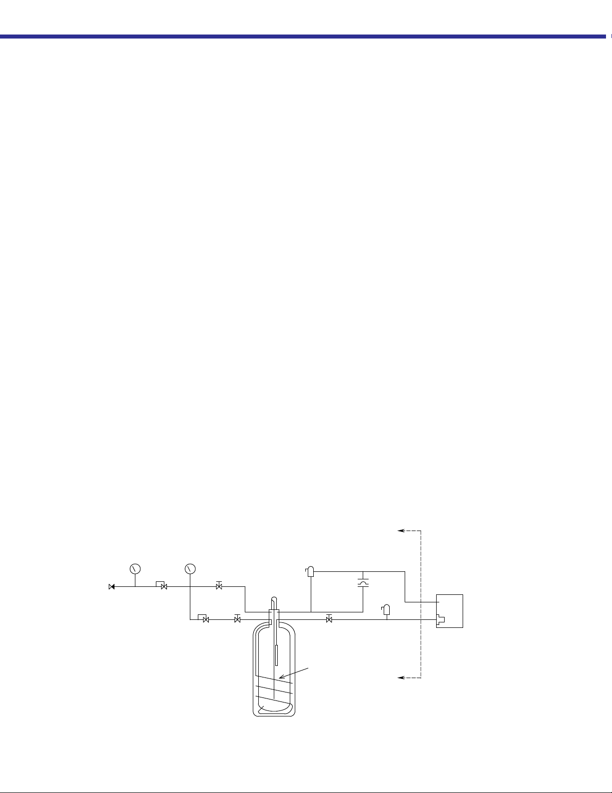
easy
Supply to Drink
Machine
CARB
Flow Diagram
Supply Line
Pressure Gau
Check Valve
e
Gas Use
ulator
Re
Container
Pressure
Gauge
Regulator
Pressure
Building
Isolation
Valve
Isolation
Valve
Liquid Cont ents
Gau
e
Inner Container
Relief Valve
Fill Valve
Inner Contai ner
Safety He a d
Relief Valve
Fill Line
Vent
Fill
Fill
Station
Pressure
Building Coil
Standard
Components
included on all
easyCARB
products
Page 6
6
CAUTION:
If lifting by crane or hoist,
insert hooks in
openings on the cylinder ring.
Failure to do so could result
in container damage or
personal injury.
CAUTION:
If the container is installed in an
elevated location, it must be on
a well constructed platform that
will support more than 975 lb.
(422 kg.) When installed this
way, the easycarb™ must be
anchored to the wall from a
point on the top of the
container.
both lifting lug
Cylinder Handling
The easycarb™ cylinder can weigh upwards of 375 lb. (170 kg), but can easily be
moved by using a properly designed hand truck. A special Harper cylinder truck
(Model ULG 650A) is recommended. The container can also be lifted and moved
with a crane or hoist by attaching a sling to the holes, provided in the ring supports on
the top of the cylinder. Do not attach lift hooks to ring. Except for minor tipping on
the hand truck, the container must be kept upright at all times, and should not be
moved or transported full.
Installation Procedure
See page 12 for Component Identification.
1. Determine the location for the fill box on the outside wall.
SPECIAL NOTICE
Be sure and take the height of the fill box into consideration. Do not install box at
face height (approx.5 ½ ft./1.7 m). This can be dangerous during delivery. The
suggested height of mounting is approx. 3 to 4 ft. (.9 to 1.2m) above the ground.
WARNING:
Be sure there are no hidden utility lines in the location selected for mounting.
Consult the building plans, or make a test opening to confirm the wall is clear
of hidden hazards before drilling.
Note:
Nut and ferrule for vent line
and liquid connection are
attached to the plumbing to
prevent loss during shipment.
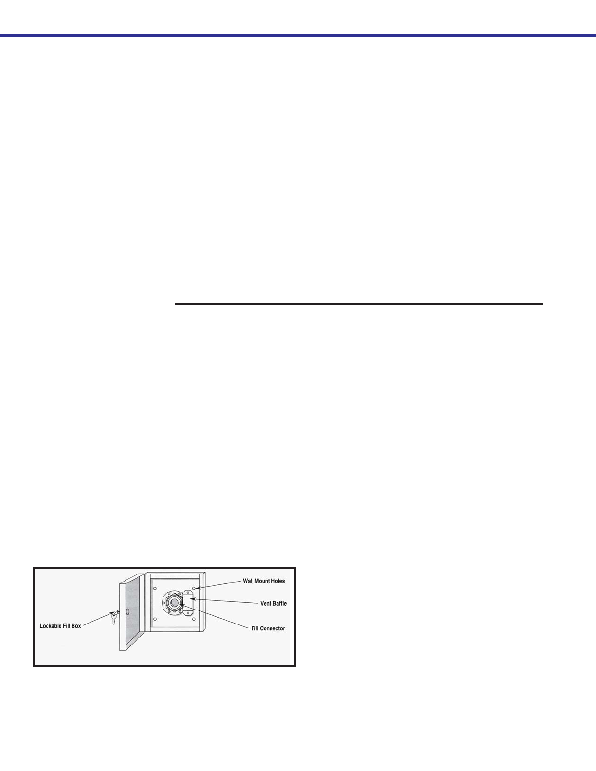
Fill Station
2. Measure the distance from the container to location where the fill box will be mounted to
determine the length of fill and vent line material required. Be careful to allow for all
routing and for thickness of the outside wall. Avoid sharp bends that may restrict liquid or
gas flow.
3. Fabricate two lengths of ½ in. (12.7 mm) ODT copper or ½ in. (12.7 mm) I. D. nylon
tubing.
4. Drill a small pilot hole through the outer wall surface first to confirm that there are
no utility lines in the location selected, then enlarge the opening to a 2 ½ in. (64
mm) opening.
5. The fill box contains copper tube sections long enough to pass through the wall.
The fill section is already coupled but you must attach the vent section to the
bracket beneath the fill coupling using the strap clamp
and screws provided.
6. Pass the fill line through the wall, and mark for
cutting to length. Pull the fill box back off the wall. Cut
fill line to length, then cut vent line to same length, and
secure with screw to bracket in back of fill box.
7. After cutting the fill box tube sections to length,
install the box. Level the box, then mark four wall
anchor holes and drill; secure with appropriate anchoring hardware. Weather seal between the box and the
building exterior is recommended.
Page 7

7
8. Attach the two 90o elbow compression unions to the tubing ends coming through
the wall and direct them toward the fill/vent lines.
9. Carefully unload the easycarb™ tank and move it to its permanent position. It is
recommended that you securely anchor the top of the container to the wall or building
structure with a suitable bracket that clamps the top handling ring.
WARNING:
Be careful to properly connect the vent and fill lines to the box. If the vent line
is accidentally connected to the fill connection, the container relief device may
be blocked, which will create a dangerous pressure build-up in the lines or the
container
.
10. Route and mount both lines using ½ in. (12.7 mm) O.D. lines inside the building ,
until they reach the easycarb™ tank. Be sure to comply with all local building
codes.
11. Cut the vent line to final length and connect it to the elbow fitting on the vent tube
leading to the outside box.
12. Go to the container end of the vent line and test the line before attaching to the
container by blowing through the line to confirm that is unrestricted.
13. Cut fill line to final length, couple it to the remaining fill box elbow, then connect it
to the LIQUID connection on the easycarb™.
Note:
Liquid connection fitting must
be assembled to liquid line
using pipe thread sealant,
such as teflon tape, prior to
attaching the liquid line
connection.
Note:
After completing the tank
installation, fill out the
easycarb™ Warranty Card
and return to Taylor-Wharton.
14. Apply the easycarb™ decal to the front of the container and post carbon dioxide
storage identification in the general area as required by local code.
Leak Checking the Installation
Open the LIQUID valve and close the USE and PB valves. Pressurize the system to
150 psig (10 bar/1034 kPa) with gaseous CO2 through the fill connection. Leak test
all joints using only approved leak test solutions. Follow the manufacturer’s recommendations. Snoop Liquid Leak Detector is one approved solution; it is available
from: Nupro Co. 4800 E. 345th St. Willoughby, Ohio 44094. Leak test all connections.
If leaks are found, isolate the leaking plumbing from the tank pressure so all pressure
may be released from the area under repair.
WARNING:
In case of any downstream leaks to the point of use, close the USE Valve and
the PB Valve. Closing these valves will stop the flow of gaseous CO2 to the
Supply Line Regulator and downstream piping so that repairs can be made to
any leaks.
Supply Line Installation
1. Fill the easycarb™ using the filling procedure on page 7.
2. Install a gas supply line from the Supply Line connector, on the easycarb™ to the
use point and finger tighten.
Page 8

8
FILLING
THE CONTAINER
Note:
During first fill the easycarb™
will be warm and pressure may
equalize before tank is full. If
this occurs, shut off liquid on
fill gun and vent pressure in
easycarb™ down to 125 psig
(8.6 bar/862 kPa) through fill
gun. Repeat if necessary. If
you are not sure if the
easycarb™ is full simply
check liquid contents gauge on
the easycarb™ before venting.
3. Open the gas USE valve and adjust the outlet regulator – normally to 90 psig (6.2
bar/621 kPa).
4. Tighten the supply line fittings at the use point.
Schedule delivery before the container contents drop below ¼ full. This will improve
the filling characteristics as well as the gas withdrawal capabilities.
1. Inspect the easycarb™ for proper vent, supply and fill line installation before
attempting to fill the container.
2. Check supply container valves to ensure they are open.
3. Check the pressure and contents of the supply container(s).
4. Extend the fill hose to the fill box.
5. Inspect all connections for cleanliness. Any moisture that is present can freeze
during liquid transfer. Use a clean, dry cloth to wipe connections if necessary.
6. Open liquid ball valve and purge the fill gun vent until liquid appears. After this is
complete shut the liquid ball valve. Next shut the vent ball valve.
7. Connect the fill gun to the fill connector and read the customer tank pressure to
ensure a positive differential.
MAINTENANCE
CAUTION:
Carbon dioxide may form into
the solid phase (dry ice) if the
pressure over the liquid is
allowed to drop below 70 psig
(4.8 bar/483 kPa). Pressure in
the container must be
maintained above this value to
ensure solid CO2 will not form
inside the container. Before
performing maintenance, the
contents of the easycarb™
must be transferred to another
container so that pressure can
be released.
8. Open the liquid valve on the fill gun to begin the fill. Never leave the Fill Gun
unattended during the fill.
9. When the pressure indicated on the fill gun begins to rise sharply, terminate the
fill.
10. Close the Liquid Fill valve, and disconnect the fill gun from the fill station. Open
the fill gun Vent valve to relieve trapped pressure
.
WARNING:
Delivery systems with operating pressures greater than 300 psig (20.7bar/2068
kPa) may over-pressurize the easycarb™ if not used properly. Do not allow the
pressure, as displayed on the fill gun, to exceed 300 PSI during the fill.
For specific maintenance procedures refer to the applicable paragraph that follows,
and to the replacement parts list.
WARNING:
Isolate components and slowly de-pressurize the plumbing to be repaired
before attempting repairs. The sudden release of pressure could cause personal injury. Observe safety precautions to prevent dangerous accumulation of
gas. Safety devices and liquid level contents gauge cannot be isolated, therefore all liquid must be removed and all pressure in vessel must be relieved
before attempting to repair them.
Page 9

9
Parts Cleaning
Before installing, be sure to properly clean any replacement parts that are not packaged and marked for oxygen service. Keep all parts clean during installation to
prevent contamination of the carbon dioxide. For more information on cleaning,
consult the compressed Gas Association (CGA) pamphlet G-4.1, “Cleaning for
Oxygen Service” or equivalent industrial cleaning specifications.
Leak Testing
After every repair, pressurize the container to about 280 psig (19.3 bar/1931 kPa) through the
Liquid connection with a regulated source of clean dry carbon dioxide gas. Use only approved leak test solutions and follow the manufacturer’s recommendations. “Snoop” Liquid
Leak Detector is one approved solution, it is available from: Nupro Co. 4800 E. 345th St.
Willoughby, Ohio 44094. If leaks are detected, isolate container pressure and relieve pressure
on the lines before repairing, then retest when repairs are completed.
Relief Valves
Replace the relief valve when it fails to maintain its setting or when it leaks at pressures below
its setting. If the relief valve functions properly, but operates too frequently, it may be an
indication that the insulation space vacuum has deteriorated. Follow the instructions in the
Evaporation Rate Test Procedure to check the condition of the vacuum. Never try to repair
relief valves.
Inner Container Safety Head
1
CAUTION:
If the contents have solidified,
the dry ice in the container
may be thawed by
pressurizing the container to
280 psig (19.3 bar/1931 kPa)
with carbon dioxide gas from
an external source. This may
be accomplished by
connecting a high pressure
cylinder with regulator to the fill
line of the easycarb™
(adapters will be required).
Several days at this pressure
may be required to thaw the
container. For more
information, consult CGA
pamphlet G-6.7, “Safe
Handling of Liquid Carbon
Dioxide Containers that have
Lost Pressure.”
If the inner container safety head (frangible disc) ruptures, determine and correct the
cause of the rupture before replacing the safety head assembly. Then leak test the
plumbing in accordance with the Leak Test instructions.
Supply Line Regulator
The supply line regulator reduces the pressure of the carbon dioxide gas from the
easycarb™ container to the level required by the carbonation system. It provides a
constant supply pressure. To adjust the supply line regulator:
1. Loosen the adjustment screw retaining nut.
2. Adjust the regulator (tee handle) on the Supply Line Pressure Gauge.
3. Tighten the adjustment screw retaining nut.
Pressure Building Regulator
If the regulator fails to close properly, and allows container pressure to rise above the
125 psig (8.6 bar/862 kPa) setpoint, replace the regulator.
After replacement, or if the pressure building circuit is maintaining a pressure minimum other than 125 psig (8.6 bar/862 kPa), the regulator may be adjusted using the
following Field Adjustment Procedure. For more precise adjustment, remove the
regulator and use the Bench Adjustment Procedure.
1
See warning on removing contents before releasing container pressure at the beginning of the Mainte-
nance Section.
Page 10
10
Note:
Pressure in the container must
be above the desired pressure
building setting.
Note:
One-half turn of the adjusting
screw will raise or lower the
setpoint approximately 35 psig
(2.4 bar/241 kPa).
CAUTION:
Internal orifices in pressure
regulators used with CO2 are
subject to the formation of dry
ice if excessively cold gas or
extremely high flow rates are
used. If this condition occurs,
it is usually an indication of a
leak in the equipment or
plumbing downstream of the
easycarb™ system. Check for
leaks and make repairs as
necessary. If no leak is found,
and ice formation continues,
your application may require
increasing system output by
installing an external vaporizer
or second easycarb™ unit.
Field Adjustment Procedure
. For adjustment on the container:
1. Close pressure building isolation valve and use valve.
2. Relieve pressure in the pressure building loop by opening the compression fitting
near the pressure building regulator.
3. Re-tighten fitting opened in step 2.
4. Loosen the lock-nut and turn (counter-clockwise) the adjusting screw on the
pressure building regulator all the way out.
5. Open the upstream pressure building isolation valve.
6. Turn the adjusting screw clockwise until the container pressure reads: 125 psig
(8.6 bar/862 kPa).
7. Tighten the lock-nut on the regulator adjustment.
8. Open the use valve.
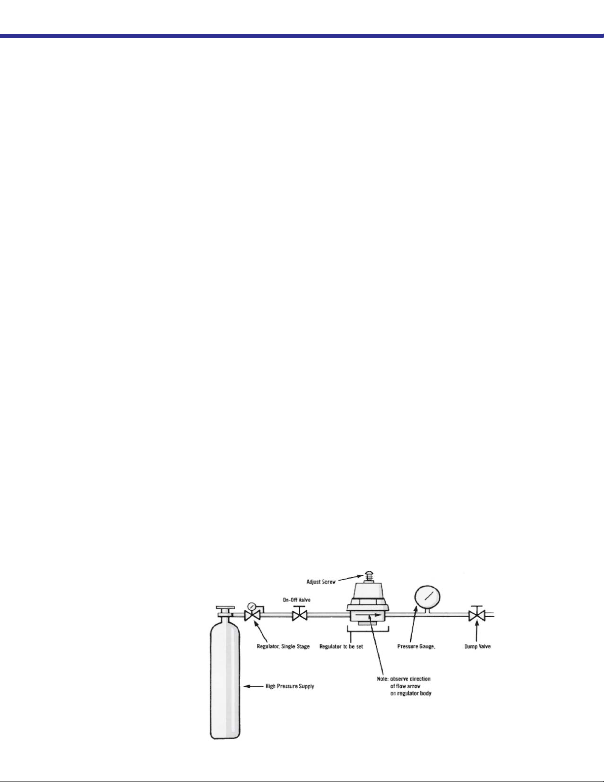
Pressure Building Regulator Bench Adjustment Procedure. Assemble the
pressure building regulator adjustment fixture, and regulator to be adjusted, as shown
in the accompanying illustration.
1. Close the On/off valve, and the Dump valve.
2. Set the high pressure regulator above the desired setpoint for the Pressure
Building regulator.
3. Crack and open the high pressure cylinder valve.
4. Slowly open the On/ off valve and observe the pressure gauge.
5. When the regulator under test opens, the setpoint may be read on the Pressure
Gauge.
Regulator Bench
Adjustment Fixture
6. Close the On/off valve, and open the Dump valve.
7. To reset the regulator, loosen the lock-nut on the adjusting screw. Raise pressure
by turning the adjusting screw clockwise; lower pressure by turning the screw
counter-clockwise. After adjustment, repeat steps 4 and 5 to check the setting
before reinstalling the regulator on the easycarb™.
Page 11
11
Checking Container Performance
The easycarb™ is basically two containers, one within the other. The space between
the containers acts as a thermal barrier because of high technology insulation and a
vacuum. Each serves a very important part in the useful life of the container. The
insulation is very effective in preventing radiated heat from entering the inner container; the vacuum prevents heat convection or conduction from reaching the liquid
contents. When the vacuum in the insulation space is no longer effective, the following symptoms may appear:
· When the container is filled with liquid, the outer casing will be much colder than
normal.
· Frost, indicating the liquid level, may be visible on the outer casing of the container.
· The container may appear to "sweat" if the air surrounding the container is hot and
humid.
· The relief valve will open continuously until the container empties prematurely.
Normal Evaporation Rate (NER) Testing. If a loss of vacuum integrity is suspected,
the container's Normal Evaporation Rate should be checked. However, always
perform a visual check of the inner container safety head before proceeding with the
test. If the safety head is ruptured, it must be replaced before performing the test. If
the safety head is intact, take the container out of service and perform the following
test:
The pressure building valve must be closed during the NER test. The container must
be in a well ventilated area where the temperature is approximately 70°F (21°C.)
Note:
See the TROUBLESHOOTING Section for more
detailed symptoms.
1. Fill the container until it contains at least 100lb. (45 kg) of liquid for the EC400 and
125 lb. (57 kg) for the EC600.
2. Allow the container to stabilize with all valves closed until it vents through the relief
valve. Weigh the container. Record the weight, time, and date.
3. Reweigh after the container is allowed to vent for 24 hours. Record the weight,
time, and date.
4. If the weight of the carbon dioxide lost in 24 hours is greater than 8lb. (3.6 kg), the
container may have lost its vacuum.
5. If the above test is inconclusive, reweigh again after 48 hours.
The test is most affective if container is not moved during this period.
6. If the total amount of carbon dioxide lost in the 48 hour test
exceeds 17 lb. (7.7 kg), the container may be considered defective.
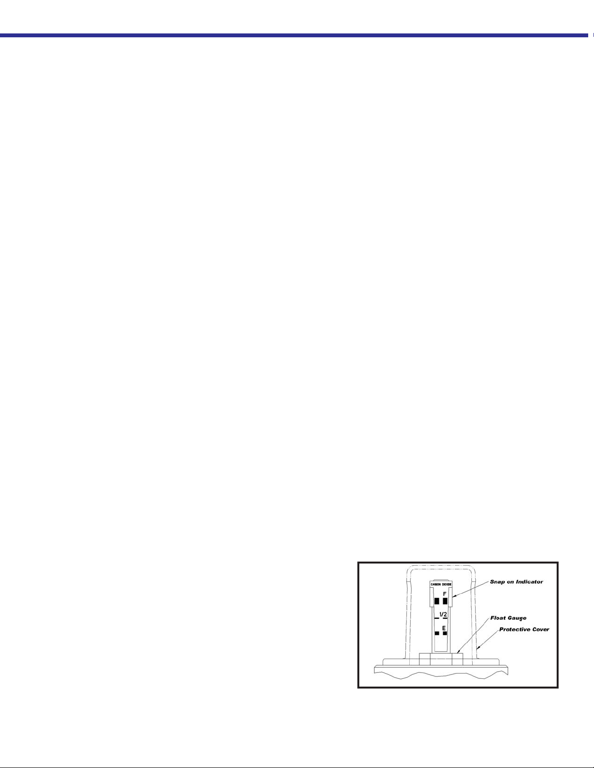
Full View Contents Gauge
The content of these containers is measured with the Full View
Contents Gauge. The device consists of the gauge body and snap
on level indicator. When the gauge is assembled, the indicator is
magnetically coupled to the top of a float rod that moves up or down
with the changing level of liquid in the container.
Page 12

12
CAUTION:
When installing the gauge
assembly, care must be taken
to ensure that the float rod is
inserted through the “guide
ring” located on the fill line
inside the container. If the
gauge does not engage this
ring, the contents indication
will be inaccurate, or the
gauge may be damaged in
use.
Replacing the Full View Contents Gauge
The easycarb™ must be empty of liquid carbon dioxide before attempting to remove
the contents gauge, or the contents will solidify. Remove all pressure from container
and remove the clear protective cover by removing three (3) screws at its base.
Unscrew gauge body using a wrench on the hex fitting at the base of indicator tube.
Lift the entire gauge assembly free of the container. The gauge assembly is long and
may be very cold. Gloves should be used to protect your skin.
Contents Gauge Installation.
Before installing a new or repaired gauge, inspect the gasket, if any damage is
apparent replace.
1. When inserting the gauge assembly, lower the float rod through the gauge
opening until about 8 in. (203 mm) of the float rod remains above the container.
2. Grasp the upper portion of the float rod with two fingers so that the assembly
hangs free and “plumb”.
3. Lower the assembly about 4 in. (102 mm) slowly and try to keep the rod in the
center of the threaded entrance hole as you do. If you are careful during this
portion of insertion, you will drop the float rod straight through the guide ring
inside the container.
4. To confirm that the rod is correctly positioned in the container, stop where you
can still grasp the top of the rod and try to swing the lower end from side to side.
5. When the rod is engaged in the guide ring, the rod will be restricted to lower end
movement of about ½ in. (12.7 mm); if you can feel greater movement, withdraw
the rod to the point where its top is 8 in. (203 mm) above the gauge opening and
try again.
6. When you are satisfied that the gauge rod is correctly installed, lower the assembly the rest of the way into the container until the top portion threads can be
engaged.
7. Screw the gauge in place and hand torque to about 20 ft. lbf (2.8 kgf m). Leak
check the connection of gauge body to the flange, and replace the protective
cover.
Page 13
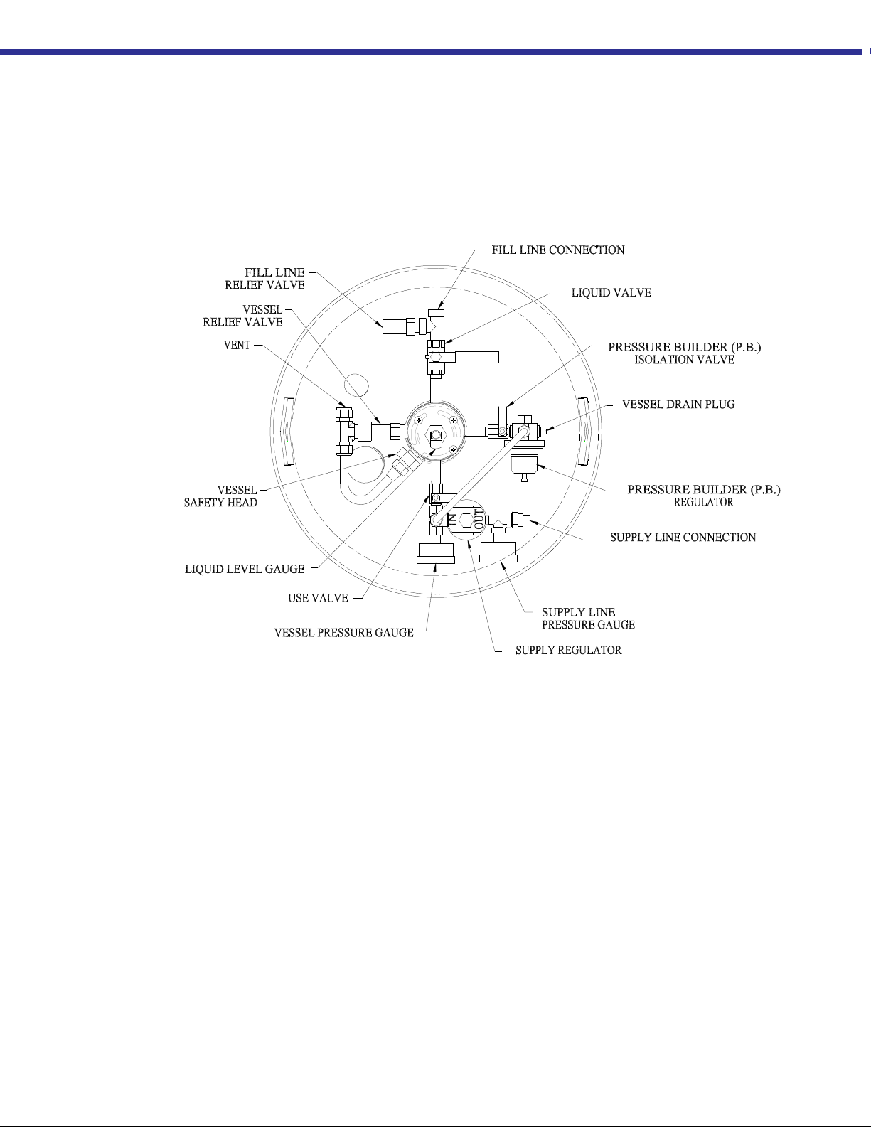
13
COMPONENT I.D.
Page 14

14
p
p
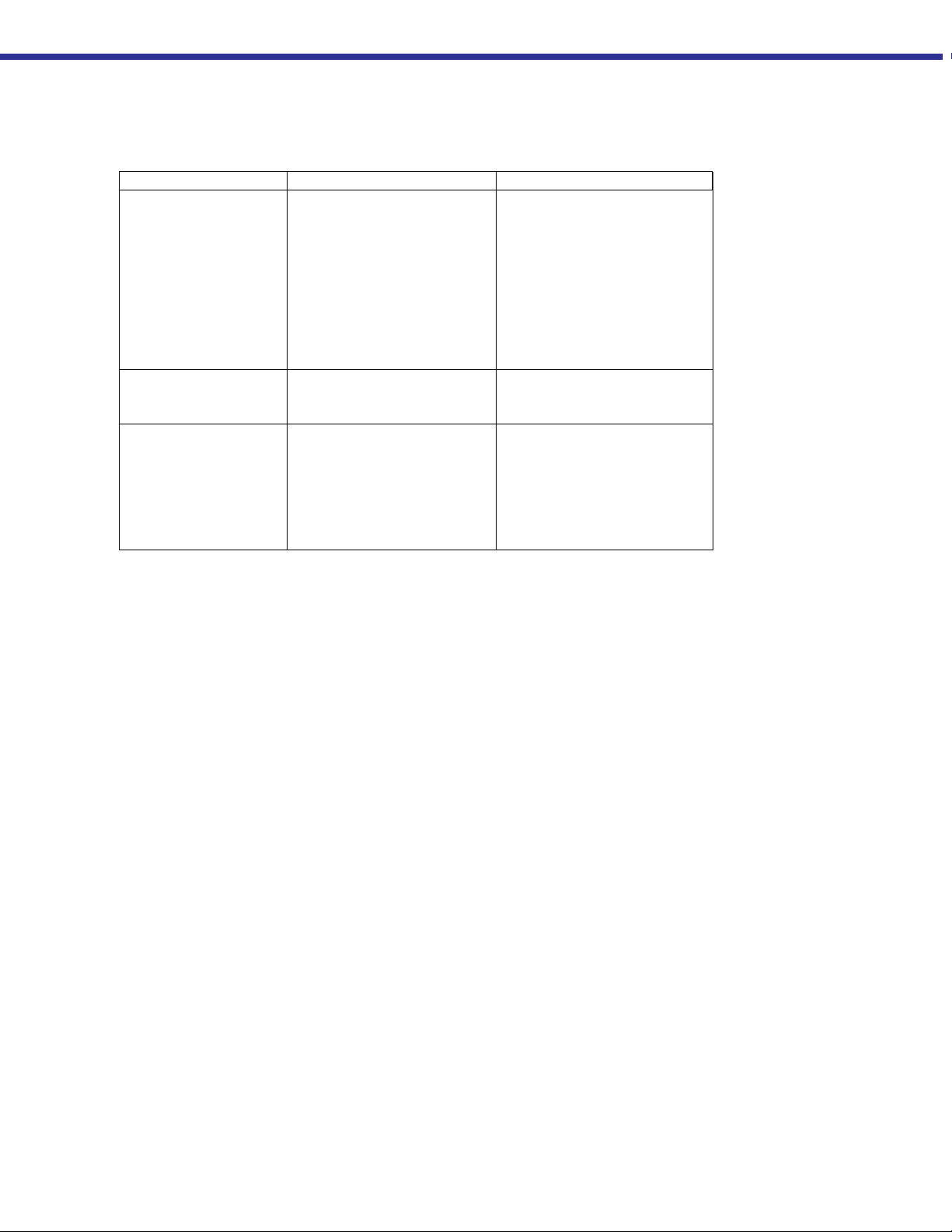
TROUBLESHOOTING
Symptom Possible Cause Corrective Action
Frost on bottom of
easy
carb™
1. Frost may appear
during periods of
1. None required.
high use – this is
normal
2. Leak in beverage
2. Repair leak.
system.
Frost on bottom of
carb
™
and
easy
Pressure over125 psig
Pressure Building circuit
incorrectly adjusted.
Readjust regulator (See
Maintenance Section).
(8.6 bar/862 kPa)
Frost on easycarb™
and container is
noticeably cold over
Loss of container
vacuum.
See “Checking Container
Performance” in Maintenance
Section.
entire outer surface.
Low supply pressure -
Out of CO
2
Call supplier for f ill.
Container level gauge
shows zero
Low supply pressure –
easy
carb
™ pressure
OK.
Low tank pressure –
below 125 psig (8.6
bar/862 kPa)
No frost on unit.
1. Supply line regulator
incorrectly set.
2. Supply line leaking
3. USE valve on tank
closed
4. Leak in beverage
system.
5. Restriction in gas
supply line.
1. Pressure building
circuit set too low.
2. Isolation valves
closed.
1. Reset to 90 psig (6.2
bar/621 kPa) or required
supply Pressure.
2. Repair leak.
3. Open Valve.
4. Repair leak.
5. Close USE and PB valve
and o
en beverage line at
a convenient point to
isolation restriction.
1. Readjust regulator ( See
Maintenance Section).
2. Open USE valve and
P.B.
valve. Handle should be
parallel with line.
High carbon dioxide
Leak in system. Repair leaks.
consumption.
easy
™ won’t fill. 1. LIQUID valve close d
carb
1. Open valve. Handle
should be parallel with fill
2. Tank already full.
3. Delivery vehicle
pressure too low.
line.
2. None required.
3. Determine cause and
restore
ressure.
Page 15
Symptom Possible Cause Corrective Action
y
g
y
g
Internal easy
Pressure too high –
Container won’t fill
eas
pressure 270 psig
(18.6 bar/1862 kPa).
eas
pressure 300 psig (20
to 20.7 bar/ 1999 to
2068 kPa).
carb
carb
™ ventin
™ ventin
carb
™
1. Customer usage too
low.
2. Pressure building
circuit improperly
adjusted.
3. Customer tank
insulation system
failure.
–
Relief valve stuck open. Replace relief valve.
–
1. Normal relief valve
operation.
2. Pressure building
circuit not closing.
3. Loss of vacuum
1. Vent customer tank
through fill gun to 125
psig (8.6 bar/862 kPa).
2. Readjust regulator (See
Maintenance Section).
3. See “Checking
Container Performance”
in Maintenance Section.
1. None required.
2. See “Pressure Building
Regulator” in
Maintenance Section.
3. NER test.
15
TROUBLESHOOTING
Page 16

16
REPLACEMENT
PARTS
The following replacement parts list is keyed to the accompanying illustrations for
parts identification purposes. All replacement parts should be purchased from TaylorWharton. When placing orders, please use the nomenclature and part numbers in
this section and send written orders to:
Taylor-Wharton FAX: 251-443-2250
4075 Hamilton Blvd. Phone: 251-443-8680
Theodore, AL 36582 In U.S.A. and Canada
U.S.A. (800) TW TANKS (898-2657)
Item Part NumberDescription
1 6916-9352 Check Valve, 1/4" NPT, Brass
2
6816-9927 Street Tee, 1/4", Brass
3
6913-9225 Pipe Away, 1/2" FNPT, Brass
4 6816-0100 Tee, Male Branch, .25 x .25 x .25, NPT, Brass, 300 PSIG
5 6913-9083 ASME Safety Relief Valve, 1/2" NPT, Brass
6 6010-2075 Plug, Pipe, 1/4", Square head, Brass
7
7815-3083 Safety Head, 450 PSIG
8
7355-4780 Connector, Male, 3/8" ODT x 1/4" MNPT, SS
9 6816-9215 Tee, Male Branch, 1/2" x 1/2" OD, Brass
10 6916-7111 Valve, Ball, 3/8" Inch Female
11 6816-9209 Street Tee, 3/8", Brass
12
6913-9075 Relief Valve, 3/8" MNPT, 400 PSIG, Brass
13 6919-9086 Valve, Ball, 1/4" FNPT x 1/4" MNPT
14 7355-4771 Connector, Male, 1/2" ODT x 3/8" MNPT, Brass
15 EC30-9C02 PB Tube
16
8816-1057 Regulator, PB, 125 PSI, 1/4" IN/OUT
17
GL50-9C54 Cover, Liquid Level Gauge
18 8816-1040 Regulator, 90 PSI, 1/4" IN/OUT
19 6460-2025 Washer, Lock, 1/4" STN.STL
20 6114-1088 Screw, Pan HD, .25-20UNC x .62, Brass
21
7702-6207 Pressure Gauge, 0-200 PSIG
22
EC30-9C01 Tube, Safety Vent
23 7701-0083 Gasket, Glass Filled Teflon
24 BC04-9C6 5 Float Gauge
25 7702-6206 Pressure Gauge, 0-400 PSIG
Item No. Model Float Rod Part No.
* EC-150 GL45-9C91
* EC-300 GL45-9C93
* EC-450 GL45-9C97
* EC-600 GL45-9C97
*Not illustrated
Page 17

17
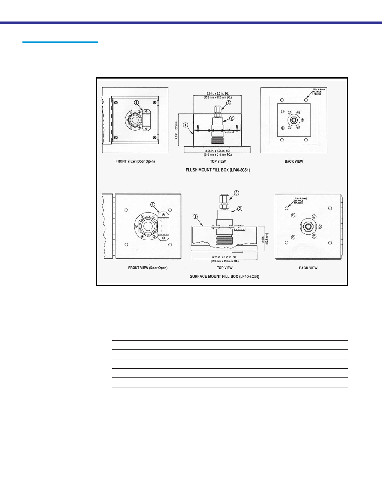
Fill Box
Identification
Item Part Number Description
1 BC04-8C26 Fill Box, Surface Mount
BC04-8C35 Fill Box, Flush Mount
2 6812-9412 Brass Coupling w/mounting flange
3 BC04-8C49 Fill Tube Assembly
* BC04-8C21 Vent Tube Assembly
* 6814-9237 Elbow, Brass 1/2 in. ODT-COMP x 1/2 in ODT-COMP
6 BC04-8C45 Tube Clamp
7 BC04-8C22 Baffle, Vent Tube
8 BC04-8C20 Bracket, Vent Tube
* Not Illustrated
Page 18
18
Optional Fill Box
Identification
Item Part Number Description
1 BC04-8C26 Fill Box, Surface Mount
BC04-8C35 Fill Box, Flush Mount
2 6812-9415 Brass Coupling w/mounting flange, Thread to Connect
3 45702030 Male Connector, 1/2 in. ODT x 1/2 in. NPT Brass
4 BC04-8C22 Baffle, Vent Tube
* 7854-6150 Fill Hose Assembly, 15 ft. (4.5 m)
* 7854-6155 Fill Hose Assembly, 6 ft. (1.8 m)
* Not Illustrated
 Loading...