

Page 1
BT-320
OPERATING AND MAINTENANCE INSTRUCTIONS
10K, 24K, 38K
CRYOSTORAGE SYSTEMS WITH KRYOS CONTROLLER
REVIEW AND UNDERSTAND ALL SAFETY PROCEDURES IN FORM # tw-10 P/N 7950-8052
BEFORE ATTEMPTING TO INSTALL, OPERATE OR PERFORM MAINTENANCE ON THIS
CRYOSTORAGE SYSTEM.
DO NOT ATTEMPT TO USE OR MAINTAIN THIS UNIT UNTIL YOU READ AND UNDERSTAND THESE INSTRUCTIONS. DO NOT PERMIT UNTRAINED PERSONS TO USE OR
MAINTAIN THIS UNIT. IF YOU DO NOT FULLY UNDERSTAND THESE INSTRUCTIONS,
CONTACT YOUR SUPPLIER FOR FURTHER INFORMATION.
Page 2

Note:
For detailed information on the
handling of cryogenic liquids,
refer to the Compressed Gas
Association publication: P-12
“Safe Handling of Cryogenic
Liquids” available from the
Compressed Gas Association
Inc., 1235 Jefferson Davis
Highway, Arlington, VA 2202.
Text Format Notation
In this owner’s manual we use some special text formats to denote certain portions of
the system. These are listed below:
• Menu is indicated in ALL CAPS BOLD.
• Actual Menu Choices are indicated in ALL CAPS.
• Start Fill and Stop Fill sensor are indicated in ALL CAPS ITALICS.
• Specific Menu Descriptions under a main category are listed in Italics.
Safety
Liquefied Gases
Extremely cold refrigerant – Cover Eyes and Exposed Skin – Accidental contact
of the skin or eyes with any cryogenic liquid or cold gas may cause a freezing injury
similar to frostbite. Protect your eyes and cover your skin when handling stored
product and when transferring liquid, or in any instance where the possibility of
contact with liquid, cold pipes, and cold gas may exist. Safety goggles or a face shield
should be worn when transferring liquid. Long-sleeved clothing and gloves that can
be easily removed are recommended for skin protection. Cryogenic liquids are
extremely cold and will be at a temperature of -196ºC (-320ºF) under normal atmospheric pressure.
Keep Equipment Well Ventilated – Although the liquefied gas refrigerant used in
this equipment is non-toxic and non-flammable, it can cause asphyxiation in a confined area without adequate ventilation. An atmosphere that does not contain enough
oxygen for breathing will cause dizziness, unconsciousness, or even death. These
gases cannot be detected by the senses and will be inhaled normally as if they were
air. Ensure there is adequate ventilation where this equipment is used and store liquid
refrigerant supply containers only in a well ventilated area
Liquid Nitrogen System – The liquid nitrogen supply pressure at the inlet to the
refrigerator should be in the range of 10 psig (0.7bar/69 kPa) to 20 psig (1l4bar/138
kPa) for optimum performance. Higher operating pressures will increase transfer
losses and create excessive turbulence of the liquid in the refrigerator which can
generate false signals to the liquid level controller causing the refrigerator to underfill.
In “liquid phase” storage applications, excessive turbulence can cause splashing
which could result in personal injury and/or damage to the refrigerator. When installing piping or fill hose assemblies, make certain a suitable safety relief valve is installed in each section of plumbing between shut-off valves. Trapped liquefied gas will
expand greatly as it warms and may burst hoses or piping causing damage or personal injury. A relief valve is installed in the refrigerator plumbing to protect the line
between the customer supplied shut-off valve and the refrigerator solenoid valve.
Warning: Inlet pressure should not exceed 22 psig (1.5bar/152 kPa).
Higher pressures could result in damage to equipment and/or
sufficient depletion of oxygen in the atmosphere to cause
dizziness, unconsciousness, or death.
Page 3

Note:
Units are supplied with TaylorWharton approved controllers.
If other liquid level controllers
are used, please contact
Taylor-Wharton before putting
the refrigerator into service.
GENERAL INFORMATION
Electrical
Electrical Shock Can Kill – the liquid level controllers used with these refrigerators
operate from 24VAC. However, the external transformer does have a 110/220VAC
primary. Do not attempt any service on these units without disconnecting the electrical power cord.
Freight Damage Precautions
Any Freight damage claims are your responsibility. Cryostorage systems are
delivered to your carrier from Taylor-Wharton’s dock in new condition. When you
receive our product you may expect it to be in that same condition. For your own
protection, take time to visually inspect each shipment in the presence of the carrier’s
agent before you accept delivery. If any damage is observed, make an appropriate
notation on the freight bill. Then, ask the driver to sign the notation before you receive
the equipment. You should decline to accept containers that show damage which
may affect serviceability.
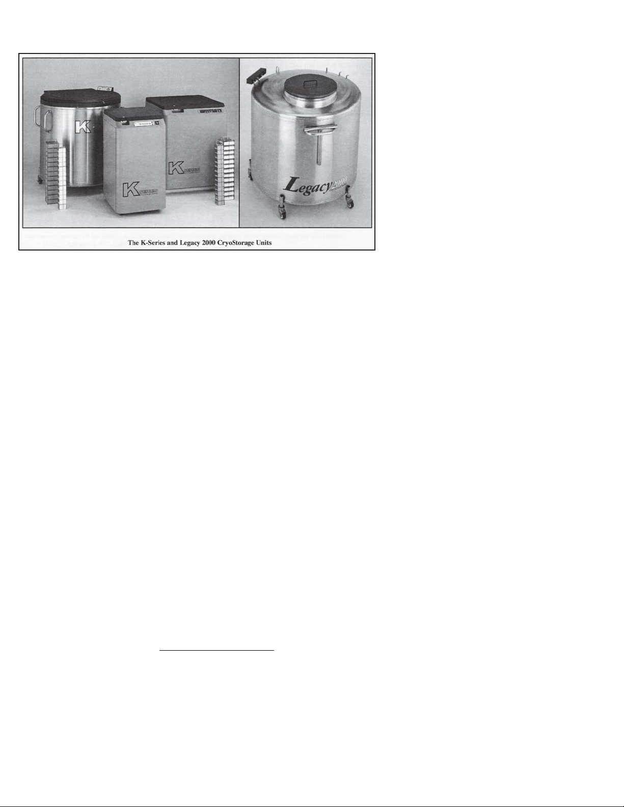
Taylor-Wharton CryoStorage Systems are designed for applications where extremely
low temperature storage of biological products is required. They are also appropriate
for industrial or other applications where liquid nitrogen temperatures and high
capacity are needed.
The 10K, 24K and 38K refrigerators covered by this publication are designed for, but
not limited to, the laboratory environment. The 10K and 24K feature square, modular
cabinets that facilitate grouping several units together in a cryostorage area. The 38K
features a cylindrical stainless steel cryochamber. All of the models will accommodate inventory control systems or provide unobstructed storage area for larger
product. All models are supplied with casters to enable limited mobility for cleaning
purposes.
These standard models are equipped with the KRYOS electronic liquid level controller that will monitor and control the supply of liquid nitrogen to the unit. The controller
features vacuum fluorescent display. The addition of a liquid nitrogen supply and
inventory control racks for systematic retrieval of stored product completes the total
cryostorage system.
Maximum Refrigerator Contents
Your cryostorage system has a maximum weight capacity which is stated in the
specifications. This capacity exceeds the maximum amount of liquid nitrogen the
refrigerator is capable of holding. Generally, as product is added to liquid phase
storage, the stored product and inventory control system are heavier than the liquid
nitrogen they displace. In vapor-phase storage applications, where the liquid refrigerant is found only in the bottom portion of the refrigerator, the weight of contents is
determined more by the weight of the stored product.
Page 4
Liquid nitrogen at atmospheric pressure
weighs 1.78 lb./liter (0.8 kg/liter). To
ensure you are not exceeding the
capacity of the cryostorage system,
calculate the weight of the quantity of
liquid nitrogen in your unit and subtract
the result from the Total Allowable
Capacity Weight found in the specifications section of this publication. All
Taylor-Wharton Gas Equipment
Wharton cryostorage systems are
designed to support the full weight of
liquid nitrogen and a complete stainless
steel or aluminum inventory control
system with boxes and specimens.
CRYOSTORAGE
SPECIFICATIONS
Dimensions
1
Height
in. 44.0 44.0 49.0
mm 1118 1118 1245
Width in. 23.1 34.0 42.0
10K 24K 38K
Depth
2
mm 587 864 1067
in. 30.5 38.0 48.0
mm 775 965 1219
Usable Height, Internal in. 29.0 29.0 29.0
Internal Diameter
3
mm 737 737 737
in. 21.0 31.0 39.0
mm 533 787 991
Capacity
Space Volume cu. ft 5.8 12.7 20.0
cu. m 0.16 0.36 0.56
LN
Capacity L 165 365 590
2
Evaporation Rate
Weight, Empty
4
L/day 5.0 7.0 8.0
lb. 245 405 565
kg 111 184 256
Total Allowable Cap aci ty We ig ht
(including liquid
lb. 292 641 1008
5
refrigerant and stored product)
kg 133 291 457
Maximum Gross Wei ght
6
lb. 540 1050 1575
kg 245 476 715
Inventory Control Sy stem S pe cifi ca tio ns
No 5 x 5 Racks
No. Shelves/Rack 13 13 13
No. 3.0 x 3.0 Racks
No. Shelves/Rack 13 13 13
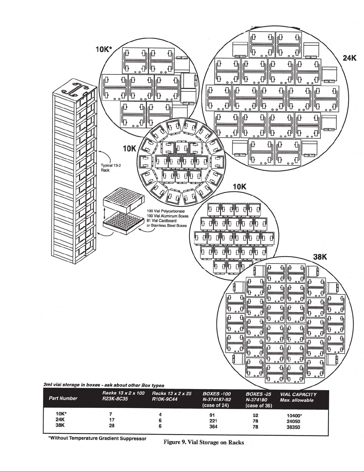
Vial Capacity, 2 ml
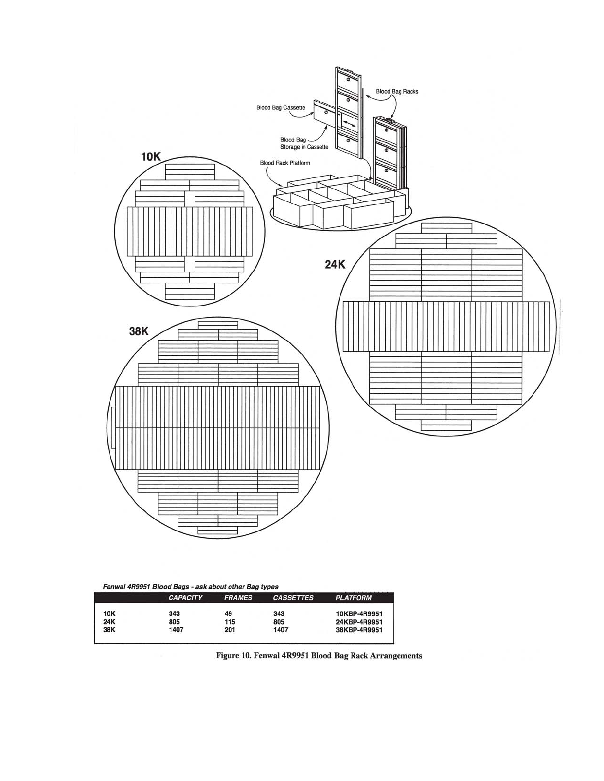
Blood Bag
Straw Capacity
7
8
9
10
11
71728
466
10400 24050 38350
175 360 560
44000 59400 114000
Footnotes:
1
Maximum required clearance (with the lid open) for the 10K is 69 in. (1753 mm); 24K is 76 in (1930
mm); and 38K is 90 in. (2286 mm).
2
Depth with lid open for 10K is 34 in (864 mm); 24K is 48.5 in. (1232 mm); 38K is 55 in. (1397 mm).
3
Temperature Gradient Suppression System reduces internal diameter by approximately ¼ in. (6.4 mm).
Does not apply to 10K.
4
Evaporation rate is nominal. Actual rate may be affected by the nature of the contents, atmospheric
conditions, container history, and manufacturing tolerances.
5
Does not include the weight of the refrigerator itself. Refer to Maximum Refrigerator Contents section.
6
Includes the empty weight and total allowable capacity weight.
7
5 in. x 5 in. (127 mm x 127 mm) 100 cell box.
8
3.0 in. x 3.0 in. (76 mm x 76 mm) 25 cell box.
9
2 ml vial size; 12.5 mm O.D. internal thread.
10
Fenwall 4R-5461 bag.
11
0.5 cc straws, 10 per goblet, 2 13 mm goblets per cane; 2
Page 5

KRYOS Specifications
Configurations: Designed exclusively for the Taylor-Wharton CryoStorage
Systems (10K, 24K and 38K
Power Supply: 24VAC, 40 VA – Standard
16.5 VAC, 40 VA with Battery Backup Option
Sensor Assembly: 4-Thermistor Assembly – Optional
8-Thermistor Assembly – Optional
Freeze-Guard Assembly – Standard
Thermocouples: Operates with none, 1 or 2 Type T
Thermocouples (1 piece standard)
Solenoid Valve: 24 VAC cryogenic solenoid valve – Standard
Control Type: Liquid Level Control or Liquid Level Control with Tempera-
ture Control
Security: Keyless entry via 4-digit password
Power On/Off Password
Menu access Password
Alarms: Activates an audible and a visual alarm. Description of the
alarm condition displays on front panel.
Activates remove alarm after user defined delay
INSTALLATION
Diagnostics: Circuit diagnostics at start-up
Sensor diagnostics from front panel
Thermocouple diagnostics from front panel
Manual Test for audible, visual and remote alarms
Temp. Calibration: Automated calibration from the front panel
Communications: RS-232 Serial Port for 2-way communications capable
Logging Capacity: System Logs (4096 events)
Alarm Logs (4096 events)
Temperature Logs (32,768 events)
Battery: A CR2032 coin cell battery is used to back up time/date
Unpacking and Inspection
Inspect shipping containers for external damage. All claims for damage (apparent or
concealed) or partial loss of shipment must be made in writing within five (5) days
from receipt of goods. If damage or loss is apparent, please notify the shipping agent
immediately.
Open the shipping containers; a packing list is included with the system to simplify
checking that all components, cables, accessories, and manuals were received.
Page 6

Please use the packing list to check off each item as the system is unpacked. Inspect
for damage. Be sure to inventory all components supplied before discarding any
shipping materials. If there is damage to the system during transit, be sure to file
proper claims promptly with the carrier and insurance company. Please advise
Taylor-Wharton of such filings. In case of parts or accessory shortages, advise
Taylor-Wharton immediately. Taylor-Wharton cannot be responsible for any missing
parts unless notified within 60 days of shipment.
Repackaging for Shipment
If it is necessary to return any part of the system for repair or replacement, a Material
Return Authorization (MRA) number must be obtained from an authorized factory
representative before returning the instrument to our service department. Contact
your distributor for return authorization.
When returning an instrument for service, the following information must be provided
before obtaining an MRA:
A. System model and serial number, and controller serial number
B. B. User’s name, company, address, and phone number
C. Malfunction symptoms
D. Description of System
E. Material Return Authorization (MRA) number
If possible, the original packing material should be retained for reshipment. If not
available, consult Taylor-Wharton for shipping and packing instructions. It is the
responsibility of the shipper to assure that the goods are adequately packaged for
return to the factory.
Liquid Nitrogen Supply Connection
The package included with the refrigerator includes a filter and an elbow. The liquid
fill hose from a low pressure source of liquid nitrogen must be connected to the inlet
through these two fittings. This liquid nitrogen source must have a shut-off valve, and
may be any portable liquid cylinder or a bulk supply. The liquid nitrogen supply
pressure at the inlet to the refrigerator should be in the range of 10 psig (0.7 bar/69
kPa) to 20 psig (1.4 bar/38 kPa) for optimum performance. Higher operating pressures will increase transfer losses and create excessive turbulence of the liquid in the
refrigerator which can generate false signals to the liquid level controller causing the
refrigerator to underfill. In “liquid phase” storage applications, excessive turbulence
can cause splashing which could result in person injury and/or damage to the refrigerator.
If the liquid nitrogen supply pressure at the inlet to the refrigerator rises above the
opening pressure of the relief valve on the refrigerator,
charged into the surrounding area which can cause a rapid and very dangerous
depletion of oxygen in the atmosphere. Once this pressure relief device has opened
and cooled to liquid nitrogen temperature, it will not reseat until it has warmed to near
ambient temperature. THIS COULD PERMIT THE ENTIRE CONTENTS OF THE
LIQUID NITROGEN SUPPLY SYSTEM TO BE DISCHARGED INTO THE IMMEDIATE AREA OF THE REFRIGERATOR(S).
WARNING: In order to prevent the relief device on the nitrogen refrigerator(s)
liquid nitrogen will be dis-
Page 7
from opening when the system is in operation, the liquid nitrogen supply
system must be protected
by a pressure relief device
that will open when the
pressure at the inlet to the
refrigerator(s) is approximately 22 psig (1.5 bar/152
kPa). Never install the
supply system pressure
relief device onto a liquid
service line.
Installation
KRYOS Control Field Installation
1. Unplug power from old unit
2. Close liquid nitrogen supply at valve
3. Remove 4 phillips head screws from controller face escutcheon
4. Remove 4 phillips head screws from cabinet top and 2 from old control
5. Withdraw old controller from cabinet top, noting how the controller body has
been resting in guide slots
6. Unplug all jacks and wires from old controller and set aside
7. Remove 4 phillips head screws from real electrical panel
8. Unplug all connectors and wires and set panel aside
9. Remove rear plumbing access panel
10. Disconnect supply hose from solenoid valve using a 7/8 inch wrench
11. Remove old solenoid
Qty Description K-Series
- two ¼ inch hex head screws
- one compression fitting using 3/8 inch wrenches
12. Lower lid and lock hinged lid to cabinet top
13. Raise hinged lid. Cabinet top should also raise out of the way
14. Remove all wire and electrical components other than sensors and thermo-
couple
15. Remove old sensor tube with sensors left in place
16. Mark old sensor locations with electrical tape
17. Measure and made note of the “Start Fill”, “Stop Fill” and temperature sensors
from the bottom of the sensor tube. You will need this information to set up the
new controller.
18. Reverse procedure to install KRYOS control.
1 Control Panel 5140-1166
1 24VAC Wall Transformer R08K-9C04
1 Thermocouple – Temp Sensor R08K-9C51
1 Plumbing R10K-8C64-R
1 Lid Switch 5160-1042
1 Sensor Assembly
•
Freeze-Guard Capable
•
Sensor-T
•
8 Thermistor (option)
•
4 Thermistor (option)
1 Wiring Harness w/Electric Panel 5140-1167
1 Remote Alarm Plug R06K-8C20
1 Operating Instructions 7950-8320
1 Sensor Tube-Perf. S. Steel R23K-9C96
1 Inlet Filter 7631-1075
10, 24
5140-1163
5140-1161
5140-1164
5140-1162
Page 8
WARNING
INLET PRESSURE MUST NOT EXCEED 22 PSIG (1.5 BARL
HIGHER PRESSURES COULD RESULT IN DAMAGE
TO EQUIPMENT AND/OR SUFFICENT DEPETION
OF OXYBEN IN THE ATMOSPERE TO CAUSE
DIZZINESS, UNCONSCIOUSNESS OR EVEN DEATH.
DO NOT REMOVE THIS LABEL
DECAL PART NO. R23K-9C42
Figure 2. Warning Label (R23K-9C42
Filling the Refrigerator (Initial Fill)
The 10K and 24K units using the KRYOS controller come preset from the factory to
operate. For the 38K unit, refer to the Installing the Controller section in this
manual.
The liquid nitrogen supply pressure at the inlet to the refrigerator should be in the
range of 10 psig (0.7 bar/69 kPa) to 20 psig (1.4 bar/138 kPa) for optimum performance. Higher operating pressures will increase transfer losses and create
excessive turbulence of the liquid in the refrigerator which can generate false
signals to the liquid level controller causing the refrigerator to underfill. In “liquid
phase” storage applications, excessive turbulence can cause splashing which
could result in personal injury and/or damage to the refrigerator.
INTRODUCTION
WARNING: Maintain adequate ventilation to prevent asphyxiation hazard
(see Safety Precautions)
Power Supply Connection
Connect the 24 Volt AC power supply to the rear of the cryostorage system; then
plug the power supply into a surge protected 110/120 VAC outlet.
WARNING: If the fill fails to stop for any reason, quickly close the liquid supply
valve to prevent overfilling until the cause of the problem can be
determined.
Thank you for purchasing this product. This state of the art CRYOSTORAGE SYSTEM can control either the liquid level and/or the vapor temperature range. The
features are designed to provide a safe environment for samples while at the same
time tracking all relevant information associated with the freezer. This control provides a complete historical record of the environment in your freezer and therefore,
the environment in which your samples have been stored.
CONTROL COMPONENTS
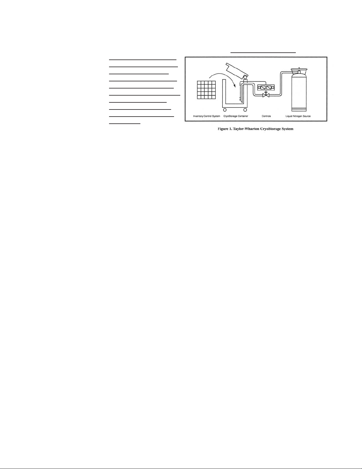
Interface Panel
The KRYOS Interface panel, which the user will interact with, contains the vacuum
fluorescent display as well as the number keypad, power button, help button and the
soft-key control buttons.
Page 9
Main Control
The “brain” for the control system “talks” to the interface unit and makes all
decisions regarding liquid levels, temperatures, valve opening/closing, etc. It is
either housed in a separate box, or located away from the Interface Panel.
Sensor Assembly
A standard 7+1 thermistor assembly, includes the Freeze-Guard over-fill sensor.
Optional 4 thermistor, or 8 thermistor sensor assembly can be ordered. The 4
thermistor assembly maintains the liquid level between 2 middle sensors. The 8
thermistor assembly maintains the liquid level between the high sensor and the
low sensor assigned by the user. The standard 7 thermistor assembly is similar to
an 8 sensor assembly in that the user can select the START FILL and STOP FILL
positions. The eighth position on this assembly is tied into an inline plumbing
thermistor, which detects if the solenoid valve fails to close.
Lid Switch
Is attached to the hinge and determines whether or not the lid is open on the
freezer. This also allows the control to determine whether to active the Quickchill
or Auto Defog features.
Solenoid Valve
Is designed to work with 24 VAC solenoid valves manufactured by Valcor, ParkerHannifin, ASCO or Alcon.
Thermocouples
Type T thermocouples determine the temperature in the freezer. The user may
choose to use NONE, 1 or 2 thermocouples with this control at any time.
Wall Transformer
A 24 VAC, 40 VA wall transformer is required. The system is supplied with a transformer compatible with common household (North American) 110VAC. These wall
transformers have UL approval. UL approval for the system as a whole is not required
since the control operates on such a low voltage. If your power source differs, or is
subject to disruption or line surges due to other equipment on line, consult your
Taylor-Wharton representative.
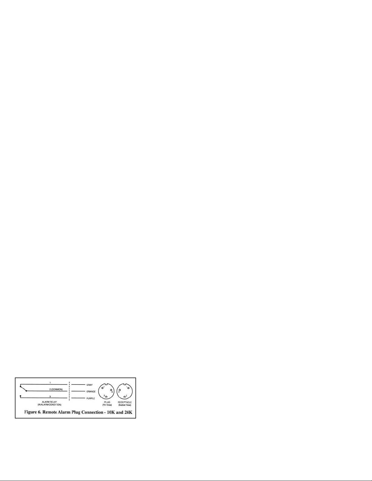
Remote Alarm
If an error condition occurs for a user defined period of time a remote alarm circuit
can be initiated. This is accomplished by connecting a remote device to the remote
alarm jack on the rear electrical panel. The 3-pin jack on the back of the unit provides
continuity between pin #2 (common) and pin #1 in the normal condition. Continuity
between pin #2 and pin #3 is provided in an error condition (See Figure 6).
Page 10
OPERATION
Operating Parameters
When materials are immersed in liquid nitrogen, they will assume the temperature of
the liquid -196ºC (-320ºF). When material is stored in the vapor phase over the liquid,
the liquid nitrogen is still a very cold refrigerant, but the refrigerator’s interior temperature increases somewhat as product is stored higher over the liquid. This temperature
differential is not significant in many biological storage applications, and is affected by
the amount of product stored in the refrigerator, the type and size of inventory control
system, and the liquid level in the unit.
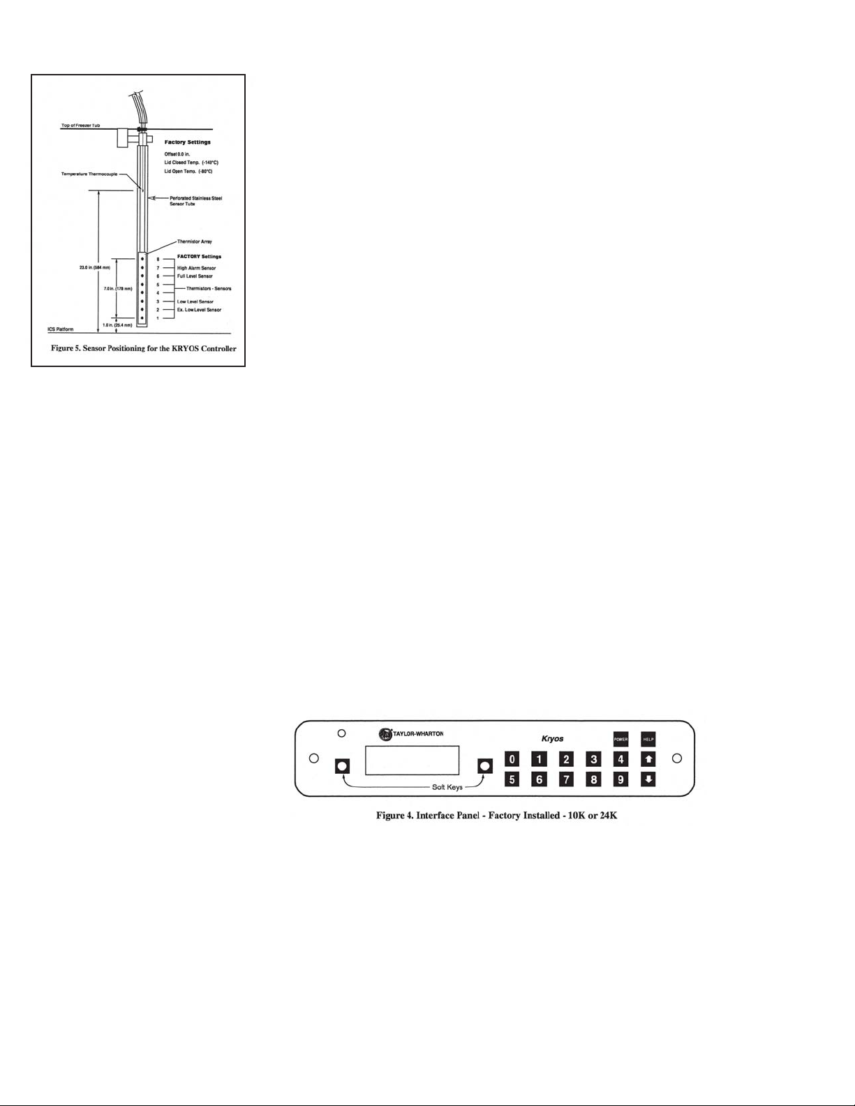
The liquid level in the refrigerator is determined by the position of the sensor probes
in the tube located at the front of the refrigerator. These probes are set at installation
to maintain a specific liquid level. The controller operates a fill cycle that adds liquid at
a low level, fills to a predetermined high level, then stops the fill (See Figure 5). The
cycle repeats when the liquid level drops to the low level sensor over time. Sensor
probe assignments may be changed on the controller keypad to define new high and
low levels, and these levels may be set independently to vary the liquid level differential between fills. Prior to the initial fill of the refrigerator, a determination should be
made whether vapor phase or liquid phase storage will be utilized.
The sensor probe contains seven thermistors that can be preprogrammed for any
liquid level application. The separate sensor in the sensor tube is the temperature
thermocouple. The thermocouple is normally positioned above the High Alarm sensor
to measure the warmest condition in the storage chamber. The factory sensor positions will maintain a liquid level between 3 in. (76 mm) to 6 in. (152 mm). The dimensions used for the factory sensor installation are shown in Figure 5.
Liquid Phase Storage
Liquid phase storage is normally utilized when liquid nitrogen temperatures are
required to maintain stored product viability and the storage medium is adequate for
storage in liquid nitrogen.
In a typical liquid phase storage system, the liquid level sensors are positioned to
maintain the liquid level at or below the top level of the inventory control system.
During operation, the upper levels of the inventory control system will at times become exposed as the liquid level fluctuates.
Care must be taken to ensure that the liquid level remains below the bottom of the
refrigerator lid. Exposure to liquid nitrogen may result in physical damage to the lid.
Additionally, operating the refrigerator with high liquid levels characteristic of liquid
phase storage may result in turbulence during fill cycles. Caution must be exercised if
the refrigerator lid is opened during a fill, and appropriate safety equipment should
always be worn.
Thermocouple Positioning
The thermocouple is a separate sensor designed in conjunction with the
controller temperature readout to monitor and control the temperature
within the refrigerator. The termocouple should be positioned about the
High Level Alarm sensor.
Page 11
NOTE:
Temperature Gradient
Suppression Systems are
specifically designed for use in
vapor phase applications and
will be of little value when
liquid phase storage is used.
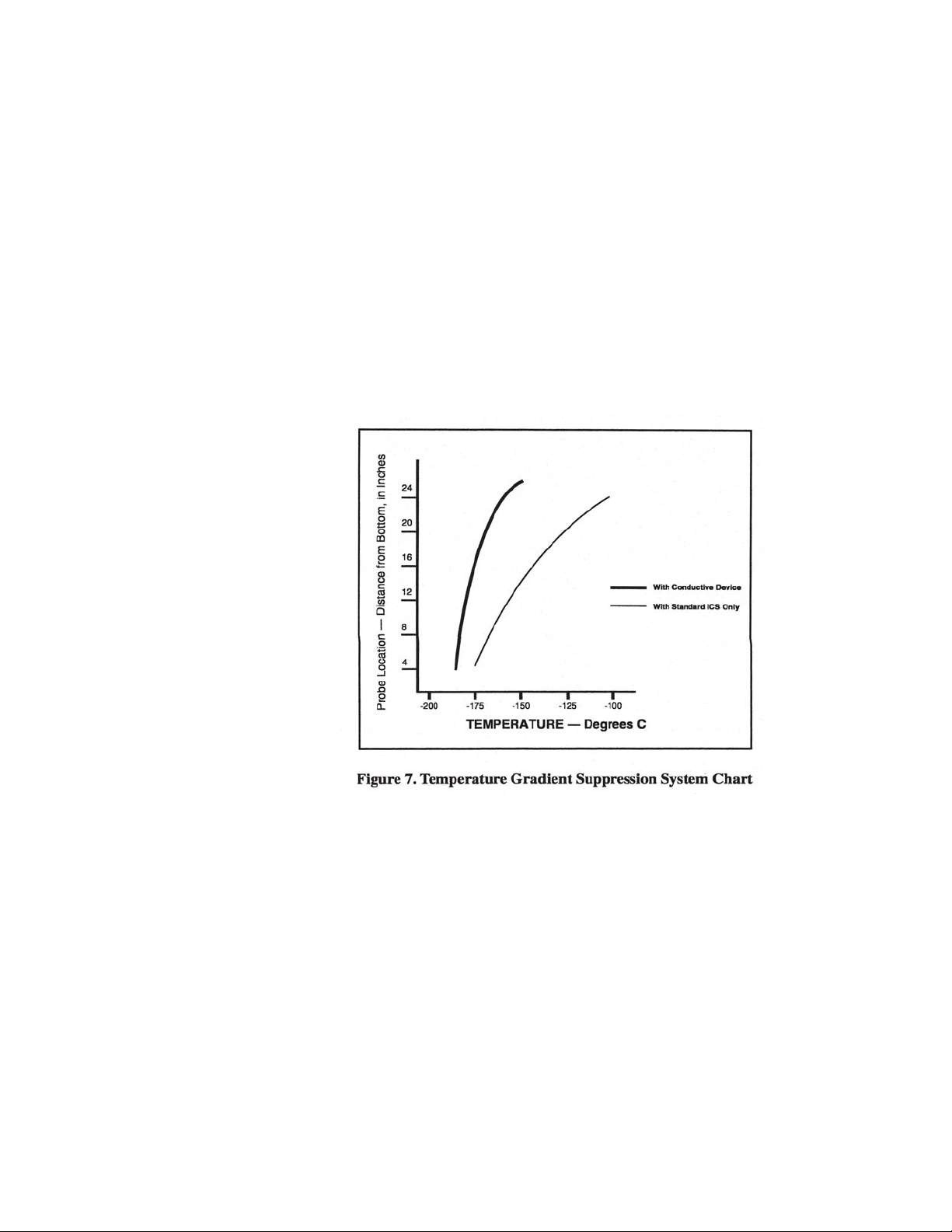
Temperature Gradient Suppression System
Most Taylor-Wharton CryoStorage units include a Temperature Gradient Suppression
System. The Temperature Gradient Suppression System is a thermal conductor
designed to conduct heat downward toward the nitrogen reservoir, and by doing so,
will significantly reduce the temperature gradient between the top of the inventory
control system and the nitrogen reservoir.
While specific temperature profiles will vary with the use of the refrigerator and the
type of inventory control system used, the Temperature Gradient Suppression
System is an effective way to lower the temperature underneath the refrigerator lid
without noticeably increasing liquid nitrogen consumption.
The chart below represents typical temperature gradients within a Taylor-Wharton
CryoStorage System utilizing the Temperature Gradient Suppression System.
Adding an Inventory Control System
The purpose of the inventory control system is to bring order to the storage of many
small samples, and to allow direct retrieval of the particular sample you need at any
time. It is important to be aware that when you lift an ICS rack from the refrigerator it
is in a warmer environment. Learn to locate your sample quickly to avoid unnecessary warming of your stored product.
Keep ICS inserts (drawers or boxes) and dividers in good repair. Replacement inserts
and dividers are available from your Taylor-Wharton distributor to keep your system
as efficient as possible.
Always wear gloves when handling ICS racks or stored product, as they are very cold
– read the precautions in the Safety section of these instructions, and in TaylorWharton publication TW-10 “Handle With Care”, for more detail on handling product
stored in liquid nitrogen.
Page 12
When removing ICS racks to retrieve product, protect the labels, plastic, and electronic areas of the refrigerator from liquid nitrogen that may spill from the rack inserts.
These parts of the refrigerator are subject to damage from the extreme low temperature of the refrigerant.
If an alternate platform is supplied with your inventory control system, the liquid phase
platform in the bottom of your refrigerator may need to be removed to accommodate
your inventory control system platform.
Fully removing Inventory Control System racks such that frost forms on them, and
then setting this frost, along with the racks back into the freezer, will deposit the frost
in the bottom of the freezer. Do not let ice or debris collect in the bottom of the
freezer. Schedule periodic clean out if racks no longer stand upright.
Page 13
Page 14
Page 15

Page 16

Page 17

CONTROL OPERATION
This section of the operating manual is for Taylor-Wharton approved equipment that
uses the KRYOS controller. For models that use the Mark IL controller refer to
operating manual TW-303, P/N 7950-8303, for the Mark 3 controller refer to operating
manual TW-291, P/N 7950-8291, for the Mark 2L controller refer to operating manual
TW-290, P/N 7950-8290.
Introduction
The KRYOS temperature and LN
uninterrupted, reliable service. This controller will maintain the selected temperature
level controller is designed for easy operation and
2
and liquid level range of LN2 in your refrigerator as well as provide audible and visual
alarms for any alarm conditions that may occur. An “alarm” is any off-normal condition, such as a sensor short or open circuit, a temperature outside of the limit set by
the user, or any other condition that would cause the controller to enter the ALARM
mode. “Events” are lid openings and closings, solenoid valve openings and closing,
and operation of the controller’s relay for remote alarm indication. “Data” refers to
periodic alarm and event logging available at the “Data Output” connection.
The KRYOS controller should require no additional attention to control temperature
and maintain liquid level if an adequate source supply of liquid nitrogen is maintained.
If your protocol calls for you to “top-off” the cryostorage system at the end of a work
day or work week, press the FILL button. The unit will fill to the upper allowable liquid
level and stop automatically. You may choose to manually stop the fill by pressing the
STOP FILLING BUTTON at anytime during the fill.
Normal Fill Cycle
When the refrigerator is filled and the controller is operating, the LOW LEVEL and
LOW ALARM sensors are immersed in liquid nitrogen. Their resistance values are
interpreted by the controller as “in liquid”. At the same time, the FUL LEVEL and the
HIGH LARM sensors are above the liquid pool, sending the controller an “above
liquid” signal. As liquid nitrogen evaporates, the liquid level in the refrigerator drops
slowly until the LOW LEVEL sensor is above the liquid and sends a different signal to
the controller. After a delay sufficient to ensure the signal, the controller interprets this
condition as low liquid and opens the fill solenoid, admitting more liquid nitrogen from
the supply source.
The refrigerator will fill slowly. The fill continues until the STOP FILL SENSOR
SENDS THE CONTROLLER A SIGNAL THAT IT IS NOW IN LIQUID. The controller
will close the liquid supply solenoid to stop the fill. As liquid evaporates, the display
will indicate the liquid is at a normal level as the cycle begins again.
The KRYOS temperature and liquid level controller is designed to support a remote
alarm. Connections are provided on the bottom of the controller chassis for the 38K
and on the back of the refrigerator for the 10K and 24K. See Figure 13.
Power
The control can be turned on and off by pressing the Power button followed by
“42”, as instructed on the display panel. The two-step shutdown is a precaution
against accidental shutdown. Shutdown can also be password protected to prevent
users from turning the system on and off under the security section of this manual.
Page 18

Main Display Screen
The main display screen consists of 4 lines of information.
Line 1: Displays the current status of the control. It indicates if all systems are normal
or if any errors have been detected. Error messages disappear when the error is
corrected.
Line 2: Displays the level sensing in the control. If the 7 thermistor or 8 thermistor
assembly is being used, the control will indicate actual liquid level in the freezer. No
pressure or time calculations are used to measure the liquid level (as on other
controllers). If a 4 thermistor assembly is being used, the control will indicate LOW if
the liquid level is below sensor #2, NORMAL if the liquid level is between sensor #2
and sensor #3, and HIGH if the liquid level is above sensor #3. In addition, LOW
LEVEL ALARM is indicated when the liquid level is below sensor #1 and HIGH
LEVEL ALARM is indicated when liquid level is above sensor #4.
Line 3: Displays the temperature indicated by thermocouple #1 and #2. If either
thermocouple is disabled by the user through the menu system, it is no longer displayed on the front panel. If both termocouples are disabled by the user, line 3 is
blank.
Line 4: Used to annotate (or label) the soft-key buttons and to provide information
about the valve and the lid status. Used to annotate (or label) the soft-key buttons and
to provide information about the valve and the lid status. In the center of the line, a
rotating “baton” provides a visual indication that the control is running and functioning
properly.
The Menu System
Pressing the Soft Key labeled MENU on the front right side of the control will access
the menu system. Choose a menu option by pressing the appropriate number of your
menu choice. If more menu choices are available than will fit on 1 screen (more than
4 choices in this menu section), the left-hand soft-key button will give the “More”
choice. User may select inches or centimeter level reading (menu 2,5) in either 7 or 8
thermistor mode. Pressing this button will give the user the additional menu choices. A
shortcut is available to get to the proper menu choice by pressing the appropriate
number button. The menu choice need not be visible on the screen to select it.
When the menu is accessed, all control functions cease until the control returns to the
main status screen. Therefore, if a fill is occurring and the menu is accessed, the
solenoid valve will close until the menu system is exited and the control is again
displaying the main screen. If the menu system is accessed but not interacted with for
3 minutes, it will automatically revert to the main screen and all functions will resume.
Please note that the menu system can vary slightly depending on the configuration of
the control. Menu choices will be included or excluded depending on the selected
features in the control. This is illustrated in the menu system when the 4 sensor or the
8 sensor probe assembly is being used. The START FILL and STOP FILL sensor
must be physically set when the 4 sensor probe is in use, so the START FILL level
and STOP FILL level menu items are not displayed. When the control is operated
with the 8 sensor assembly, the user can assign the START FILL and STOP FILL
Page 19

DISPLAY MENU MAP
1. Temperature
1.1 Thermocouple Select
2.2 Calibrate Temperature
2.3 Test Temperature System
2. Level Sensing
2.1 Test Level Sensors
2.2 Sensor Positions
2.3 Sensor Positions
2.4 Sensor T ype
2.5 Inch/Metric
3. Alarms
3.1 High-Temp Alarm #1
3.2 High-Temp Alarm #2
3.3 System Alarms
3.4 Test Alarms
4. Logging
4.1 Dump Logs
4.2 Error Logs
4.3 System Logs
2.3.1 Start Fill
2.3.2 Stop Fill
3.3.1 LN2 Supply Alarm
3.3.2 Sensor Error Alarm
3.3.3 Remote Alarm Timer
3.3.4 Lid Open Too Long
3.3.5 Thermocouple Alarm
3.4.1 Test Audible
3.4.2 T est Visual
3.4.3 Test Remote
4.1.1 Dump System Logs
4.1.2 Dump Error Logs
4.1.3 Dump Temp Log #1
4.1.4 Dump Temp Log #2
4.2.1 Sensor Error Logging
4.2.2 Low Supply Logging
4.2.3 Remote Alarm Logging
4.2.4 Open Thermocouple logging
4.2.5 High Temperature Alarm Logging #1
4.2.6 High Temperature Alarm Logging #2
4.3.1 Fill Logging
4.3.2 Lid Action Logging
4.3.3 User Access Logs
4.4 Temperature Logs
4.4.1 Thermocouple #1 Log Rate
4.4.2 Thermocouple #2 Log Rate
4.5 Erase Logs
4.5.1 Erase System Logs
4.5.2 Erase Error Logs
4.5.3 Erase Temperature Log #1
4.5.4 Erase Temperature Log #2
5. Security
5.1 Power-On Password
5.2 Menu Password
6. User Options
6.1 RS-232 Settings
6.1.1 Disable RS-232
6.1.2 Set up RS-232
6.1.2.1 Toggle Handshaking
6.1.2.2 Setting the Baud
6.2 Control Options
6.2.1 Date & Time
6.2.2 Lid/Defog Settings
6.2.2.1 Defog Timer
6.2.2.2 Lid Switch Setup
6.2.2.3 Auto Defog
6.2.2.4 Quick-Chill
6.2.3 Control By Temperature
6.2.3.1 Disable Temperature Control
6.2.3.2 Temperature Control settings
6.2.3.2.1 Control Temperature
6.2.3.2.2 Control Range
6.2.4 Freeze-Guard Options
6.2.4.1 V alve Open Duration
6.2.4.2 V alve De-icing
6.3 Display Brightness
6.4 About this Control
Note:
The Menu System is dynamic. If
some choices are disabled,
related Menu choices will
automatically be suppressed;
i.e., if Thermocouple #2 is
disabled, High Temp Alarm #2
will not appear on screen as an
available selection.
levels with the control key pad without physical intervention to the sensors in the
storage chamber unless you want to change from vapor phase storage to liquid phase
storage.
Help Screens
The Help button provides help to the user at any point in the menu system. The help
message is displayed and the user is then prompted to press a button to return to the
menu system.
Temperature
Thermocouple Select
The chamber temperature is monitored with 1 or 2 T ype T thermocouples. The
thermocouples should be placed in the chamber to monitor temperature in the warm-
Page 20

est part of the chamber (worst case temperature). Factory installation includes one
thermocouple inside of the sensor tube at an elevation to match the height of standard
racks. A second Type T thermocouple may be added to monitor another location
inside the chamber. Both thermocouples can be activated/deactivated through the
menu system. (MENU, 1,1)
Calibrate Temperature
KRYOS provides easy calibration of the thermocouples. To calibrate, the user should
enter the menu system (MENU, 1,2). Remove the thermocouple from the sensor tube
and dip thermocouple #1 into an ice water bath. The fourth line of the control display
will indicate “Wait” and will give a reading on the proximity of the temperature to 0ºC.
When the temperature reaches equilibrium the control will indicate “OK” and the user
can press the left soft-key button. Dry the thermocouple thoroughly. Next, the control
will prompt you to dip thermocouple #1 into LN
to -196ºC (-320ºF). When it does, the control will again indicate “OK” and the user can
. Wait while the control self calibrates
2
again press the left soft-key button. The control will then indicate that the temperature
has been calibrated. The thermocouple is now ready to be repositioned inside the
sensor tube. Be sure that the thermocouple elevation is well below the lid when
closed. Please note that both thermocouples are calibrated by going through this
process with Thermocouple #1.
Test Temperature System
The temperature circuitry can be checked at any time through the menu system
(MENU, 1,3). This check will tell if the thermocouples are working or if they are “open”
(broken or unplugged). If a thermocouple is not connected to the control it will check
as “open.” If a termocouple is “Disabled” through the menu system, it will not show up
on the check.
Level Sensing
The level sensing in the system is determined through the use of thermistor based
sensor assemblies. Thermistors are thermal resistors whose resistances change as
temperature changes. Their use in liquid level control is a time tested method to
provide accurate results. The KRYOS uses a 7, 8 or a 4 thermistor assembly to
measure liquid level in the freezer. The 4 sensor assembly provides general information about liquid level (high alarm, high, normal, and low alarm) while the 7 and 8
thermistor assemblies provide liquid level readings accurate to the nearest inch.
When the LN2 level drops below the START FILL sensor, the control opens the
solenoid valve to commence the fill process. This process continues until the LN
level reaches the STOP FILL sensor. When the control “senses” that the LN2 has
2
reached the upper level, it flashes “Check” on the display while the KRYOS insures
that it has not received false signals and then allows the fill to stop. The fill process
can be halted at any time before it reaches the STOP FILL sensor by manually
pressing the STOP FILLING button.
Test Level Sensors
The sensor assembly can be tested through the menu system as well (MENU, 2,1).
The sensor diagnostics indicates the sensor number and the status (whether in liquid
or gas) of that sensor. If the control is set for an eight thermistor or Freeze-Guard
sensor it will indicate 8 sensors in the diagnostics. Likewise, if it is set for a four
sensor assembly, it will indicate 4 sensors. The status is indicated with either an “O”
Page 21

for open, a “G” for gas or an “L” for liquid. This is an easy means to tell if sensors are
in or out of liquid or if a new sensor assembly is needed (open sensors).
Set Sensors Offset
A sensor offset can be set through the menu system of the control (MENU, 2, 2). The
offset is used if the sensor assembly is raised off the floor of the freezer and the user
wants to read the actual liquid level on the display. An example of this would be a
STOP FILL setting of 23” and a START FILL setting of 20”. The 8 thermistor sensor
assembly would be set so that the bottom of the sensor assembly is raised 18” off the
floor of the freezer. The level would then read from 18” to 26”. The low level alarm
would be set at 19” since the START FILL is 20” and the high level alarm would be
24” since the STOP FILL is 23.” In operation, the liquid level would read between 20”
and 23.” The offset would be set to 18.” The control determines the liquid level by
adding the offset to the number of thermistors in LN
40”.
. The offset can be set from 0 to
2
Sensor Positions
The START FILL and STOP FILL sensor positions can be set through the menu
system of the control (MENU, 2, 3). START FILL and STOP FILL need to be set if an
8 thermistor sensor or the Freeze-Guard sensor is being used. If an offset is being
used, it is added to the sensor position to indicate the correct level of the sensor from
the floor of the freezer. The STOP FILL sensor must always be higher than the
START FILL sensor. Therefore, if START FILL is being increased where it would
pass the STOP FILL point, the STOP FILL is also increased so that it is always 1”
higher than START FILL. The converse is true for the STOP FILL when it is being
decreased. A four thermistor sensor assembly requires that the START FILL and
STOP FILL sensors be physically located at the correct position. Because of this the
menu selection for setting the START FILL and STOP FILL becomes inaccessible
when the 4 thermistor sensor is being used.
Sensor Type
The sensor type can be set through the menu system (MENU, 2, 4). The sensor type
selection should match the sensor type that is being used in the system. This is a 4
sensor, a 7 sensor (Freeze-Guard) or an 8 sensor array.
If the sensor assembly is unplugged and the main control is still on, the display will
indicate that a sensor error has occurred. In addition the level indicated would be 8”
on an 8 sensor assembly, 7” on a Freeze-Guard assembly or “High Alarm” on a 4
sensor assembly. This occurs because the control cannot differentiate between a
very high resistance (when a thermistor is in LN2) and an infinite resistance (when an
open circuit appears in the level sensing circuitry).
Alarms and Error Conditions
The KRYOS control tracks many different conditions in the freezer and therefore, has
a full complement of alarms associated with these different conditions. As alarms
occur, they cause an audible beep as well as a flashing red light. A remote alarm
relay is also triggered following a user designated period of time, after the error
condition occurs, if it is not corrected. In addition, the error condition is displayed on
the top line until the error condition is corrected.
When an error does occur, you may MUTE the audible alarm by pressing the designated button. The audible alarm will then be silent until activated by a new error
Page 22

condition. The red light will continue to flash until all errors are corrected. It can not be
disabled without disconnecting the power supply. The remote alarm will be activated
if the power supply is interrupted.
The High Temperature Alarm for Thermocouple #1 can be set through the menu
system (MENU, 3, 1). This alarm is activated if the temperature rises above the
designated temperature. The alarm temperature can range from 0ºC to -190ºC. It can
also be disabled.
The High Temperature Alarm for Thermocouple #2 can be set through the menu
system (MENU, 3, 2). This alarm is activated if the temperature rises above the
designated temperature. The alarm temperature can range from 0ºC to -190ºC it can
also be disabled.
System Alarms
The Low LN
This alarm is activated if the solenoid valve is not closed within a designated time
Supply Alarm can be set through the menu system (MENU, 3, 3, 1).
2
period after a fill starts. The solenoid valve can be closed either automatically (the
LN2 level reaches the STOP FILL sensor) or manually (the stop fill button is pressed)
to stop the timer which activates this alarm. The possible choices for this alarm are
None, 15, 30, 45, 60 minutes, 2 or 3 hours. This error does not correct itself until the
fill is stopped (the solenoid closes).
The Sensor Error Alarm can be set through the menu system (MENU, 3, 3, 2). This
alarm is activated if the control detects a sensor error such as an open sensor. The
possible choices are ENABLE or DISABLE. An open sensor can be confirmed
through the TEST LEVEL SENSORS option in the menu
system (MENU, 2,1).
The Remote Alarm Timer can be set through the menu
system (MENU, 3,3,3,). This is the amount of time
allowed to pass before the remote alarm relay is triggered
if an error condition is not corrected. The possible choices
are None, Immediate, 30 minutes, 60 minutes or 2 hours.
The Lid Open Too Long Alarm can be set through the menu system (MENU,3,3,4).
This is the amount of time the lid can be opened before it triggers an alarm condition.
The possible choices are None, 1, 2, 5 or 10 minutes.
The Thermocouple Alarm can be set through the menu system (MENU,3,3,5). This
alarm is activated if either thermocouple experiences an open circuit. The possible
choices are ENABLE or DISABLE.
Test Alarms
The audible, visual and remote alarms can be tested at any time by the user through
the menu system (MENU, 3,4). Follow the instructions on the display to hear the
audible “chirping” indicator of an alarm or to see the red LED flash or to trigger an
immediate relay closure of the remote alarm.
Page 23

Logging
The on board memory logging function is one of the most powerful and useful features of the KRYOS control. It provides a historical record for not only your freezer but
also a complete record of the environment in which specimens were stored. Four
separate logs are kept in the control:
1. System log – System logs are events that occur in the system such as lid opening/closing, LN
filling, Quick-Chill, Defog, etc.
2
2. Error log, - Error logs are off-normal conditions detected by the system.
3. Temperature #1 log, 4. Temperature #2 log. The two temperature logs are simply
records of the temperatures recorded by the two thermocouples in the system.
The system and the error log each hold 4096 events while the combined temperature
logs hold an additional 32,765 temperature events. All the logs are kept in non-volatile
memory, meaning that the information is saved regardless of whether the control has
power.
When an event (system, error or temperature) occurs, the control does two things
with the data:
1. It enters the beginning or the conclusion of an event in the internal memory of the
controller.
2. It sends the event data to the serial port of the freezer.
The control consolidates the events in the internal log (combining “start even” /
”conclude event” information to provide one event with duration), however, when the
data is sent to the serial port no consolidation of data occurs.
As an example, a fill would provide one log entry in the internal log of the control,
indicated as follows: Fill occurred on 9/28/98 @ 8:07 for 24 minutes. The same
data coming out of the serial port would cause two entries in a computer or printer
and would be indicated as follows:
Fill Started on 9/28/98 @ 8:07
… (elapsed time)
Fill occurred on 9/28/98 @ 8:07 for 24 minutes
Menu Access causes the control to make some decisions on logging an event and
they are handled in the following manner: Temperature is immediately logged (if it is
enabled) and then a fresh time period is started when the Menu system is exited.
System and error logs are placed in a suspended state until the control exits the
menu system and timing is started again. Duration of system and error logs then are
total time of the event less any time that the user was in the menu system.
When logs are dumped to the serial port, the oldest events are sent first. The control
operates on the FIFO (First In First Out) method.
Page 24

Dump Logs
Dump SYSTEM LOGS is accessible through the menu system of the control (MENU,
4,1,1). This option sends data from the system logs to the serial port of the freezer.
When this option is chosen, the display reports how many system logs are in the
system. While the data is being sent to the serial port, it can be paused or completely
cancelled through the menu system.
DUMP ERROR LOGS is accessible through the menu system of the control (MENU,
4,1,2). This option sends data from the error logs to the serial port of the freezer.
When this option is chosen, the display reports how many error logs are in the
system. While the data is being sent to the serial port, it can be paused or completely
cancelled through the menu system.
DUMP TEMP LOG #1 and TEMP LOG #2 are accessible through the menu system of
the control (MENU, 4,1,3 or MENU, 4,1,4). This option sends data from the temperature logs to the serial port of the freezer. When this option is chosen, the display
reports how many temperature logs are in the system. While the data is being sent to
the serial port, it can be paused or completely cancelled through the menu system.
Error Logs
SENS. ERR. LOGGING is accessible through the menu system of the control
(MENU, 4,2,1). This menu choice turns on/off the logging of all sensor errors. The
choices are ENABLE or DISABLE. Records in the error log.
LOW SUPPLY LOGGING is accessible through the menu system of the control
(MENU, 4,2,2). This menu choice turns on/off the logging of the low LN
The choices are ENABLE or DISABLE. Records in the error log.
supply error.
2
REMOTE ALARM LOGGING Is accessible through the menu system of the control
(MENU, 4,2,3). The menu choice turns on/off the logging of the remote alarm activation. The choices are ENABLE OR DISABLE. Records in the error log.
THERMOCOUPLE OPEN Logging is accessible through the menu system of the
control (MENU, 4,2,4). This menu choice turns on/off the logging of the thermocouple
open alarm. The choices are ENABLE and DISABLE. Records in the error log.
HIGH TEMP #1 LOG is accessible through the menu system of the control (MENU,
4,2,5). This menu choice turns on/off the logging of the high temperature alarm for
Thermocouple #1. The choices are ENABLE and DISABLE. Records in the error log.
HIGH TEMP #2 LOG is accessible through the menu system of the control (MENU,
4,2,6). This menu choice turns on/off the logging of the high temperature alarm for
Thermocouple #2. The choices are ENABLE and DISABLE. Records in the error log.
System Logs
TANK FILL LOGGING is accessible through the menu system of the control (MENU,
4,3,1). This menu choice turns on/off the logging of tank filling operations. The
choices are ENABLE or DISABLE. Records in the system log.
LID OPENING/CLOSING LOGGING is accessible through the menu system of the
control (MENU, 4,3,2). This menu choice turns on/off the logging of lid openings and
Page 25

closings. The choices are ENABLE or DISABLE. Records in the system log.
USER ACCESS LOGGING is accessible through the menu system of the control
(MENU, 4,3,3). This menu choice turns on/off the logging of user access codes,
which are requested when the lid is opened. Records in the system log.
Temperature Logs
Temperature Logging Rates for thermocouple #1 (T/C #1 LOGGING) and thermo-
couple #2 (T/C #2 LOGGING) are accessible through the menu system of the control
MENU, 4,4,1 or MENU, 4,4,2). This menu choice adjusts the rate at which temperatures are logged for the two thermocouples. The possible choices are Disabled, 15,
30 minutes, 1,2,4,6,12 or 24 Hours. Records in the temperature logs.
Erase Logs
ERASE LOGS is accessible through the menu system of the control (MENU, 4, 5).
This menu choice erases any of the four logs found in the control.
once a log has been erased, it is gone forever.
ERASE SYSTEM LOGS (MENU, 4,5,1).
ERASE ERROR LOGS (MENU, 4,5,2).
ERASE TEMPERATURE LOG #1 (MENU, 4,5,3).
ERASE TEMPERATURE LOG #2 (MENU, 4,5,4).
Security
KRYOS security features restrict access to certain key features such as power and
the menu system.
Please note that
The POWER-ON PASSWORD can be set through the menu system of the control
(MENU, 5,1). The power-on password requires entry of a 4 digit password before
turning on or turning off the control. Follow the directions on the display to set a new
password or disable a password. Password 9999 is an invalid choice since this is
used to access the procedure to clear the password if it is forgotten.
The MENU PASSWORD can be set through the menu system of the control (MENU,
5,2). The menu password requires entry of a 4 digit password before allowing access
to the menu system to change any control settings. Follow the directions on the
display to set a new password or to disable a password. Password 9999 is an invalid
choice since this is used to access the procedure to clear the password if it is forgotten.
When the menu password is active, it is possible to review all of the control settings
without having the password. When a password is activated and the user presses the
menu key, two choices are available:
1) MENU (PASSWD REQ)
2) CONTROL SETTINGS
By selecting choice #2 the user can go through the menu system and see all of the
settings in the control. In this mode, the user cannot change any settings.
If either the power-on or the menu passwords are forgotten, the user can reset the
Page 26

password by typing in 9999 when asked for the password, KRYOS will display an 8digit number. Call your distributor or Taylor-Wharton with the 8-digit number to obtain
a unique 8-digit number to type into the control. When this number is entered, the
passwords will be cleared and full access to the control is restored.
User Options
The user options menu choice covers all other control settings not already covered.
These include serial port settings, date and time settings, Lid Settings, Defog, QuickChill, Temperature Control, Valve Freeze-Guard, Display brightness and Control
Information.
Serial Communications and RS-232 Settings
The KRYOS control system is designed with a 2-way serial communication feature.
RS-232 (MENU, 6,1) allows the user to configure the serial port to “talk” with other
Data Terminal Equipment (DTE). The control can send data through it’s serial port to
a computer, a printer or a modem. System logs, error logs or temperature logs are
always available for download. In addition to downloading data the control can accept
commands through the serial port. Control settings can be viewed or changed at any
time. Also remote diagnostics can be performed.
If the RS-232 is enabled the handshaking can be turned on and off. This feature
allows two devices to communicate when sending data. Also the baud rate can be
set. The following speeds can be chosen: 300, 1200, 2400, 4800, 9600 or 19200
baud. For an explanation of remotely detectable alarm conditions, see the “ALARMS”
section of this manual.
Time and Date Set
TIME AND DATE SET can be changed through the menu system. (MENU, 6,2,1).
The date and time will be set at the factory (Central Time, USA), however, different
time zones will need to adjust this according to their time zone. This control is Year
2000 compliant and operation will continue uninterrupted into the Millennium. A coin
cell battery backs up the date and time on the control.
User Access Logs
The USER ACCESS LOGS (MENU, 4,3) track all personnel who enter the freezer by
asking for an identification number. Identification numbers range from 00 to 99. When
this feature is enabled, the control asks for an identification number any time the lid is
opened. An entry is then recorded in the log indicating the time, date and identification of the person entering the freezer. The user has 30 seconds to enter an ID code
(the 30 seconds is counted down on the screen). If an ID is not entered within the 30
seconds time frame, the log indicates that an unidentified user accessed the freezer.
Defog Timer Set
DEFOG TIMER SET can be changed through the menu system of the control
(MENU, 6,2,2,1). This is the time interval that the valve is opened when the user
manually presses the defog button. The possible choices are disabled through 90
seconds.
Manual Defog
The DEFOG TIMER (MENU, 6, 2,2,1) feature provides a burst of LN
clear the fog when the user presses the defog button from the front panel. The
to the freezer to
2
choices for this feature are Disabled through 90 seconds.
Page 27

Lid Switch Setup
LID SWITCH SETUP can be through the menu system of the control (MENU 6,2,2,2).
This option enables or disables the lid switch.
Auto Defog
The AUTO DEFOG (MENU, 6,2,2,3) feature provides a burst of gaseous N
freezer to clear the fog when the lid is opened. This is activated through the lid switch.
to the
2
If the lid switch is deactivated this feature will be disabled. The choices for auto defog
are disabled through 90 seconds.
Auto Defog Timer Set
AUTO DEFOG TIMER SET can be changed through the menu system of the control
(MENU, 6,2,2,3). This option sets the time interval that the valve is opened on an auto
defog (when the lid is opened). The possible choices are Disabled through 90 seconds.
The lid switch must be enabled to use this feature.
Quick-Chill
The QUICK-CHILL (MENU, 6,2,2,4) feature provides a burst of N2 gas to the freezer
to lower the temperature each time the lid has been opened and then closed. This is
activated through the lid switch. If the lid switch is deactivated this feature will be
disabled. The choices for quick-chill are disabled through 90 second purge of gaseous nitrogen.
Quick-Chill Timer Set
QUICK CHILL TIMER SET can be changed through the menu system of the control
(MENU 6,2,2,4). This option sets the time interval that the valve is opened on a quick
chill (when the lid is closed). The possible choices are disabled through 90 seconds.
The lid switch must be enabled to use this feature.
Control By Temperature
CONTROL BY TEMP can be set through the menu system of the control (MENU,
6,2,3). By enabling this option KRYOS will control by temperature around Thermocouple #1. The Temperature Control menu choices are only available if thermocouple
#1 is enabled.
Temperature Control Settings
TEMP CTRL SETTINGS can be set through the menu system of the control (MENU,
6,2,3,2,1). The user can set the temperature that must be maintained in the freezer
around thermocouple #1. The setpoint can be set from -180º to -100ºC.
Control Temperature
KRYOS can also provide a vapor chamber temperature control for specimens that
must be stored in a particular vapor temperature range. The temperature control
function operates in addition to the level control function. The level control always
takes precedence. If the liquid level of LN2 is maintained between the START FILL
sensor and the STOP FILL sensor, the control attempts to maintain a selected
temperature around Thermocouple #1.
Page 28

Control Range
CONTROL RANGE can be accessed through the menu system of the control (MENU,
6,2,3,2,2). KRYOS maintains a temperature range around the user-selected temperature. A tighter range maintains a temperature very close to the selected temperature
at the cost of greater LN
but the LN2 usage is less. The range can be varied from +1º to +15ºC above and
usage. A broad range provides more temperature variability
2
below the selected temperature. The total range therefore, is between 2ºC (1º below
and 1º above the selected temperature) and 30ºC (15º below and 15º above the
selected temperature). When KRYOS is attempting to control by temperature, it
flashes “T.Recov” (Temperature Recovery) in the center of the bottom line.
Freeze-Guard Options
Ice crystals introduced through the supply line is the primary cause of an overfill.
Freeze-Guard is a process designed to reduce the risk of an overfill. Freeze-Guard
consists of two options to reduce the risk of a frozen valve: 1) The maximum valve
open duration can be set by the user. (VALVE OPEN DURATION) 2) The valve can
be rapidly turned on and off trying to free it up (VALVE DE-ICING). Option 2 occurs if
either the Freeze-Guard sensor detects that the valve is not fully closed or if the
control goes into a High Alarm. The special “Freeze-Guard” sensor assembly includes a plumbing “T” with an in-line thermistor which is placed in the plumbing
directly downstream from the solenoid valve. KRYOS monitors the “Freeze-Guard”
thermistor and detects if the flow of LN2 is stopped when the valve has been commanded to close.
Valve Monitoring
If KRYOS detects that a flow of LN2 is occurring even when the solenoid valve is
supposedly closed, an error message will appear on the screen indicating “Valve
Stuck Open.” To confirm, the control waits for 10 seconds after it determines that the
valve should be closed before it will indicate that the valve is stuck open.
Valve Open Duration
Valve Open Duration can be accessed through the menu system (MENU, 6,2,4,1).
This allows the user to set the maximum amount of time, which the valve will stay
open at any one time. If a fill operation exceeds the valve open duration time set by
the user, the valve closes for 15 seconds and then opens again for another cycle.
This 15 second rest period allows the solenoid valve to warm and gives the FreezeGuard sensor the opportunity to predict an impending overfill before it actually
overfills. The allowable settings are Disabled and 1-15 minutes.
Valve De-icing
Valve De-Icing can be accessed through the menu system (MENU, 6,2,4,2). This
feature can be turned on or off. If enabled, the control will try to free up the valve by
rapidly turning it on and off. This feature is triggered when the Freeze-Guard sensor
detects a stuck valve or when the control detects a High Alarm condition. KRYOS will
attempt to free up the valve by De-icing 5 times with a two minute delay between
tries.
Splash-Guard
Splash Guard is a process to reduce or eliminate false signals detected by the
thermistor sensor assembly. In particular this reduces sporadic valve operation when
the sensor assembly is splashed with LN2. When a fill operation has completed
Page 29

because the level has reached the STOP FILL sensor, the display will flash “Check”
and the control will check the validity of the signals received from the sensor assembly. The splash-guard check occurs for 20 seconds and the bottom line of the display
indicates this by flashing “Check”.
Display Brightness
DISPLAY BRIGHTNESS can be set through the menu system of the control (MENU,
6,3). This option changes the intensity of the display. The possible choices are 25%,
50%, 75% and 100%.
INTERFACE SOFTWARE
MAINTENANCE
Control Interface Panel
About this Control
ABOUT THIS CONTROL can be found in the menu system (MENU, 6,4). This option
provides information about the control. In particular it tells the serial number of the
control and the software version that the control is running.
Optional software is available which allows a computer system to communicate with
KRYOS through the serial port on the freezer. The software provides the capability to
download the logs, review control settings, change control settings and perform
system functions such as open/close the solenoid valve, mute the alarm, etc. Contact
Taylor-Wharton for details. Please have your Cryostorage System serial number,
KRYOS serial number and version number as it appears in ABOUT THIS CONTROL
(MENU, 6,4).
Filter Cleaning Instructions
The container will not fill properly if the filter is clogged with ice or dirt. To clean the
filter, first close the supply valve to the refrigerator. Vent the fill line of all pressure.
Remove and warm the filter to ambient temperature. Purge the filter from both directions with dry nitrogen gas or dry oil-free air. Rinse the filter with alcohol and purge it
again with dry nitrogen gas or dry oil-free air to clear contaminants. If the cleaning
process doesn’t clear the blockage, replace with a new filter (P/N 7631-1075).
Page 30

NOTE:
Ice or frost in the sensor tube
may restrict the movement of
sensor probes in the tube. Do
not pull excessively on the
sensor wiring while attempting
to change sensor position. It
may be necessary to remove
the sensor tube from the
container and allow it to thaw
before the sensors can be
repositioned
Defrosting Your K-Series Cryo-Storage System
All liquid nitrogen storage systems are subject to ice and frost buildup over time.
Regular preventive maintenance programs should be instituted to remove ice and
frost from the sensor and fill tubes and from the refrigerator lid.
Ice and frost buildup in the sensor tube may result in false readings being relayed to
the controller from the sensors. Ice can form a thermal barrier around a level sensor,
rendering it insensitive to the temperature differences between vapor and liquid.
Sensors and thermocouples should be carefully removed regularly and inspected for
ice and frost buildup.
Ice and frost buildup in the fill tube may block the flow of liquid nitrogen into the
refrigerator during fill. This blockage can result in the liquid level dropping to dangerously low levels, and may result in the Low Alarm sensor being activated. In addition,
a fill line blockage may cause the Low LN
becomes blocked, it must be warmed until the ice blockage is cleared. Ice blockage
, Supply Alarm to be activated. If the fill line
2
would typically form in the fill tube at the point at which water will form ice. This
location may be just inside the storage chamber, near the top. Warm with a hair dryer
or other safe low heat source with the solenoid in the open position. If this is not
successful in 2 minutes, remove the fill tube from the refrigerator, allow to thaw to
room temperature, and purge with dry nitrogen or oil-free dry air to remove all traces
of moisture before re-installation.
Excessive ice and frost buildup may occur on the refrigerator lid if the lid is left open
or the liquid level is too close to the underside of the lid. To defrost the lid, open the
lid to the fully open position. Clean the ice and frost from the underside of the lid by
allowing it to thaw slightly and wiping with a clean, lint-free cloth. Care must be taken
to insulate the inventory control system from high temperatures, which may affect the
viability of the stored product.
Excessive ice and frost buildup on the lid may occur if the lid is misaligned or the
insulative gasket material is damaged. Should this occur, please contact your TaylorWharton distributor for assistance.
Cleaning Your Taylor-Wharton CryoStorage System
The cryogenic vessel of all K-Series CryoStorage Systems may need to be cleaned
and sterilized if the type of stored product is changed or the unit is taken out of
service. The vessel must be cleaned and sterilized, regardless of the type of stored
product, prior to return to Taylor-Wharton for repair or maintenance
1
To clean and sterilize your K-Series CryoStorage System, first turn the unit off.
Disconnect the power source and the liquid nitrogen source. Remove all stored
product and inventory control system components. Allow the residual liquid nitrogen
to evaporate and the cryogenic vessel to warm to ambient temperature. Increasing air
flow with a room fan or blower will expedite the evaporation.
Spray the entire inner vessel surface with ample amounts of an approved disinfectant.2 Allow surface contact to be maintained for a minimum of five minutes. Rinse the
inner vessel with water, remove all water and debris, and towel dry the surface. Spray
the inner vessel surface with a 70% alcohol to water solution and maintain surface
contact for fifteen minutes. Rinse the inner vessel surface with water and towel dry.
Page 31

WARNING: Never use chlorine-based disinfectants to clean a CryoStorage
System.
Normal Evaporation Rate (NER) Test
Nitrogen consumption is an accumulation of all system components and userintroduced evaporation. The storage chamber is a double walled, vacuum insulated
vessel and contributes to the daily consumption of liquid nitrogen. The liquid nitrogen
supply vessel and transfer hose also contribute greatly to the daily consumption rate.
Choosing to control the vapor temperature, combined with the liquid level and temperature specified, will affect the overall nitrogen consumption. In addition to these
variables, opening the lid to retrieve product, and adding new product into the storage
chamber will pay a role in the accumulative liquid nitrogen consumption.
If the nitrogen consumption of your CryoStorage system seems excessive, it may be
appropriate to perform an estimated Normal Evaporation Rate (NER) test on the
CryoStorage chamber. To perform an NER test:
1. Fill the CryoStorage unit to the “High Level” sensor.
2. Measure the liquid nitrogen level with a plastic or wooden measuring rod.
WARNING: Never use hollow rods or tubes as dip-sticks. When a warm tube
is inserted into liquid nitrogen, liquid will spout from the top of
the tube and may cause personal injury.
3. Close and lock the lid of the CryoStorage System for forty-eight (48 hours.
4. Open the CryoStorage System and measure the liquid nitrogen level. Typically,
liquid nitrogen levels will drop approximately 1 in. (25.4mm) per day. If your
measurement indicates a drop in excess of 2.0 in. (51 mm) per day, please
contact your Taylor-Wharton distributor or Taylor-Wharton for further information.
Please have your serial number, this manual and service history available.
WARNING: The source power supply at 110/120VAC can cause a lethal electri-
cal shock. Unplug the power cord before proceeding with any
repairs.
The KRYOS has been designed for easy setup and maintenance. All connectors on
the controller are uniquely identified snap-on plugs. The thermocouple, sensor
assembly, solenoid valve, power, remote alarm, temperature recorder and data lines
can be connected or disconnected in seconds. For the 10K and 24K, the controller is
connected to the back electrical panel with a wire cable with the appropriate snap-on
connectors.
Removing/Installing the Controller 10K/24K Units
Remove the cabinet top, follow the steps illustrated in Figure 14. Remove two (2)
screws from the controller and lift it from the refrigerator far enough to detach its
electrical connection wiring. Remove four (4) screws from the top of the refrigerator
and lift the cabinet top to gain access to the area between the cabinet and the insulated inner vessel. On the 10K and 24K, the cabinet top may only be raised as shown
because of the lid hinges. Do not remove the hinged lid. After the cabinet top is
loosened and propped up, the electrical connection wiring may be detached to allow
Page 32

access to its back panel connection. At the completion of maintenance or repairs,
reattach the electrical connection wiring to the controller.
To install the controller, install the electrical supply connections panel to the back of
the refrigerator. Feed the wiring harness from the electrical supply connections panel
to the front of the refrigerator and through the opening to where the controller will be
mounted. Attach the electrical supply connections to the controller board. Be sure to
follow all of the installation procedures for the thermocouple, sensor probes and
solenoid valve before you reattach the cabinet top. Reattach the cabinet top with the
(4) four screws that were taken out to remove the cabinet top. Carefully lower the
controller into the cabinet. Attach the controller to the cabinet top with the (2) two
supplied screws. Be sure that all of the necessary installation procedures have been
completed before you start to fill the refrigerator. To start filling, refer to Filling the
Refrigerator (Initial Fill) section of this manual.
38K
Unscrew the two (2) screws that attach the controller to the container. Remove the
controller. Disconnect the thermocouple, sensor probes and solenoid valve leads
from the controller board. After maintenance or repairs have been made to the
controller refer to the procedure outlined for your refrigerator in Removing/Installing
the Controller section.
To install the controller, connect the thermocouple, sensor probes and solenoid valve
leads to the bottom of the controller box.
NOTE:
Ice or frost in the sensor tube
may restrict the movement of
sensor probes in the tube. Do
not pull excessively on the
sensor wiring while attempting
to remove sensors. It may be
necessary to remove the
sensor tube from the container
and allowed it to thaw before
the sensors can be removed.
Locate the two (2) sets of mounting holes on the refrigerator. When facing the container, these holes will be located at the 10o’clock and 2 o’clock positions. Remove
the two (2) screws in the position that has been chosen. Mount the controller to the
outside of container using these two (2) screws. Be sure to follow all of the necessary
installation procedures for the thermocouple, sensor probes and solenoid valve
before you start to fill the refrigerator. To start filling refer to Filling the Refrigerator
(Initial Fill) section of this manual.
Removing/Installing the Thermocouple
Remove the controller using the procedures outlined for your particular refrigerator
model in Removing the Controller section. Disconnect only the thermocouple lead
connection from the controller board. Gently pull the thermocouple from the sensor
tube.
To install a thermocouple, feed the thermocouple lead into the sensor tube to an
elevation in the storage chamber you want to monitor. Connect the thermocouple to
the controller board. At the completion of maintenance or repairs, install the controller
using the procedure outlined for your refrigerator model in the Removing/Installing the
Controller section.
Removing/Installing the Sensor Probes
Remove the controller using the procedures outlined for your particular refrigerator
model in Removing/Installing the Controller section. Disconnect the sensor probe
lead connection from the controller board. Carefully remove the sensor tube plug from
Page 33

the sensor tube and remove the sensor leads from the plug.
Making Adjustments to the KRYOS Sensor Assembly
The factory settings for the KRYOS control system are as follows:
• Low Level Alarm = 2 (Always 1” below the start fill)
• Start Fill Sensor = 3
• Stop Fill Sensor = 6
• High Level Alarm = 7 (Always 1” above the stop fill)
The sensor assembly is pushed to the bottom of the refrigerator as delivered from the
factory. If adjustments need to be made, the following procedure will simplify the
process.
• Determine the range of LN
12)
level in the refrigerator (i.e. Start Fill = 9; Stop Fill =
2
• Determine the appropriate offset by subtracting 2 from the Start Fill. (i.e. Offset =9
–2 = 7)
• Set the sensor assembly so that the very bottom of the assembly matches the
desired offset. This can be done as follows:
• Push the sensor down the sensor tube until it touches the bottom of the refrigerator.
• Mark the sensor wire where it emerges from the top of the sensor tube.
• Using the marked wire as a reference, pull the sensor up the same distance as
the offset setting.
The sensor assembly is now in the correct location.
To make adjustments to a sensor assembly in a refrigerator filled with LN2, the
following procedure can be used:
• Measure the LN2 liquid level in the refrigerator.
• Take this measured level and subtract the offset to determine how many sensors
should be in liquid.
• Go to “Test Level Sensor” through the KRYOS menu (MENU, 2,1). “L” means a
sensor is in liquid while “G” means a sensor is in gas.
• Move the sensor up or down so that the appropriate numbers of sensors are in
liquid (read “L”).
• Get back to the KRYOS main screen and the level indicated should match the
physically measured reading.
The Sensor Offset, the Start Fill and the Stop Fill can all be set through the KRYOS
menu system (MENU, 2).
Making Adjustments to the Kryos Sensor Assembly:
The factory settings for the Kyros control system are as follows:
• Low Level Alarm = 2 (Always 1” below the start fill)
• Start Fill Sensor = 3
• Stop Fill Sensor = 6
• High Level Alarm = 7 (Always 1” above the stop fill)
Page 34

NOTE:
After disconnecting the
solenoid valve leads do not
pull on wire. The wires are tied
and spiral wrapped together
The sensor assembly is pushed to the bottom of the refrigerator as delivered from the
factory. If adjustments need to be made, the following procedure will simplify the
process.
• Determine the range of the LN
= 12)
level in the refrigerator (i.e. Start Fill = 9; Stop Fill
2
• Determine the appropriate offset by subtracting 2 from the Start Fill. (i.e. Offset =
9-2=7)
• Set the sensor assembly so that the very bottom of the assembly matches the
desired offset. This can be done as follows
- Push down the sensor tube until it touches the bottom of the refrigerator.
- Mark the sensor wire where it emerges from the top of the sensor tube.
- Using the marked wire as a reference, pull the sensor up the same distance
as the offset setting. The sensor assembly is now in the correct location.
To make adjustments to a sensor assembly in a refrigerator filled with LN2, the
following procedure can be used:
• Measure the LN2 liquid level in the refrigerator.
• Take this measured level and subtract the offset to determine how many sensors
should be in liquid.
• Go to “Test Level Sensor” through the Kryos menu (MENU, 2, 1). “L” means a
sensor is in liquid while “G” means a sensor is in gas.
• Move the sensor up or down so that the appropriate numbers of sensors are in
liquid (read “L”.)
• Get back to the Kryos man screen and the level indicated should match the
physically measured reading.
The Sensor Offset, the Start Fill and the Stop Fill can all be set through the Kryos
menu system (MENU,2).
Removing/Installing the Solenoid Valve
Remove the controller using the procedures outlined for your particular refrigerator
model in the Removing/Installing the Controller section. Disconnect only the solenoid
valve lead connection from the controller board. Remove the back plumbing cover of
the refrigerator to gain access to the plumbing and solenoid valve.
To remove the solenoid valve loosen the compression fitting that connects the
plumbing tubing to fill tube. Unscrew the two (2) mounting screws that hold the
solenoid valve to the solenoid bracket. Then remove the solenoid valve and its
associated plumbing. Disconnect the plumbing from the inlet and outlet side of the
solenoid valve.
To install a new solenoid valve, attach the connecting plumbing to the inlet and outlet
connections of the valve using Teflon tape. Attach the compression fitting to the fill
tube first and then connect the compression fitting to the elbow that is connected to
the outlet side of the solenoid valve. Position the solenoid valve onto the solenoid
valve bracket and tighten the two (2) mounting screws. Attach the solenoid valve lead
Page 35

connection to the controller board. At the completion of maintenance or repairs, inst all
the controller using the procedure outlined for your refrigerator model in the Removing/Installing the Controller section.
Controller Electrical Tests
If a controller is removed from the refrigerator for service, the liquid refrigerant level
must be maintained manually to protect stored product. The fill solenoid valve will be
inoperative with the controller removed. A flexible fill line terminated with a phase
separator may be used periodically through the open refrigerator lid to conduct
manual fill operations until automatic operation is restored.
Sensor Probes. The sensor probes used to detect liquid level by Taylor-Wharton
controllers are temperature-sensitive resistors called “thermistors.” Their resistance to
electrical current flow changes greatly with their temperature. The resistance of a
typical thermistor used in these controllers varies with its temperature as follows:
• At Room Temperature............................................... 2 ohms to 10 ohms
• In Cold Nitrogen Gas................................................. 8 K ohms to 18 K ohms
• In Liquid Nitrogen...................................................... 18 K ohms to 35K ohms
Controller Logic. The liquid level controllers read the values of the sensors as
indications of liquid level. The function of a sensor, and its value, are interpreted by
solid-state logic circuitry to set normal operating, fill, fill termination, and alarm
conditions. In addition, the refrigerator temperature is monitored and an alarm is
triggered if the temperature raises above a pre-determined point. The following values
will be interpreted by a controller as cause for a logic change – either an alarm, or in
some cases, a fill or fill termination action.
From cold gas to liquid Resistance greater than 22K ohms.
From liquid to cold gas Resistance less than 16K ohms.
Defective Sensor Resistance greater than 50K ohms, or less that 5 ohms.
Page 36

Page 37

Page 38

TROUBLESHOOTING
In addition to the above, an alarm condition may be triggered by an exceedingly long
fill mode.
The key to troubleshooting your CryoSorage system is to determine which component
in the system is the source of the problem. Determine if the problem is occurring in
any of the following subsystems: Supply Vessel, Transfer Line, Power Source,
Temperature, Level Sensing, Security, Lid Switch, Solenoid Valve, Control Display,
Alarm System, Communications. After determining which sub-system is having the
problem, isolate the problem further by performing sub-system tests. Once the
problem is isolated and defined, it will be easier to solve.
Controller Will Not Turn ON
1. Press POWER button. If display is blank and dark go to next step.
2. Check all connections. Start with jacks at the foot of the controller. Pay special
attention to jacks labeled “POWER”. Wall transformer must be plugged into an
outlet providing AC voltage between 100 and 130 to deliver AC voltage 21 to 30
to the back of the freezer.
Indicates High Liquid Level
1. Determine actual liquid level using a dip stick. Select MENU, LEVEL SENSING,
TEST LEVEL SENSORS. An “L” or “G” will indicate individual thermistor status.
“L” meaning that the thermistor is submerged in liquid and “G” indicates that the
thermistor is in cold Gas. Determine the pressure, and remaining liquid level in
the supply cylinder (15 to 22 psi). A fill solenoid valve that freezes (or sticks) open
will typically empty the supply cylinder. Replace solenoid valve if it has failed
even once. Confirm that Relief Valve has a pressure rating of 100psi.
2. Liquid level is sensed by thermistors located in a sensor tube. If the sensor tube
is blocked or iced at the top, the liquid level in the sensor tube may not rise and
fall at the same rate as the liquid level in the freezing chamber. Make sure the
sensor tube is not obstructed.
3. The pool of LN
amplified by the rack arrangement. The deeper the pool, the more turbulent the
can become turbulent during a fill. Bubbling and splashing can be
2
surface of the pool will be during a fill. The turbulence of the pool surface can
splash on the X-High thermistor and cause a false high alarm. Reduce the
splashing.
4. Confirm that sensor assembly is responding to changing liquid level with a diptest.
• Mark the sensor assembly at top of tube to assure re-assembly.
• Close liquid supply valve at source.
• Remove sensor assembly from sensor tube. DO NOT FORCE. Fill solenoid valve
should open and LOW LEVEL alarm should be activated.
• Select MENU, LEVEL SENSING, TEST LEVEL SENSORS. An “L” or “G” will
indicate individual thermistor status. (L = Liquid and G = Gas).
• Dip each thermistor in succession into LN2 Observe the controller display noting
that each thermistor changes from “G” to “L” as each is submerged. Response
time may vary.
• Return to the main menu and submerge the START FILL THERMISTOR IN
Page 39

LIQUID. NOTE THAT THE low level alarm ceases, fill solenoid valve is still open.
Control is flashing FILLING.
• Manually press STOP button and note that the fill solenoid valve closes.
• Press FILL button to re-open fill solenoid valve.
• Continue to lower the sensor until the STOP FILL thermistor is immersed in the
LN
. Thefill should stop after a confirming (CHECK) SPLASH GUARD period.
• Simulate an over fill by lowering the next thermistor into the LN2. HIGH LEVEL
2
alarm should sound with 10 seconds.
• Re-install sensor assembly and thermocouple into sensor tube as before. Open
supply valve on LN2 supply.
Indicates Low LN2 Supply
When the START FILL thermistor is uncovered, the controller calls for the fill solenoid
valve to open. If the STOP FILL thermistor is not covered with LN2 in the pre-determined amount of time, the controller is programmed to interpret this as a LN2 supply
shortage.
1. Check contents gauge and pressure gauge of supply cylinder. Both liquid contents and pressure (15 to 22 psi) are required to complete a fill.
2. Confirm that no other transfer hose or apparatus is attached to the supply cylinder. Either could compromise adequate tank pressure required to complete a fill
in 30 minutes.
• Check the distance that the LN2 must travel to reach the freezer. Observe the
time it takes for Liquid LN2 to reach the Freezer through the usual piping conditions (Pipe-Temperature at start fill). Liquid should be entering the chamber within
4 minutes under normal (usual) line temperature conditions.
• Distances over 6 feet without a gas by-pass are discouraged due to excessive
boil off. Un-insulated fill line for the last 4 feet are encouraged to drive down
vapor temperatures in the freezing chamber during each fill.
• A “Keep-Cold” or a “Keep-Full” device are almost always needed on an LN
pipeline, whether the pipe is Vacuum Jacketed or Foam Insulated.
2
3. Confirm that the solenoid valve is open when a fill is called for.
• If no flow is detected, the solenoid valve is not getting the signal to open, or it is
opening and there is a blockage in the line. Check the connections on the leads
near the solenoid itself, as well as the connector at the controller.
• Confirm that the wires have not been pinched, creating a short circuit. The joint at
the cabinet top to cabinet side is often the pinch point from previous service calls.
4. If a longer fill time is desired, change the setting by selecting: MENU, SYSTEM
ALARMS, LN2 SUPPLY ALARM.
Indicates Open Sensor
1. Normally, this message is associated with a loose plug or connector. Check the
connection at the foot of the controller labeled SENSORS.
2. If the problem persists, the sensor assembly may need to be replaced. To
determine this select: MENU, LEVEL SENSING, TEST LEVEL SENSORS. An
“L”, “G”, or “O” (open) will indicate individual thermistor status. If you still suspect
the controller, confirm the sensor integrity using an ohm meter. Refer to Figurer
15 Pin View Schematics.
• Thermocouple is not repairable. Replace from stock.
Page 40

Temperature reading 10 to 20 degrees warm.
1. Make sure sensor tube is breathing. If Ice build up is a problem in a humid
environment or if you have a clear polycarbonate sensor tube, the thermocouple
may be attached to the outside of the sensor tube with nylon wire ties. Tuck
thermocouple out of harms way on side or back of sensortube. Do Not attach
thermocouple to fill tube.
• Prepare an ice water slurry with crushed ice and tap water. Dip or pour LN
styrofoam cup to prepare an LN2 bath. Calibrate the controller. Select MENU,
into a
2
TEMPERATURE, CALIBRATE TEMPERATURE. Follow the on screen instructions. Hold the thermocouple in each bath until the control completes its selfcalibration.
• Make sure the thermocouple is clean and dry before and after each bath.
• Reposition the thermocouple at the elevation the customer wants to monitor or
control.
Fill Solenoid Cycles On and Off
KRYOS features a Freeze-Guard function where by the valve open duration is
limited, allowed to shut for a short warm-up and then opened again. To confirm or
change the valve open duration:
• Select MENU, USER OPTIONS, CONTROL OPTIONS, FREEZE-GUARD
OPTIONS, VALVE OPEN DURATION.
If the controller detects that the valve is stuck in the open position (i.e., continues to
fill after the valve is de-energized), it will attempt to De-Ice the valve by causing a
rapid cycling of the valve in an attempt to dislodge the blockage.
• To activate or de-activate this feature: Select MENU, USER OPTIONS, CONTROL OPTIONS, FREEZEQUARD OPTIONS, VALVE DE-ICING.
Repeated cycling of the solenoid valve could be attributable to moisture invasion on
the controller circuit board.
1. Check gasket seals.
2. Access control board and allow time to fully dry.
Fill Solenoid Makes Humming Noise
1. Turn fill valve on and off using the control panel. If humming continues, it should
continue to operate reliably. If the noise is excessive, replace solenoid valve.
Transformer Makes Humming Noise
This noise is a normal byproduct of most block transformers. The transformer has a
non-renewable internal fuse to protect the transformer output. If the noise is excessive, replace the transformer.
Display Blanks Our During a Fill
This phenomenon can happen if cold vent gases are spilling into the controller face,
or into the cabinet onto the controller back.
1. Check the seal between the blue lid and the beige cabinet top. The black gasket
Page 41

should direct vent gases out the back of the lid and away from the controller.
• Adjust lid hinges and/or replace gasket.
2. Check seal between top of tub and beige cabinet top. The black gasket should
prevent venting under the cabinet top.
3. Check seal around sensor wires. Tape or spray foam this gap if needed.
Message “Please Wait”
A circuit board malfunction has occurred. Call your authorized Taylor-Wharton agent
for assistance.
Display = “Check”
The word CHECK will flash during periods of Splash-Guard protection. See page 18
for more information.
Lid Open Alarm
A lid switch is located on the left rear hinge. The switch lever should actuate when the
hinge is opened and again when it is shut.
1. Confirm that the two spade connectors are connected to the back of the switch.
They should be attached to the “G” and the “N/C” connections.
2. The switch can be bumped or moved during shipment. Adjust switch up until
closed hinge will actuate switch lever.
QCF (Quick Chill Feature) Will Not Operate
See LID OPEN ALARM
1. To activate or adjust times: Select MENU, USER OPTIONS, CONTROL OPTIONS, LID/DEFOG SETTINGS, QUICK CHILL.
Defog Feature Will Not Operate
See LID OPEN ALARM.
1. To activate or adjust times: Select USER OPTIONS, CONTROL OPTIONS, LID/
DEFOG SETTINGS, AUTO DE-FOG.
Push Buttons Will Not Respond
1. Check all ribbon cable connectors on back of display panel.
2. Moisture may have migrated into the sealed faceplate. Call Taylor-Wharton for a
Return Authorization.
Liquid Level Readout is Incorrect
Liquid level is determined by a seven thermistor assembly inside a protective sensor
tube. The user may adjust the desired START FILL elevations and STOP FILL
elevations for the pool of nitrogen with the confines of the eight inches. The EX-LOW
LEVEL ALARM is automatically assigned to the thermistor below the START FILL
assignment, and the EX-HIGH LEVEL ALARM automatically reserves the thermistor
Page 42

above the STOP FILL thermistor assignment. For this reason START FILL cannot be
assigned to thermistor number 1. Similarly, STOP FILL cannot be assigned to thermistor number 7. The factory installs this seven thermistor assembly all the way to the
floor of the sensor tube, which positions thermistor number 1 one inch above the floor
(i.e.; the first thermistor is offset from the floor zero inches).
1. If you would like to stop the fill at a depth greater than seven inches from the
floor, the sensor assembly must physically be raised inside the sensortube. The
distance that it has been raised becomes the new OFFSET and the controller
must be notified of this offset from the floor. The factory settings are START FILL
at 3 inches and STOP FILL at 6 inches, with an OFFSET of zero. If you want to
establish a START at 15 and STOP at 18, raise the sensor assembly 12 inches
(18 minus 6) and set the controller OFFSET to 12 by: Selecting MENU, LEVEL
SENSING, SET SENSOR OFFSET. The unit should begin filling. The EX LOW
LEVEL sensor has been subjected to the gaseous condition and should sound an
alarm (O.K. to MUTE). Note that in this scenario, you have directed your LN
supply to accomplish up to a 15 inch fill. It may be necessary to stop the fill
2
manually and allow the supply vessel time to regain enough pressure to complete
this exceptionally long fill.
Power Failure Alarm
If power is interrupted, a note of the time and duration will be recorded in the log. No
local alarm will be sounded unless a high temperature is detected after power resumes. The Remote Alarm will be triggered anytime the power is interrupted.
Factory Settings
To restore factory settings at any time KRYOS can be re-initialized. Please note that
a re-initialization clears all logs and passwords and resets settings to those listed in
the table below. To reset factory settings in the control, go to the menu choice
ABOUT THIS CONTROL. (MENU, 6,4) and while looking at this screen type in 1973.
The control will lead you through the process required to reset the factory settings.
Temperature:
Thermocouple #1 Enabled
Thermocouple #2 Disabled
Hi Temp #2 Alarm -100º C
Hi Temp #2 Alarm -100ºC
Level Control:
OFFSET 0 inches
START FILL Sensor 3 inches
STOP FILL Sensor 6 inches
Sensor Assembly Freeze-Guard
System:
RS-232 Enabled
Handshaking CTS/RTS
Baud Rate 19200
Date & Time USA Central Time
Brightness 100%
Defog Timer 15 seconds
Lid Switch Enabled
Auto Defog Timer 15 seconds
Quick-chill 15 seconds
Temperature Control:
Temperature Control Disabled
Temperature -150ºC
Temperature Range +2ºC
Alarms:
LN2 Supply Alarm 30 minutes
Sensor Error Enabled
Remote Alarm 30 minutes
Lid Open Too Long 10 minutes
Thermocouple Open Alarm Enabled
Logging:
Sensor Error Log Enabled
Low LN2 Supply Log Enabled
Remote Alarm Log Enabled
Open Thermocouple Enabled
Hi Temp #1 Log Enabled
Hi Temp #2 Log Enabled
Fill Logging Enabled
Lid Open/Closed Log Enabled
User Access Log Disabled
Thermocouple #1 Rate Log Disabled
Thermocouple #2 Rate Log Disabled
Freeze-Guard:
Valve Open Duration Disabled
Valve De-icing Enabled
Page 43

R
y
REPLACEMENT PARTS
Refrigerator Parts (10K/24K) 10K 24K
Cabinet, Back, Panel ................................................................................................ R10K-9C35 R23K-9C35
Cabinet, Front, Panel ................................................................................................ R10K-9C33 R23K-9C33
Cabinet, Side, Panel...................................................................................... ............ R10K-9C34 R23K-9C34
Cabinet, Top, Panel (old style 24K w/12 o’clock Fill Tube = R23K-9C10) .............. R10K-9C11 R24K-9C12
Gasket Kit .................................................................................................................. R 10K-9C60 R10K-9C60
Lid Assembly (24K for lids prior to PD = R23K-9C85R) .......................................... R10K-9C86 R23K-9C85
Back Cover, Plumbing ......................................... ..................................................... R06K-9C32 R06K-9C32
Caster, (Four Required) ....................... .. ... .... ... .. .. .. ... .. .. ..... .. .. ... .. .. ... .... .. ... .. .. ... .. .... ... 7300-9020 7 300-9020
Fill Tube Assembly (prior to PD fill tube for 24K = R23K-9C66}............................... R10K-9C66 R24K-9C66
Sensor Tube, Perforated, Stainless Steel (field cut to length w/ tube cutter)........... R23K-9C96 R23K-9C96
Pneumatic Spring, Stroke 20# Force for 10K, 40# force for 24K ..... .. .. ... .... ... .. .. .. ... 8958-0130 8958-0140
Hinge, Top Section .................................................................................................... R10K-9C52 R10K-9C52
Hinge, Bottom Section .............................. ................................................................ R17K-9C53 R17K-9C53
Decal, Lid Warning..................................................................................................... R10K-9C42 R17K-9C42
Decal, Warning ......................................................................................................... R23K-9C42 R23K-9C42
Temperature Gradient Suppression System (reduces rack capacity ñ 10K) .......... R10K-9C84 R20K-8C71
Temperature Gradient Suppressor Straps................ .. .. ..... .. .. ... .. .. ..... .. .. ... .. .. ... .... .. ... N/A R20K-8C72
Inventory Control System (ICS) Platform ................................................. ............. ... R10K-9C05 R17K-9C05
Inventory Rack 25 Vials [13 shelves tall for 2 in (51mm.) boxes] (ea.) ................. R10K-9C44 R10K-9C44
Inventory Rack 100 Vials [13 shelves tall for 2 in (51mm.) boxes] (ea.) ............... R23K-8C35 R23K-8C35
Refrigerator Parts (38K) 38K
Lid Assembly ............... .. ... .. .. ..... .. .. ... .. .. ... .... .. ... .. .. .. ... .. ..... .. .. .. ... .. .. ... .... .. ... .. .. .. ... .. ..... R27K -9C00
Caster, (Five Required) ....... ... .... .. ... .. .. .. ... .. ..... .. .. .. ... .. .. ..... .. .. ... .. .. ... .... .. ... .. .. ... .. .... ... 7300-9020
Fill Tube Assembly......................................... ............................................................ R40K-9C36
Sensor Tube, Perforated, Stainless Steel ................................................................ R23K-9C96
Pneumatic Spring, 6 in. (152 mm.) Stroke 90# Force ................ .............................. 8958-0135
Decal, Lid .................................................................................................................. R08K-9C63
Decal, Warning ......................................................................................................... R23K-9C42
Decal, Warning ......................................................................................................... R27K-9C54
Temperature Gradient Suppression System............................................................. R33K-8C71
Temperature Gradient Suppressor Straps................ .. .. ..... .. .. ... .. .. ..... .. .. ... .. .. ..... .. .. ... R33K-8C72
Inventory Control System Platform ........................................................................... R27K-8C00
Inventory Rack 25 Vials [13 shelves tall for 2 in (51mm.) boxes] (ea.) ................. R10K-9C44
Inventory Rack 100 Vials [13 shelves tall for 2 in (51mm.) boxes] (ea.) ............... R23K-8C35
Level Controller Electrical/Mechanical Parts 10K/24K 38K
Control Panel KRYOS ....................................... ....................................................... 5140-1166 5140-1165
Sensor Assembly KRYOS (Freeze-Guard Capable) ............... ................................ 5140-1163 5140-1163
•
Sensor Assembly – Plumbing, Freeze Guard .................................................... 5140-1161 5140-1161
•
8 Thermistor (option) .................................................................. ......................... 5140-1164 5140-1164
•
4 Thermistor (option) .................................................................. ......................... 5140-1162 5140-1162
Remote Alarm Plug.................................................................................................... R06K-8C20 5140-1160
Transformer KRYOS .............................................................. ................................... R08K-9C04 R08K-9C04
Electrical Panel Assembly ............................................... ......................................... 5140-1167 N/A
Thermocouple Assembly .............. ..... .. .. ... .. .. ... .... .. ... .. .. ... .. .. ..... .. .. ... .. .. .. ..... .. ... .. .. .. ... R08K-9C51 R08K-9C51
Lid Switch .................... ... .. .. .. ... .. .. ..... .. .. ... .. .. .. ... .... .. ... .. .. ... .. .. .. ..... .. .. ... .. .. ... .. .... ... .. .. ... 5160-1042 5160-1041
Cable Lid Switch ..................... .. .. .. ... .. .. ... .... .. ... .. .. ... .. .. ..... .. .. .. ... .. .. ... .. .... ... .. .. .. ... .. .. ...
Plumbing Assy. KRYOS 24 VAC .................................................................. ............R10K-8C64-R R38K-8C64-
Solenoid Valve 24 VAC ......... .. ... .... .. ... .. .. .. ..... .. ... .. .. .. ..... .. ... .. .. .. ... .... .. ... .. .. ... 6999-9021 6999-9021
Relief Valve 100 psig (6.9 bar/690kPa) ¼ in. NPT ……………………………………1750-9C90 1750-9C90
Filter Assembl
……………………………………………………………………………7631-1075 7631-1075
Page 44

Fully Auto
-MOWDEN
MARK 1
-GE
MARK 2
-PCR
MARK 2LT
-PCR
MARK 3
-GE
KRYOS
-PCR
CONTROLLER 5140-1128 5140-1145 5140-1131 R08K-9C00 5140-1143 5140-1166
SENSOR ASSEMBLY R06K-9C44 5140-1147 R08K-9C49 R08K-9C01 5140-1137 5140-1163
THERMOCOUPLE R06K-9C46 N/A R08K-9C51 R08K-9C51 R08K-9C51 R08K-9C51
REMOTE ALARM PLUG R06K-8C20 R06K-8C20 NOTE 1 R06K-8C20 R06K-8C20 R06K-8C20
SENSOR TUBE
1
R23K-9C96 R23K-9C96 R23K-9C96 R23K-9C96 R23K-9C96 R23K-9C96
SENSOR TUBE PLUG R10K-9C69 R10K-9C69 R10K-9C69 R10K-9C69 R10K-9C69 R10K-9C69
TRANSFORMER N/A 5140-1146 N/A R08K-9C04 5140-1139 R08K-9C04
ELECTRIC PANEL R06K-9C25 5140-1148 R08K-9C47 R08K-9C02 5140-1142 5140-1167
LID SWITCH N/A 5160-1042 N/A 5160-1042 5160-1042 5160-1042
CABLE, LID SWITCH N/A R23K-9C71 N/A R23K-9C71 R23K-9C71 N/A
PLUMBING ASSEMBLY N/A R23K-8C61 R17K-8C61 R23K-8C62 R24K-8C52 R10K-8C64-R
-SOLENOID VALVE
2
R06K-9C61 6999-9021 R08K-9C48 6999-9021 6999-9021 6999-9021
-RELIEF VALVE, 100 psi 6913-9077 6913-9077 6913-9077 6913-9077 6913-9077 6913-9077
FILTER ASSEMBLY 7631-1075 7631-1075 7631-1075 7631-1075 7631-1075 7631-1075
TEMP. GRADIENT SUP. R10K-9C84 R10K-9C84 R10K-9C84 R10K-9C84 R10K-9C84 R10K-9C84
TGS STRAPS* R06K-9C20 R06K-9C20 R06K-9C20 R06K-9C20 R06K-9C20 N/A
3
Note 1 – Radio Shack Park Number 274-001 Microphone jack.
*No straps on 10K or 18K
1
May require field cut-to-length
2
May require electrical bolt-end-connectors for 18 gauge wire.
3
Includes TGS straps
Fully Auto
-MOWDEN
MARK 1
-GE
MARK 2
-PCR
CONTROLLER 5140-1128 5140-1145 5140-11
THERMOCOUPLE R06K-9C46 N/A R08K-9C
SENSOR ASSEMBLY R06K-9C44 5140-1147 R08K-9C
REMOTE ALARM PLUG R06K-8C20 R06K-8C20 NOTE 1
SENSOR TUBE1 R23K-9C96 R23K-9C96 R23K-9
C
SENSOR TUBE PLUG R10K-9C69 R10K-9C69 R10K-9C
TRANSFORMER N/A 5140-1146 N/A
ELECTRIC PANEL R06K-9C25 5140-1148 R08K-9
C
LID SWITCH N/A 5160-1042 N/A
CABLE, LID SWITCH N/A R23K-9C71 N/A
PLUMBING ASSEMBLY N /A R23K-8C61 R17K-8
C
-SOLENOID VALVE2 R06K-9C61 6999-9021 R08K-9C
-RELIEF VALVE, 100 psi 6913-9077 6913-9077 6913-90
FILTER ASSEMBLY 7631-1075 7631-1075 7631-10
TEMP. GRADIENT SUP.3 R20K-8C70 R20K-8C70 R20K-8C
Note 1 – Radio Shack Park Number 274-001 Microphone jack.
Page 45

Fill in top section at installation. Copy this form each time service is required.
Fill bottom section with service notes to keep a complete log of each freezer service and maintenance history .
End User company Name LOG NO
Service Contract Name/Company
Service Contract Phone Number/Fax
K-series Model/Serial Number
KRYOS Serial Number
Control Version Number
In-service Date
Describe Conditions – Actual
Liquid Level – via Dipstick _____________
Level Sensor Type ____ FG ____ 8T ____ 4T
Lid ____ Open ____ Closed
Filling ____ Yes ____ No
Temperature ________________
LN2 Supply ______ ltr ______ psi
Note: Ice Build-up ____ a little ____ a lot
Note: Gasket condition ____ Seals ____ Leaks
Display Lights ____ On ____ Off
Describe Conditions – Controller Reading
Liquid Level – Per Controller ________________
Liquid Level Setting ____ HIGH ____ LOW
Lid ____ Open ____ Closed
Filling ____ Yes ____ No
Temperature ________________
Supply Alarm ____ On ____ Off
Remote Alarm ____ On ____ Off
Audible Alarm ____ On ____ Off
Temp. control setpoint @ ______ degrees
T aylor-Wharton Technical Services. Phone 800-898-2657 Fax 334-408-4515
Service History Log (note date and log number on each service entry)
Date:
Date:
Date:
Date:
Date:
Date:
Date:
Date:
Date:
Date:
1
All Taylor-Wharton CryoStorage Systems must be cleaned and sterilized prior to return to Taylor-Wharton
for repair or maintenance and must be accompanied by a written statement to this effect. Any K-Service
CryoStorage System received without this statement will be returned to the sender, freight collect. Contact
Customer Service at (334) 443-8680 for information.
2
For cleaning and sterilizing of the K-Series CryoStorage Systems, Taylor-Wharton recommends
EXSPOR™ Cold Sterilant, manufactured by Alcide Corp., 8561 154th Ave, NE, Redmond, WA. (206-882-
2555).
 Loading...