

Page 1

Models RD30 & RC25
Remote Slim-Line
Slush Freezer
Original Operating Instructions
051060--M
11/99 (Original Publication)
(Updated 6/11/12)
Page 2

Complete this page for quick reference when service is required:
Taylor Distributor:
Address:
Phone:
Service:
Parts:
Date of Installation:
Information found on the data label:
Model Number:
Serial Number:
Electrical Specs: Voltage Cycle
Phase
Maximum F use Size: A
Minimum Wire Ampacity: A
E November, 1999 Taylor
All rights reserved.
051060--M
The word Taylor and the Crown design
are registered trademarks in the United States
of America and certain other countries.
Taylor Company
750 N. Blackhawk Blvd.
Rockton, IL 61072
Page 3

Table of Contents
Section 1 To th e Installer 1............................................
Installer Safety 1........................................................
Site Preparation 1.......................................................
Electrical Connections 2.................................................
Beater Rotation 2.......................................................
Refrigerant 3...........................................................
Section 2 To the Operator 7...........................................
Compressor Warranty Disclaimer 7.......................................
Section 3 Safety 8....................................................
Section 4 Operator Parts Identification 10...............................
Section 5 Important: To the Operator 12.................................
Control Switch 12........................................................
Fill Switch 12............................................................
Mix Out Light 12.........................................................
Viscosity Control 12......................................................
Section 6 Operating Procedures 13.....................................
Assembly 13............................................................
Sanitizing 17............................................................
Priming 20..............................................................
Closing Procedure 20....................................................
Draining Product From The Freezing Cylinder 20............................
Rinsing 21..............................................................
Table of Contents Models RD30/RC25
Page 4

Table of Contents -- Page 2
Cleaning 21.............................................................
Disassembly 21..........................................................
Brush Cleaning 22.......................................................
Section 7 Important: Operator Checklist 23..............................
During Cleaning and Sanitizing 23.........................................
Troubleshooting Bacterial Count 23........................................
Regular Maintenance Checks 23...........................................
Winter Storage 23........................................................
Section 8 Troubleshooting Guide 24....................................
Section 9 Parts Replacement Schedule 27...............................
Section 10 Parts List 28.................................................
Wiring Diagrams 37......................................................
Note: Continuing research results in steady improvements; therefore, information
in this manual is subject to change without notice.
Note: Only instructions originating from the factory or its authorized translation
representative(s) are considered to be the original set of instructions.
E November, 1999 Taylor (Original Publication)
(Updated June, 2012)
All rights reserved.
051060--M
The word Taylor and the Crown design
are registered trademarks in the United States
of America and certain other countries.
Models RD30/RC25 Table of Contents
Taylor Company
750 N. Blackhawk Blvd.
Rockton, IL 61072
Page 5
Section 1 To the Installer
The following are general installation instructions. For
complete installation details, please see the check out
card.
cause severe injuries.
Installer Safety
This unit has many sharp edges that can
In all areas of the world, equipment should be
installed in accordance with existing local codes.
Please contact your local authorities if you have any
questions.
Care should be taken to ensure that all basic safety
practices are followed during the installation and
servicing activities related to the installation and
service of Taylor equipment.
S Only authorized Taylor service personnel
should perform installation and repairs on
the equipment.
S Authorized service personnel should consult
OSHA Standard 29CFRI910.147 or the
applicable code of the local area for the
industry standards on lockout/tagout
procedures before beginning any installation
or repairs.
S Authorized service personnel must ensure
that the proper PPE is available and worn
when required during installation and
service.
S Authorized service personnel must remove
all metal jewelry, rings, and watches before
working on electrical equipment.
The main power supply(s) to the freezer must
be disconnected prior to performing any repairs.
Failure to follow this instruction may result in personal
injury or death from electrical shock or hazardous
moving parts as well as poor performance or damage
to the equipment.
Note:Allrepairsmustbeperformedbyan
authorized Taylor Service Technician.
Site Preparation
Review the area the unit is to be installed in before
uncrating the unit, making sure that all possible
hazards the user or equipment may come into have
been addressed.
For Indoor Use Only: This unit is designed to operate
indoors, under normal ambient temperatures of
70_-75_F(21_-24_C). The freezer has successfully
performed in high ambient temperatures of
104_(40_C) at reduced capacities.
This unit must NOT be installed in an area
where a water jet or hose can be used. NEVER use a
water jet or hose to rinse or clean the unit. Failure to
follow this instruction may result in electrocution.
This unit must be installed on a level surface
to avoid the hazard of tipping. Extreme care should be
taken in moving this equipment for any reason. Two or
more persons are required to safely move this unit.
Failure to comply may result in personal injury or
equipment damage.
Uncrate the unit and inspect it for damage. Report any
damage to your Taylor Distributor.
This piece of equipment is made in the USA and has
USA sizes of hardware. All metric conversions are
approximate and vary in size.
081208
Models RD30/RC25 To the Installer
1
Page 6
Electrical Connections
In the United States, this equipment is intended to be
installed in accordance with the National Electrical
Code (NEC), ANSI/NFPA 70-1987. The purpose of the
NEC code is the practical safeguarding of persons and
property from hazards arising from the use of
electricity. This code contains provisions considered
necessary for safety. In all other areas of the world,
equipment should be installed in accordance with the
existing local codes. Please contact your local
authorities.
FOLLOW YOUR LOCAL ELECTRICAL CODES!
Each unit requires one power supply for each data
label on the unit. Check the data label(s) on the freezer
for branch circuit overcurrent protection or fuse, circuit
ampacity, and other electrical specifications. Refer to
the wiring diagram provided inside of the electrical box
for proper power connections.
S Appliances that are permanently connected
to fixed wiring and for which leakage
currents may exceed 10 mA, particularly
when disconnected or not used for long
periods, or during initial installation, shall
have protective devices such as a GFI, to
protect against the leakage of current,
installed by the authorized personnel to the
local codes.
S Supply cords used with this unit shall be
oil-resistant, sheathed flexible cable not
lighter than ordinary polychloroprene or
other equivalent synthetic
elastomer-sheathed cord (Code designation
60245 IEC 57) installed with the proper cord
anchorage to relieve conductors from strain,
including twisting, at the terminals and
protect the insulation of the conductors from
abrasion.
Beater Rotation
CAUTION: THIS EQUIPMENT MUST BE
PROPERLY GROUNDED! FAILURE TO DO SO
CAN RESULT IN SEVERE PERSONAL INJURY
FROM ELECTRICAL SHOCK!
This unit is provided with an equipotential
grounding lug that is to be properly attached to the rear
of the frame by the authorized installer. The installation
location is marked by the equipotential bonding
symbol (5021 of IEC 60417-1) on both the removable
panel and the equipment’s frame.
S Stationary appliances which are not
equipped with a power cord and a plug or
another device to disconnect the appliance
from the power source must have an all-pole
disconnecting device with a contact gap of
at least 3 mm installed in the external
installation.
Beater rotation must be clockwise as viewed
looking into the freezing cylinder.
Note: The following procedures must be
performed by an authorized Taylor service
technician.
To correct the rotation on a three--phase unit,
interchange any two incoming power supply lines at
freezer main terminal block only.
To correct rotation on a single--phase unit, change the
leads inside the beater motor. (Follow the diagram
printedonthemotor.)
Electrical connections are made directly to the splice
box. The splice box is located behind the right side
panel.
120611
2
Models RD30/RC25To the Installer
Page 7
Refrigerant
In consideration of our environment, Taylor
proudly uses only earth friendly HFC refrigerants. The
HFC refrigerant used in this unit is R404A. This
refrigerant is generally considered non-toxic and
non-flammable, with an Ozone Depleting Potential
(ODP) of zero (0).
However, any gas under pressure is potentially
hazardous and must be handled with caution.
Refrigeration Charging and Line
Construction
The dispensing unit is shipped with a refrigerant
holding charge that is sufficient enough to prevent
moisture contamination (8 oz./227 g. R404A). This
holding charge will become part of the total system
charge.
The condensing unit is shipped with the total amount
of refrigerant required for a typical installation of 75 ft.
or less with a single dispenser. For other installation
configurations, use the following chart for line sizing
and for adding required refrigerant.
NEVER fill any refrigerant cylinder completely with
liquid. Filling the cylinder to approximately 80% will
allow for normal expansion.
Use only R134a refrigerant that conforms to
the AHI standard 700 specification. The use of any
other refrigerant may expose users and operators to
unexpected safety hazards.
Refrigerant liquid sprayed onto the skin may
cause serious damage to tissue. Keep eyes and skin
protected. If refrigerant burns should occur, flush
immediately with cold water. If burns are severe, apply
ice packs and contact a physician immediately.
Taylor reminds technicians to be cautious of
government laws regarding refrigerant recovery,
recycling, and reclaiming systems. If you have any
questions regarding these laws, please contact the
factory Service Department.
Recommended System Refrigerant Charge
Domestic
Suction Line
Length
Less than 75 ft. Single 10 lb.
More than 75 ft. Single 12 lb. (add 2 lb.)
Less than 75 ft. Dual 13 lb. (add 3 lb.)
More than 75 ft. Dual 15 lb. (add 5 lb.)
International
Suction Line
Length
Less than 22.8 m Single 4.5 kg
More than 22.8 m Single 5.4 kg (add 0.91 kg)
Less than 22.8 m Dual 5.9 kg (add 1.4 kg)
More than 22.8 m Dual 6.8 kg (add 2.3 kg)
Note: Maximum line length is 150 ft. (45.7 m).
To meet individual installation requirements, lines
must be purchased and constructed locally.
Dispenser Required Charge
Dispenser Required Charge
Line Size
WARNING: R404A refrigerant used in
conjunction with polyolester oils is extremely moisture
absorbent. When opening a refrigeration system, the
maximum time the system is open must not exceed 15
minutes. Cap all open tubing to prevent humid air or
water from being absorbed by the oil.
Models RD30/RC25 To the Installer
Liquid Line -- Single or dual dispensers require 3/8”
refrigerant grade copper tubing (hard or soft).
Note: Insulating the liquid line is recommended if it is
exposed to high ambient conditions. This will reduce
heat accumulation and prevent the formation of flash
gas in the liquid line.
120611
3
Page 8
Single Dispensing Installations
f
Suction Line -- Less than 75 ft. (22.8 m) total line
length requires 5/8” refrigerant grade copper tubing
(hard or soft). Maximum 5/8” tubing length is 75 ft.
(22.8 m).
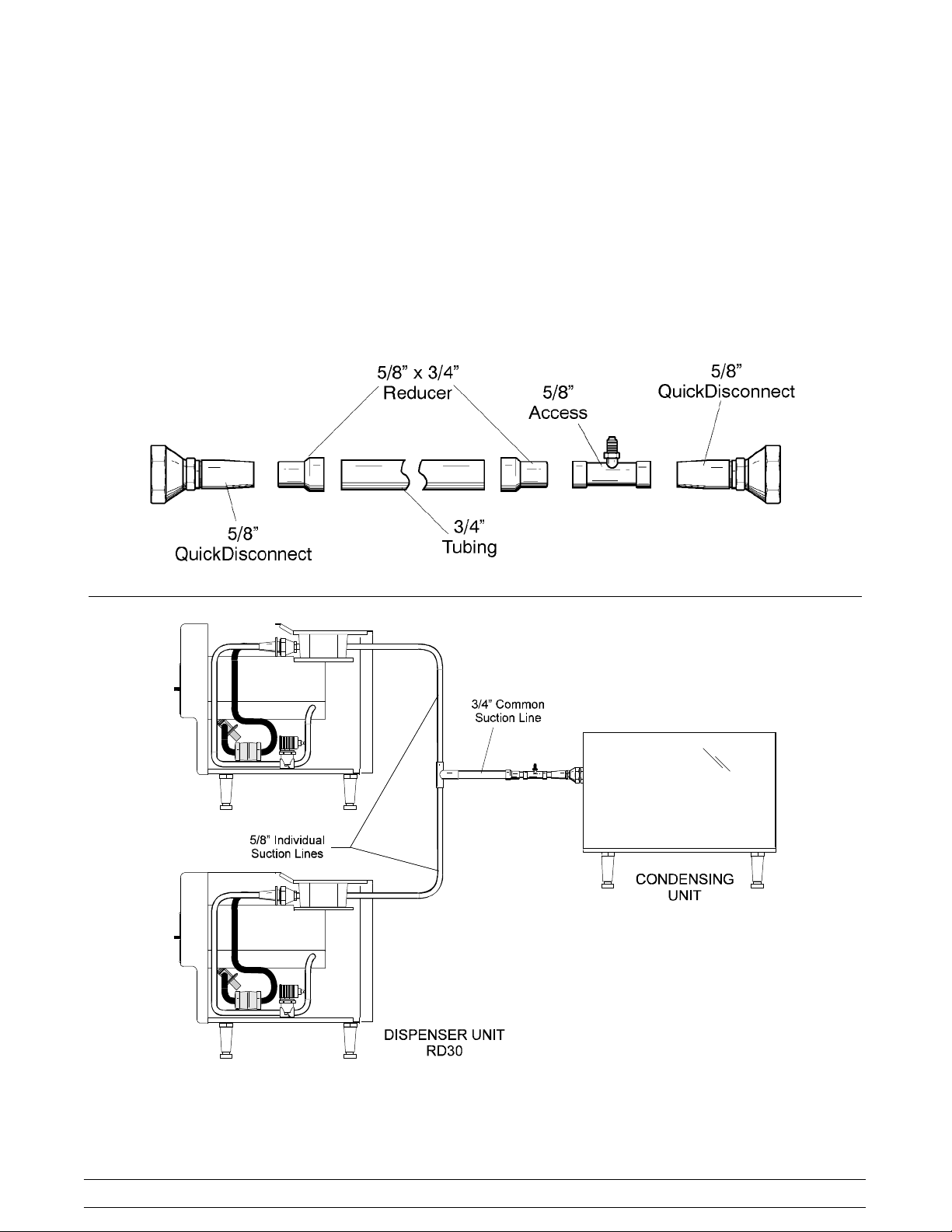
Dual Dispensing Installations
(One Condenser, Two Dispensers)
Individual Suction Line -- Requires 5/8” refrigeration
grade copper tubing (hard or soft) from each dispenser
to the common suction tube.
Note: Suction lines must be insulated.
Suction Line -- More than 75 ft. (22.8 m) total line
length requires 3/4” refrigerant grade copper tubing
(hard or soft). Maximum tubing length is 150 ft.
(45.7 m).
Note: Use 5/8” tubing to attach the quick disconnects to the other fittings.
Common Suction Line -- Requires 3/4” refrigeration
grade copper tubing.
Note: Lines must be insulated and requires a 5/8” x
3/4” reducer fitting at the quick disconnect
connections. See the diagram below.
Note: 5/8” individual line lengths are not to exceed 75 ft. (22.8 m) maximum length each.
Total line length is not to exceed 150
t. (45.7 m). 5/8” line + 5/8” line + 3/4” line = 150 ft. or less.
4
Models RD30/RC25To the Installer
Page 9
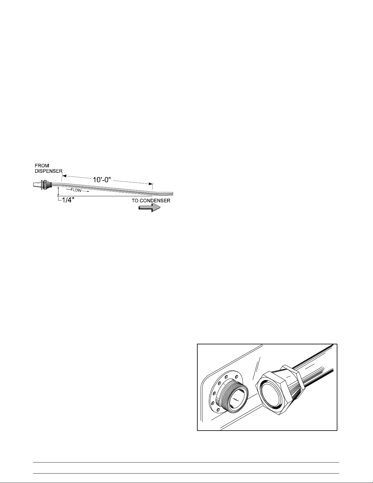
Installation
Step 1
Install refrigeration lines from the dispenser to the
condensing unit. Do not create oil traps.
Note: For proper oil return, installation of horizontal
suction lines are to be sloped downward in the
direction of the condensing unit. The slope must be a
minimum 1/4” (.64 cm.) angle per 10 ft. (3.048 m.) of
line length.
Step 5
Evacuate the field constructed refrigerant lines using
the access fittings brazed on the condensing end of the
refrigeration lines.
Step 6
When the evacuation process is complete, relieve the
vacuum with 4 oz. (113 g.) of HP62 refrigerant per line,
for a total of 8 oz. (227 g.) This procedure will prevent
moisture contamination during dispenser and
condensing unit connection and complete the total
charge.
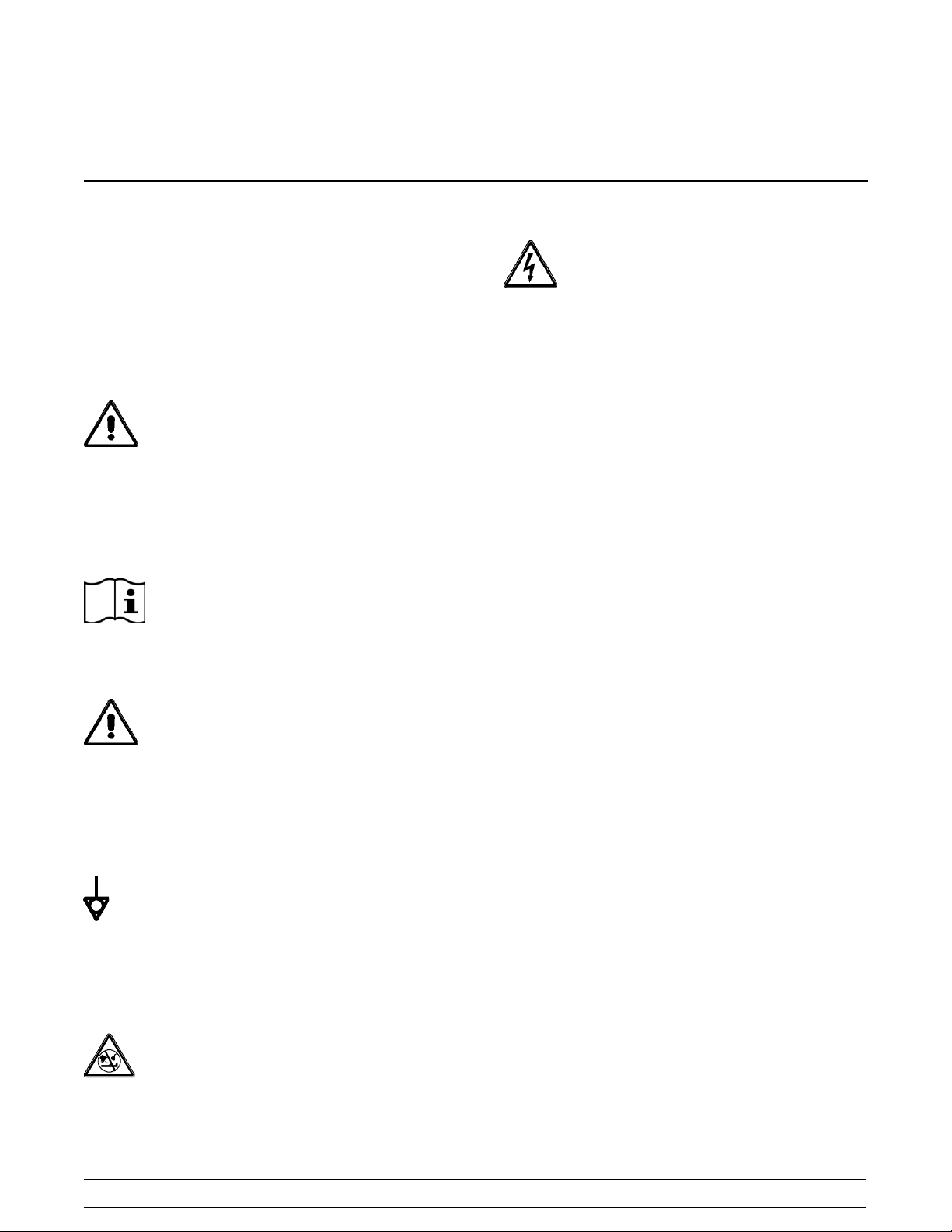
Refrigeration Connections
Connect the refrigerant line quick connect/disconnect
couplings to the mating quick connect/disconnect
couplings on the dispensing and condensing unit.
Step 1
Remove the shipping caps from the quick
connect/disconnect coupling on the dispensing unit.
Step 2
Thoroughly clean and lubricate the mating surfaces of
the quick connect/disconnects.
Note: Use polyolester oil to lubricate the surfaces.
Figure 1
Normally, any straight run of tubing must be supported
near each end of the run. Long runs require additional
supports. As a guide, 3/8” to 3/4” copper should be
supported every 5 ft. When changing directions, no
corner should be left unsupported. Supports should be
placed a maximum of 2 ft. in each direction from the
corner. If soft copper tube is used, make sure it is not
kinked or flattened. If hard drawn copper tubing is
used, use only long radius elbows.
Step 2
Braze the supplied quick connect/disconnect
couplings on the dispenser end of the refrigeration
lines. Couplings are supplied with the dispenser.
Step 3
Braze the quick connect/disconnect couplings and
access tees on the condensing unit end of the
refrigeration lines. Couplings and access tees are
supplied with the unit.
Note: Wrap a wet cloth aroundthe brasscoupling
bodies to prevent heat damage to the seal.
Step 3
Manually thread the coupling halves together to insure
proper mating of the threads.
Step 4
Using proper sized wrenches, tighten the coupling
halves until the round, flat surfaces of inner coupling
bodies completely depress one another.
Step 5
Once the flat surfaces are completely depressed,
tighten the couplings an additional 1/4 turn. This step
is necessary to insure that the knife edge of the seal
seats into the brass seat of the coupling halves,
forming a leak--proof joint (metal seal).
Step 4
Test the field constructed lines for leaks.
Models RD30/RC25 To the Installer
5
Figure 2
Page 10

Step 6
Check all connections for leaks.
Step 7
Insulate all exposed suction line tubing and fittings.
Step 8
Set the pump down switch located in the condensing
unit. For indoor condensing unit application:
Set cut in at 30 PSIG (207 kPa).
Set cut out at 5 PSIG (34 kPa).
For outdoor condensing unit application:
Set cut in at 20 PSIG (138 kPa).
Set cut out at 0 PSIG (0 kPa).
Pump down pressure readings are to be taken at the
refrigeration line access fittings at the condensing unit.
Step 6
Allow the dispenser to run until the condensing unit
cycles off. Verify the proper pump down pressure
switch setting. See Step 8 of “Refrigeration
Connections” (page 6).
Note: Pump down pressure readings are to be taken
at the refrigeration line access fittings near the
condensing unit.
Step 7
If necessary, adjust viscosity to produce satisfactory
product. Adjustments are made by turning the
viscosity adjustment screw (located on the front panel)
clockwise for a thicker product or counterclockwise for
a thinner product.
Set Up Procedures
Standard Fill Module
Step 1
Connect the product supply line to the 1/4” barbed
fitting on the fill module. Adjust the fill system pressure
to deliver product to the hopper at 1.5 to 2.5 oz. (42.5
to 70.9 g) per second. (Approximately 15 to 20 PSIG
[103--138 kPa] for most products.)
Step 2
Lubricate, assemble, sanitize and prime the dispenser
as outlined in the Assembly section of this manual.
Step 3
Place the fill switch in the “ON” position. Allow the
product to fill the cylinder and the hopper until the mix
level float is satisfied.
Step 4
Place the power switch in the “AUTO” position.
Step 5
To observe the suction pressure, attach refrigeration
gauges to the suction access fitting in the dispenser.
Pressures should read approximately 32 psi. (221
kPa) for non--alcoholic application and 28 psi. (193
kPa) for alcoholic application.
Note: Connection to the condensing unit suction
access can give an improper reading.
Units Equipped With Post Mix Valve
Step 1
Connect syrup and water lines.
Note: Adjust the syrup supply pressure to maintain 60
PSIG. Water pressure minimum 40 PSIG, maximum
100 PSIG, may require regulated water supply.
Step 2
Turn the “FILL” switch in the front of the RD30 to the
“ON” position.
Step 3
Press and hold the area on the front of the post mix
valve marked “PUSH” to prime the fill system. Priming
is required until the B.I.B. switch and the float switch
are both satisfied. Priming is complete when product
will flow without pressing the “PUSH” button.
Step 4
To adjust either the syrup or water flow rate, turn the
flow adjustment screw clockwise to increase flow, or
counterclockwise to decrease flow. Adjust the screws
until the desired brix is obtained. The flow rate should
be 1.5 to 2.5 oz. (43 fl. ml.) per second.
Note: Both syrup and water flow adjustment screws
are located inside the post mix valve cover. Viewed
from the front, the syrup adjustment screw is on the
right and water adjustment is on the left.
6
Models RD30/RC25To the Installer
Page 11

Section 2 To the Operator
The freezer you have purchased has been carefully
engineered and manufactured to give you dependable
operation. The T aylor Model RD30/RC25, when
properly operated and cared for, will produce a
consistent quality product. Like all mechanical
products, this machine will require cleaning and
maintenance. A minimum amount of care and
attention is necessary if the operating procedures
outlined in this manual are followed closely.
This Operator’s Manual should be read before
operating or performing any maintenance on your
equipment.
Your Model RD30/RC25 will NOT eventually
compensate and correct for any errors during the
set--up or filling operations. Thus, the initial assembly
and priming procedures are of extreme importance. It
is strongly recommended that all personnel
responsible for the equipment’s operation thoroughly
read this manual.
If you require technical assistance, please contact
your local authorized Taylor Distributor.
Note: Warranty is valid only if the parts are authorized
Taylor parts, purchased from an authorized Taylor
Distributor, and the required service work is provided
by an authorized Taylor service technician. Taylor
reserves the right to deny warranty claims on
equipment or parts if non--approved parts or
refrigerant were installed in the machine, system
modifications were performed beyond factory
recommendations, or it is determined that the failure
was caused by neglect or abuse.
Note: Constant research results in steady
improvements; therefore, information in this
manual is subject to change without notice.
If the crossed out wheeled bin symbol is
affixed to this product, it signifies that this product is
compliant with the EU Directive as well as other similar
legislation in effect after August 13, 2005. Therefore,
it must be collected separately after its use is
completed, and cannot be disposed as unsorted
municipal waste.
The user is responsible for returning the product to the
appropriate collection facility, as specified by your local
code.
For additional information regarding applicable local
laws, please contact the municipal facility and/or local
distributor.
Compressor Warranty Disclaimer
The refrigeration compressor(s) on this machine are
warranted for the term indicated on the warranty card
accompanying this machine. However, due to the
Montreal Protocol and the U.S. Clean Air Act
Amendments of 1990, many new refrigerants are
being tested and developed, thus seeking their way
into the service industry. Some of these new
refrigerants are being advertised as drop--in
replacements for numerous applications. It should be
noted that, in the event of ordinary service to this
machine’s refrigeration system, only the refrigerant
specified on the affixed data label should be used.
The unauthorized use of alternate refrigerants will void
your compressor warranty . It will be the owner’s
responsibility to make this fact known to any technician
he employs.
It should also be noted that Taylor does not warrant the
refrigerant used in its equipment. For example, if the
refrigerant is lost during the course of ordinary service
to this machine, Taylor has no obligation to either
supply or provide its replacement either at billable or
unbillable terms. Taylor does have the obligation to
recommend a suitable replacement if the original
refrigerant is banned, obsoleted, or no longer available
during the five year warranty of the compressor.
Taylor will continue to monitor the industry and test
new alternates as they are being developed. Should a
new alternate prove, through our testing, that it would
be accepted as a drop--in replacement, then the above
disclaimer would become null and void. To find out the
current status of an alternate refrigerant as it relates to
your compressor warranty, call the local Taylor
Distributor or the T aylor Factory. Be prepared to
provide the Model/Serial Number of the unit in
question.
081029
Models RD30/RC25 To the Operator
7
Page 12
Section 3 Safety
We at Taylor Company are concerned about the safety
of the operator when he or she comes in contact with
the freezer and its parts. Taylor has gone to extreme
efforts to design and manufacture built--in safety
features to protect both you and the service technician.
As an example, warning labels have been attached to
the freezer to further point out safety precautions to the
operator.
IMPORTANT -- Failure to adhere to the
following safety precautions may result in severe
personal injury or death. Failure to comply with
these warnings may damage the machine and its
components. Component damage will result in
part replacement expense and service repair
expense.
DO NOT operate the freezer without reading
this Operator Manual. Failure to follow this instruction
may result in equipment damage, poor freezer
performance, health hazards, or personal injury.
Per IEC 60335--1 and its part 2 standards,
“This appliance is to be used only by trained personnel.
It is not intended for use by children or people with
reduced physical, sensory, or mental capabilities, or
lack of experience and knowledge, unless given
supervision or instruction concerning the use of the
appliance by a person responsible for their safety.”
This unit is provided with an equipotential
grounding lug that is to be properly attached to the rear
of the frame by the authorized installer. The installation
location is marked by the equipotential bonding
symbol (5021 of IEC 60417-1) on both the removable
panel and the equipment’s frame.
S DO NOT operate the freezer unless it is
properly grounded.
S DO NOT operate the freezer with larger
fuses than specified on the freezer data
label.
S All repairs must be performed by an
authorized Taylor service technician. The
main power supplies to the machine must
be disconnected prior to performing any
repairs.
S Cord Connected Units: Only Taylor
authorized service technicians may install a
plug on this unit.
S Stationary appliances which are not
equipped with a power cord and a plug or
another device to disconnect the appliance
from the power source must have an all-pole
disconnecting device with a contact gap of
at least 3 mm installed in the external
installation.
S Appliances that are permanently connected
to fixed wiring and for which leakage
currents may exceed 10 mA, particularly
when disconnected or not used for long
periods, or during initial installation, shall
have protective devices such as a GFI, to
protect against the leakage of current,
installed by the authorized personnel to the
local codes.
S Supply cords used with this unit shall be
oil-resistant, sheathed flexible cable not
lighter than ordinary polychloroprene or
other equivalent synthetic
elastomer-sheathed cord (Code designation
60245 IEC 57) installed with the proper cord
anchorage to relieve conductors from strain,
including twisting, at the terminals and
protect the insulation of the conductors from
abrasion.
DO NOT use a water jet to clean or rinse the
freezer. Failure to follow these instructions may result
in serious electrical shock.
110824
Failure to follow these instructions may result in
electrocution. Contact your local authorized Taylor
Distributor for service.
8
Models RD30/RC25Safety
Page 13

S DO NOT allow untrained personnel to
operate this machine.
S DO NOT operate the freezer unless all
service panels and access doors are
restrained with screws.
S DO NOT remove any internal operating
parts (examples: freezer door, beater,
scraper blades, etc.) unless all control
switches are in the OFF position.
Failure to follow these instructions may result in severe
personal injury to fingers or hands from hazardous
moving parts.
This unit has many sharp edges that can
cause severe injuries.
S DO NOT put objects or fingers in the door
spout. This may contaminate the product
and cause severe personal injury from blade
contact.
S USE EXTREME CAUTION when removing
the beater asssembly. The scraper blades
are very sharp.
This freezer must be placed on a level
surface. Failure to comply may result in personal
injury.
Cleaning and sanitizing schedules are
governed by your state or local regulatory agencies
and must be followed accordingly. Please refer to the
cleaning section of this manual for the proper
procedure to clean this unit.
For Indoor Use Only: This unit is designed to operate
indoors, under normal ambient temperatures of 70_ -
75_F(21_ -24_C). The freezer has successfully
performed in high ambient temperatures of
104_(40_C) at reduced capacities.
NOISE LEVEL: Airborne noise emission does not
exceed 78 dB(A) when measured at a distance of 1.0
meter from the surface of the machine and at a height
of 1.6 meters from the floor.
081029
Models RD30/RC25 Safety
9
Page 14

Section 4 Operator Parts Identification
Model RD30
ITEM DESCRIPTION PART NO.
1 Cover--Rear 049201
2 Cover--Hopper 049081
3 Retainer--Clip 049419
4 Panel A.-- Rear X48983
5 Panel--Side--Right 048977
6 Leg A.--4”--3/8--16 Stud w/Cap X43408
7 Panel--Side-- Left 048975
8 Stud--Freezer 034035
ITEM DESCRIPTION PART NO.
9 Washer--Freezer Stud 049032
10 Panel A.--Front X49760
11 Support--Tray--Left 049056
12 Support--Tray--Right 049057
13 Tray A.--Drip X49182
14 Shield--Splash 049203
15 Cover--Front--Upper 049162
16 Cover A.--Solenoid X49396
10
Models RD30/RC25Operator Parts Identification
Page 15

Beater Door Assembly
ITEM DESCRIPTION PART NO.
1 Door Assemb ly--Complete X48768
1a Screw--1/4--20 x 9/16 Thumb 047632
1b Knob--Draw Valve--Black Plastic 047358
1c Plate-- Draw Spout Mounting 049275
1d Spout--Door Zero Waste 049276
1e O--Ring--2.375 OD x 1/16 W 046830
1f Spring--Comp. -- .845 x .055 x 3.5 047357
1g Valve--Draw Zero Waste 047353
1h O--Ring--7/8 OD x .103 W 014402
1i Door A.--Partial X50172
2 O--Ring 5.5” OD x 5.234 ID x .13 049077
3 Bearing--Front 013116
Models RD30/RC25 Operator Parts Identification
ITEM DESCRIPTION PART NO.
4 Arm--Torque 014500
5 O--Ring .291 ID x .080 W 018550
6 Torque Assembly X49022
7 Bearing--Guide 014496
8 Beater A.--7 Qt.--1 Pin Support X46233
9 Blade--Scraper--Plastic 046237
10 Clip--Scraper Blade 046238
11 Shaft--Beater 035418
12 O--Ring 7/8 OD x .139 W 025307
13 Seal--Drive Shaft 032560
14 Nut--Stud 045644
Note: Optional Door Assembly X50654 has a larger
draw valve, spout and door port for thick product.
11
Page 16

Section 5 Important: To the Operator
Control Switch
The control switch is located on the front of the
machine. The center position is “OFF”. The down
position is the “WASH” mode and activates the beater
motor only. The up position is the “AUTO” mode. The
“AUTO” mode activates the beater motor and enables
refrigeration when the fill switch is in the “ON” position.
Fill Switch
The fill switch is located on the front of the machine.
The “ON” position enables refrigeration when the
control switch is in the “AUTO” position. The “ON”
position enables the fill module to replenish and
maintain product levels in the freezing cylinder and in
the hopper. The “OFF” position terminates the fill
function. The refrigeration system is disabledwhen the
fill switch is in the “OFF” position.
Figure 3
Mix Out Light
A mix out indicating light is located on the front panel.
When the light is lit, it indicates that the hopper is
empty and the mix supply must be replenished. When
the indicator lights, refrigeration is automatically
disabled to prevent component damage. The beater
motor continues to run.
Viscosity Control
The viscosity adjustment screw is located on the front
of the unit. The viscosity (thickness) of the slush can
be adjusted by turning the adjustment screw clockwise
for a thicker product or counterclockwise for a thinner
product.
12
Models RD30/RC25Important: To the Operator
Page 17

Section 6 Operating Procedures
We begin our instructions at the point where the parts
are disassembled and laid out to dry from the previous
night’s cleaning.
The following procedures will explain how to assemble
the parts into the freezer, sanitize them, and prime the
freezer with fresh product.
If you are disassembling the machine for the first time
or need information to get to this starting point in our
instructions, turn to “Disassembly” on page 21, and
start there.
Assembly
MAKESURE THE CONTROLSWITCH IS IN
THE OFF POSITION. Failure to do so may resultin
personal injury or component damage.
Note: When lubricating parts, use an approved food
grade lubricant (example: Taylor Lube HP). Every
three months discard rubber parts and install new
rubber parts.
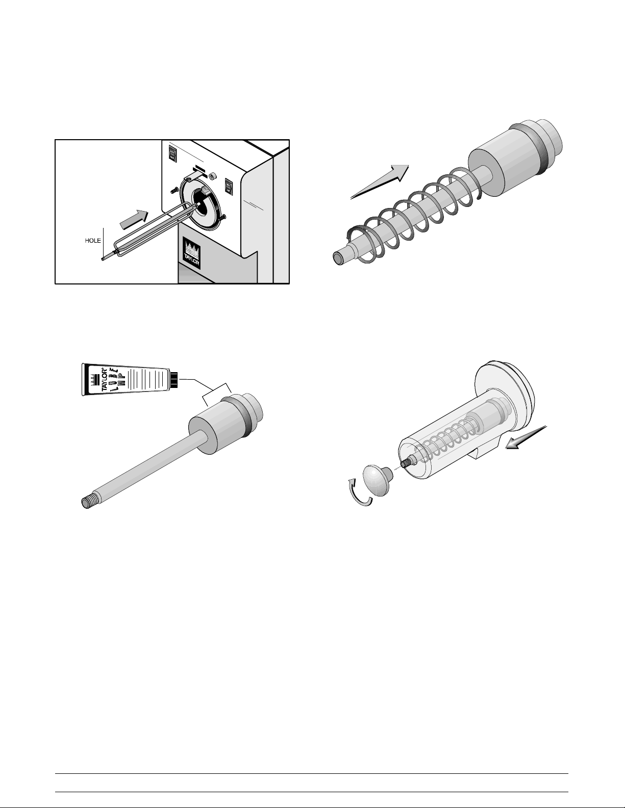
Slide the seal over the shaft until it snaps into the
groove. Fill the inside portion of the seal with lubricant
and evenly lubricate the flat side of the seal that fits
onto the rear shell bearing.
Figure 5
Step 1
Install the beater drive shaft. Lubricate the o--ring
groove. Slide the o--ring into the first groove on the
drive shaft. Lubricate the groove, o--ring and shaft
portion that comes in contact with the rear shell
bearing on the beater drive shaft. DO NOT lubricate
the square end of the drive shaft.
Figure 4
Install the drive shaft into the freezing cylinder, square
end first. The drive shaft seal must fit securely over the
rear shell bearing. Be certain the drive shaft fits into the
drive coupling without binding.
Figure 6
Models RD30/RC25 Operating Procedures
13
Page 18

Step 2
Install the beater assembly. First check scraper
blades for any nicks or signs of wear. If any nicks are
present or if the blade is worn, replace both blades.
Figure 7
If blades are in good condition, install the scraper blade
clip over the scraper blade. Place the rear scraper
blade over the rear holding pin (knife edge to the
outside). Holding the blade on the beater, turn it over
and install the front blade the same way.
Figure 9
When in position, the beater will not protrude beyond
the front of the freezing cylinder.
Figure 8
Holding the blades in position, insert the beater
assembly into the freezing cylinder, and slide the
assembly into position over the drive shaft. Turn the
beater slightly to be certain that the beater is properly
seated.
Figure 10
Step 3
Install the torque rotor. Install the plastic guide
bearing on the short end of the torque rotor. Slide the
o--ring into the groove on the long end of the torque
rotor and lubricate the o--ring. Do not lubricate the
guide bearing.
Figure 11
14
Models RD30/RC25Operating Procedures
Page 19
Insert the torque rotor (guide bearing end first) into the
pilot hole in the center of the drive shaft. The hole in the
torque rotor shaft should be rotated to the 12 o’clock
position.
Place the draw valve spring over the shaft end on the
draw valve.
Figure 12
Step 4
Install the freezer door. Slide the draw valve o--ring
into the groove on the draw valve and lubricate the
o--ring.
Figure 13
Figure 14
Insert the draw valve and spring into the door spout
until the threaded end of the shaft passes through the
hole in the end of the door spout. Thread the draw
valve knob onto the end of the draw valve shaft.
Figure 15
Models RD30/RC25 Operating Procedures
15
Page 20

Place the door spout seal o--ring into the groove in the
door and lubricate the components.
Figure 16
Align the draw spout assembly with the door. Place the
draw spout mounting plate over the draw spout
assembly and align the holes.
Place the large o--ring into the groove on the back side
of the door and lubricate the installed o--ring.
Figure 19
Place the door bearing onto the hub on the back side
of the door with the flanged end of the bearing facing
the door.
Figure 17
Using the thumb screws, fasten the draw spout
assembly and draw spout mounting plate to the door.
Note: Do not lubricate the door bearing.
Step 5
Install the freezer door. Position the door on thefreezer
studs at the front of the freezing cylinder. Press the
door firmly into place.
Note: The torque rotor will protrude through the hole
in the center of the door.
Figure 18
16
Figure 20
Models RD30/RC25Operating Procedures
Page 21

Step 6
Install the handscrews on the studs. Tighten the
screws equally, using a criss--cross pattern. Do not
overtighten the handscrews.
Figure 21
Step 7
Install the torque arm. Position the torque arm by
inserting it through the slot in the torque switch arm and
down into the hole in the torque rotor which protrudes
from the door. Verify proper installation by moving the
torque rotor back and forth to be sure it moves freely
and easily.
Figure 23
Sanitizing
Step 1
Fill System. Disconnect the product supply lines from
the mix delivery container. Prepare a pail of approved
100 PPM sanitizing solution (examples: 2--1/2 gal. [9.5
liters] of Kay--5R or 2 gal. [7.6 liters] of
Stera--SheenR). USE WARM WATER AND FOLLOW
THE MANUFACTURER’S SPECIFI CATIONS. Pour
the solution into a clean, empty mix delivery container.
Connect the container to the mix delivery line.
Figure 22
Step 8
Install the front drip tray and splash shield. Install
the front drip tray and the splash shield under the door
spout.
Models RD30/RC25 Operating Procedures
17
Figure 24
081029
Page 22

Place the control switch in the “WASH” position. Press
the fill switch to activate the mix solenoid. The mix
solenoid will remain open until the mix level float switch
is satisfied. Drain sanitizer from the freezing cylinder
and repeat this procedure until full strength solution is
dispensed from the mix delivery container. Make sure
all sanitizer is removed from t he fill system. Place the
fill switch in the “OFF” position and drain any remaining
solution from the freezing cylinder.
Figure 25
For units equipped with a post mix valve, the
following procedure is to be used in place of Step
1 of the Sanitizing Procedure.
will continue to flow until the mix float is satisfied or until
the fill switch is turned to the “OFF” position.
Figure 27
Note: If the cleaning solution does not continue to
flow after releasing the prime button, press and hold
the prime button for an additional ten (10) seconds.
Repeat this procedure as required to prime the post
mix valve.
Prepare a pail of approved 100 PPM cleaning solution
(examples: 2--1/2 gal. [9.5 liters] of Kay--5R or 2 gal.
[7.6 liters] of Stera--SheenR). USE WARM WATER
AND FOLLOW THE MANUFACTURER’S
SPECIFICATIONS. Pour the solution into a clean,
empty mix delivery system container.
Figure 26
Place the control switch in the “WASH” position. Place
the “FILL” switch in the “ON” position. To prime the fill
valve, press and hold the area marked “PUSH” on the
front of the post mix valve (prime button). After 10
seconds, release the valve and the cleaning solution
Figure 28
Drain the sanitizer from the freezing cylinder and
repeat this procedure until all the cleaning solution is
dispensed from the mix delivery container. Disconnect
the mix delivery container.
Figure 29
081029
18
Models RD30/RC25Operating Procedures
Page 23

Step 2
Dispenser. Prepare a pail of approved 100 PPM
sanitizing solution (examples: 2--1/2 gal. [9.5 liters] of
Kay--5R or 2 gal. [7.6 liters] of Stera--SheenR). USE
WARM WATER AND FOLLOW THE MANUFACTURER’S SPECIFICA TIONS. Remove the upper rear
cover, and open the hopper cover. Pour the sanitizing
solution into the hopper and allow the solution to flow
into the freezing cylinder.
Figure 30
Figure 32
Step 5
Place the control switch in the “OFF” position. Place an
empty mix pail beneath the door spout. Open the draw
valve and draw off all of the sanitizing solution. When
the sanitizer stops flowing from the door spout, close
the draw valve.
Step 3
Once the mix float switch is submerged in the
sanitizing solution, brush clean the mix hopper, mix
inlet hole, and mix level float switch.
Figure 31
Step 4
Place the control switch in the “WASH” position. This
will cause the sanitizing solution in the freezing
cylinder to be agitated. Allow the solution to agitate for
five minutes.
Figure 33
Step 6
Replace the hopper cover and the upper rear cover.
Figure 34
081029
Models RD30/RC25 Operating Procedures
19
Page 24

Priming
Step 1
With a mix pail beneath the door spout, open the draw
valve. Press the fill switch to allow fresh product to flow
into the freezing cylinder. This will force out any
remaining sanitizing solution. When full strength
product is flowing from the door spout, close the draw
valve. Allow the freezing cylinder to fill until the mix
level float switch has satisfied the fill system.
Figure 35
For units equipped with a post mix valve, the
following procedure is to be used in place of Step
1 of the Priming Procedure.
With a pail beneath the door spout, open the draw
valve. Place the “FILL” switch in the “ON” position.
Press and hold the area labeled “PUSH” on the front
of the post mix valve (prime switch). Release the valve
after 10 seconds. Allow the product to flow out the
draw valve until full strength product is delivered. This
will force out any remaining sanitizing solution. Close
the draw valve and allow the freezing cylinder to fill.
Step 2
Place the control switch in the “AUTO” position. When
the unit cycles off, the product will be at serving
viscosity. The viscosity (thickness) of the slush can be
adjusted by turning the viscosity adjustment screw on
the upper right of the front panel. Turn the viscosity
adjustment screw clockwise for a thicker product, or
counterclockwise for a thinner product. After making
an adjustment, allow the refrigeration system t o cycle
2 or 3 times to accurately evaluate the viscosity.
Figure 36
Note: In order for the refrigeration system to operate,
the fill switch must be in the “ON” position while the
control switch is in the “AUTO” position.
Closing Procedure
To disassemble the Model RD30, the following items
will be needed:
S Two cleaning pails
S Necessary brushes provided with freezer
S Cleaner
S Single service towels
Draining Product From The
Freezing Cylinder
Step 1
Turn the fill switch to the “OFF” position. Place the
control switch in the “WASH” position as far ahead of
cleaning time as possible. This will allow frozen
product to soften for easier draining.
Step 2
With a sanitized mix pail beneath the door spout, open
the draw valve. When all of the product has been
drained from the mix hopper and freezing cylinder,
close the draw valve. Make sure the control switch is
in the “OFF” position.
20
Models RD30/RC25Operating Procedures
Page 25

Rinsing
Step 1
Remove the upper rear cover, and open the hopper
cover.
Step 2
Pour cool, clean water into the mix hopper and allow
it to flow into the freezing cylinder. With the brushes
provided, scrub the mix hopper, mix inlet hole, and mix
level float switch.
Cleaning
Step 1
Prepare a pail of approved 100 PPM cleaning solution
(examples: 2--1/2 gal. [9.5 liters] of Kay--5R or 2 gal.
[7.6 liters] of Stera--SheenR). USE WARM WATER
AND FOLLOW THE MANUFACTURER’S
SPECIFICATIONS.
Step 2
Pour the cleaning solution into the hopper and allow it
to flow into the freezing cylinder.
Step 3
Once the mix float switch is submerged in the cleaning
solution, brush clean the mix hopper, mix inlet hole,
and mix level float switch.
Step 4
Place the control switch in the “WASH” position. This
will cause the cleaning solution in the freezing cylinder
to be agitated. Allow the solution to agitate for five
minutes.
Step 5
Place the control switch in the “OFF” position. Place an
empty mix pail beneath the door spout. Open the draw
valve and draw off all of the cleaning solution. When
the solution stops flowing from the door spout, close
the draw valve.
Figure 37
Step 3
Place the control switch in the “WASH” position. With
a mix pail beneath the door spout, open the draw valve.
Drain all the rinse water from the freezing cylinder.
When the rinse water stops flowing from the door
spout, close the draw valve and place the control
switch in the “OFF” position.
Repeat this procedure until the rinse water being
drawn from the freezing cylinder is clear.
Disassembly
MAKESURE THE CONTROLSWITCH IS IN
THE OFF POSITION. Failure to do so may resultin
personal injury or component damage.
Step 1
Remove the torque arm, handscrews, freezer door,
beater assembly, scraper blades, torque rotor, and the
drive shaft, and take these parts to the sink for
cleaning.
Step 2
Remove the front drip tray and splash shield and take
them to the sink for cleaning.
081029
Models RD30/RC25 Operating Procedures
21
Page 26

Brush Cleaning
Step 1
Prepare a sink with an approved cleaning solution in
WARM WATER ACCORDING TO THE
MANUFACTURER’S SPECIFICATIONS. Make sure
all brushes provided with the freezer are available for
brush cleaning.
Step 2
Remove the:
S seal and o--ring from the drive shaft.
S o--ring and front bearing from the freezer
door.
S door spout from the freezer door.
S draw valve and spring from the door spout.
S o--ring from the draw valve.
S o--ring and guide bearing from the torque
rotor.
S scraper blades from the scraper blade clips.
Note: To remove o--rings, use a single service towel
to grasp the o--ring. Apply pressure in an upward
direction until the o--ring pops out of its groove. With
the other hand, push the top of the o--ring forward and
it will roll out of the groove and can be removed easily
.
Step 3
Thoroughly brush clean all disassembled parts in the
cleaning solution making sure all lubricant and mix film
is removed. Place all the cleaned parts on a clean dry
surfacetoairdry.
Step 4
Return to the freezer with a small amount of cleaning
solution. Brush clean the rear shell bearing with the
black bristle brush.
Step 5
Wipe clean all exterior surfaces of the freezer.
22
Models RD30/RC25Operating Procedures
Page 27

Section 7 Important: Operator Checklist
During Cleaning and Sanitizing
ALWAYS FOLLOW LOCAL HEALTH CODES.
Cleaning and sanitizing schedules are governed by
your State or local regulatory agencies and must be
followed accordingly. The following check points
should be stressed during the cleaning and sanitizing
operations.
CLEANING AND SANITIZING MUST BE
PERFORMED DAILY.
T roubleshooting Bacterial Count
j 1. Thoroughly clean and sanitize the machine
regularly, including complete disassembly and
brush cleaning.
j 2. Use all brushes supplied for thorough cleaning.
The brushes are specially designed to reach all
product passageways.
j 3. Use the white bristle brush to clean the mix inlet
hole which extends from the mix hopper down
to the rear of the freezing cylinder.
j 4. Use the black bristle brush to thoroughly clean
the rear shell bearing located at the rear of the
freezing cylinder. Be sure to have a generous
amount of cleaning solution on the brush.
Regular Maintenance Checks
j 1. Replace scraper blades that are nicked or
damaged.
j 2. Before installing the beater, be certain that the
scraper blades are properly attached over the
pins.
j 3. Check the rear shell bearing for signs of wear
(excessive product leakage from the rear drip
pans to the front drip tray).
j 4. Dispose of o--rings and seals if they are worn,
torn, or fit too loosely, and replace with new
ones.
j 5. Follow all lubricating procedures as outlined in
“Assembly”.
j 6. If your machine is air cooled, check the
condenser(s) for accumulation of dirt and lint.
Dirty condensers will reduce the efficiency and
capacity of the machine. Condensers should be
cleaned monthly. Use a soft brush to clean
between the fins. Never use screwdrivers or
other metal probes to clean between the fins.
Note: For machines equipped with an air filter,
it will be necessary to vacuum clean the filters
on a monthly schedule.
Winter Storage
j 5. Using a screwdriver and cloth towel, keep the
female square drive socket and rear shell
bearing clean and free of lubricant and product
deposits.
j 6. Properly prepare the cleaning and sanitizing
solutions. Read and follow label directions
carefully. Too strong of a solution may damage
the parts and too weak of a solution will not do
an adequate job of cleaning or sanitizing.
j 7. Clean and sanitize the product lines regularly to
prevent syrup residue build--up that would
restrict the proper flow of syrup.
j 8. On a regular basis, take a brix reading to assure
a consistent, quality product (post mix valve
systems only).
Models RD30/RC25 Important: Operator Checklist
If the place of business is to be closed during the winter
months, it is important to protect the freezer by
following certain precautions, particularly if the
building is subject to freezing conditions.
Disconnect the freezer from the main power source to
prevent possible electrical damage.
Your local Taylor Distributor can perform this service
for you.
Wrap detachable parts of the freezer such as beater,
blades, drive shaft, and freezer door, and place in a
protected dry place. Rubber trim parts and gaskets
can be protected by wrapping them with
moisture--proof paper. All parts should be thoroughly
cleaned of dried mix or lubrication which attract mice
and other vermin.
051214
23
Page 28

Section 8 Troubleshooting G uide
PROBLEM PROBABLE CAUSE REMEDY PAGE
REF.
1. No product is being
dispensed with the draw
valve open.
2. The product is too thin. a. Improper mixing of
3. The product is too stiff. a. The torque rotor bound
a. Product freeze--up due to
improper product mixing.
b. The torque arm is not
installed.
c. Bent or improperly
installed torque rotor.
product.
b. Missing, incorrectly
installed, or worn scraper
blades.
c. The viscosity adjustment
screw needs to be
adjusted.
d. The torque rotor is bound
leaving the torque arm in
the cold position.
Therefore, the compressor
will not run.
leaving the torque arm in
the warm position.
Therefore, the compressor
continually runs.
a. Follow directions for
mixing product carefully.
b. Install the torque arm. 17
c. Replace the bent rotor or
follow proper assembly
procedures.
a. Follow directions for
mixing product carefully.
b. Replace or install the
blades correctly.
c. Adjust the screw
accordingly.
d. Free the torque rotor. -- --
a. Free the torque rotor. -- --
-- --
14
-- --
14
6, 12
b. The torque arm is missing
or bent.
c. The viscosity adjustment
screw needs to be
adjusted.
d. Improper mixing of
product.
24
b. Install or replace the
torque arm.
c. Adjust the screw
accordingly.
d. Follow directions for
mixing product carefully.
17
6, 12
-- --
Models RD30/RC25Troubleshooting Guide
Page 29

PROBLEM PROBABLE CAUSE REMEDY PAGE
REF.
4. The freezing cylinder walls
are scored.
5. Unable to remove the
drive shaft.
6. Excessive mix leakage in
the rear drip pan.
a. Broken beater pins. a. Repair or replace the
beater assembly.
b. The gear unit is out of
alignment.
c. The beater assembly is
bent.
d. The door bearing is
missing.
a. There is lubrication on the
square end of the drive
shaft.
b. Rounded corners of the
drive shaft, drive coupling
or both components.
a. Improper or inadequate
lubrication on the drive
shaft o--ring or seal.
b. Worn or missing o--ring or
seal on the drive shaft.
b. Contact a service
technician.
c. Repair or replace the
beater assembly.
d. Install the door bearing. 16
a. Do not lubricate the
square end of the drive
shaft. Contact a service
technician for drive shaft
removal.
b. Replace the drive shaft,
drive coupling or both
components.
a. Use the correct lubricant
(Taylor Lube) and follow
proper lubrication
procedures.
b. Replace rubber parts
every 3 months.
-- --
-- --
-- --
13
-- --
13
13
7. No freezer operation with
the unit in the “AUTO”
position.
c. Worn rear shell bearing. c. Contact a service
technician for component
replacement.
a. The unit is unplugged. a. Plug the power cord in the
wall receptacle.
b. The beater motor has
tripped the internal
overload.
c. The fill switch is not in the
“ON” position.
d. The circuit breaker tripped
or the fuse has blown.
b. Place the toggle switch in
the “OFF” position. Allow
the motor to cool, then
resume normal operation.
Contact a service
technician if the problem
continues.
c. Place the fill switch in the
“ON” position.
d. Reset the circuit breaker
or replace the blown fuse.
-- --
-- --
-- --
6
-- --
Models RD30/RC25 Troubleshooting Guide
25
Page 30

PROBLEM PROBABLE CAUSE REMEDY PAGE
REF.
8. The unit is not freezing
product when placed in
the “AUTO” mode.
9. The guide bearing is
missing.
10. There is excessive
leakage from the draw
spout.
a. The torque rotor is bound,
leaving the torque arm in
the cold position.
Therefore the compressor
will not run.
b. The torque arm is bent. b. Replace the torque arm. -- --
c. The condensers are dirty. c. Clean the condensers
d. The fill system switch is
not in the “ON” position.
e. There is a mix out
condition.
f. The circuit breaker has
tripped or the fuse has
blown on the condensing
unit.
a. The guide bearing is stuck
in the drive shaft.
a. There is improper or
inadequate lubrication on
the draw valve o--rings.
a. Free the torque rotor. -- --
23
monthly.
d. Turn the fill switch to the
“ON” position.
e. Refill the mix system. 6
f. Reset the circuit breaker
or replace the blown fuse.
a. Remove the guide bearing
from the hole in the drive
shaft.
a. Use the correct lubricant
(Taylor Lube) and follow
proper lubrication
procedures.
-- --
-- --
15
6
1 1. The door is not easily
installed.
b. Worn or missing draw
valve o--ring.
a. Position of the beater
assembly.
b. Replace rubber parts
every 3 months.
a. The open end of the
beater assembly should
be in the 1 1:00 o’clock
position.
13
14
26
Models RD30/RC25Troubleshooting Guide
Page 31

Section 9 Parts Replacement Schedule
PART DESCRIPTION EVERY
3MONTHS
Scraper Blade Inspect & Replace
Drive Shaft Seal X
Freezer Door O--Ring X
Door Port O--Ring X
Front Bearing X
Door Spout O--Ring X
Drive Shaft O--Ring X
Torque Arm O--Ring X
Brushes Inspect & Replace
EVERY
6MONTHS
if Necessary
if Necessary
ANNUALLY
Minimum
Minimum
Models RD30/RC25 Parts Replacement Schedule
27
Page 32

Section 10 Parts List
UPDATE
REMARKS PARTS
WARR.
CLASS
QTY.
RD30
NUMBER
DESCRIPTION PART
+GUIDE-DRIP SEAL 028992 1 000
+NUT-BRASS BEARING 028991 1 000
+O-RING-1-1/16 OD X .070 WALL 018432 1 000
+WASHER-BEARING LOCK 012864 1 000
+BLADE-SCRAPER-PLASTIC9-13/16L 046237 2 000
+CLIP-SCRAPER BLADE 046238 2 103
ARM-TORQUE *340-1-2* 014500 1 103
BEARING-FRONT 013116 1 000
BEARING-GUIDE 014496 1 000
RD30
+ Available Separately
BEARING-REAR SHELL *PLASTIC* 032511 1 000
Parts List Models RD30/RC25
BEATER A.-7QT-1 PIN-SUPPORT X46233 1 103
BELT-V-4L350 004194 1 000 J7040000/UP (REPLACES 003845) 117
BLOCK-TERMINAL 5 POLE 024329 1 103
28
BLOCK-TERMINAL-7 POLE 022606 1 103
BRUSH-DOUBLE ENDED-PUMP&FEED TUBE 013072 1 000
BRUSH-DRAW VALVE 1”ODX2”X17”L 013073 1 000
BRUSH-MIX PUMP BODY-3”X7”WHITE 023316 1 000
BRUSH-REAR BRG 1IN.DX2IN.LGX14 013071 1 000
+RETAINER-CLIP 049054 1 103
BUSHING-ARM-TORQUE 049030 1 103 FRONT PANEL
CAP-DUST-BULKHEAD COUPLING 048427 2 000
CARD-WARRANTY/CHECKOUT 050252-W5 1 000 106
COUPLING-BULKHEAD-3/8OD-COPPER 048425 1 103 QDSOCKET-MALE (ON DISPENSER)
COUPLING-BULKHEAD-5/8ODCOPPER 048423 1 103 QD SOCKET-MALE (ON DISPENSER)
COUPLING-TUBING-3/8 OD COPPER 048424 1 103 QD SOCKET-FEMALE (ON REFRIG. LINES)
COUPLING-TUBING-5/8 OD COPPER 048422 1 103 QD SOCKET-FEMALE (ON REFRIG. LINES)
COVER A.-SOLENOID X49396 1 103
COVER-FRONT-UPPER 049162 1 103
COVER-HOPPER *RD30* 049081 1 103 WHITE PLASTIC
COVER-REAR-&RD30* 049201 1 103
DECAL-DEC-TAY380*RD30/355-45-6 045967 1 000
Model RD30
Page 33

UPDATE
REMARKSWARR.
CLASS
QTY.
RD30
PART
NUMBER
DESCRIPTION PARTS
DECAL-REFRIGERATION-LIQUID 049205 1 000
DECAL-REFRIGERATION-SUCTION 049204 1 000
+O-RING-2.375 OD X 1/16W 046830 1 000
+KNOB-DRAW VALVE-BLACK PLASTIC 047358 1 103
+O-RING 5.5”OD X 5.234ID X.139W 049077 1 000 DOOR GASKET
+PLATE-DRAW SPOUT MOUNTING 049275 1 103
+SCREW-1/4-20X9/16 THUMB-300 SS 047632 2 000 DRAW PLATE
+SPOUT-DOOR ZERO WASTE *RD30* 049276 1 103
DIAGRAM-WIRING*RD30* 049179-12 1 000 115V-60-1
DIAGRAM-WIRING*RD30* 049179-40 1 000 220-240V-50-1
DOOR A.-PARTIAL X50172 1 103
+SPRING-COMP.845X.055X3.5-SS 047357 1 103
+VALVE-DRAW *380/1*ZERO WASTE 047353 1 103
+O-RING-7/8 OD X .103W 014402 1 000
DRAIN A.-TUBE X49251 1 103 TO FRONT DRIP TRAY
DRYER-FILTER-HP62-3/8 X 1/4S 048901 1 000
FLANGE-MOUNTING 048426 2 103 HOLDS QD'S IN PLACE
GASKET-FRONT PANEL 049031 1 103 AROUND SHELL ASSY/FRONT PANEL
GASKET-INSULATOR-COUPLING 049055 2 000 UNDER FLANGE
GEAR A.*REDUCER 015985 1 212
KIT A.-TUNE UP *RD30* X48961 1 000
BEARING-FRONT 013116 1 000
BEARING-GUIDE 014496 1 000
O-RING 5.5”OD X 5.234ID X.139W 049077 1 000 DOOR GASKET
O-RING-.291 ID X .080W 018550 1 000 TORQ ASSY
O-RING-2.375 OD X 1/16W 046830 1 000 DOOR SPOUT
O-RING-3/8 OD X .070W 016137 3 000 FILL MANIFOLD FITTINGS
O-RING-7/8 OD X .103W 014402 1 000 DRAW VALVE
O-RING-7/8 OD X .139W 025307 1 000 BEATER DRIVE SHAFT
SEAL-DRIVE SHAFT 032560 1 000
LABEL-CAUTION MOTOR 051330 1 000 J7040000/UP 117
LABEL-SW-AUTO/OFF/WASH-SYMBOLS 049086 1 000
LABEL-SW-FILL/OFF-SYMBOLS 049087 1 000
Model RD30
+ Available Separately
Models RD30/RC25 Parts List
29
Page 34

UPDATE
REMARKSWARR.
CLASS
117
049397-34)
QTY.
RD30
PART
NUMBER
DESCRIPTION PARTS
LABEL-WARNING-COVER 51433 3 000
LEG A.-4”-3/8-16 STUD-W/CAP X43408 4 103
LEG-4”-3/8-16 STUD 036397 4 103
CAP-RUBBER 037268 4 000
LIGHT-MIX OUT-AMBER 050036-12 1 103 J6020000/UP (115V-60-1) 103
LIGHT-MIX OUT-AMBER 050036-27 1 103 J6020000/UP (220-240V-50-1) 103
LIGHT-MIX OUT-RED-RECTANGULAR 047142-12 1 103 J6019999/PRIOR 103
LIP-DRIP-NOSECONE 036435 1 000
LUBRICANT-TAYLOR HI PERF-4 OZ 048232 1 000
MANIFOLD A.-FILL *RD30* X49200 1 103
BRACKET A.-SOLENOID VALVE X49133 1 103 ASSEMBLY HOUSING
BRACKET-SUPPORT FILL TUBE 049220 1 103
BUSHING-1/4 NPT TO 3/8 BORE 049214 2 103 SOLENOID COUPLINGS
CLIP-ADAPTOR *RD30* 049082 1 103 HOLDS DOWN ELBOW ASSY.
ELBOW-3/8 O-RING X BARB 1/4 BARB-SS 049384 1 103 CONNECTS TO SYRUP LINE
FITTING-SYRUP 049079 1 103 BETWEEN SOLENOID/ELBOW ASSY.
FITTING A. *RD30* X49217 1 103
O-RING-3/8 OD X .070W 016137 3 000 FITTING/ELBOW/FILL TUBE
VALVE-SOLENOID-3/16”ORIFICE-SS 041589-03 1 103
+LABEL-CAUTION-MOTOR 051330 1 000 J7040000/UP 117
+FAN-4 BLADE 4” PUSH 050037 1 103 J6034193/UP 105
MOTOR-1/2 HP (BEATER MOTOR) 024839-12 1 212 115V-60-1 J7040000/UP (REPLACES 049397-12) 117
+FAN-4 BLADE 4” PUSH 050037 1 103 J6034193/UP 105
MOTOR-1/2 HP (BEATER MOTOR) 024839-34 1 212 220-240V-50-1 J7040000/UP (REPLACES
NUT-STUD *380* 045644 2 103
PAIL-6 QT. 023348 1 000
PAN A.-DRIP X49076 1 103 REAR SHELL BEARING
PANEL A.-FRONT *RD30* X49760 1 103 J6020000/UP 103
PANEL A.-FRONT *RD30* X48770 1 103 J6019999/PRIOR 103
PANEL A.-REAR *RD30* X48983 1 103
PANEL-SIDE-LEFT *RD30* 048975 1 103
PANEL-SIDE-RIGHT*RD30* 048977 1 103
Model RD30
+ Available Separately
Parts List Models RD30/RC25
30
Page 35

UPDATE
REMARKSWARR.
CLASS
QTY.
RD30
PART
NUMBER
DESCRIPTION PARTS
PULLEY-AK30 X 5/8 033559 1 103 BEATER MOTOR
PULLEY-AK64-5/8 007538 1 103 GEAR
RELAY-DPDT-20 A-120V 026581-12 1 103 REFRIGERATION SOLENOID (115V-60-1)
RELAY-DPDT-20 A-230V 026581-27 1 103 REFRIGERATION SOLENOID (220-240V-50-1)
RELAY-DPDT-20 A-24VAC 026581-03 1 103 MIX OUT
RESISTOR A.-3W X49299 1 103 7POLETERMINALBLOCK
SANITIZER KAY-5 CASE 125 PACKETS 041082 1 000
SHAFT-BEATER *341-2 RFB* 035418 1 103
+O-RING-7/8 OD X .139W 025307 1 000
+SEAL-DRIVE SHAFT 032560 1 000
SHELL A.-INSULATED *RD30* X49672 1 512 J6020000/UP 103
SHELL A.-INSULATED *RD30* X49011 1 512 J6019999/PRIOR 103
+STUD-FREEZER *8663* 034035 2 103
+WASHER-FREEZER STUD 049032 2 000
SHIELD-SPLASH 049203 1 103
SUPPORT-TRAY RIGHT 049057 1 103
+SPACER-BASE PAN-PLASTIC 049136 1 103
SUPPORT-TRAY-LEFT 049056 1 103
+SPACER-BASE PAN-PLASTIC 049136 1 103
SWITCH A.-TORQUE *RD30* X49735-SER 1 103 J6020000/UP 103
ARM-UNIVERSAL-TORQUE SWITCH 049738 1 103
BRACKET-CONTROL *RD30* 049740 1 103
BUSHING-ARM-TORQUE 049737 1 103
BUSHING-CONTROL *RD30* 049046 1 103
BUSHING-PIVOT-TORQUEARM 049739 1 103
BUSHING-SPRING ADJ.-TORQUE 050025 1 103
INSULATOR-ARMITE-4HOLE 012992 1 000
NUT-10-32 MF LOCK 020983 1 000
RING-RETAINING-EXTERNAL AXIAL 049736 1 103
SCREW-10-32X1-3/4 RHM-SS 013195 1 000
SPRING-TORQUE.375X.037X2 1.9#/ 035912 1 103
SWITCH-LEVER-SPDT-20A-125-480V 027026 1 103
SWITCH A.-TORQUE *RD30* X48771 1 103 J6019999/PRIOR 103
Model RD30
+ Available Separately
Models RD30/RC25 Parts List
31
Page 36

UPDATE
REMARKSWARR.
CLASS
QTY.
RD30
PART
NUMBER
DESCRIPTION PARTS
BRACKET-CONTROL *RD30* 049047 1 103
BUSHING-1/2OD X 3/8ID-PLASTIC 014474 2 000 PIVOT HUB
BUSHING-CONTROL *RD30* 049046 1 103 TORQ ADJUSTMENT SCREW
HUB A.-ARM *RD30* X49045 1 103
HUB-PIVOT 014475 1 103
NUT-1/4-20 MF LOCK 017523 1 000 PIVOT HUB
NUTSERT-10-32/.130-.225 GRIP 047873 1 103 ADJUSTMENT SCREW/SPRING
SCREW-10-32X1-3/4 RHM-SS 013195 1 000 ADJUSTMENT SCREW
SPRING-TORQUE*BLACK* 015007 1 103
SWITCH-LEVER-SPDT-20A-125-480V 027026 1 103
SWITCH-FLOAT-MIXLEVEL 049060 1 103
SWITCH-ROCKER DPDT ,ON/OFF/ON 049059 1 103 AUTO/OFF/WASH
+SEAL-PANEL-ROCKER SWITCH 048421 1 000
SWITCH-ROCKER DPST ,ON/OFF 049072 1 103 FILL SWITCH
+SEAL-PANEL-ROCKER SWITCH 048421 1 000
TAB-LOCKING-PRODUCT TUBE 049419 1 103
TEE-ACCESS 3/8 026687 1 103
TEE-ACCESS 5/8 026689 1 103
+O-RING-.291 ID X .080W 018550 1 000
TIMER A.-MIX OUT X49541-12 1 103 115V-60-1
TIMER A.-MIX OUT X49541-27 1 103 220-240V-50-1
TIMER-DELAY ON BREAK 10SEC 049558-12 1 103
TIMER-DELAY ON BREAK-2 SEC 048960-03 1 103 MIX LEVEL
TIMER-DELAY ON MAKE 2 SEC. 030667-12 1 103 TORQ SWITCH J6019999/PRIOR
TORQUE ASSEMBLY X49022 1 103
TRANS.-120/208/240PRI 24V SEC 051660 1 103
TRAY A.-DRIP *RD30* X49182 1 103
TUBE-VINYL 3/8 ID X 9/16 OD 020943-20 1 000 BULK UNDER P/N R30315
VARISISTOR A.-130VAC X49300 2 103 MIX OUT TIMER ASSY (115V-60-1)
VARISISTOR A.-280VAC X34664 2 103 MIX OUT TIMER ASSY (220-240V-50-1)
VARISTOR A.-SLEEVE TERMINAL X31547 1 103 MIX LEVEL TIMER ASSY
VALVE-EXP-AUTO-1/4SX1/4 FPT 046365 1 103
+BOOT-EXPANSION VALVE 050900 1 000
Model RD30
+ Available Separately
Parts List Models RD30/RC25
32
Page 37

UPDATE
REMARKSWARR.
CLASS
QTY.
RD30
PART
NUMBER
DESCRIPTION PARTS
VALVE-SOLENOID-7/64ORFX 1/4S 043449- 1 103 J8012411/UP (FOR LIQUID LINE) 125
+BRACKET-SOLENOID 047303 1 103 J8012411/UP 125
1 103
X50196
MANIFOLD A. *RD30* X49083 1 103
FLOAT A.-FLOW CONTROL *RD30* X49836 1 103
CLIP-ADAPTOR *RD30* 049082 2 103
CONTROL-FLOW-LEV W/SWITCH 049122-03 1 103 X49434 ONLY - COKE (LEV)
CONTROL-FLOW-FLOWMATIC 050288-03 1 103 X50196 ONLY - GENERAL MARKET
ELBOW-3/8 ORING X 1/4 BARB-SS 049384 2 103
VALVE-SOLENOID-REFRIGERATION 048952-12 1 103 115V-60-1
VALVE-SOLENOID-REFRIGERATION 048952-27 1 103 220-240V-50-1
SYRUP TANKS
TANK-SYRUP-5 GAL W/QD PLUGS 015699 103
TANK-SYRUP-10 GAL W/QD PLUGS 037870 103
OPTIONAL MANIFOLD ASSEMBLIES
MANIFOLD A.-POST MIX *RD30* X49434 OR
Model RD30
+ Available Separately
Models RD30/RC25 Parts List
33
Page 38

UPDATE
REMARKS PARTS
WARR.
CLASS
QTY.
RC25
NUMBER
DESCRIPTION PART
BOOT-ROTOLOCK VALVE 037116 1 000 J7032493/PRIOR (TECUMSEH)
RC25
+ Available Separately
BLOCK-TERMINAL 2P-L1,L2 039422 1 103 J7032493/UP (BRISTOL)
CAP-DUST-BULKHEAD COUPLING 048427 2 000
+CAPACITOR-RUN 048132 1 103
COMPRESSOR 049512-27 1 512 J7032493/PRIOR (TECUMSEH)
+CAPACITOR-START 036048 1 103
+RELAY-START-COMPRESSOR 036047 1 103
+CAPACITOR-RUN 012906 1 103
+CAPACITOR-START 031790 1 103
+RELAY-START-COMPRESSOR 038145 1 103
+CAPACITOR-RUN- 35UF/370V 029439 1 103
+CAPACITOR-START-216-259UF/250V 031304 1 103
+RELAY-START-COMPRESSOR 052401-27 1 103
COMPRESSOR L63A113BBCA 048259-27 1 512 J7032493-J9097565 (BRISTOL)
COMPRESSOR CS18K6E-PFV-238 052397-27 1 512 J9097566/UP (COPELAND)
CONDENSER 049516 1 103 J7032493/PRIOR (TECUMSEH)
CONDENSER 048629 1 103 J7032493/UP
COUPLING-BULKHEAD-3/8OD-COPPER 048425 1 103 QD SOCKET-MALE (ON CONDENSER)
COUPLING-BULKHEAD-5/8ODCOPPER 048423 1 103 QD SOCKET-MALE (ON CONDENSER)
COUPLING-TUBING-3/8 OD COPPER 048424 1 103 QD SOCKET-FEMALE (ON REFRIGERANT LINES)
COUPLING-TUBING-5/8 OD COPPER 048422 1 103 QD SOCKET-FEMALE (ON REFRIGERANT LINES)
DECAL-REFRIGERATION-LIQUID 049205 1 000
DECAL-REFRIGERATION-SUCTION 049204 1 000
FLANGE-MOUNTING 048426 2 103 HOLDS QD'S IN PLACE
GASKET-INSULATOR-COUPLING 049055 2 000 UNDER F LANGE
HEATER-COMPRESSOR CRANKCASE 049518 1 103
INDICATOR-LIQUID-3/8 S 049170 1 103
LEG A.-4"-3/8-16 STUD-W/CAP X43408 4 103
+LEG-4"-3/8-16 STUD 036397 4 103
+CAP-RUBBER 037268 4 000
MOTOR-FAN 049513-27 1 103 J7032493/PRIOR (TECUMSEH)
Model RC25
Parts List Models RD30/RC25
34
Page 39

UPDATE
REMARKSWARR.
CLASS
H.P.
QTY.
RC25
PART
NUMBER
DESCRIPTION PARTS
+FAN-BLADE CONDENSER *RC25* 049515 1 103
MOTOR-FAN 050265-27 1 103 J7032493/UP (BRISTOL & COPELAND)
+FAN-5 BLADE 12" PULL 26 DEG CW 031532 1 103
PANEL-BACK & SIDE *RC25* 049164 1 103 J7032493/PRIOR (TECUMSEH)
PANEL-BACK & SIDE *RC25* 050162 1 103 J7032493/UP
PANEL-CORNER 050160 1 103 J7032493/UP
PANEL-FRONT-TOP 050161 1 103 J7032493/UP
PANEL-SERVICE-SIDE 050159 1 103 J7032493/UP
PANEL-SIDE *RC25* 049165 1 103 J7032493/PRIOR (TECUMSEH)
PANEL-TOP *RC25* 049166 1 103 J7032493/PRIOR (TECUMSEH)
PANEL-TOP *RC25* 050158 1 103 J7032493/UP
RECEIVER-REFRIGERANT 10# 050182 1 103
SWITCH-PRESSURE-DUAL 049514 1 103 J7032493/PRIOR (TECUMSEH) - PUMP DOWN/
SWITCH-PRESSURE-DUAL 050358 1 103 J7032493/UP - PUMP DOWN/H.P.
TEE-ACCESS 3/8 026687 1 103 FOR EXTERNAL REFRIG. LINES
TEE-ACCESS 5/8 026689 1 103 FOR EXTERNAL REFRIG. LINES
VALVE-ACCESS 1/4FL X 3/8SDR- 044455 1 103 J7032493/UP
VALVE-REGULATOR CPR 5/8S 025780 1 103 J7032493/UP
OUTDOOR UNITS
LEG-SUPPORT REMOTE CONDENSING 050166 4 103
VALVE-HEAD PRESSURE 049885 1 103
50 Hz
+CAPACITOR-RUN 023739 1 103
BLOCK-TERMINAL 2P-L1,N 039421 1 B TECUMSEH, BRISTOL & COPELAND
COMPRESSOR 048259-40 1 512 J7032493-J9038118 (BRISTOL)
+CAPACITOR-START 031790 1 103
+RELAY-START-COMPRESSOR 038146 1 103
COMPRESSOR CS18K6E-PFJ-238 052397-40 1 512 J9038119/UP (COPELAND)
Model RC25
+ Available Separately
Models RD30/RC25 Parts List
35
Page 40

UPDATE
REMARKSWARR.
CLASS
QTY.
RC25
PART
NUMBER
DESCRIPTION PARTS
+CAPACITOR-RUN- 45UF/370V 52400 1 103
+CAPACITOR-START-145-175UF/250V 052399 1 103
+RELAY-START-COMPRESSOR 052401-27 1 103
CONDENSER 048629 1 103 ALL
CONTROL-DUAL PRESSURE 050358 1 103 ALL
MOTOR-FAN 050265-40 1 103
+BLADE-FAN 031532 1 103
PANEL-BACK & SIDE *RC25* 050162 1 103 ALL
PANEL-CORNER 050160 1 103 ALL
PANEL-FRONT-TOP 050161 1 103 ALL
PANEL-SERVICE-SIDE 050159 1 103 ALL
PANEL-TOP *RC25* 050158 1 103 ALL
Model RC25
+ Available Separately
Parts List Models RD30/RC25
36
Page 41

Model RD30
049179-12
Rev . 8/11
Page 42

Model RD30
049179-12C
Rev . 8/11
Page 43

Model RD30
049179-40
Rev . 8/11
 Loading...