

Page 1

Model PH85
Heat Treatment
Soft Serve Freezer
Operating Instructions
048182-M
4/00
Page 2

Complete this page for quick reference when service is required:
Taylor Distributor:
Address:
Phone:
Service:
Parts:
Date of Installation:
Information found on data plate:
Model Number:
Serial Number:
Electrical Specs: Voltage Cycle
Phase
Maximum Fuse Size: Amps
Minimum Wire Ampacity: Amps
Part Number:
E April, 2000 Taylor
All rights reserved.
048182--M
Page 3

Table of Contents
Section 1 To the Installer 1............................................
Water Connections (Water Cooled Units Only) 1............................
Air Cooled Units 1.......................................................
Electrical Connections 1.................................................
Section 2 To the Operator 2...........................................
Compressor Warranty Disclaimer 2.......................................
Section 3 Safety 3....................................................
Section 4 Operator Parts Id entification 4...............................
Section 5 Important: To the Operator 10.................................
Symbol Definitions 10....................................................
Power Switch 11.........................................................
Indicator Lights 11.......................................................
Liquid Crystal Display 11..................................................
Reset Mechanism 11.....................................................
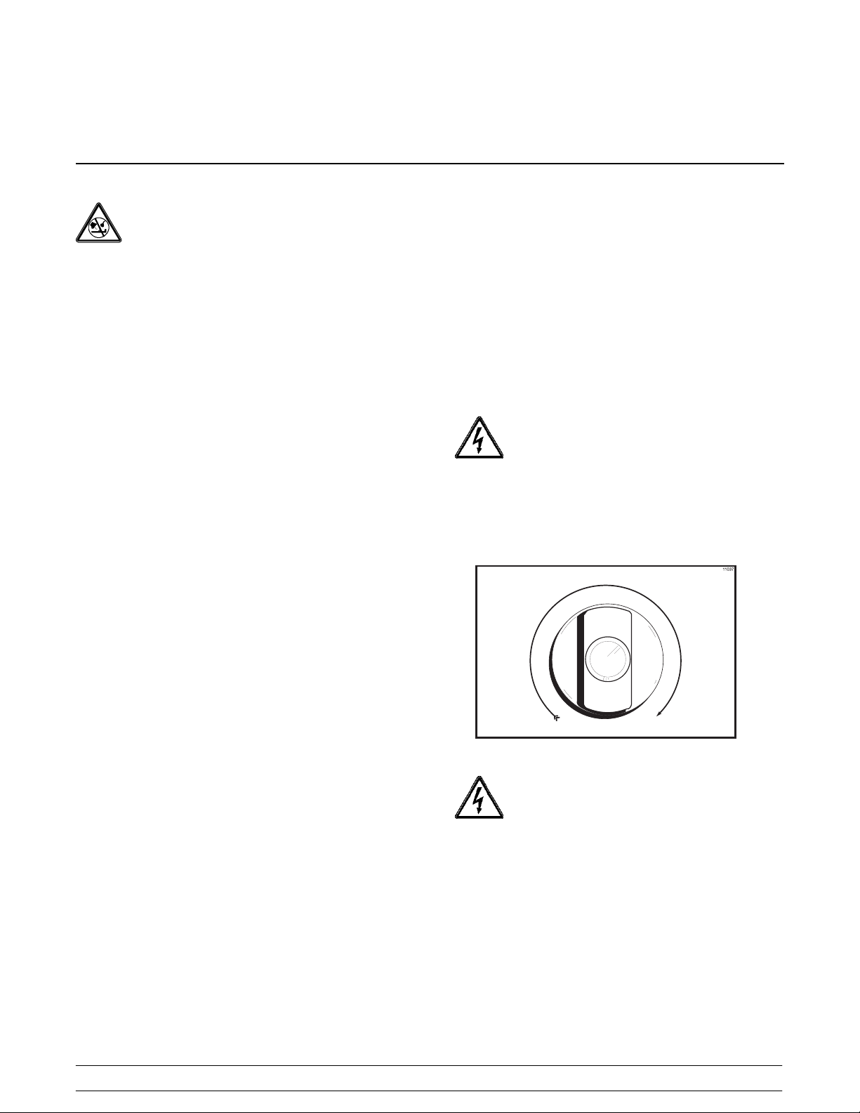
Adjustable Draw Handle 12...............................................
Operating Screen Descriptions 12..........................................
Operator Menu 15.......................................................
Section 6 Operating Procedures 18.....................................
Equipment Set Up 18.....................................................
Freezing Cylinder Assembly 18............................................
Mix Hopper Assembly 22.................................................
Sanitizing 25............................................................
Priming 27..............................................................
Daily Closing Procedures 27..............................................
Syrup Pump 29..........................................................
Daily Opening Procedures 34..............................................
Model PH85 Table of Contents
Page 4

Table of Contents -- Page 2
Manual Brush Cleaning 35................................................
Draining Product From T he Freezing Cylinder 35............................
Rinsing 36..............................................................
Cleaning and Sanitizing 37................................................
Disassembly 37..........................................................
Brush Cleaning 38.......................................................
Section 7 Important: Operator Checklist 40..............................
During Cleaning and Sanitizing 40.........................................
Troubleshooting Bacterial Count 40........................................
Regular Maintenance Checks 40...........................................
Winter Storage 41........................................................
Section 8 Troubleshooting Guide 42....................................
Section 9 Parts Replacement Schedule 48...............................
Section 10 Parts List 49.................................................
Wiring Diagrams 61......................................................
Note: Continuin g research results in steady improvements; therefore, information
in this manual is subject to change without notice.
Table of Contents Model PH85
Page 5
Section 1 To the Installer
This machine is designed for indoor use only.
DO NOT install the machine in an area where
a water jet could be used. Failure to follow this
instruction may result in serious electrical shock.
Water Connections
(Water Cooled Units Only)
An adequate cold water supply must be provided with
a hand shut-off valve. On the rear of the unit, two 1/2”
I.P.S. water connectionsfor inlet andoutlet have been
provided for easy hook-up. 1/2” inside diameter water
lines should be connected to the machine. (Flexible
lines are recommended, if local codes permit.)
Depending on local water conditions, it may be
advisable to install a water strainer to prevent foreign
substances from clogging the automatic water valve.
There will be only one water “in” and one water “out”
connection. DO NOT install a hand shut-off valve on
the water “out” line! Water should always flow in this
order:first,throughtheautomaticwatervalve;second,
through the condenser; and third, through the outlet
fitting to an opentrapdrain.
and property from hazards arising from the use of
electricity. This code contains provisions considered
necessary for safety . Compliance therewith and
proper maintenance will result in an installation
essentially free from hazard!
In all other areas of the world, equipment should be
installed in accordance with the existing local codes.
Please contact your local authorities.
Stationary appliances which are not equipped with a
power cord and a plug or other device to disconnect
the appliance from the power source must have an
all--pole disconnecting device with a contact gap of at
least 3 mm installed in the external installation.
CAUTION: THIS EQUIPMENT MUST BE
PROPERLY GROUNDED! FAILURE TO DO SO
CAN RESULT IN SEVERE PERSONAL INJURY
FROM ELECTRICAL SHOCK!
Beater rotation must be clockwise as viewed looking
into the freezing cylinder.
Air Cooled Units
Air cooled units require a minimum of 3” (76 mm) of
clearance around all sides of the freezer to allow for
adequate air flow across the condensers. A deflector
has been added to the underside, preventing
recirculation of warm air. Failure to allow adequate
clearance can reduce the refrigeration capacity of the
freezer and possibly cause permanent damage to the
compressors.
Electrical Connections
Each freezer requires one power supply. Check the
data label on the freezer for fuse, circuit ampacity and
electrical specifications. Refer to the wiring diagram
provided inside of the electrical box, for proper power
connections.
In the United States, this equipment is intended to be
installed in accordance with the National Electrical
Code (NEC), ANSI/NFPA 70--1987. The purpose of
the NECcode isthe practical safeguarding of persons
Figure 1
Note: The following procedures should be
performed by a trained service technician.
To correct rotation on a three-phase unit, interchange
any two incoming power supply lines at the freezer
main terminal block only .
To correct rotation on a single-phase unit, exchange
the leads inside thebeater motor. (Follow thediagram
printedonthemotor.)
Electrical connections are made directly to the
terminal block. The terminal block is provided in the
main control box located behind the service panel.
040419
Model PH85 To the Installer
1
Page 6

Section 2 To the Operator
The freezer you have purchased has been carefully
engineered and manufactured to give you dependable
operation. The Taylor Model PH85, when properly
operated and cared for, will produce a consistent
quality product. Like all mechanical products, this
machine will require cleaning and maintenance. A
minimum amount of care and attention is necessary if
the operating procedures outlined in this manual are
followed closely.
This Operator’s Manual should be read before
operating or performing any maintenance on your
equipment.
Your Model PH85 will NOT eventually compensate for
and correct any errors during the set-up or filling
operations. Thus, the initial assembly and priming
procedures are of extreme importance. It is strongly
recommended that personnel responsible for the
equipment’s operation, both assembly and
disassembly, study these procedures in order to be
properly trained and to make sure that no
misunderstandings exist.
In the event you should require technical assistance,
please contact your local authorized Taylor Distributor.
If the crossed out wheeled bin symbol is
affixed to this product, it signifies that this product is
compliant with the EU Directive as well as other similar
legislation in effect after August 13, 2005. Therefore,
it must be collected separately after its use is
completed, and cannot be disposed as unsorted
municipal waste.
The user is responsible for returning the product to the
appropriate collection facility, as specified by your local
code.
For additional information regarding applicable local
laws, please contact the municipal facility and/or local
distributor.
Compressor Warranty Disclaimer
The refrigeration compressor(s) on this machine are
warranted for the term indicated on the warranty card
accompanying this machine. However , due to the
Montreal Protocol and the U.S. Clean Air Act
Amendments of 1990, many new refrigerants are
being tested and developed, thus seeking their way
into the service industry. Some of these new
refrigerants are being advertised as drop-in
replacements for numerous applications. It should be
noted that, in the event of ordinary service to this
machine’s refrigeration system, only the refrigerant
specified on the affixed data label should be used.
The unauthorized use of alternate refrigerants will void
your compressor warranty . It will be the owner’s
responsibility to make this fact known to any technician
he employs.
It should also be noted that Taylor does not warrant the
refrigerant used in its equipment. For example, if the
refrigerant is lost during the course of ordinary service
to this machine, Taylor has no obligation to either
supply or provide its replacement either at billable or
unbillable terms. Taylor does have the obligation to
recommend a suitable replacement if the original
refrigerant is banned, obsoleted, or no longer available
during the five year warranty of the compressor.
The Taylor Company will continue to monitor the
industry and test new alternates as they are being
developed. Should a new alternate prove, through our
testing, that it would be accepted as a drop-in
replacement, then the above disclaimer would
become null and void. To find out the current status of
an alternate refrigerant as it relates to your
compressor warranty, call the local Taylor Distributor
or the Taylor Factory. Be prepared to provide the
Model/Serial Number of the unit in question.
050816
2
Model PH85To th e Operator
Page 7
Section 3 Safety
Weat TaylorCompanyare concernedabout thesafety
of the operator when he or she comes in contact with
the freezer and its parts. Taylor has gone to extreme
efforts to design and manufacture built-in safety
features to protectbothyouandtheservicetechnician.
As anexample, warning labels havebeen attached to
thefreezer to furtherpointoutsafetyprecautionstothe
operator.
IMPORTANT -- Failure to adhere to the
following safety precautions may result in severe
personal injury or death. Failure to comply with
these warnings may damage the machine and its
components. Component damage will result in
part replacement expense and service repair
expense.
S DO NOT allow untrained personnel to
operate this machine.
S DO NOT operate the freezer unless all
service panels and access doors are
restrained with screws.
S DO NOT remove the door, beater, scraper
blades, drive shaft or air/mix pump unless
the power switch is in the OFF position.
Failuretofollow theseinstructionsmayresult in severe
personal injury from hazardous moving parts.
To Operate Safely:
DO NOT operate the freezer without reading
this operator’smanual. Failuretofollow thisinstruction
may result in equipment damage, poor freezer
performance, health hazards, or personal injury.
S DO NOT operate the freezer unless it is
properly grounded.
S DO NOT operate the freezer with larger
fuses than specified on the freezer data
label.
S DO NOT attempt any repairs unless the
main power supply to the freezer has been
disconnected.
Failure to follow these instructions may result in
electrocution. Contact your local authorized T aylor
Distributor for service.
DO NOT use a water jet to clean or rinse the
freezer. Failure to follow this instruction may result in
serious electrical shock.
S DO NOT put objects or fingers in door
spout.
S USE EXTREME CAUTION when removing
the beater assembly.
Failure to follow these instructions may result in
contaminated product or personal injury from blade
contact.
DO NOT draw product duringthe HEATcycle
because of high product temperatures.
This freezer must be placed on a level
surface. Failureto comply mayresultin personal injury
or equipment damage.
DO NOT obstruct air intake and discharge openings:
3” (76 mm) minimum air space around all sides. A
deflector hasbeen added tothe underside,preventing
recirculation of warm air. Failure to follow this
instruction may cause poor freezer performance and
damage to the machine.
NOISE LEVEL: Airborne noise emission does not
exceed 78 dB(A) when measured at a distance of 1.0
meter from the surface of themachine and at a height
of 1.6 meters from the floor.
040423
Model PH85 Safety
3
Page 8
Section 4 Operator Parts Identification
4
Model PH85Operator Parts Identification
Page 9

PH85 Exploded View Parts Identification
2
5
ITEM DESCRIPTION PART NO.
1 COVER A.-HOPPER 053809
2 AGITATOR A. - HOPPER X44797
3 PAN-DRIP HT 048204
4 PANEL-REAR *8784 AIR* 048212
5 LOUVER-SIDE-RIGHT 017471
6 PANEL-UPPER SIDE R. *754-5* 028823
7 TRIM-REAR CORNER RIGHT 042695
*7 TRIM-REAR CORNER LEFT 042697
8 PANEL A.-SIDE LOWER R X46448-SER
9 PIN-RETAINING-HOPPER CVR 043934
10 CASTER-SWV 5/8 STEM 4”
WHEEL
11 SCREW-1/4-20X3/8 RHM 011694
12 TRAY-DRIP *8662-8663* 028542
13 SHIELD-SPLASH 028548
14 DISPLAY-LIQUID CRYSTAL X38062-SER
15 DECAL-DEC-TAYLOR PH85 052283
16 PANEL A. -FRONT *8784* X45253
17 STUD-NOSE CONE 022822
018794
ITEM DESCRIPTION PART NO.
18 PAN-DRIP 17-1/4”LONG 027504
19 JAR-SYRUP PLASTIC 036573
20 LID-SYRUP JAR 042706
21 LADLE-1 OZ 033637-1
22 LOUVER-SIDE-LEFT 028288
23 PANEL-UPPER SIDE L. *754-5* 028822
24 PANEL A. -SIDE LOWER L X46447-SER
PUMP A.-SYRUP-HEATEDBRN
25
PUMP A.-SYRUP-HEATED-TAN X53800 -TAN
26 PANEL-SERVICE *8784* 045071
27 GUIDE A.-DRIP PAN-MIX
PUMP
28 ADAPTOR A. -CASTER X18915
29 JAR-SYRUP*STAINLESS 036574
* BUSHING-PANEL 013289
* ANGLE-PANEL-LEFT *774* 042578
* ANGLE-PANEL-RIGHT *774* 042579
* GUIDE A.-DRIP PAN
*339-8754*
* PLUG-DRIP TRAY HOLE 029595
*NOT SHOWN
X53800-BRN
X48228
X28699
Model PH85 Operator Parts Identification
5
Page 10
Beater Door Assembly
ITEM DESCRIPTION PART NO.
1 SEAL-DRIVE SHAFT 032560
2 SHAFT-BEATER 032564
3 BEATER ASSEMBLY X46231
4 CLIP-SCRAPER·BLADE 046236
5 BLADE-SCRAPER 046235
6 KIT A. -BEATER-FRONT SHOES X50350
6a SHOE--FRONT HEL IX 050346
6b BEARING--FRONT 050348
6c SHOE--FRONT HELIX 050347
7 GASKET-DOOR HT 4”-DBL 048926
8 DOOR-3 SPT X51532-11
9 HANDLE A.-DRAW-ADJ. X33687
9a HANDLE-ADJUSTABLE 028804
ITEM DESCRIPTION PART NO.
9b SCREW-ADJUST.-5/16-24X1-1 033662
9c O -RING-1/4 OD X .070W 50 015872
9d NUT-JAM 029639-BLK
10 O-RING-5/16 OD X .070W 016272
11 ROD A. -PIVOT X20683
12 NUT-STUD LONG 034382
13 VALVE A. -DRAW SELF CLEAN X33582
14 O-RING-7/8 OD X .103W 014402
15 CAP-DESIGN-1.010”ID-6 POINT 014218
16 NUT-STUD SHORT 034383
17 VALVE A. -DRAW CENTER X37376
18 SEAL-DRAW VALVE 034698
6
Model PH85Operator Parts Identification
Page 11

Air/Mix Pump
ITEM DESCRIPTION PART NO.
1--13 Pump A.-Coax-Soft Serve X45316--B
1 Mix Inlet Tube A. X45318
2 Seal-Air Inlet Fitting 045327
3 O-Ring-Mix Inlet Fitting 015835
4 Spring 022456
5 Rubber Poppet 022473
6 Valve Body A.-SoftServe X46860--B
7 O-Ring2-1/8 OD 020051
8 O-Ring1-3/8 OD 018664
9 Check Band-ValveBody 020050
10 Check Band-Valve Body 033215
11 Piston-Pump-- Soft Serve 045319--B
ITEM DESCRIPTION PART NO.
12 Pin A.--Coax Pump X36950
13 Pump Cylinder-SoftServe X44755
14 Clip--Mix Pump Retainer 044641
15 O--Ring 1--3/4 008904
16 Shaft--Drive 041948
17 Crank--Drive 039235
18 O--Ring--Drive Shaft 048632
19 Pin--Cotter--Hairpin 044731
20 O-Ring-Mix Feed Tube 016132
21 TubeA.-- Feed--HPR--SS Right X44664
22 TubeA.-- Feed--HPR--SS Left X44662
Model PH85 Operator Parts Identification
7
Page 12
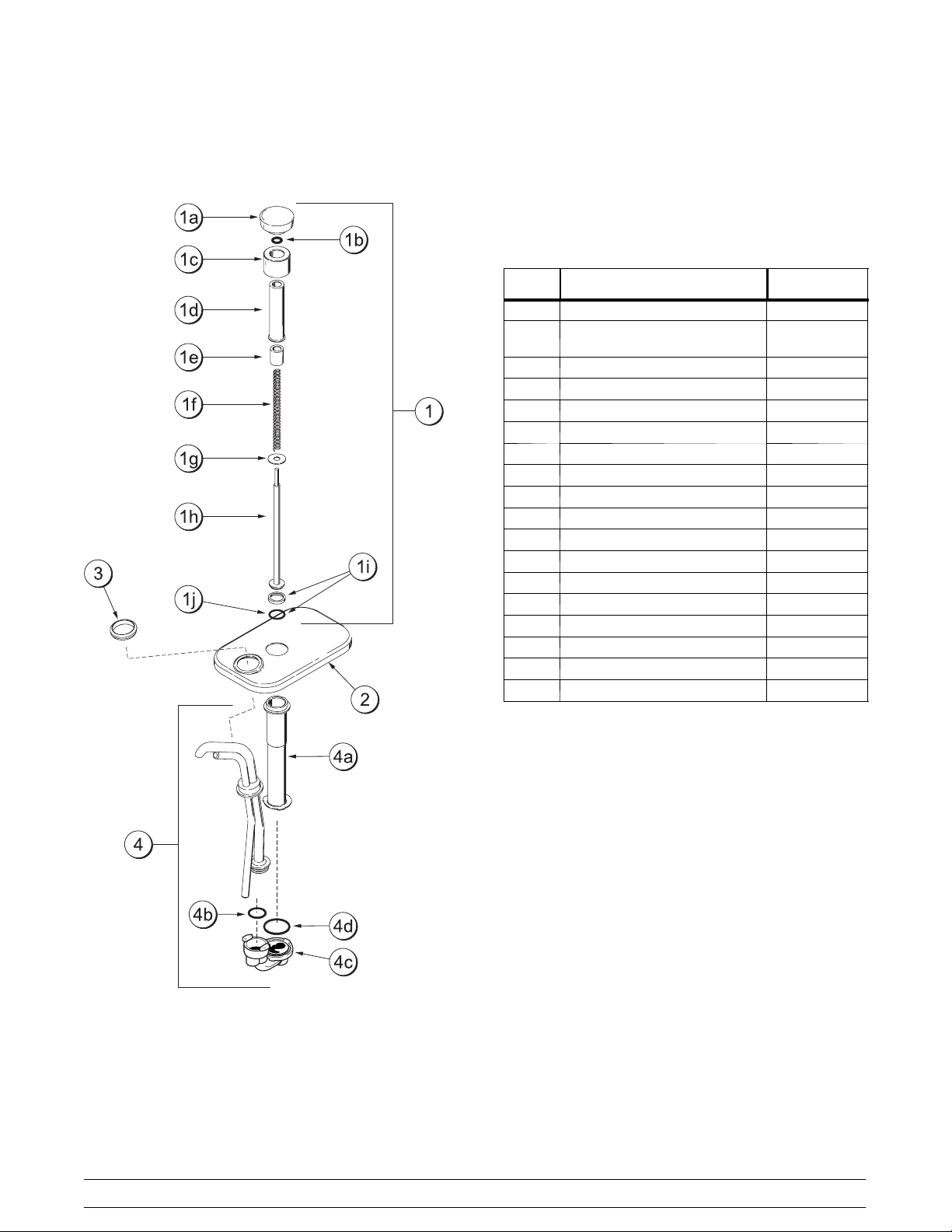
Syrup Pump
ITEM DESCRIPTION PART NO.
1 Plunger A. X36576--
1a Knob-Plunger 032762-TAN
032762--BRN
1b O-Ring-Knob 016369
1c Nut-Plunger 036577
1d Tube-Plunger 032757
1e Insert-Plunger 032758
1f Spring-Plunger-SyrupPump 032761
1g Washer-Nylon 032760
1h Plunger 036578
1i Seal Assembly X33057
1j O-Ring- Plunger 019330
2 Lid-Pump 036579
3 Nut-Spout 039680
4 Pump A.--Syrup Heated X50963 --SER
4a Cylinder--Syrup Pump 051065
4b O-Ring-OutletTube 048148
4d O-Ring-Plunger Tube 048149
4c Body-Valve - SyrupPump 048166
8
Model PH85Operator Parts Identification
Page 13
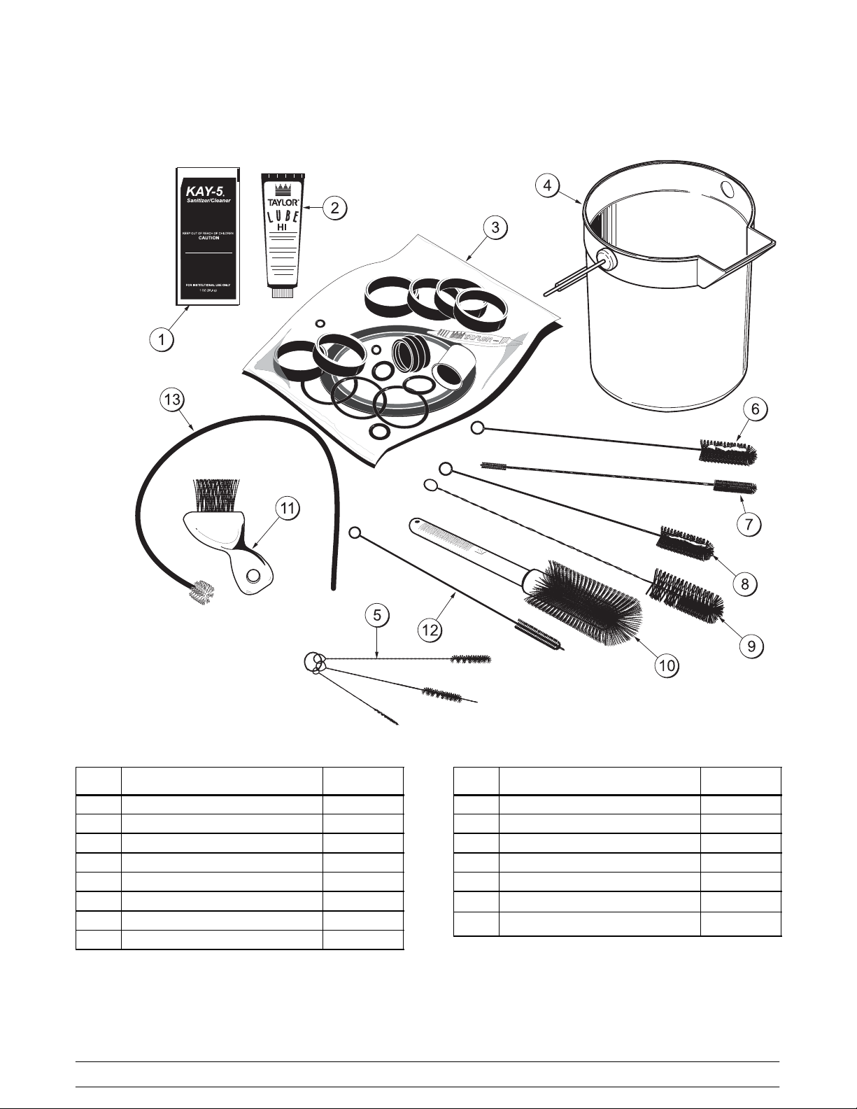
Accessories
ITEM DESCRIPTION PART NO.
1 SANITIZER KAY-5 (125 PACKS) 041082
2 LUBRICANT-TAYLOR HI-PERF. 048232
3 KIT - TUNE UP X49463-1
4 PAIL-MIX 10 QT. 013163
5 BRUSH-SET LVB 050103
6 BRUSH-REAR BRG 1 IN.DX2 IN 013071
7 BRUSH-DOUBLE ENDED 013072
8 BRUSH-DRAW VALVE 1”ODX2” 013073
Model PH85 Operator Parts Identification
ITEM DESCRIPTION PART NO.
9 BRUSH-DRAW VALVE 1-1/2”OD 014753
10 BRUSH-MIX PUMP BODY-3”X7” 023316
11 BRUSH-END-DOOR-SPOUT-SS 039719
12 BRUSH-1/2 IN. DIA. 033059
13 BRUSH-PUMP SPOUT 054068
* CHART-BRUSH KIT-HT 044127
*
SANTIZER-STERA-SHEEN
*NOT SHOWN
9
010425
Page 14
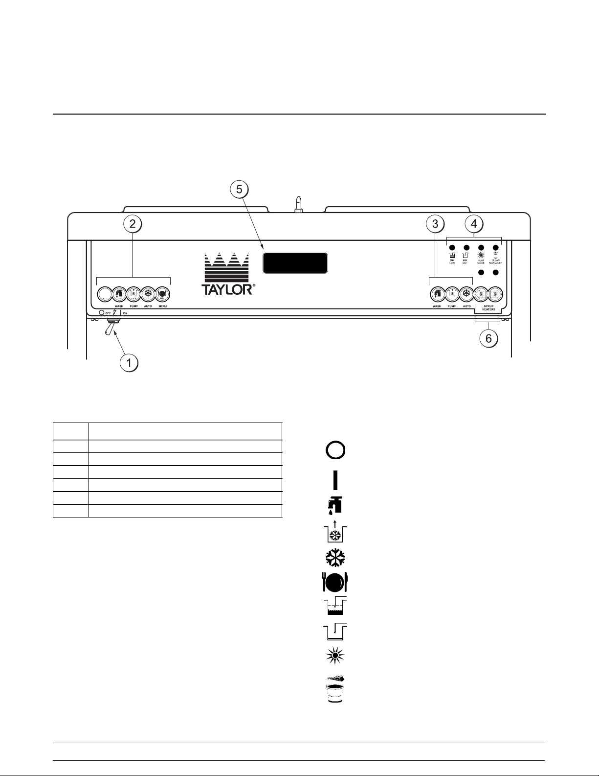
Section 5 Important: To the Operator
ITEM DESCRIPTION
1 POWER SWITCH
2 KEYS -- LEFT SIDE
3 KEYS -- RIGHT SIDE
4 INDICA T OR LIGHTS
5 LIQUID CRYSTAL DISPLAY
6 KEYS -- SYRUP HEATERS
Symbol Definitions
To better communicate in the International arena, the
words on many of our operator switches and buttons
have symbols to indicate their functions. Your Taylor
equipment is designed with these International
symbols.
The following chart identifies the symbol definitions.
=OFF
=ON
= WASH
=PUMP
=AUTO
=MENU
=MIXLOW
= MIX OUT
= HEAT MODE, SYRUP HEATERS
= CLEAN MANUALLY/BRUSH CLEAN
10
Model PH85Important: To the Operator
Page 15

Power Switch
Thepower switchis locatedunder the control panel on
the left hand side of the unit. When placed in the ON
position, the power switch allows Softech panel
operation.
Indicator Lights
Mix Low - When the MIX LOW light begins to flash, it
indicates the mix hopper has a low supply of mix and
should be refilled as soon as possible. The word
“LOW” will also display on theLCD indicatornextto the
word “MIX”.
Liquid Crystal Display
TheLiquidCrystal Display (LCD) islocated on thefront
control panel. The LCD is usedto show in what mode
the freezer is operating and whether or not there is
sufficient mix.
Reset Mechanism
Mix Out - When the MIX OUT light begins to flash, it
indicates the mix hopper has been almost completely
exhausted and has an insufficient supply of mix to
operate the freezer. The word “OUT” will also display
on the LCD indicator next to the word “MIX”. At this
time the AUTO mode is lockedout andthe freezer will
be placed in the STANDBY mode. To initiate the
refrigeration system, add mix to the mix hopper and
press the AUTO key. The freezer will automatically
begin operation.
Heat Mode - When the HEAT MODE light isflashing,
it indicates that the freezer is in the process of a heat
cycle.
Clean Manually -When theCLEAN MANUALLYlight
is flashing, it indicates that the machine must be
disassembled and brush cleaned within 24 hours.
When all four indicatorlights areflashing, thissignifies
a locked condition. When MIX LOW and MIX OUT
lights are flashing only, this signifies an unlocked
condition.
Syrup Heaters -- Indicatorlightsare located abovethe
LEFTandRIGHTkeys.Pressthe LEFTkeytoactivate
the heater for the left side of the syrup rail. Press the
RIGHT key to activate the heater for the right side of
the syrup rail.
The reset buttons are located in the center of the
servicepanel. Thereisone foreach sideof thefreezer.
The reset mechanism protects the beater motor from
an overload condition. Ifan overload occurs, thereset
mechanism will trip. To properly reset the freezer,
place the powerswitch inthe OFF position. Press the
reset button firmly. Turn the power switch to the ON
position. Clear the fault. Press the WASH key and
observe the freezer’s performance. Open the side
access panel tocheck if thebeater motoris turningthe
drive shaft in a clockwise direction (from the operator
end) without binding.
Donot usemetal objectsto press thereset
button. Failure to follow this instruction may
result in electrocution.
If the beater is turning properly, press the WASH key
to cancelthe cycle. PresstheAUTOkey on bothsides
of the machine to resume normal operation. If the
freezer shuts down again, contact a service
technician.
Model PH85 Important: To the Operator
11
Page 16
Adjustable Draw Handle
Thisunitfeaturesan adjustabledrawhandletoprovide
the best portion control, giving a better, consistent
quality toyour product and controllingcosts.The draw
handle should be adjusted to provide a flow rate of 5
to 7-1/2 oz. of product by weight per 10 seconds. To
INCREASE the flow rate, turn the screw
COUNTERCLOCKWISE, and CLOCKWISE to
DECREASE theflow rate. In addition, for purposes of
SANITIZING and RINSING, the flow rate can be
increased by removing the pivot pin and placing the
restrictive bar on the TOP. When drawing product,
always have the restrictive bar on the BOTTOM.
IMPORTANT: Once the draw rate is set,
tighten the lock nut with a wrench.
Operating Screen Descriptions
Whenthemachineispoweredthesystem willinitialize.
The screen will display “INITIALIZING”. There will be
four typesof data the system will check: LANGUAGE,
SYSTEM DATA, CONFIG DATA, and LOCKOUT
DATA. During the INITIALIZING... LANGUAGE
screen, the alarm will be on. If the system data,
configuration data,orlockout history data hasbecome
corrupt, thefollowing screenwill alertthe operatorthat
the system settings may have been changed.
NVRAM FAULT
RESET TODEFAULTS
PRESS SEL KEY
Once the system has initialized the SAFETY
TIMEOUT screen is displayedand thealarm is turned
on.
After the safety timeout has been completed, and the
power switch is OFF, one of the following screens is
displayed.
The first screen is displayed if the machine is not in a
brush clean state. If any of the requirements for a
brush cleanhave notbeen met, the time displayedwill
remain at 5:00 minutes. When all the requirements for
a brush cleaning are met, andthe five minutes expire,
the screen will change to the second screen, which is
the standard power switch OFF screen.
POWER SWITCH OFF
OUT TIME: 4:40 OUT
68.5 HOPPER 62.1
69.5 BARREL 67.7
POWER SWITCH OFF
-- = -- = -- = -- = -- = -UNIT CLEANED
When the power switch is set in the ON position, the
system mode of operation screen is displayed. In this
example, themachineis ON,but no mode ofoperation
has been selected. The second line of the display
indicates whether there is a sufficient supply of mix in
the hopper or if there is a LOW or OUT mix condition.
The third line of the display shows the temperature of
the mix hopper. After pressing the AUTO key, the last
line of the display shows the month and date (MM =
month, DD = day) that the machine needs to be
disassembled and brush cleaned.
SAFETY TIMEOUT
ANY KEY ABORTS
This screenwill bedisplayed, withthe alarm on, for 60
seconds or until any key is pressed.
12
OFF :MODE: OFF
OK :MIX: OK
40.0F HOPPER 40.0F
BRUSH CLEAN ON: MM/DD
Model PH85Important: To the Operator
Page 17

This display indicates the freezer is operating in 3
different modes. The following information is given:
The left side of the freezer is operating in the
STANDBY mode, and the mix level in the hopper is
OUT. The right side is operating in the WASH and
PUMP modes,and themix level inthe hopper isLOW.
The temperature of the mix in both hoppers is 40_F.
(4.4_C.), and the machine needs to be brushcleaned
on October 31st.
STANDBY :MODE: WSH--PMP
OUT :MIX: LOW
40.0F HOPPER 40.0F
BRUSH CLEAN ON: 10/31
The following displays pertain to the HEAT cycle:
While inthe heating phase, you will see this display.It
shows the present temperature of the hopper.
HEAT :MODE: HEAT
HEAT :PHASE: HEAT
140.0F HOPPER 140.0F
BRUSH CLEAN ON: MM/DD
The final phase of the heat treatment cycle is the
cooling phase. Now the freezer must cool the mix
below 41_F. (5_C.). If the product fails to cool in 2
hours, the freezer will lock out.
This example illustrates that the temperature is being
lowered, but has not yet reached the set point.
HEAT :MODE: HEAT
COOL :PHASE: COOL
55.0F HOPPER 55.0F
BRUSH CLEAN ON: MM/DD
When the entire heat cycle has been completed, the
normaldisplay willappear, showing themachine inthe
STANDBY mode. The machine may now be placed in
AUTO or left in STANDBY.
STANDBY :MODE: STANDBY
OK :MIX: OK
41.0F HOPPER 41.0F
BRUSH CLEAN ON: MM/DD
Hard Lock: There are two causes for a hard lock:
The mix temperature must be raised above 151_F.
(66.1_C.) within 90 minutes or the freezer will be
locked in STANDBY, and the cycle failure display will
appear.
In the example, the hopper temperature is 140_F.
(60_C.). The phase shows that the machine is in the
HEAT phase of the treatment cycle.
When theheating phaseis complete,the freezer goes
into the holding phase of the cycle.The holding phase
will hold the temperature above151_F.(66.1_C.) for a
minimum of 30 minutes.
In this example, the hopper temperature is 151_F.
(66.1_C.).
HEAT :MODE: HEAT
HOLD :PHASE: HOLD
151.0F HOPPER 151.0F
BRUSH CLEAN ON: MM/DD
1. Fourteen days have elapsed since the last
brush cleaning. The following screen will be
displayed.
14 DAY TIMEOUT
CLEANING REQ’D
FREEZER LOCKED
PRESS SEL KEY
2. There has been a thermistor failure (freezing
cylinder, hopper, or glycol) during the heat
treatment process.
SYSTEM FAULT
SERVICE REQ’D
FREEZER LOCKED
PRESS SEL KEY
All four LED’s on the front of the freezer will flash.
Press the SEL key.
Model PH85 Important: To the Operator
13
Page 18

The next display is the screen which will appear after
thefailuremessage. Tocomply withhealth codes,heat
treatment system freezers must complete a heat
treatment cycle daily, and must also be brushed
cleaned every 14 days. Brush cleaning is the normal
disassembly andcleaning procedure. Failure tofollow
these guidelines will cause the control to lock the
freezer out of the AUTO mode. Press the WASH key.
NO AUTO OPERATION
ALLOWED UNTIL
BRUSH CLEANING
PRESS WASH KEY
The next display is the screen which will appear after
the brush cleaning message and illustrates that the
control is in the OFF mode and the machine needs to
be disassembled and brush cleaned.
Once the unitisunlocked, onlythe mix outand mix low
LED’s will flash.
OFF :MODE: OFF
OK :MIX: OK
41.0F HOPPER 41.0F
FREEZER LOCKED
NO HEAT TREAT START
BECAUSE
VARIABLE MESSAGE
PRESS SEL KEY
If the following screen appears, a soft lock has
occurred during the heat treatment cycle.
HEAT TREAT CYCLE
FAILURE
FREEZER LOCKED
PRESS SEL KEY
If the temperature of the product has not fallen below
41_F(5_C)bytheendoftheCOOLcycle,thefollowing
screen will appear.
PRODUCT OVER TEMP
FREEZER LOCKED
PRESS SEL KEY
Soft Lock: If a heat treatment cycle has not been
initiatedwithin the last 24 hours, all four LED’son the
front of the machine will flash and a message will
appear onthe LCD. Line 3 of the LCDwill indicate the
reason the message appears. Following are the
variable messages which will appear on line 3:
1. POWER SWITCH OFF: Power switch was in
the OFF position.
2. MIX OUT PRESENT: There was mix out
condition present.
3. AUTO OR STANDBY OFF: The unit was not in
the AUTO or STANDBY mode.
4. NO HEAT CYCLE TRIED: A heat treatment
cycle was not attempted in the last 24 hours.
(AUTO HEAT TIME was advanced, or a power
loss was experienced at the time the cycle was
to occur, or a heat cycle failure not due to a
thermistor failure.)
Press the SEL key to advance to the next display.
When one of these messages appears, automatic
freezer operation cannot take place untilthe freezer is
disassembled and brush cleaned or has completed a
heat treatment cycle. Thenext display willinstruct the
operator to start a heat treatment cycle manually (by
pressing the AUTOkey),or to disassemble and brush
clean the freezer. If the AUTO key is pressed, the
freezerwill automaticallystarttheheat treatmentcycle
and only the heat cycle LED will flash.
NO AUTO OPERATION
ALLOWED. PRESS
AUTO FOR HEAT CYCLE
WASH TO BRUSH CLEAN
14
Model PH85Important: To the Operator
Page 19

If the WASH key is pressed, the next display will
appear and the freezer will have to be disassembled
and brush cleaned.
3. HPCO COMPRESSOR: Place the power
switch in the OFF position. Wait 5 minutes for
the machine to cool. Place the power switch in
the ON position. Clear the tone.
OFF :MODE: OFF
OK :MIX: OK
41.0F HOPPER 41.0F
FREEZER LOCKED
Once the freezer is unlocked by starting a heat
treatment cycle, only the heat cycle LED will flash. If
the freezer is unlocked by brush cleaning, the mix low
and mix out LED’s will flash.
Operator Menu
The OPERATOR MENU isused to enter the operator
function displays. To access the OPERATOR MENU,
simply press theMENU key.The cursor will flash over
theletter“A” indicatingthat this isscreen “A”. Toselect
a different screen, use the arrow keys and move the
cursor to the desired screen selection and press the
SEL key.
OPERATOR MENU
BCDEFGHIJ
A
EXIT FROM MENU
<--- ---> SEL
4. COMP ON TOO LONG: Place the power
switch in the OFF position. Call a service
technician. Clear the tone.
5. HOPPER THERM BAD: Place the power
switch in the OFF position. Call a service
technician.
6. BARREL THERM BAD: Place the power switch
in the OFF position. Call a service technician.
7. GLYCOL THERM BAD: Place the power switch
in the OFF position. Call a service technician.
8. HOPPER OVER TEMP: The hopper
temperature has risen too high as follows. Clear
the tone.
a. The hopper temperature reaches 41_F.
(5_C.) or higher after a power failure.
b. Thehoppertemperaturehasnot fallenbelow
41_F. (5_C.) by the end of the COOL phase
in the heat cycle.
9. BARREL OVER TEMP: The barrel (freezing
cylinder) temperature has risen too high as
follows. Clear the tone.
a. The barrel (freezing cylinder) temperature
Screen “B” is FAULT DESCRIPTION. The fault
description will indicate if there is a fault with the
reaches 41_F. (5_C.) or higherafter a power
failure.
freezer and the side of the freezer where the fault
occurred. To clear the tone for any faults which have
beencorrected,press theleft arrowkey.Tosee if there
is morethan one fault per cylinder,press the SELkey.
b. The barrel (freezing cylinder) temperature
has not fallen below 41_F. (5_C.) by the end
of the COOL phase in the heat cycle.
When the last fault is displayed, the control will return
to the OPERATOR MENU. To return to the main
screen, move the cursor to “A” and press the SELkey
again. Listed below are the variable messages which
10. POWER FAILURE: This message will appear in
the FAULT DESCRIPTION if a power failure
has occurred. Clear the tone.
will appear, along with the corrective action:
1. NO FAULT FOUND: There was no fault found
in the freezer. Nothing will appear on the screen
after this variable message appears.
2. BEATER OVERLOAD: Press the reset button
FAULT DESCRIPTION
L: VARIABLE MESSAGE
R: VARIABLE MESSAGE
CLR SEL
firmly. Clear the tone.
Model PH85 Important: To the Operator
15
Page 20

Screen “C” isSET CLOCK.Thisscreen will displaythe
current date and time. The date and time may be
changed only after the freezer has been manually
brush cleaned, but before it has been placed in the
AUTO mode. Move the cursor under the number you
wish to change. Press the plus key to increase the
number; pressthe minus key to decreasethe number .
When the desired time and date appears, press the
SEL key once to return to the OPERAT OR MENU.
SET CLOCK
10:21 AM 11/07/1999
-- -<--- ---> +++ ------ SEL
If an illegal date is entered, the following screen will
appear. The correct date must be entered before
leaving this display.
SET CLOCK
10:34 AM 02/30/1999
INVALID DATE
SEL
Screen “D” is SYSTEM INFORMATION. The first
screen will indicate the software version used in the
unit.
SOFTWARE VERSION
PH85 Control UVC2
Version 2.00
SEL
Press the SEL key to view the second screen of the
SYSTEM INFORMATION display. This screen will
indicate theBill ofMaterial number and Serial Number
for the unit. Press the SEL key once to return to the
Operator Menu.
B.O.M. PH8533B000
S/N J0000000
Screen “E” is AUTO HEAT TIME. This screen is used
to set the timeof dayinwhich theheat treatment cycle
will start. Move the cursor under the number you wish
to change.Press the plus key toincrease the number;
press the minus key to decrease the number. When
the desired time appears, press the SEL key once to
return to the OPERATOR MENU.
AUTO HEAT TIME
TIME: 12:00 AM
-- --
<--- ---> +++ ------ SEL
Screen “F” is CURRENT CONDITIONS. This screen
gives the viscosity of the product and the hopper and
barrel temperatures. The last line of the display is the
compressor countdown safety timer. The safety timer
prevents the compressor from running more than 11
minutes (other than during the cooling phase of the
heat treatment cycle).
VISC HOPPER BARREL
0 38.5 28.5
0.0 38.5 18.0
TIME C 11:00 11:00
Press the SEL key once to view the SERVINGS
COUNTER screen.
The SERVINGS COUNTER screen indicates the
number of times the draw switch has closed (number
ofdraws) sincethe last brushcleaning or sincethelast
serving counter reset. A maximum of 32,767 draws
can be recorded; an additional draw will cause the
counter to restart at zero. Pressing the SEL key will
return the display to the Operator Menu.
SERVINGS COUNTER
LEFT RIGHT
12 15
SEL
SEL
Draws are counted during the AUTO mode of
operation only.
16
Model PH85Important: To the Operator
Page 21

Screen “G” is HEAT CYCLE DATA. The information
from the previous heat treatment cycles can be
obtained through this screen. The most recent heat
treatment cycledata willbe shown first; press the plus
keytoscrollthroughthe remainingheat cycledisplays.
If a heat treatment cycle failure should occur, a 2
character message will appear on the second line of
the screen. Press the SEL key once to return to the
OPERATOR MENU.
Listed below are the variable messages which could
appear:
HT Failure in the heating phase.
CL Failure in the cooling phase.
TT Failure in meeting total heat treatment cycle
time requirement.
MO Mix out condition.
OP Operator interruption.
PF Power failure. (If a power failure occurs, but
the heat treatment cycle does not fail, an
asterisk (*) will appear on the third line of the
display.)
BO Beater overload.
HO High pressure cut-out.
TH Failed thermistor probe.
PS Power switch placed in the OFF position.
ML Mix Low Condition.
14 14 Day Timeout Occurred.
RC Heat Cycle Record Cleared.
11/07 02:00 05:09
HEAT OVER COOL XX
01:09 00:45 01:14
TEMP AT END 38.5 1
Pressingtheleft arrowkey on any HEATCYCLEDATA
screen will cause the extended data screen to be
displayed. This screen shows the hopper, barrel, and
glycol temperatures, and the amount of time the
freezer spentin thephases of theheat cycle when the
heat cycle completed, or was terminated.
Screen “H” is the LOCKOUT HISTORY. This screen
displays a history of the last 40 hard locks, soft locks,
and brush clean dates.Page numbers are indicated in
the upper right hand corner. Page 1 always contains
the most recent failure. Press the PUMP key to cycle
through the pages.
The second line of the screen displays the date and
time a failure occurs. The third line indicates the
reason for a failure, or will indicate a successful brush
cleaning has occurred. Some failures occur for
multiple reasons. When this occurs, a page will be
generated for eachreason. Press theSEL key onceto
return to the Operator Menu.
LOCKOUT HISTORY 1
11/21/99 02:08
SOFTLOCK ABORT
+ + + -- -- -- S E L
Screen “I” is the SERVICE MENU. This screen can
only be accessed by a service technician.
Screen “J” is the STANDBY MODE. To place the left
side of the freezer in the STANDBY mode, move the
cursor under the word “yes”. Press the SEL key to
execute the command and bring up the screen for the
right side of the freezer. To place the right side of the
freezer in theSTANDBYmode, movethe cursorunder
the word “yes”. When the SEL key is pressed, the
command will be executed. To exit the STANDBY
modeand place theunitinAUTO, presstheAUTO key
once. Pressing the AUTO key again willplace the unit
in the OFF mode.
STANDBY MODE
LEFT YES NO
-- -- --
<--- ---> SEL
HOPPER BARREL GLYCOL
151.0 134.5 98.1
153.0 136.0
PHASE TIME:1:20 1
Model PH85 Important: To the Operator
17
Page 22

Section 6 Operating Procedures
Equipment Set Up
Evaluate the condition of lights and screen messages
(Hard Lock or Soft Lock, etc.) before performing
openingprocedures. Ifall fourLED’sonthe frontof the
unit are lit, the unit is locked. (See Figure 2.)
Figure 3
Insert the drive shaft through the rear shell bearing in
the freezing cylinder and engage the hex end firmly
into the drive coupling. (See Figure 4.)
Figure 2
Freezing Cylinder Assembly
MAKE SURE POWER SWITCH IS IN THE
“OFF” POSITION. Failure to do so may cause injury
from hazardous moving parts, or electrocution.
Step 1
Before installing the drive shaft, lubricate the groove
on the drive shaft. Slide the drive shaft seal over the
small end of the shaft and engage into the groove on
the shaft. Heavily lubricate the inside portion of the
seal and also lubricate the flat end of the seal that
comes in contact with the rear shell bearing. Apply an
even coat of lubricant to the shaft. DO NOT lubricate
the hex end. (See Figure 3.)
Note: When lubricating parts, use an approved food
grade lubricant (example: Taylor Lube Hi
Performance).
Figure 4
Step 2
Install the beater assembly . First check the scraper
blades for any nicks or signs of wear. If any nicks are
present, replace the blades.
Note: Scraper blades should be replaced every 3
months.
18
Model PH85Operating Procedures
Page 23

Ifbladesareingoodcondition, installthescraperblade
clips on the scraper blades. Place the rear scraper
bladeovertherear holding pin onthe beaterassembly.
(See Figure 5.)
Figure 5
Note: Thehole on the scraperblade must fit securely
over the pin to prevent costly damage.
Holding the rear blade on the beater, slide the beater
assembly into the freezing cylinder until the entire
blade is inside. Install the front scraper blade over the
front holding pinand slidethebeaterassembly therest
of the way into the freezing cylinder. (See Figure 7.)
Figure 7
Rotate andinsert thebeater assembly inposition over
the drive shaft. When properly seated over the drive
shaft, thebeater assemblywillnotprotrudebeyond the
front of the freezing cylinder.
Repeat steps 1 and 2 for the other side of the
freezer.
Install the beater shoes.
Figure 6
Step 3
Assemblethefreezerdoor.Place the door gasketsinto
the grooves on the back of the freezer door. Slide the
front bearingsover the baffle rods so the flangededge
is against the door. DO NOT lubricate the gaskets or
bearings. (See Figure 8.)
Figure 8
Model PH85 Operating Procedures
19
Page 24

Step 4
Install the freezer door. Insert the baffle rods through
the beaters in the freezing cylinders. With the door
seated on the freezer studs, install the handscrews.
Tighten equally in a criss-cross pattern to insure the
door is snug. (See Figure 9.)
Figure 9
Lubricate theinsideof thefreezer door spouts,top and
bottom. (See Figure 11.)
Figure 11
Insert the draw valves from the bottom until the slot in
the draw valve comes into view. (See Figure 12.)
Step 5
Install the draw valves. Slide the 3 o-rings into the
grooves on each draw valve and lubricate. (See
Figure 10.)
Figure 10
Figure 12
Step 6
Slide the o-ring into the groove on the pivot pin and
lubricate. (See Figure 13.)
Thecenter drawvalve uses asealandano--ring. Slide
the seal and o--ring into their respective grooves and
lubricate.
20
Figure 13
Model PH85Operating Procedures
Page 25

Install the draw handles. Slide the fork of the draw
handle in the slot of the draw valve, starting from the
right. Slidetheshort pivotpinthrough thefar rightdraw
handle. Slidethe long pivot pin through the far left and
middle draw handles. (See Figure 14.)
Figure 14
Note: Thisunit features anadjustable drawhandle to
provide portion control, giving a better consistent
quality toyour product and controllingcosts.The draw
handle should be adjusted to provide a flow rate of 5
to 7-1/2 oz. (142 g. to 213g.) of product by weight per
10 seconds. To INCREASE the flow rate, turn the
adjustment screw COUNTER--CLOCK WISE and
CLOCKWISE to DECREASE the flow rate.
IMPORTANT: Once the draw rate is set,
tighten the lock nut with a wrench.
Step 7
Snap the design caps over the bottom of the door
spouts. (See Figure 15.)
Step 8
Slide the long drip pan into the hole in the side panel.
(See Figure 16.)
Figure 16
Slidethe twoshorterdrippans intothe holesin therear
panel.
Step 9
Install the front drip tray and splash shield under the
door spouts. (See Figure 17.)
Figure 15
Model PH85 Operating Procedures
21
Figure 17
Page 26

Mix Hopper Assembly
Step 1
Inspect the rubber pump parts. Check bands and
o-rings must be in 100% good condition for the pump
and entire unit to operate properly. Check bands and
o-rings cannot properly serve their intended functions
if nicks,cuts, orholes inthe materialare present. The
rubber poppet must also be in good condition.
Refer to page 48 for the normal replacement
schedule. Replace any defective parts immediately
and discard the old.
Step 2
Assemble the piston. Slide the o-ring into the groove
of the piston. DO NOT lubricate this o-ring. (See
Figure 18.)
Note: Check bands have two smooth surfaces. A
concave shape indicates an incorrect assembly. Turn
the check band inside out to correctly expose the flat
surface. (See Figure 20.)
Figure 20
Step 4
Lightly lubricate the inside wall of the piston with a
paper thin layer of lubricant (example: Taylor Lube Hi
Performance). See Figure 21.)
Figure 18
Step 3
Assemble the valve body. Slide two large and one
small o-ring, and two large and one small check band
into their respective grooves on the valve body. (See
Figure 19.)
Figure 19
Figure 21
Insert the narrow end of the valve body into the open
end of the piston. (See Figure 22.)
Figure 22
22
Model PH85Operating Procedures
Page 27

Step 5
Lightly lubricate the inside of the pump cylinder at the
bottom with a paper thin layer of lubricant. (See
Figure 23.)
Step 6
Assemble themix inlettube assembly.Slide theo-ring
andseal into thegrooveson thefittingsandthoroughly
lubricate. (See Figure 25.)
Figure 23
Insert the already assembled piston and valve body
into the bottom of the pump cylinder. (See Figure 24.)
Figure 24
Note: The drive hole in the piston must be visible
through the drive hole opening in the pump cylinder
and the aligning ball located at the base of the valve
body must be positioned into the notch at the bottom
of the pump cylinder.
Figure 25
Attach the springand poppet totheend of thepressure
relief fitting.The springmust besecurely fastenedand
not allowed to float freely.
Note: Thespring and rubberpoppet actasapressure
relief valve to prevent a pressure build up in the
freezing cylinder. (See Figure 26.)
Figure 26
Model PH85 Operating Procedures
23
Page 28

Step 7
Insert the mix inlet tube assembly into the hole in the
base of the valve body. (See Figure 27.)
Step 8
Install one o-ringoneach end ofthemixfeed tube, and
thoroughly lubricate. (See Figure 29.)
Figure 27
Secure the pump parts in position by sliding the
retaining pin through the cross holes located at the
bottom of the pump cylinder. (See Figure 28.)
Figure 28
Note: The head of the retaining pin should be facing
UP with the pump correctly installed.
Figure 29
Step 9
Lay the pump assembly, pumpclip, mix feed tube and
locking clip in the bottom of the mix hopper for
sanitizing. Lay the agitator in the bottom of the mix
hopper for sanitizing. (See Figure 30.)
Figure 30
24
Model PH85Operating Procedures
Page 29

Step 10
Slide the large o-ring and two smaller o-rings into the
grooves on the drive shaft. Thoroughly lubricate the
o-rings and shaft. DO NOTlubricate thehexend of the
shaft. (See Figure 31.)
Figure 31
Sanitizing
Step 1
Prepare 2gallons (7.6 liters) of an approved 100 PPM
sanitizing solution (example: Kay-5
WATER AND FOLLOW THE MANUFACTURER’S
SPECIFICATIONS.
Step 2
Pourthe 2gallons (7.6liters) of sanitizingsolutionover
all parts in the bottom of the mix hopper andallow itto
flow into the freezing cylinder.
Note: Youhavejust sanitized the mix hopperand
parts; therefore, besure your hands are cleanand
sanitized before going on in these instructions.
While the solution is flowing into the freezing cylinder,
take particular care to brush clean the mix level
sensing probes, the mix hopper, mix inlet hole, the
outside of theagitator driveshaft housing, theagitator,
theair/mixpump, pump clip,mix feedtube andlocking
clip.
R). USE WARM
Install the hex end of the drive shaft into the drive hub
at the rear wall of the mix hopper. (See Figure 32.)
Figure 32
Note: Foreaseininstalling thepump,position theball
crank of the drive shaft in the 3 o’clock position.
Step 3
Prepare 2more gallons (7.6 liters) of an approved 100
PPM sanitizing solution. USE WARM WATER AND
FOLLOW THE MANUFACTURER’S SPECIFICATIONS.
Step 4
Install the pump assembly at the rear of the mix
hopper. T o position the pump on the drive hub, align
the drive hole in the piston with the drive crank of the
drive shaft. Secure the pump in place by slipping the
pump clip over thecollar ofthe pump, making surethe
clip fits into the grooves in the collar. (See Figure 33.)
Repeat steps 1 through 10for the othersideof the
freezer.
Model PH85 Operating Procedures
25
Figure 33
Page 30

Step 5
Pour the2 gallons(7.6 liters) ofsanitizing solution into
the mix hopper.
Step 6
Push one end of the vinyl sanitizing tube onto the air
inlet tube for the pump. Be sure the free end is
submerged in the sanitizing solution in the hopper.
(See Figure 34.)
Figure 34
Step 7
Brush the exposed sides of the hopper. Wait at least
5 minutes before proceeding with these instructions.
Step 11
Press the WASH and PUMP keys andclose the draw
valves. (See Figure 35.)
Figure 35
Note: Be sure your hands are clean and sanitized
before going on in these instructions.
Step 12
Press the left arrow key and place the agitator on the
agitator drive shaft housing. (See Figure 36.)
Step 8
Place the power switch in the ON position.
Step 9
Press the WASH key. This will cause the sanitizing
solution in the freezing cylinder to be agitated.
Step 10
With a pail beneath the door spouts, open the draw
valve and press the PUMP key. Open and close the
draw valve 6 times.
Open thedraw valvesand drawoff 2quarts (1.9liters)
of sanitizing solution.Remove thevinyl sanitizing tube
from the air/mix pump and draw off the remaining
sanitizing solution.
Note: Hold the center draw handle down for 2 -- 3
seconds to sanitize the center door spout.
Figure 36
Note: If agitator should stop turning during normal
operation, with sanitized hands, remove agitator
from agitator drive shaft housingand brush clean with
sanitizing solution. Install the agitator back onto the
agitator drive shaft housing.
26
Model PH85Operating Procedures
Page 31

Step 13
Standthemix feed tubein the cornerof themixhopper.
Place the locking clip in position in the outlet fitting of
the pump. (See Figure 37.)
Figure 37
Repeat steps 1 through 13for the othersideof the
freezer.
Priming
Step 1
Withamixpailbeneath thedoor spouts,openthe draw
valves. Pour 2-1/2 gallons (9.5 liters) of FRESH mix
intothe mixhopperand allow itto flowinto thefreezing
cylinder. This will force out any remaining sanitizing
solution. When full strength mix is flowing from the
door spouts, close the draw valves.
Step 2
When mix stops bubbling down into the freezing
cylinder, insert themix feed tube. Remove the locking
clip from the outlet fitting of the mix pump. Insert the
outlet end of the mix feed tube into the mix inlet hole
in the mix hopper. Place the inlet end of the mix feed
tube intothe outlet fitting of themix pump.Secure with
locking clip.
Step 3
Press the AUTO key .
Note: This procedure should be done 15 minutes
before product is expected to be served.
Step 4
Fillthe hopperwithfresh mixand place themix hopper
cover in position.
Note: Useonly FRESH mixwhenprimingthe freezer.
Step 14
Remove the design caps.
Step 15
Return to thefreezer with a small amount ofsanitizing
solution. Dip the door spout brush into the sanitizing
solution and brush clean the door spouts and bottom
of the draw valves.
Note: To assure sanitary conditions are maintained,
brush clean each item for a total of 60 seconds,
repeatedly dipping the brush in sanitizing solution.
Install the design caps.
Note: You have just sanitized all food contact
surfaces of the freezer.
Repeat steps1 through 4 for the other side of the
freezer.
Daily Closing Procedures
THIS PROCEDURE MUST BE PERFORMED
ONCE EVERY 24 HOURS.
Important: The levelofmix inthemixhopper mustbe
above the mix low probe. (The mix low light must not
be ON.)
Note: If the CLEAN MANUALLY light is flashing, do
not addmix. The machine must be disassembled and
brush cleaned within 24 hours.
Both sides of the freezer must be in the AUTO or
STANDBY mode before the HEAT cycle may be
started.
Model PH85 Operating Procedures
27
Page 32

Step 1
Press the LEFT and RIGHT syrup heater keys to
deactivate the heaters. (See Figure 38.)
Figure 38
Step 2
Remove the hopper covers. Remove the front drip
tray, splash shield, side drip pan, and the rear drip
pans,andtakethem tothesink forfurthercleaning and
sanitizing.
Step 3
Important: Install the agitator back onto the
agitator drive shaft housing. Replace the hopper
covers.
Step 4
Return to the freezer with a small amount of cleaning
solution. With a pail beneath the door, dip the door
spout brushinto the cleaning solution and brush clean
the door spouts and bottom of the draw valves. (See
Figure 39.)
Note: To assure sanitary conditions are maintained,
brush each item for a total of 60 seconds, repeatedly
dipping the brush in cleaning solution.
MAKE SURE YOUR HANDS ARE CLEAN
AND SANITIZED BEFORE PERFORMING THESE
NEXT STEPS.
Note: Pressing the CAL key will stop agitator
movement for 10 seconds. At end of 10 seconds,
press theCAL keyagain toreturn to themode screen.
Remove the agitators from the mix hoppers. Remove
thedesign capsfrom thefreezer door spouts. Takethe
agitators, hopper covers and design caps to the sink
for further cleaning and sanitizing.
Rinsethese partsin cool,clean water.Preparea small
amount of an approved cleaning solution (example:
R). USE WARM WATER AND FOLLOW THE
Kay-5
MANUFACTURER’S SPECIFICATIONS and brush
clean the parts. Place the design caps, front drip tray
and splash shield on a clean, dry surface to air-dry
overnight or until the heating cycle is complete.
Prepare a small amount of an approved 100 PPM
sanitizing solution in WARM WATER AND FOLLOW
THE MANUFACTURER’S SPECIFICATIONS and
sanitize the drip pans, agitators and hopper covers.
Figure 39
Rinse a single service towel in cleaning solution and
wipe down the freezer door and the area around the
bottom of the freezer door.
Note: Oncetheheatingcyclehasstarted,it cannot be
interrupted. The heating cycle will take a maximum of
4 hours to complete with full hoppers.
CAUTION: Do notdraw product duringthe
heating cycle because of high product
temperatures.
When the heating cycle is complete, the control will
return to the STANDBY mode.
Thereare 3 phases ofthe heat cycle:Heating, Holding
and Cooling. Each phase has a time limit. If any one
of the three phases fail to reach the proper
temperatures within the time limit, the cycle will
automatically abortandreturn tothe STANDBYmode.
The LCD will display the message: HEAT TREAT
CYCLE FAILURE - FREEZER LOCKED - PRESS
SEL KEY. The productmay not besafe to serve. The
freezer will belocked(softlock)out oftheAUTO mode.
28
Model PH85Operating Procedures
Page 33

The option is given to press the AUTO key which will
begin a new heat cycle or to press the WASH key
which will placethe side(s) intothe OFFmode toallow
a brush clean of the unit.
Syrup Pump
Syrup Pump Disassembly
Before the first use, and after use daily, disassemble
and clean the pump.
Step 1
Flush and rinsethe pump ina containerof warmwater.
Place the lower end of the pump into the water
container. Operate the pump until only warm water
flows from the discharge tube.
Step 2
Remove the pump from the container of water for
disassembly.
Step 3
Remove theplunger assemblyfrom thepump body by
turning the plunger nut counterclockwise. (SeeFigure
40.)
Figure 41
Step 5
Remove the knob o--ring.
Step 6
Remove the plunger nut from the plunger tube.
Step 7
Remove the plunger tube and the insert from the
plunger assembly. (See Figure 42.)
Figure 42
Step 8
Remove the spring and washer from the plunger
assembly. (See Figure 43.)
Figure 40
Step 4
To remove the knob, compress the spring toward the
knob, using the washer. Compress it enough to grab
onto the plunger with your hand for support. Begin
removing the knob with your other hand. (See
Figure 41.)
Model PH85 Operating Procedures
29
Figure 43
Page 34

Step 9
Remove the seal assembly from the plunger
assembly. (See Figure 44.)
Figure 44
Step 10
Removethesealo--ringfrom theseal. (SeeFigure45.)
Step 12
Remove the lid by sliding it off the discharge tube.
Step 13
Remove the cylinder from the valve body. (See
Figure 47.)
Figure 47
Figure 45
Step 11
Remove the discharge tube lock nut by turning it
counterclockwise. Remove the discharge lock nut
from the discharge tube. (See Figure 46.)
Figure 46
Step 14
Remove thedischarge tube from thevalve body .(See
Figure 48.)
Figure 48
Step 15
Remove the 1--5/16” o--ring from the valve body, and
remove the 1” o--ring from the discharge tube.
30
Model PH85Operating Procedures
Page 35

CleaningtheSyrupPump
Step 1
Flush and rinsethe pump ina containerof warmwater.
Place the lower end of the pump into the water
container andoperate the pump until only warmwater
flows from the discharge tube.
Step 2
Remove the pump from the container of water for
disassembly.
Step 3
Wash and scrub all parts in clean, warm soapy water.
Use the supplied brushes to clean all confined areas.
Step 4
Insert the brush through the tip of the discharge tube.
Move the brush back and forth to scrub the tip of the
discharge tube. (See Figure 49.)
Step 7
Insert the brush into the top side of the outlet valve.
Scrub this area,specifically aroundthe steelball. (See
Figure 51.)
Figure 51
Step 8
Insert the brush, by the non--bristle end, into the
passageway between the inlet valve and the outlet
valve. (See Figure 52.)
Figure 49
Step 5
Advance the brush completely through the discharge
tube and pull the brush from the bottom of the tube.
Step 6
Insert the brush into the top side of the inlet valve.
Scrub this area,specifically aroundthe steelball. (See
Figure 50.)
Figure 50
Figure 52
Step 9
Move the brush back and forth to scrub this
passageway. Advance the brush completely, and pull
the brush out of the valve body. (See Figure 53.)
Figure 53
Model PH85 Operating Procedures
31
Page 36

Step 10
Insertthe brush into thebottomsideof theinletvalve.
Move the brush back and forth to scrub this area,
specifically around the steel ball. (See Figure 54.)
Figure 54
Step 11
Advance the brush completely throughthe inlet valve,
and pull the brush out of the valve body.
Step 12
Rinse all parts with clear water.
Step 13
Sanitize parts following your local sanitization
requirements. Allow parts to air dry after sanitization.
Syrup Pump Assembly
After pump disassembly and cleaning, assemble the
pump.
Step 1
Lubricate andinstall theseal o--ring intothe seal.(See
Figure 55.)
Step 3
Install the washer and spring onto the plunger
assembly. (See Figure 56.)
Figure 56
Step 4
Install the plunger insert into the plunger tube by
positioning the end of theinsert with the beveled edge
and smaller hole to enter into the plunger tube first.
Step 5
Install the plunger nut onto the plunger tube.
Step 6
Install the knob o--ring into the groove provided in the
knob.
Step 7
Install the plunger tube assembly onto the plunger
assembly by inserting the plunger assembly into the
larger opening on the plunger tube. Push the plunger
assembly, compressing the spring, until the threaded
end of the stem projects through the smaller opening
on the plunger tube and the insert. (See Figure 57.)
Figure 55
Step 2
Install the seal assembly onto the piston end of the
plunger assembly.
Figure 57
Step 8
Install theknob withthe knobo--ringonto thethreaded
end of the plunger assembly. Hold the plunger
assembly so that the plunger tube, compressing the
spring, is pulled toward the piston end as far as it will
go. Tighten the knob by turning it clockwise.
32
Model PH85Operating Procedures
Page 37

Step 9
Lubricate and install the 1” o--ring onto the groove
provided on the discharge tube. (See Figure 58.)
Figure 58
Step 10
Lubricate and install the 1--5/16” o--ring into the valve
body. (See Figure 59.)
Step 13
Install the lid by inserting the discharge tube through
the smaller hole in the lid. Slide the lid until the larger
hole fits around the top of the cylinder. The discharge
tube lock nut will secure the lid in position.
Step 14
Install the discharge tube lock nut.
Step 15
Lubricate and install the plunger assembly into the
cylinder opening in the pump body. (See Figure 60.)
Figure 59
Step 11
Install the discharge tube onto the smaller opening in
the valve body by aligning the flats on the discharge
tube with the locking grooves on the valve body.Push
downthe dischargetubeuntil itis seatedinto thevalve
body opening. Turn the discharge tube clockwise to
fully engage it into locking grooves on the valve body.
Step 12
Install the cylinderonto the larger opening in the valve
body by tilting the cylinder away from the discharge
tube andsliding the widest section of flange underthe
center lockinggrooveon thevalvebody.Align thetabs
on the cylinder with the locking grooves on the valve
body. Turn the cylinder clockwise until the tabs fully
engage into the locking grooves on the valve body .
Figure 60
Step 16
Tighten the plunger nut by turning it clockwise. (See
Figure 61.)
Figure 61
Model PH85 Operating Procedures
33
Page 38

Daily Opening Procedures
Evaluate the condition of LED’s (lights) and screen
messages (Hard Lock or Soft Lock, etc.) before
performing opening procedures. As indicated in the
illustration below, 4 flashing LED’s,indicate a “locked”
condition.
Figure 62
MAKE SURE YOUR HANDS ARE CLEAN
AND SANITIZED BEFORE PERFORMING THESE
NEXT STEPS.
Step 4
Fill all four topping containers with topping. Place the
stainless steel topping containers in the heated wells.
Place the remaining two topping containers in the
unheated wells. Cover the containers.
Step 5
Sanitize the two topping ladles and place in the cold
topping containers. Place the topping pumps in the
heated topping containers.
Step 6
When the heating cycle is complete, the normal
display will appear, showing the machine in the
STANDBY mode. Prepare a small amount of an
approved 100 PPM sanitizing solution (example:
R). USE WARM WATER AND FOLLOW THE
Kay-5
MANUFACTURER’SSPECIFICATIONS.Sanitizethe
front drip tray, splash shield, and design caps in this
solution.
Step 7
Return to thefreezer with a small amount ofsanitizing
solution. With a pail beneath the door, dip the door
spoutbrushinto the sanitizingsolutionandbrushclean
the door spouts, and bottom of the draw valves. (See
Figure 63.)
Step 1
With the drain plugs closed, check the water level in
the two heated topping wells. Fill the wells with water
to the indicating mark onthe bottom of the well.
Step 2
Press the LEFT and RIGHT syrup heater keys to
activate the syrup heaters.
Caution: Assoon as the heaters are activated, the
topping wells will begin heating. This heating
process will take 2-1/2 hours to reach
temperature. The water level in the wells should
be checked daily.
Step 3
Prepareapailofanapproved100PPM sanitizingsolution (example: Kay-5
FOLLOW THE MANUFACTURER’S SPECIFICATIONS. Sanitize the topping pumps by placing the
entire pumpassembly inthe pailof sanitizing solution.
Pump the solution through to thoroughly sanitize the
pump.
R). USE WARM WATER AND
Note: To assure sanitary conditions are maintained,
brush clean each item for a total of 60 seconds,
repeatedly dipping the brush in sanitizing solution.
Figure 63
34
Model PH85Operating Procedures
Page 39

Install the design caps on the freezer door spouts.
(See Figure 64.)
Figure 64
Rinse asingle service towel insanitizing solution, and
wipe down the freezer door and area around the
bottomof the freezerdoor.Installthefront driptrayand
splash shield.
Manual Brush Cleaning
THIS PROCEDURE MUST BE PERFORMED
EVERY 14 DAYS!
ALWAYS FOLLOW LOCAL HEALTH CODES.
To disassemble the Model PH85, the following items
will be needed:
S Two cleaning and sanitizing pails for each
side of the freezer
S Necessary brushes (provided with freezer)
S Cleaning solution
S Sanitizing solution
S Single service towels
Draining Product From The
Freezing Cylinder
Step 8
When ready to resume normal operation, press the
AUTO key on both sides of the freezer. (See
Figure 65.)
Figure 65
Note: This procedure should be done 15 minutes
before product is expected to be served.
Step 1
Press the LEFT and RIGHT syrup heater keys to
deactivate the heaters.
Step 2
Cancel automatic operation by pressing the AUTO
key. (See Figure 66.)
Figure 66
Step 3
Remove the hopper cover and agitator. T ake these
parts to the sink to wash, rinse and sanitize.
Model PH85 Operating Procedures
35
Page 40

Step 4
Withapailunderthedoor spouts,presstheWASHand
PUMPkeys. Openthedraw valveand starttodrain the
product from the freezing cylinder and mix hopper.
(See Figure 67.)
Rinsing
Step 1
Pourtwogallons(7.6 liters)ofcool,cleanwaterintothe
mix hopper. With the proper brushes, scrub the mix
hopper, mix level sensing probes, the outside of the
agitator drive shaft housing, and the mix inlet hole.
(See Figure 69.)
Figure 67
Step 5
When the flow of product stops, press the WASHand
PUMP keys and close the draw valve. Discard this
product. (See Figure 68.)
Figure 68
Step 6
Remove the locking clip and mix feed tube. Remove
the pump clip and the assembled air/mix pump.
Figure 69
Note: Do not brush clean the mix inlet hole while the
machine is in the WASH mode.
Step 2
With a mix pail beneath the door spout, press the
WASH key. (See Figure 70.)
Figure 70
Step 3
Open the draw valve on the freezer door.Drain all the
rinse water from the door spout, close the drawvalve,
and press the WASH key, cancelling the wash cycle.
Step 4
Repeat this procedure using clean, warm water, until
the water being discharged is clear.
Repeat steps2 through 6 for the other side of the
freezer.
Repeat steps1 through 4 for the other side of the
freezer.
36
Model PH85Operating Procedures
Page 41

Cleaning and Sanitizing
Disassembly
Step 1
Prepare 2 gallons (7.6 liters) of an approved cleaning
solution (example: Kay-5
ACCORDING TO THE MANUFACTURER’S SPECIFICATIONS.
Step 2
Pour the 2 gallons (7.6 liters) of cleaning solution into
thehopperandallowittoflow into thefreezingcylinder.
Step 3
While the solution is flowing into the freezing cylinder,
brush clean themix hopper, mix level sensingprobes,
the outside ofthe agitator drive shafthousing, and the
mix inlet hole.
Step 4
Press the WASH key. This will cause the cleaning
solution in the freezing cylinder to be agitated.
Step 5
Place an empty pail beneath the door spouts.
Step 6
Open thedraw valveson the freezer door anddraw off
all the solution.
Step 7
Once the cleaner stops flowing from the door spouts,
close the draw valves and press the WASH key,
cancelling the wash cycle.
Step 8
Prepare 2 gallons (7.6 liters) of approved sanitizing
solution (example: Kay-5
ACCORDING TO THE MANUFACTURER’S
SPECIFICATIONS.
Repeat steps 2 through 7 with the sanitizing
solution.
Repeat these steps to clean and sanitize the other
side of the freezer.
R). USE WARM WATER
R). USE WARM WATER
Note: Failure to remove parts, brush clean and
re-lubricate these parts, will result in damage to the
related parts. These parts must be removed every 14
days or the machinewill lockoutand notoperate inthe
AUTO mode.
MAKE SURE POWER SWITCH IS IN THE
“OFF” POSITION. Failure to do so may cause injury
from hazardous moving parts, or electrocution.
Step 1
Remove the design caps from the bottom of the door
spouts.
Step 2
Remove the handscrews, freezer door, beaters,
scraper blades, and drive shafts from the freezing
cylinders.
Step 3
Remove the scraper blade clips from the scraper
blades.
Step 4
Removethefreezer door gaskets,front bearings,pivot
pins, draw handles and draw valves. Remove all
o--rings.
Note: Toremoveo-rings, usea singleservicetowelto
grasptheo-ring. Apply pressureinanupwarddirection
until the o-ring pops out of its groove. With the other
hand, push the top of the o-ring forward, and it will roll
out of the groove and can be easily removed. If there
ismore thanoneo-ring toberemoved, alwaysremove
the rear o-ring first. This will allow the o-ring to slide
over the forward rings without falling into the open
grooves.
Step 5
From the pump cylinder, remove the retaining pin,
valvebody,piston,springandpoppet, andthe mixinlet
tube. Remove all o-rings and check bands.
Model PH85 Operating Procedures
37
Page 42

Step 6
Removethedrive shaftsfrom thedrivehubsintherear
wall of the mix hoppers. (See Figure 71.)
Figure 71
Remove the two small o-rings and one large o-ring
from each drive shaft.
Step 7
Remove thefront drip tray and splash shield. Remove
the ladles from the two cold topping containers.
Step 8
Remove the long drip pan from the side panel andthe
two short drip pans from the rear panel. Take these
items to the sink for cleaning. (See Figure 72.)
Brush Cleaning
Step 1
Prepare a sink with an approved cleaning solution
(example: Kay-5
FOLLOW THE MANUFACTURER’S SPECIFICATIONS. If another approved cleaner is used, dilute
according to label instructions. (IMPORT ANT: Follow
label directions, as too STRONG of a solution can
cause parts damage, while too MILD of a solution will
notprovide adequatecleaning.) Makesureall brushes
provided with the freezer are available for brush
cleaning.
Step 2
Thoroughlybrush clean all disassembledpartsand the
parts trays in the cleaning solution, making sure all
lubricant and mix film is removed. Be sure to brush all
surfaces andholes, especiallyholes in thepump valve
body.
Step 3
Return to the freezer with a small amount of cleaning
solutionandthe black brush.Brush clean therearshell
bearings at the back of the freezing cylinders. (See
Figure 73.)
R). USE WARM WATER AND
Figure 72
Note: If the drip pans are filled with an excessive
amount of mix, it is an indication that the drive shaft
o-rings should be replaced or properly lubricated.
38
Figure 73
Model PH85Operating Procedures
Page 43

Brush clean the drive hub openings in the rear wall of
the mix hoppers. (See Figure 74.)
Figure 74
Step 4
Prepare a sink with an approved sanitizing solution
(example: Kay-5
R). USE WARM WATER AND FOL-
LOW THE MANUFAC TURER’S SPECIFICATIONS.
Repeat step 3 with sanitizing solution.
Step 5
Rinse all parts in sanitizing solution for a minimum of
one minute.
Step 6
Wipe clean all exterior surfaces of the freezer.
Model PH85 Operating Procedures
39
Page 44

Section 7 Important: Operator Checklist
During Cleaning and Sanitizing
CLEANING AND SANITIZING MUST BE
PERFORMED EVERY 14 DAYS!
ALWAYS FOLLOW LOCAL HEALTH CODES.
Cleaning and sanitizing schedules are governed by
your State or local regulatory agencies and must be
followed accordingly. The following check points
should be stressed during the cleaning and sanitizing
operations.
T roubleshooting Bacterial Count
j 1. Thoroughly clean and sanitize machine
regularly, including complete disassembly and
brush cleaning.
j 2. Useall brushes supplied for thoroughcleaning.
The brushes are specially designed to reachall
mix passageways.
j 3. Use the whitebristle brushto cleanthe mixinlet
hole which extends from the mix hopper down
to the rear of the freezing cylinder.
j 4. Use the black bristle brush to thoroughly clean
the rear shell bearings locatedat the rear of the
freezing cylindersandthe drivehubopenings in
therear wall ofthe mixhoppers.Besure tohave
a generous amount of cleaning solution on the
brush.
Regular Maintenance Checks
j 1. Rotatescraper blades toallow bothsides ofthe
knife edge towear evenly. Thiswill contributeto
self-sharpening andhelp maintainfast,efficient
freezing.
j 2. Replace blades that are bent, damaged, or
worn.
j 3. Before installing beater, be certain that scraper
blades are properly attached over the beater
pins.
j 4. Dispose of o-rings that are worn, torn or fit too
loosely, and replace with new ones.
j 5. Check rear shell bearings for signs of wear
(excessive mix leakageinrear drippans) andbe
certain they are properly cleaned.
j 6. Using a screwdriver and cloth towel, keep the
rearshell bearingsand thefemaledrivesockets
clean and free of lubricant and mix deposits.
j 7. Follow all lubricating procedures as outlined in
“Assembly”.
j 8. On air cooled units, Check the condensers and
air filters for accumulation of dirt and lint. Dirty
condensers or air filters will reduce the
efficiency and capacity of the machine.
Condensers and filters should be cleaned
monthly. The air filters can be removed from
therearof thefreezerandbrought tothesinkfor
cleaning. Use asoftbrush tocleanbetweenthe
fins ofthe condensers. Never use screwdrivers
or othermetal probesto clean betweenthe fins.
j 5. Properly prepare the cleaning and sanitizing
solutions. Read and follow label directions
carefully. Too strong of a solution may damage
the parts and too weak of a solution will not do
an adequate job of cleaning or sanitizing.
j 6. Temperature of mix in mix hopper and walk-in
cooler should be below 40_F. (4.4_C.).
j 7. Discard remaining mix from freezer during
“Manual Brush Cleaning”.
CAUTION: Always disconnect
electrical power prior to cleaning the
condenser.Failureto follow thisinstruction
may result in electrocution.
j 9. Onwater cooledunits, check thewater linesfor
kinks or leaks. Kinks can occur when the
machineis movedback and forthfor cleaning or
maintenance purposes. Deteriorated or
cracked water lines should be replaced only by
an authorized Taylor mechanic.
40
Model PH85Important: Operator Checklist
Page 45

Winter Storage
Iftheplace of businessis tobe closedduringthewinter
months, it is important to protect the freezer by
following certain precautions, particularly if the
building is to be left unheated and subject to freezing
conditions.
Disconnect the freezer fromthe main power source to
prevent possible electrical damage.
On water cooled freezers, disconnect the water
supply. Use air pressure to blow out any water
remaining in the condensers, and then add a liberal
amount of permanent type auto anti-freeze. This is
extremelyimportant.Failureto follow thisprocedure
may cause severe and costly damage to the
refrigeration system.
Your local Taylor Distributor can perform this service
for you.
Wrap detachable parts of the freezer such as beater
assembly and freezer door, and place in a protected
dry place. Rubber trim parts and gaskets can be
protected by wrapping with moisture-proof paper. All
parts should be thoroughly cleaned of dried mix or
lubrication accumulationswhichattractmiceandother
vermin.
Model PH85 Important: Operator Checklist
41
Page 46

Section 8 Troubleshooting Guide
PROBLEM PROBABLE CAUSE REMEDY PAGE
REF.
1. All four LED’s are flashing. a. The freezer is locked. a. See hard lock and soft
lock information.
2. Soft lock message
appears on LCD.
a. More than 24 hours since
the last HEAT cycle.
b. The power switch is in the
OFF position.
c. The freezer was not in the
AUTO or STANDBY
mode.
d. Mix out condition. d. The level of mix in the mix
a. The freezer must go
through a HEAT cycle
every 24 hours. The
freezer must now be
disassembled and brush
cleaned or placed in a
heat cycle.
b. The power switch must be
in the ON position. The
freezer must now be
disassembled and brush
cleaned or placed in a
heat cycle.
c. The freezer must be in the
AUTO or STANDBY
mode. Freezer must now
be disassembled and
brush cleaned or placed in
a heat cycle.
hopper must be above the
mix low probe. The
freezer must now be
disassembled and brush
cleaned or placed in a
heat cycle.
13
14
14
14
14
e. The agitator is not
installed.
f. The agitator is not
rotating.
g. An equipment fault has
occurred.
42
e. The agitator must be
cleaned and installed
before starting the HEAT
cycle. The freezer must
now be disassembled and
brush cleaned.
f. The agitator must be
cleaned before starting
the HEAT cycle.
Disassemble the freezer
and brush clean.
g. See Screen “B” in the
Operator’s Menu to
determine the cause.
28
28
15
Model PH85Troubleshooting Guide
Page 47

PROBLEM PROBABLE CAUSE REMEDY PAGE
REF.
3. Hard lock message
appears on LCD.
4. No product is being
dispensed.
a. More than 14 days since
the last brush cleaning.
b. A barrel or hopper
thermistor is faulty.
a. Low on mix. The MIX
OUT light is ON.
b. The power switch is in the
OFF position.
c. Freeze-up in mix inlet
hole.
d. Beater motor is out on
reset.
a. The freezer must be
disassembled and brush
cleaned every 14 days.
b. Call a service technician. ---
a. Add mix to the mix
hopper.
b. Place the power switch to
ON and press the AUTO
key.
c. Call service technician. ---
d. Clear the tone. Allow the
beater motor to cool.
Place the power switch to
OFF . Press the reset
button firmly, place the
power switch to ON and
press the WASH key.
Open the side access
panel and observe that
the drive shaft is turning
CLOCKWISE as viewed
from the front of the
machine. Press the AUTO
keytoreturntotheAUTO
mode. If the beater motor
should go OFF on reset
again, call service
technician.
13, 35,
40
27
14, 27,
35
11
e. Air/mix pump is incorrectly
assembled or improperly
lubricated.
f. Missing or incorrectly
installed spring and
poppet in air/mix pump.
g. The mix pump ball crank
is broken.
h. The pump motor is not
activated.
Model PH85 Troubleshooting Guide
43
e. Follow assembly
procedures carefully.
f. Replace or correctly install
the spring and poppet on
the mix inlet fitting.
g. Call service technician. ---
h. Push the reset button.
The draw valve must be
fully raised to activate the
pump motor.
22
23
---
Page 48

PROBLEM PROBABLE CAUSE REMEDY PAGE
REF.
5. The product is too thick. a. Insufficient mix in the
freezing cylinder.
b. Improper priming
procedures.
c. Air/mix pump incorrectly
assembled.
d. The viscosity control is set
too cold.
e. Freeze-up in mix inlet
hole.
6. Product is too soft. a. Draw rate is set too fast. a. Adjust draw rate of 5 to
b. Outdrawing capacity of
freezing cylinder.
c. Inadequate air space. c. Minimum of 3” (7.6 cm) of
a. Check the air/mix pump
assembly. Mix inlet tube
must be fully submerged
in mix.
b. Drain the freezing cylinder
and re-prime the machine.
c. Follow assembly
procedures carefully.
d. Call service technician. ---
e. Call service technician. ---
7-1/2 oz. (142 g. to 213
g.) of product by weight
every 10 seconds.
b. Continuous draw rate is
approximately one 16 oz.
(473 ml.) shake by volume
every 15-20 seconds (15
cones).
clearance around all
sides.
27
27
22
12
---
1
7. The mix in hopper is too
warm.
d. Dirty condenser or air
filters on air cooled units.
e. Inadequate water supply
on water cooled units.
f. Bad scraper blades. f. Replace the scraper
g. The viscosity control is
set too warm.
a. Hopper cover is not in
position.
b. The agitator is not
installed.
c. The hopper temperature is
out of adjustment.
d. Clean regularly. 40
e. Check the water supply.
Check the water lines for
leaks or kinks.
blades.
g. Call service technician. ---
a. Clean the hopper cover
and place in position.
b. Clean the agitator and
install.
c. Call service technician. ---
40
48
27
26
44
Model PH85Troubleshooting Guide
Page 49

PROBLEM PROBABLE CAUSE REMEDY PAGE
REF.
8. The mix in hopper is too
cold.
9. Product is collecting on
top of the freezer door.
10. Excessive mix leakage
from the bottom of door
spout.
11. Excessive mix leakage
into the long drip pan.
12. Excessive mix leakage
from the rear of the
freezer into the short drip
pans.
a. The hopper temperature
is out of adjustment.
a. The top o-ring on draw
valve is improperly
lubricated or worn.
a. Bottom o-ring on draw
valve is improperly
lubricated or worn.
a. The seal on the beater
drive shaft is improperly
lubricated or worn.
b. The seal is installed
inside-out on the beater
drive shaft.
c. The drive shaft and beater
assembly work forward.
d. Worn rear shell bearing. d. Call service technician. --e. Gear box out of alignment. e. Call service technician. --a. Worn or missing o-rings
on pump drive shaft.
a. Call service technician. ---
a. Lubricate properly or
replace the o-ring.
a. Lubricate properly or
replace the o-ring.
a. Lubricate properly or
replace the seal.
b. Install correctly. ---
c. Call service technician. ---
a. Install or replace the
o-rings.
20
20
18
38
13. The drive shaft is stuck in
the drive coupling.
b. Inadequate lubrication of
the pump drive shaft.
a. Mix and lubricant collected
in drive coupling.
b. Rounded corners of drive
shaft, drive coupling or
both.
c. Gear box is out of
alignment.
b. Lubricate properly. 18
a. Brush clean the rear shell
bearing area regularly.
b. Call service technician. ---
c. Call service technician. ---
38
Model PH85 Troubleshooting Guide
45
Page 50

PROBLEM PROBABLE CAUSE REMEDY PAGE
REF.
14. Freezing cylinder walls
scored.
15. Pump will not operate in
the PUMP mode.
16. Machine will not run when
in the AUTO mode.
a. Missing or worn front
bearing.
b. Beater assembly is bent. b. Beater assembly must be
c. Gear box is out of
alignment.
a. Pump motor is not
activated.
b. The membrane switch is
defective.
a. Machine is unplugged. a. Plug into wall receptacle. ---
b. Beater motor is out on
reset.
a. Install or replace the front
bearing.
replaced. Call service
technician to correct
cause of bent beater
assembly.
c. Call service technician. ---
a. Push the reset button. ---
b. Call service technician. ---
b. Clear the tone. Allow the
beater motor to cool.
Place the power switch to
OFF . Press the reset
button firmly. Place the
power switch to ON, and
press the WASH key.
Open the side access
panel and observe that
the drive shaft is turning
CLOCKWISE as viewed
from the front of the
machine. Press the AUTO
keytoreturntotheAUTO
mode. If the beater motor
should go OFF on reset
again, call service
technician.
19
---
11
c. Circuit breaker OFF or
blown fuse.
d. Low on mix. The MIX
OUT light is ON.
e. Water is turned OFF on
water cooled units.
46
c. Turn the breaker ON or
replace the fuse, and clear
the fault.
d. Add mix to the mix hopper
and press the AUTO key.
e. Turn water ON, and clear
the fault.
---
27
---
Model PH85Troubleshooting Guide
Page 51

PROBLEM PROBABLE CAUSE REMEDY PAGE
REF.
17. Liquid Crystal Display is
blank.
18. Product is not feeding into
the freezing cylinder.
19. Syrup toppings are not
hot.
a. Machine is unplugged. a. Plug into wall receptacle. ---
b. Circuit breaker is OFF or
blown fuse.
c. Component failure. c. Call service technician. --d. LCD intensity needs
adjusting.
a. The mix inlet hole is
frozen up.
a. No water is in topping
well.
b. The water is not hot
enough.
b. Turn the circuit breaker
ON or replace the fuse,
and clear the fault.
d. Call service technician. ---
a. The hopper temperature
needs adjustment. Call
service technician.
a. Fill to indicating mark. 34
b. Using a thermometer,
check the water
temperature in the topping
well. It should be 140_F.
(60_C.). Open the side
access panel and turn the
thermostat screw
CLOCKWISE in small
increments. Allow
sufficient time to recheck
the water temperature.
---
---
---
20. Product “popping” when
drawn.
21. Freezer shuts off, but fault
tone continues.
22. Mix low and mix out
probes are not
functioning.
a. Draw rate set too fast. a. The draw rate should be
set at 5 to 7-1/2 oz. of
product per 10 seconds.
b. Pump assembled
incorrectly.
a. Fault has occurred in the
freezer.
b. Inadequate air clearance
around the freezer.
a. Milkstone build-up in the
hopper.
b. Assemble and lubricate
according to instructions
in this manual.
a. Verify condition in the
Operator’s Menu “fault”
screen. Clear fault
accordingly.
b. Maintain 3” (7.6 cm.) of
space around all sides of
the unit.
a. Clean hoppers thoroughly. 37
12
22
15
1
Model PH85 Troubleshooting Guide
47
Page 52

Section 9 Parts Replacement Schedule
PART
DESCRIPTION
Scraper Blade X
Drive Shaft Seal X
Freezer Door Gasket X
Front Bearing X
Draw Valve O-Ring X
Pivot Pin O-Ring X
Design Cap X
Mix Feed Tube O-Ring X
Pump O-Ring X
Pump Check Ring X
Spring X
Rubber Poppet X
Mix Inlet Tube O-Ring X
Air Inlet Fitting Seal X
Pump Drive Shaft O-Ring X
Pump Drive Shaft Cup Seal X
White Bristle Brush, 3” x 7” Inspect & Replace
White Bristle Brush, 3” x 1/2” Inspect & Replace
White Bristle Brush, 1-1/2” x 2” Inspect & Replace
White Bristle Brush, 1” x 2” Inspect & Replace
EVERY
3MONTHS
EVERY
6MONTHS
if Necessary
if Necessary
if Necessary
if Necessary
ANNUALLY
Minimum
Minimum
Minimum
Minimum
Black Bristle Brush, 1” x 2” Inspect & Replace
if Necessary
Double-Ended Brush Inspect & Replace
if Necessary
Door Spout Brush Inspect & Replace
if Necessary
Syrup Port Brush Inspect & Replace
if Necessary
48
Minimum
Minimum
Minimum
Minimum
Model PH85Troubleshooting Guide
Page 53

Section 10 Parts List
103
103
103
UPDATE
REMARKS PARTS
SHOE
SHOE
SHOE
CLASS
QTY. WARR.
NUMBER
DESCRIPTION PART
ACCUMULATOR A.-GLYCOL X42679 1 103 J4019999/PRIOR (SEE TANK-GLYCOL) 79
+CAP-RADIATOR 035179 1 103 J4019999/PRIOR (SEE TANK -GLYCOL) 79
ADAPTOR A.-CASTER X18915 4 103
AGITATOR A. *HT*20 QT HOPPER X44797 2 103
BEARING-FRONT 050348 2 000 J6032699/UP USE X50350 - KIT A. -FRONT
BEARING-FRONT 023262 2 000 J6032698/PRIOR 103
BEARING-REAR SHELL *NICK.PLATE 031324 2 000
+GUIDE-DRIP SEAL 028992 2 000
+NUT-BRASS BEARING 028991 2 000
+O-RING-1/2OD X .070W 024278 4 000
+WASHER-BEARING LOCK 012864 2 000
BEATER A.-3.4QT-1 PIN -SUPPORT X46231 2 103
+BLADE-SCRAPER-PLASTIC 8-1/8L 046235 4 000
+CLIP-SCRAPER BLADE 046236 4 103
+SHOE-FRONT HELIX-REAR 050346 2 000 J6032699/UP USE X50350 - KIT A.-FRONT
+SHOE-FRONT HELIX-FRONT 050347 2 000 J6032699/UP USE X50350 - KIT A.-FRONT
BELT-AX31 041575 4 000
BELT-RD 3/16 W X 4.01 ID 036161 1 000 SHORT
BELT-RD 3/16 W X 9.12 ID 039108 1 000 LONG
BLOCK-TERMINAL 3P 039423 1 103 L1-L2-L3
BLOCK-TERMINAL 5 POLE 024329 2 103
BLOCK-TERMINAL-PLUG 10P .2 SIP 040322-005 2 103 J14 INTERFACE BOARD
BLOCK-TERMINAL-PLUG 7P .2 SIP 040322 -003 4 103 J6 & J7 INTERFACE BOARD
BLOCK-TERMINAL-PLUG 8P .2 SIP 040322 -004 2 103 J10 INTERFACE BOARD
BLOWER A. -HIGH OUTPUT X53478 -27 1 103 J9126148/ UP
CAPACITOR-RUN- 10 UF/370V 033047 1 103
HOUSING-BLOWER-4 POLE 053727 1 103
MOTOR-BLOWER FAN HIGH OUTPUT 053480-27 1 103
SCREEN-BLOWER 053729 1 103
+ Available Separately
Model PH85 Parts List
49
Page 54

UPDATE
REMARKSWARR.
CLASS
QTY.PART
DESCRIPTION PARTS
NUMBER
047519-33F 2 512 J9090000/UP - FRENCH STYLE 146
047519-33 2 512 J4063703-J9089999 HP62 80
BOOT-CAPACITOR INSULATING 031314 1 000 J4063703 - J9126147 HP62 80
CAPACITOR-RUN- 10 UF/370V 033047 1 103 J4063703 - J9126147 HP62 80
HOUSING A.-W/WHEEL X30160-SER 1 103
MOTOR-BLOWER-208/230V 50/60 HZ 046536-27 1 103 J4063703/UP HP62 80
+HOUSING A.-W/WHEEL X30160-SER 1 103
BLOWER A. X47822-27 1 103 J4063703 - J9126147 HP62 80
BLOWER A. X30153-27 1 103 J4063702/PRIOR 80
+MOTOR-BLOWER FAN 230V 030157-27 1 103 J4063702/PRIOR 80
CABLE-RIBBON-10C-5”L-DIL/DIL 040040 -024 1 103 LED TO LED
CABLE-RIBBON-10C-56”L-DIL/DILR 040040-039 1 103 J3 IFR TO LED
CABLE-RIBBON-14C-14”L SIP/SIPR 040040-015 1 103 J9 UC TO LCD
CABLE-RIBBON-20C-72”L-DIL/DIL 040040-037 1 103 J2 UC TO J12 IB-R
CABLE-RIBBON-20C-74”L-DIL/DILR 040040-038 1 103 J7 UC TO J11 IB-L
CABLE-RIBBON-20C-9 DIL/DIL 040040-031 1 103 J11 IFL TO J12 IB-R
CABLE-RIBBON-50C-56”L-DIL/DIL 040040-036 1 103 J11UCTOJ2IB-R
CABLE-RIBBON-50C-65 DIL/DIL 040040-034 1 103 J10UCTOJ2IB-L
CABLE-2 COND -#22 SHIELDED 045154-55 1 103 POWER CABLE IB-UC (BULK P/N R6003001)
CAP-DESIGN-1.010”ID-6 POINT 014218 3 000
CAPACITOR-RUN- .8UF/400V 039482 1 103 AGITATOR MOTOR
CAPACITOR-START- 47-56UF/220TO 037251-34 2 103 MOTOR REDUCER
CARD-DAILY CLEAN-HT-SS-SYRUP 046704 1 000
CASTER-SWV 5/8 STEM 4IN WHEEL 018794 4 103
CLAMP-HOSE 9/16 CRIMP TYPE 047344 25 000 J4020000/UP GLYCOL HOSE 79
COLLAR-HOLDING 019481 8 103 LID HOLDERS/CONE DISPENSER
+SCREW-10 32 X 3/4 OVAL HEAD-SS 001086 8 000
COMPRESSOR AHA2490ZXF-AH556RF
+GROMMET-COMPRESSOR MOUNT-AH 039923 8 000 J4063703/UP HP62 80
(TECUMSEH)
COMPRESSOR AH2490Z-AH556RT
(TECUMSEH)
+SLEEVE-MOUNTING-COMP.-AH 039924 8 000 J4063703/UP HP62 80
+GROMMET-COMPRESSOR MOUNT 037428 8 000 J4063702/PRIOR 80
COMPRESSOR L53A113DBLA (BRISTOL) 038144- 2 512 J4063702/PRIOR (REPLACED W/047519-33F) 80
+ Available Separately
Parts List Model PH85
50
Page 55

UPDATE
REMARKSWARR.
CLASS
QTY.PART
DESCRIPTION PARTS
NUMBER
HANDLE-ADJUSTABLE 028804 3 103
O-RING-1/4 OD X .070W 50 DURO 015872 3 000
+SLEEVE-MOUNTING-COMP 037429 8 000 J4063702/PRIOR 80
CONDENSER-AC-12LX18HX4.3-5ROW 019558 2 103
COVER-HOPPER COMPLETE 053809 2 103
+RETAINER-HOPPER COVER 042619 4 103
+KNOB-MIX COVER 025429 2 103
COVER A.-HOPPER INS.-COMPLETE X42628-SER 2 103 REPLACE WITH 053809 COVER-HOPPER
+PIN-RETAINING-HOPPER COVER 043934 2 103
+RETAINER-HOPPER COVER 042619 4 103
+SCREW-8-32 X 1/2 OVAL HD-SS 043295 16 000
COUPLING-DRIVE 3/4 HEX X 1-7/8 012721 2 103
+SCREW-5/16-18 X 5/16 ALLEN SET 042511 4 000
DECAL-DAILY CLEANING-HT SS/YOG 045273 1 000
DECAL-DEC-TAYLOR-PH85 052283 1 000 J8070000/UP 132
DECAL-DEC-TAYLOR-PH85 046180 1 000 PRIOR TO J8070000 132
DECAL-MAG-CLOSING CHECKLIST 044309 1 000
DECAL-MANUAL CLEANING-HT-SS-P 045276 1 000
DECAL-OVERLOAD SETTING 045384 1 000
DECAL-TROUBLESHOOTING 038374 1 000
DEFLECTOR-BLOWER EXHAUST 047912 1 103
DIAGRAM-WIRING *8784*PH85 047985- 1 000
DISPLAY-LIQUID CRYSTAL X38062-SER 1 103
DOOR A.-HT-3SPT-4”LONG J5080000/PRIOR SEE KIT A.-DOOR 96
DOOR A.-HT-3SPT-4”LONG X51532-11 1 103 J5080000/UP 96
DECAL-DOOR 021521 1 000
+GASKET-DOOR HT 4”-DOUBLE 048926 2 000 J5080000/UP 96
SCREW-ADJUSTMENT-5/16-24X1-1/ 033662 3 000
+HANDLE A.-DRAW-ADJ. STLS SCREW X33687 3 103 J7090000/UP (Replaces X26996) 121
+NUT-JAM 029639-BLK 3 000 J7090000/UP 121
+ROD A.-PIVOT X20683 1 103
+O-RING-5/16 OD X .070W 016272 1 000
+VALVE A.-DRAW CENTER *754 HT* X37376 1 103
+ Available Separately
Model PH85 Parts List
51
Page 56

UPDATE
REMARKSWARR.
CLASS
QTY.PART
DESCRIPTION PARTS
NUMBER
+SEAL-DRAW VALVE 034698 1 000
+VALVE A.-DRAW*SELF CLEANING* X33582 2 103
+O-RING-7/8 OD X .103W 014402 7 000
DRYER-FILTER-HP62-3/8 X 1/4S 048901 2 000 J4063703/UP - HP62 (048901 Replaces 047521) 80/121
DRYER-FILTER-3/8 X 1/4S 045866 2 000 J4063702/PRIOR 80
ELEMENT-HEATER 014174- 2 000 J3049999/PRIOR 70
FILTER-AIR 13.5X17.75X7/16 042703 2 000
FILTER-CORCOM 6EH1 040140-001 1 103
FILTER-INLINE-GLYCOL-40 MICRON 041670 1 103
+BOOT-GLYCOL FILTER ARMAFLEX 047490 1 000
FLUID A. -HEAT TRANSFER X39667 1 000
FUSE-15 AMP-IN LINE-NON DELAY 045293 2 000
GEAR A.*REDUCER 021286 2 212
GEAR A.*REDUCER-AGITATOR 047988 1 103
GUARD-POWER SWITCH 034830 1 103
GUIDE A.-DRIP PAN *339-8754* X28699 1 103
GUIDE A. -DRIP PAN-MIX PUMP X48228 2 103 J4070000/UP 84
GUIDE A.-FILTER L.H. *8784* X42721 1 103
GUIDE A.-FILTER R.H. *8784* X42723 1 103
HEATER A. -GLYCOL-4500 W-PRTL X47395-27 1 103 J4020000/UP 79
HEATER A. -GLYCOL-4500 W-PRTL X42729-27 1 103 J4019999/PRIOR 79
THERMOSTAT-HI LIMIT 035786 1 103
HINGE A. -MOTOR MOUNT X25731 2 103
HOLDER-FUSE-IN LINE-TYPE HLR 045606 2 103
HOSE-RUBBER 5/16”ID X 9/16”OD 047340- 15 ft 000 BULK UNDER R502011 GLYCOL HOSE 79
+CAP-MAGNET *HT* 044796 2 103
HOUSING-A.-AGITATOR *LONG* X51661 2 103 REPLACES X42843
MAGNET A.-AGITATOR-INNER X41733 2 103
SCREW-8-32 X 3/16 ALLEN SET 006812 4 000
JAR-SYRUP-PLASTIC 036573 2 103
JAR-SYRUP-STAINLESS-SHALLOW 036574 2 103
BRUSH-1/2 IN. DIA. 033059 1 000
KIT A.-BRUSH-HT X44127 1 000
+ Available Separately
Parts List Model PH85
52
Page 57

UPDATE
REMARKSWARR.
CLASS
96
TO REPLACE X43376 DOOR ASSY.
QTY.PART
DESCRIPTION PARTS
NUMBER
BRUSH-DOUBLE ENDED-PUMP&FEED T 013072 1 000
BRUSH-DRAW VALVE 1”ODX2”X17”L 013073 1 000
BRUSH-DRAW VALVE 1-1/2”OD X 3” 014753 1 000
BRUSH-END-DOOR-SPOUT-SS-HT 039719 1 000
BRUSH-MIX PUMP BODY-3”X7”WHITE 023316 1 000
BRUSH-REAR BRG 1IN.DX2IN.LGX14 013071 1 000
BRUSH-SET-LVB 050103 1 000 INCLUDES 045079 SYRUP PORT BRUSH
KIT A. -DOOR X51532-1 1 103 MUST USE ON UNITS BEFORE S/N J5080000
DOOR A.-3 SPOUT-HT X51532 -11 1 103
GASKET-DOOR 048926 2 000
KIT A. -BEATER-FRONT SHOES X50350 2 000 INCLUDES FRONT SHOE BEARING
NUT-STUD-LOWER 034383 2 103 SHORT
NUT-STUD-UPPER 034382 2 103 LONG
O-RING 014402 7 000
SEAL-DRAW VALVE 034698 1 000
CAP-DESIGN-1.010”ID-6 POINT 014218 3 000
GASKET-DOOR HT 4”-DOUBLE 048926 2 000
KIT A. -BEATER-FRONT SHOES X50350 2 000 INCLUDES FRONT SHOE BEARING
O-RING 1/2 ID X .139W-206 048632 4 000
O-RING-11/16ODX.103W-RED 016132 4 000
O-RING-1-3/4 OD X .139W 008904 2 000
O-RING-1-3/8 OD X .103W 018664 2 000
O-RING-2-1/8 OD X .139W 020051 8 000
O-RING-3/4 OD X .103W 015835 2 000
O-RING-5/16 OD X .070W 016272 1 000
O-RING-7/8 OD X .103W 014402 7 000
POPPET-RUBBER-BLACK 022473 2 000
RING-CHECK 1-1/4 OD X 3/8 033215 2 000
RING-CHECK 2 IN OD X 1/2 020050 4 000
SEAL-AIR INLET FITTING 045327 2 000
KIT ASSY-TUNE UP-3 SPOUT X49463-1 1 000 Replaces X42790 - 100% Interchangeable
+ Available Separately
Model PH85 Parts List
53
Page 58

UPDATE
REMARKSWARR.
CLASS
84
X48212-SER AIR COOLED)
QTY.PART
DESCRIPTION PARTS
NUMBER
SEAL-DRAW VALVE 034698 1 000
SEAL-DRIVE SHAFT 032560 2 000
TOOL-O-RING REMOVAL 048260-WHT 1 000
LABEL-CAUTION AGITATOR 045191 2 000
LABEL-DOOR-WARN-MOVE PART 032749 1 000
LABEL-RESET-MIX PUMP 044452 2 000
LABEL-WARN-COVER 051433 8 000
LADLE-1 OZ -120D BEND IN HANDLE 033637-1 2 103
LENS-DISPLAY 038221 1 103
+STANDOFF-LENS 038225 4 000
LID-SYRUP JAR 042706 2 103
LOUVER-SIDE 017471 1 103 RIGHT S IDE
LOUVER-SIDE 028288 1 103 LEFT SIDE
LUBRICANT-TAYLOR HI PERF-4 OZ 048232 1 000
MAN-OPER PH85 048182-M 1 000
MOTOR-1.5 HP 021522- 2 212
MOTOR-AGITATOR 047987-27 1 103
MOTOR-REDUCER 32 RPM-HPR PUMP 036955-34 2 103
COUPLING-MOTOR-FLEXIBLE 047936 2 103 86
GEAR ONLY 049247-34 2 103 93
MOTOR ONLY 049246-34 2 103 93
SEAL-MOTOR REDUCER-INPUT SHAFT 048836 2 000 90
SEAL-MOTOR REDUCER-OUTPUT SHAFT 048837 2 000 90
NUT-STUD-LONG 034382 2 103
NUT-STUD-SHORT 034383 2 103
OVERLOAD-TI#2BMAK38-71 044464 2 103
+NUT-OVERLOAD RESET 045026 2 000
PAIL-MIX 10 QT. 013163 1 000
PAN-DRIP 17-1/4”LONG 027504 1 103
PAN-DRIP HT 048204 2 103 J4070000/UP MIX PUMP 84
PAN A.-DRIP HOPPER PUMP X45289 2 103 J4069999/PRIOR MIX PUMP (SEE KIT
PANEL A.-FRONT *8784* X45253 1 103 INCLUDES SYRUP RAIL
+ Available Separately
Parts List Model PH85
54
Page 59

UPDATE
REMARKSWARR.
CLASS
QTY.PART
DESCRIPTION PARTS
NUMBER
CHIP-SOFTWARE *PH85* X40856 1 103
PCB A.-UNIVERSAL CONTROL 64K X44863-SER 1 212
+HEATER-STRIP-175W-240V 042782 2 103
Includes:
+LABEL-TEMPERATURE ADJUSTMENT 030994 2 000
+NUT-WING 10-32 NYLON 034534 2 000
+O-RING-9/16 OD X .103W 016369 3 000
+PLUG-DRAIN-WYOTT 023953-5 3 103
+THERMOSTAT-ADJ-SNAP ACTING 049993 2 103
+THERMOSTAT-HI LIMIT-SNAP ACTING 049992 2 103
PANEL A.-SIDE *8784*LOWER LEFT X46447-SER 1 103
PANEL A.-SIDE *8784*LOWER RIGHT X46448-SER 1 103
PANEL-REAR *8784 AIR* 048212 1 103 J4070000/UP 84
PANEL-REAR *8784 AIR* 042698 1 103 J4069999/PRIOR (SEE KIT X48208-SER) 84
PANEL-SERVICE *8784* 045071 1 103
PANEL-UPPER SIDE LEFT 028822 1 103
PANEL-UPPER SIDE RIGHT 028823 1 103
PCB A.-CONTROL PH85 X48634-SER 1 212
IC-PARALLEL PORT CHIP 040176-006 1 103
Includes:
PCB A.-INTERFACE-HT-SS X47048-SER 2 212
PCB A.-INTERFACE-HT-BASE X44747-SER 2 212
Includes:
PCB A.-PERSONALITY-HT-SS X46904-SER 2 212
PCB A.-LED-4 POSITION X44752-SER 2 212 MODE/SYRUP INDICATOR
PLATE A.-DEC-8784-PARTIAL X45259 1 103
PLUG-DRIP TRAY HOLE 029595 1 000
PROBEA.-MIXLOW-HT X42077 2 103
PROBEA.-MIXOUT-SQUAREHOLE X41348 2 103
PROBE-THERMISTOR-BARREL-2% TOL 038061-BLK 2 103
PROBE-THERMISTOR-HOPPER-2% TOL 039470-BLK 3 103
PULLEY-2AK22 X .625-.6265 016403 2 103 BEATER MOTOR
PULLEY-2AK74-5/8 027822 2 103 GEAR
+ Available Separately
Model PH85 Parts List
55
Page 60

UPDATE
REMARKSWARR.
CLASS
QTY.PART
DESCRIPTION PARTS
NUMBER
PULLEY-AGT DR-1.910PDX5/16 THD 036210 3 103 AGITATOR DRIVE
+SCREW-8-32 X 1/4 ALLEN SET 043603 3 000
+SCREW-8-32 X 1/4 ALLEN SET 043603 2 000
PULLEY-AGT MTR-1.910PDX3/8BORE 042063 1 103 AGITATOR MOTOR
PUMP A.-COAX *HPR*SS*B X45316-B 2 103
BODY A.-COAX VALVE *HPR*SS*B X46860-B 2 103
+CLIP-MIXPUMPRETAINER 044641 2 103
CYLINDER A.-PUMP *HT*MCD*SS X44755 2 103
O-RING-1-3/8 OD X .103W 018664 2 000
O-RING-2-1/8 OD X .139W 020051 6 000
O-RING-3/4 OD X .103W 015835 2 000
PIN A.-COAX PUMP *HT*SS* X36950 2 103
+ PIN-COTTER-HAIRPIN-1/8DIA 044731 2 103
PISTON-COAX PUMP *B*HPR 045319-B 2 103
POPPET-RUBBER-BLACK 022473 2 000
RING-CHECK 1-1/4 OD X 3/8 033215 2 000
RING-CHECK 2 IN OD X 1/2 020050 4 000
SEAL-AIR INLET FITTING 045327 2 000
SPRING-TAPERED 1-7/8L 022456 2 103
TUBE A.-MIX INLET -HOPPER PUMP X45318 2 103
PUMP A.-SYRUP-HEATED-BRN X53800 -BRN 1 103 (REPLACES X48140-BRN) 148
SEAL ASSEMBLY X33057 1 000
PUMP A.-SYRUP HEATED X53798 -SER 1 103
CYLINDER-SYRUP PUMP*SHALOW JAR 051065 1 103
O-RING (KNOB) 016369 1 000
O-RING (PLUNGER SEAL) 019330 1 000
TUBE-PLUNGER 032757 1 103
INSERT-PLUNGER 032758 1 103
PLUNGER 036578 1 103
WASHER-NYLON 032760 1 000
SPRING-PLUNGER 032761 1 000
KNOB-PLUNGER-BROWN-SYRUP 032762 -BRN 1 103
NUT-PLUNGER-SYRUP-PUMP 036577 1 103
+ Available Separately
Parts List Model PH85
56
Page 61

UPDATE
REMARKSWARR.
CLASS
QTY.PART
DESCRIPTION PARTS
NUMBER
SHAFT A.-DRIVE-MIX PUMP-HOPPER X41947 2 103
CRANK-DRIVE-HOPPER MIX PUMP 039235 2 103
O-RING-1-3/4 OD X .139W 008904 2 000
SHAFT-DRIVE-MIXPUMP-HOPPER 041948 2 103
O-RING (OUTLET TUBE) 048148 1 000
O-RING (PLUNGER TUBE) 048149 1 000
BODY-VALVE-SYRUP 054084 1 103 CAPTIVE BALL DESIGN
LID 036579 1 103
NUT-LOCK-SYRUP PUMP 039680 1 103
PUMP A.-SYRUP-HEATED-TAN X53800-TAN 1 103 (REPLACES X48140-TAN) 148
SEAL ASSEMBLY X33057 1 000
PUMP A.-SYRUP HEATED X53798-SER 1 103
CYLINDER-SYRUP PUMP*SHALOW JAR 051065 1 103
O-RING (KNOB) 016369 1 000
O-RING (PLUNGER SEAL) 019330 1 000
TUBE-PLUNGER 032757 1 103
INSERT-PLUNGER 032758 1 103
PLUNGER 036578 1 103
WASHER-NYLON 032760 1 000
SPRING-PLUNGER 032761 1 000
KNOB-PLUNGER-TAN-SYRUP 032762-TAN 1 103
NUT-PLUNGER-SYRUP-PUMP 036577 1 103
O-RING (OUTLET TUBE) 048148 1 000
O-RING (PLUNGER TUBE) 048149 1 000
BODY-VALVE-SYRUP 054084 1 103 CAPTIVE BALL DESIGN
LID 036579 1 103
NUT-LOCK-SYRUP PUMP 039680 1 103
+BOOT-GLYCOL PUMP 042131 1 000
PUMP-GLYCOL-1/8NPT-1650 RPM 041785 1 112
RELAY-3 POLE-20A-208/240 50/60 012725-33 2 103 MAIN COMPRESSOR
RELAY-MTR START TI#4CR-1-625 039725 -27 2 103 MOTOR REDUCER
RELAY-SPDT-30 A-240 V 032607 -27 1 103 GLYCOL HEATER
SANITIZER KAY-5 125 PACKETS 041082 1 000
+ Available Separately
051103
Model PH85 Parts List
57
Page 62

UPDATE
REMARKSWARR.
CLASS
QTY.PART
DESCRIPTION PARTS
NUMBER
BRACKET-DRAW SWITCH-TWIN TWIST 039264 1 103
SCREW-4-40 X1/2 042604 4 000
SWITCH-LEVER-SPDT-11A-125-25 039252 2 103
O-RING 1/2 ID X .139W-206 048632 4 000
SHAFT-BEATER 032564 2 103
+ SEAL-DRIVE SHAFT 032560 2 000
SHELL A.-INSULATED*8784*HOOD X45880-SER 1 512 J2121537/UP INCLUDES STUDS 63
+ STUD-NOSE CONE 022822 4 103
SHIELD-SPLASH 028548 1 103
SHOE-FRONT HELIX -REAR 050346 2 000 J6032699/UP 103
SHOE-FRONT HELIX -FRONT 050347 2 000 J6032699/UP 103
SLEEVE A.-MIX PUMP *HT*MCD X44761 2 103 J2121537/UP
+NUT-PUMP SLEEVE *8751*HT* 036933 2 103
+NUT-PUMP SLEEVE *8751*HT* 036933 2 103
SLEEVE A.-PUMP X45012 2 103 J2121536/PRIOR
ARM-SWITCH-DRAW-LEFT 038649 1 103
ARM-SWITCH-DRAW-RIGHT 038650 1 103
BRACKET A.-SPRING RETURN X38257 1 103
BRACKET A.-SWITCH *338-39-754 X38252 1 103
E-RING 1/4 032190 4 000
PIN-PIVOT-DRAW SWITCH 038484 1 103
ROD-SPRING RETAINER 038254 1 103
SCREW-8-32X3/8 HEX HD TYPE 23 039267 2 000
SPRING-EXTENSION.375X.045X1.00 038922 2 000
SPRING-RETURN-LEFT-TWIN TWIST 038923 1 000
SPRING-RETURN-RIGHT-TWIN TWIST 038924 1 000
SWITCH A.-DRAW-TWIN TWIST X39269 1 103
STARTER-BEATER LINE 041950- 2 103 J3050000/UP 70 & 97
SWITCH A.-DRAW X38547 1 103 SELF CLOSING
SWITCH-MEMBRANE-5 POSITION-20” 044521 1 103 (KEY PAD)
SWITCH-MEMBRANE-5 POSITION-8”L 044520 1 103 (KEY PAD)
SWITCH-PRESSURE 440 PSI-SOLDER 048230 2 103 J4063703/UP HP62 (REPLACED 046362 7/97) 80
SWITCH-PRESSURE 25PS OPEN 405 030886 2 103 J4063702/PRIOR 80
+ Available Separately
Parts List Model PH85
58
Page 63

UPDATE
REMARKSWARR.
CLASS
QTY.PART
DESCRIPTION PARTS
NUMBER
TRIM -REAR *8784*LEFT 042697 1 103 Replaces X42761 121
TRIM -REAR *8784*RIGHT 042695 1 103 Replaces X42762 121
NUTSERT-10-32 047597 8 103 (4 NUTSERTS PER TRIM) 121
TUBE A.-FEED-HPR PUMP-SS-LEFT X44662 1 103
+O-RING-11/16ODX.103W-RED 016132 2 000
TUBE A.-FEED-HPR PUMP-SS-RIGHT X44664 1 103
+O-RING-11/16ODX.103W-RED 016132 2 000
TUBE-VINYL 1/4ID X 1/16 WALL 020941-26 3 000 SYRUP RAIL DRAIN (BULK R30312)
TUBE-VINYL 1/4ID X 1/16 WALL 020941-48 2 000 (BULK R30312)
TUBE-VINYL 1/4ID X 1/16WALL 020941-16 2 000 SANITIZING (BULK R30312)
VALVE-ACCESS 1/4FLX5/16SDR-90 053027 2 103 J9090000/ UP
+BOOT-EXPANSION VALVE 027137 2 000
VALVE-ACCESS 1/4FL X 3/8SDR -90 044455 2 103 J9089999/ PRIOR
VALVE-ACCESS-1/4 MFLX1/4 S-90 047016 2 103 J4063703/UP HP62 80
VALVE-EXP-AUTO-1/4S X1/4 FPT 046365 2 103 J4063703/UP HP62 80
VALVE-EXP-AUTO-1/4MF X 1/4 FPT 037392 2 103 J4063702/PRIOR 80
VALVE-SOLENOID 3-W 1/4FPT 240V 037954-27 2 103 GLYCOL HEATER
VIDEO-TRAIN-SS HEAT TREAT 049013 -V 1 000
+BOOT-PRESSURE SWITCH 034682 2 000
+CAP-GLYCOL TANK 047314-1 1 000 J4020000/UP 79
SWITCH-TOGGLE-DPDT*ON-NONE-ON 024295 1 103 POWER
TANK-GLYCOL 1.5QT -PLASTIC 047314 1 103 J4020000/UP 79
TEE-ACCESS-5/16 HOSE W/5344COR 047587 1 000 J4020000/UP 79
TRANS.-CONT.-40VA 120/200/240V 045754 1 103
TRAY-DRIP *8662-8663* 028542 1 103
+ Available Separately
Model PH85 Parts List
59
Page 64

UPDATE
REMARKSWARR.
CLASS
QTY.PART
DESCRIPTION PARTS
NUMBER
BLOWER-100 CFM 012796- 1 103
WATER COOLED
CONDENSER-W/C-COAX 047540 2 103 J4063703/UP HP62 80
CONDENSER-W/C-COAX 031651 2 103 J4063702/PRIOR 80
GUARD-BLOWER 022505 1 103
OUTLET A.-TEE X25900 1 103
PANEL-REAR *8784 WATER* 048214 1 103 J4070000/UP 84
PANEL-REAR *8784 WATER* 044632 1 103 J4069999/PRIOR (SEE KIT X48214-SER) 84
SWITCH-PRESSURE 048231 2 103 J4063703/UP HP62 (REPLACED 044632 7/97) 80
SWITCH-PRESSURE 030886 2 103 J4063702/PRIOR 80
VALVE-WATER 046686 2 103 J4063703/UP HP62 80
VALVE-WATER 008363 2 103 J4063702/PRIOR 80
BELT-AX32 032769 4 000
50HZ
BLOCK-TERMINAL-3 POLE + N 039424 1 103
BLOCK-TERMINAL-7 POLE 024156 2 103
PULLEY-2AK27 X .625-.626 011545 2 103 BEATER MOTOR
PULLEY-AGT DR -1.690PDX5/ 045717 1 103
PULLEY-AGT DR -1.910PDX5/ 036210 2 103 3 REQUIRED ON 60 HZ
PULLEY-AGT MTR-2.110PDX3/8 BORE 045718 1 103 AGITATOR MOTOR
STARTER-BEATER LINE 041950- 2 103 J3050000/UP 70 & 97
VIDEO-TRAIN-SS HEAT TREAT 049013 -PAL 1 000
+ Available Separately
Parts List Model PH85
60
Page 65

047985--33
Rev . 4/04
Page 66

047985--62
Rev . 4/04
 Loading...