

Page 1

Models PH71/PH84
Heat Treatment
Soft Serve Freezers
Operating Instructions
056389-M
1/21/02
Page 2

Complete this page for quick reference when service is required:
Taylor Distributor:
Address:
Phone:
Service:
Parts:
Date of Installation:
Information found on the data label:
Model Number:
Serial Number:
Electrical Specs: Voltage Cycle
Phase
Maximum Fuse Size: A
Minimum Wire Ampacity: A
E January, 2002 Taylor
All rights reserved.
056389--M
Page 3

Table of Contents
Section 1 To the Installer 1............................................
Water Connections (Water Cooled Units Only) 1............................
Air Cooled Units 1.......................................................
Electrical Connections 1.................................................
Section 2 To the Operator 2...........................................
Compressor Warranty Disclaimer 2.......................................
Section 3 Safety 3....................................................
Section 4 Operator Parts Id en t ificatio n 4...............................
PH71 4................................................................
PH84 6................................................................
Beater Door Assembly -- PH71 8..........................................
Beater Door Assembly -- PH84 9..........................................
Pump Assembly X45316--B 10............................................
Accessories 11..........................................................
Section 5 Important: To the Operator 12.................................
Symbol Definitions 13....................................................
Power Switch 13.........................................................
Liquid Crystal Display 13..................................................
Indicator Lights 13.......................................................
Reset Mechanism 13.....................................................
Air/Mix Pump Reset Mechanism 14........................................
Adjustable Draw Handle 14...............................................
Operating Screen Descriptions 14..........................................
Operator Menu 17.......................................................
Models PH71/PH84 Table of Contents
Page 4

Table of Contents -- Page 2
Section 6 Operating Procedures 21.....................................
Assembly 21............................................................
Air/Mix Pump Assembly 25................................................
Sanitizing 28............................................................
Priming 31..............................................................
Daily Closing Procedures 32..............................................
Daily Opening Procedures 33..............................................
Manual Brush Cleaning 34................................................
Draining Product From T he Freezing Cylinder 35............................
Rinsing 35..............................................................
Hopper Cleaning and Sanitizing 36.........................................
Disassembly 36..........................................................
Brush Cleaning 37.......................................................
Section 7 Important: Operator Checklist 38..............................
During Cleaning and Sanitizing 38.........................................
Troubleshooting Bacterial Count: 38........................................
Regular Ma intenance Checks: 38..........................................
The Air/Mix Pump Checklist 39............................................
Winter Storage 39........................................................
Section 8 Troubleshooting Guide 40......................................
Section 9 Parts Replacement Schedule 44................................
Section 10 Parts List 45..................................................
Wiring Diagrams 57......................................................
Note: Continuing research results in steady improvements; therefore, information
in this manual is subject to change without notice.
Table of Contents Models PH71/PH84
Page 5
Section 1 To the Installer
This machine is designed for indoor use only.
DO NOT install the machine in an area where
a water jet could be used. Failure to follow this
instruction may result in serious electrical shock.
Water Connections
(Water Cooled Units Only)
An adequate cold water supply must be provided with
a hand shut-off valve. On the underside rear of the
base pan, two 3/8” I.P .S. (for single-head units) or two
1/2” I.P.S. (for double-head units) water connections
for inlet and outlet have been provided for easy
hook-up. 1/2” inside diameter water lines should be
connected to the machine. (Flexible lines are
recommended, if local codes permit.) Depending on
local water conditions, it may be advisable to install a
water strainer to prevent foreign substances from
clogging the automatic water valve. There will be only
one water “in” and one water “out” connection. DO
NOT install a hand shut-off valve on the water “out”
line! Water should always flow in this order: first,
through the automatic water valve; second, through
the condenser; and third, through the outlet fitting; to
an opentrapdrain.
In the United States, this equipment is intended to be
installed in accordance with the National Electrical
Code (NEC), ANSI/NFPA 70--1987. The purpose of
the NEC code is the practical safeguarding of persons
and property from hazards arising from the use of
electricity. This code contains provisions considered
necessary for safety . Compliance therewith and
proper maintenance will result in an installation
essentially free from hazard!
In all other areas of the world, equipment should be
installed in accordance with the existing local codes.
Please contact your local authorities.
Stationary appliances which are not equipped with a
power cord and a plug or other device to disconnect
the appliance from the power source must have an
all--pole disconnecting device with a contact gap of at
least 3 mm installed in the external installation.
CAUTION: THIS EQUIPMENT MUST BE
PROPERLY GROUNDED! FAILURE TO DO SO
CAN RESULT IN SEVERE PERSONAL INJURY
FROM ELECTRICAL SHOCK!
Beater rotation must be clockwise as viewed looking
into the freezing cylinder.
Air Cooled Units
Air cooled units require a minimum of 3” (76 mm) of
clearance around all sides of the freezer to allow for
adequate air flow across the condensers. Failure to
allow adequate clearance can reduce the refrigeration
capacity of the freezer and possibly cause permanent
damage to the compressors.
Electrical Connections
Each freezer requires one power supply. Check the
data label on the freezer for fuse, circuit ampacity and
electrical specifications. Refer to the wiring diagram
provided inside of the electrical box, for proper power
connections.
Models PH71/PH84 To th e Installer
performed by a trained service technician.
To correct the rotation on a three-phase unit,
interchange any two incoming power supply lines at
freezer main terminal block only.
To correct rotation on a single-phase unit, change the
leads inside the beater motor. (Follow the diagram
printedonthemotor.)
Electrical connections are made directly to the
terminal block. The terminal block is provided in the
main control box located behind the service panel.
1
Note: The following procedures should be
050816
Page 6

Section 2 To the Operator
The freezer you have purchased has been carefully
engineered and manufactured to give you dependable
operation. The Taylor Models PH71/PH84, freezers,
when properly operated and cared for, will produce a
consistent quality product. Like all mechanical
products, this machine will require cleaning and
maintenance. A minimum amount of care and
attention is necessary if the operating procedures
outlined in this manual are followed closely.
This Operator’s Manual should be read before
operating or performing any maintenance on your
equipment.
Your Taylor freezer will NOT eventually compensate
and correct for any errors during the set-up or filling
operations. Thus, the initial assembly and priming
procedures are of extreme importance. It is strongly
recommended that all personnel responsible for the
equipment’s operation review these procedures in
order to be properly trained and to makesure that there
is no confusion.
In the event that you should require technical
assistance, please contact your local authorized
Taylor Distributor.
If the crossed out wheeled bin symbol is
affixed to this product, it signifies that this product is
compliant with the EU Directive as well as other similar
legislation in effect after August 13, 2005. Therefore,
it must be collected separately after its use is
completed, and cannot be disposed as unsorted
municipal waste.
The user is responsible for returning the product to the
appropriate collection facility, as specified by your local
code.
For additional information regarding applicable local
laws, please contact the municipal facility and/or local
distributor.
Compressor Warranty Disclaimer
The refrigeration compressor(s) on this machine are
warranted for the term indicated on the warranty card
accompanying this machine. However, due to the
Montreal Protocol and the U.S. Clean Air Act
Amendments of 1990, many new refrigerants are
being tested and developed, thus seeking their way
into the service industry. Some of these new
refrigerants are being advertised as drop-in
replacements for numerous applications. It should be
noted that, in the event of ordinary service to this
machine’s refrigeration system, only the refrigerant
specified on the affixed data label should be used.
The unauthorized use of alternate refrigerants will void
your compressor warranty. It will be the owner’s
responsibility to make this fact known to any technician
he employs.
It should also be noted that Taylor does not warrant the
refrigerant used in its equipment. For example, if the
refrigerant is lost during the course of ordinary service
to this machine, Taylor has no obligation to either
supply or provide its replacement either at billable or
unbillable terms. Taylor does have the obligation to
recommend a suitable replacement if the original
refrigerant is banned, obsoleted, or no longer available
during the five year warranty of the compressor.
The Taylor Company will continue to monitor the
industry and test new alternates as they are being
developed. Should a new alternate prove, through our
testing, that it would be accepted as a drop-in
replacement, then the above disclaimer would
become null and void. To find out the current status of
an alternate refrigerant as it relates to your
compressor warranty, call the local Taylor Distributor
or the Taylor Factory. Be prepared to provide the
Model/Serial Number of the unit in question.
050816
2
Models PH71/PH84To th e Operator
Page 7
Section 3 Safety
We at Taylor Company are concerned about the safety
of the operator when he or she comes in contact with
the freezer and its parts. Taylor has gone to extreme
efforts to design and manufacture built-in safety
features to protect both you and the servicetechnician.
As an example, warning labels have been attached to
the freezer to further point out safety precautions to the
operator.
IMPORTANT -- Failure to adhere to the
following safety precautions may result in severe
personal injury or death. Failure to comply with
these warnings may damage the machine and its
components. Component damage will result in
part replacement expense and service repair
expense.
To Operate Safely:
DO NOT operate the freezer without reading
this operator’s manual. Failure to follow this instruction
may result in equipment damage, poor freezer
performance, health hazards, or personal injury.
S DO NOT allow untrained personnel to
operate this machine.
S DO NOT operate the freezer unless all
service panels and access doors are
restrained with screws.
S DO NOT remove the door, beater, scraper
blades, or drive shaft unless the power
switch is in the OFF position.
Failure to follow these instructions may result in severe
personal injury from hazardous moving parts.
S DO NOT put objects or fingers in door
spout.
S USE EXTREME CAUTION when removing
the beater assembly.
Failure to follow these instructions may result in
contaminated product or personal injury from blade
contact.
DO NOT draw product during the HEAT cycle
S DO NOT operate the freezer unless it is
properly grounded.
because of high product temperatures.
S DO NOT operate the freezer with larger
fuses than specified on the freezer data
label.
S DO NOT attempt any repairs unless the
main power supply to the freezer has been
disconnected.
Failure to follow these instructions may result in
electrocution. Contact your local authorized Taylor
Distributor for service.
DO NOT use a water jet to clean or rinse the
freezer. Failure to follow this instruction may result in
serious electrical shock.
Models PH71/PH84 Safety
surface. Failure to comply may result in personal injury
or equipment damage.
DO NOT obstruct air intake and discharge openings:
3” (76 mm) minimum air space around all sides. Install
the deflector provided to prevent recirculation of warm
air. Failure to follow this instruction may cause poor
freezer performance and damage to the machine.
NOISE LEVEL: Airborne noise emission does not
exceed 78 dB(A) when measured at a distance of 1.0
meter from the surface of the machine and at a height
of 1.6 meters from the floor.
3
This freezer must be placed on a level
050816
Page 8
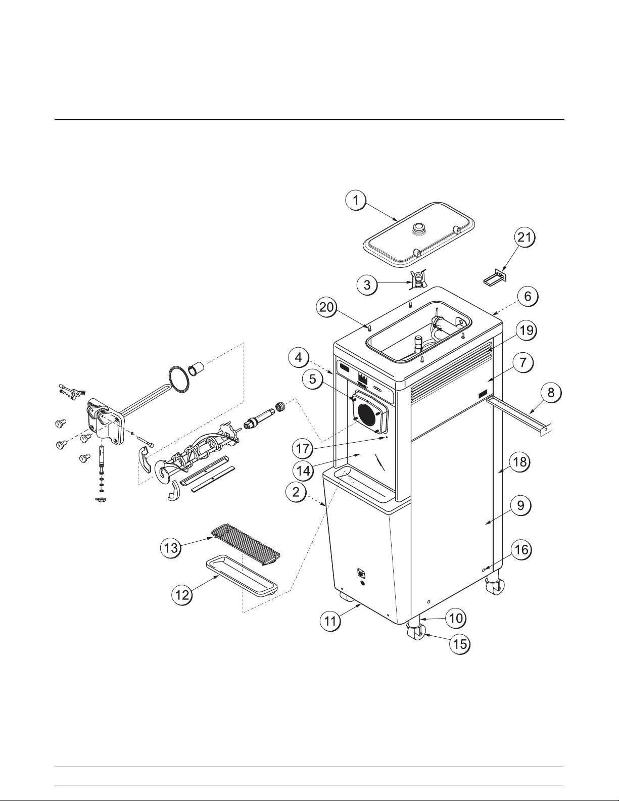
Section 4 Operator Parts Identification
PH71
4
Models PH71/PH84Operator Parts Identification
Page 9
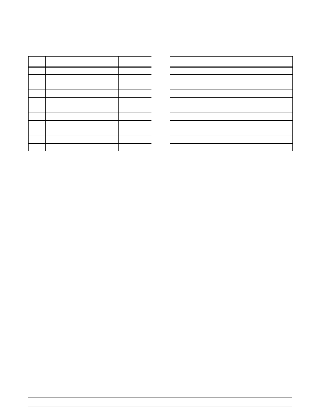
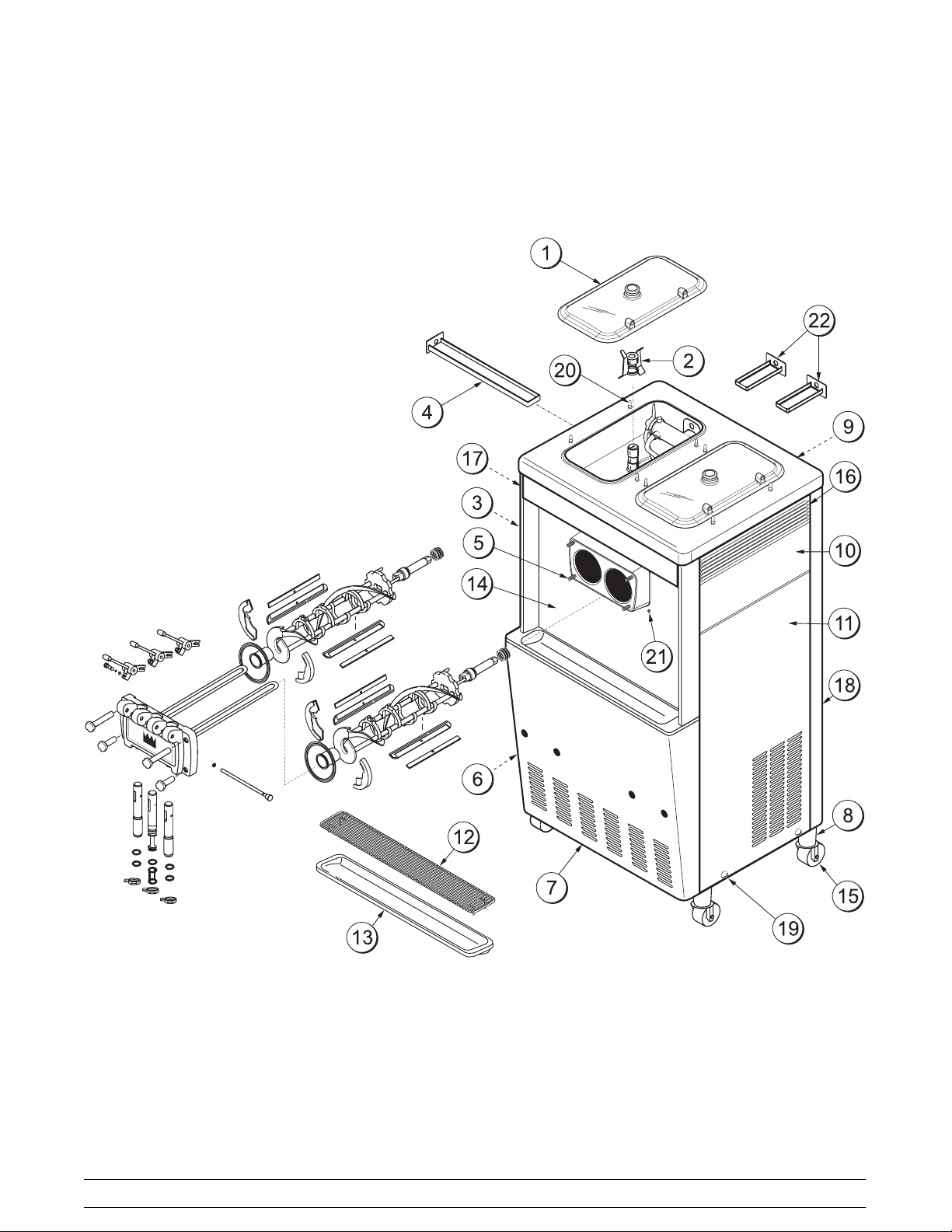
PH71 Parts Iden t ificatio n
ITEM DESCRIPTION PART NO.
1 COVER-HOPPER 053809
2 PANEL A.-LOWER SIDE X39075-SER
3 AGITATOR A. *HT*20 QT. X44797
4 PANEL-UPPER·SIDE-LEFT 024426
5 STUD-NOSE CONE 022822
6 PANEL-REAR 048203
7 PANEL-UPPER SIDE RIGHT 028823
8 PAN-DRIP 11 -5/8 LONG 027503
9 PANEL A.-LOWER SIDE X24424-SER
10 ADAPTOR A. -CASTER X18915
11 PANEL-SERVICE 045637
ITEM DESCRIPTION PART NO.
12 TRAY-DRIP 14.8 046275
13 SHIELD-SPLASH-WIRE 046177
14 PANEL A. -FRONT X45630
15 CASTER-SWV 5/8 STEM 4IN 018794
16 SCREW 011694
17 CARRIAGE BOLT 012347
18 TRIM-REAR CORNER-RIGHT 046391
19 LOUVER SIDE -R&L 017471
20 PIN-RETAINER-HOPPER CVR 043934
21 PAN-DRIP 048435
*22 TRIM-REAR CORNER-LEFT 046390
*NOT SHOWN
Models PH71/PH84 Operator Parts Identification
5
Page 10
PH84
6
Models PH71/PH84Operator Parts Identification
Page 11
PH84 Parts Iden t ificatio n
ITEM DESCRIPTION PART NO.
1 COVER-HOPPER 053809
2 AGITATOR A. *HT*20 QT. X44797
3 PANEL-UPPER SIDE LEFT 028822
4 PAN-DRIP 17-1/4”LONG 027504
5 STUD-NOSE CONE 022822
6 PANEL A.-SIDE LOWER LEFT X46447-SER
7 PANEL-SERVICE 046172
8 ADAPTOR A.-CASTER X18915
9 PANEL-REAR 051076
10 PANEL-UPPER SIDE RIGHT 028823
11 PANEL A. -SIDE LOWER RIGHT X46448-SER
12 SHIELD-SPLASH-WIRE 046170
ITEM DESCRIPTION PART NO.
13 TRAY-DRIP 22-13/16 X 5-1/8 046171
14 PANEL A. -FRONT X46167
15 CASTER-SWV 5/8 STEM 4IN 018794
16 LOUVER-SIDE-RIGHT 017471
17 LOUVER-SIDE-LEFT 028288
18 TRIM-REAR·CORNER·RIGHT 013663
19 SCREW 011694
20 PIN-RETAINER-HOPPER CVR 043934
21 CARRIAGE BOLT 012347
22 PAN-DRIP 048204
*23 TRIM-REAR·CORNER·LEFT 013761
*NOT SHOWN
Models PH71/PH84 Operator Parts Identification
7
Page 12
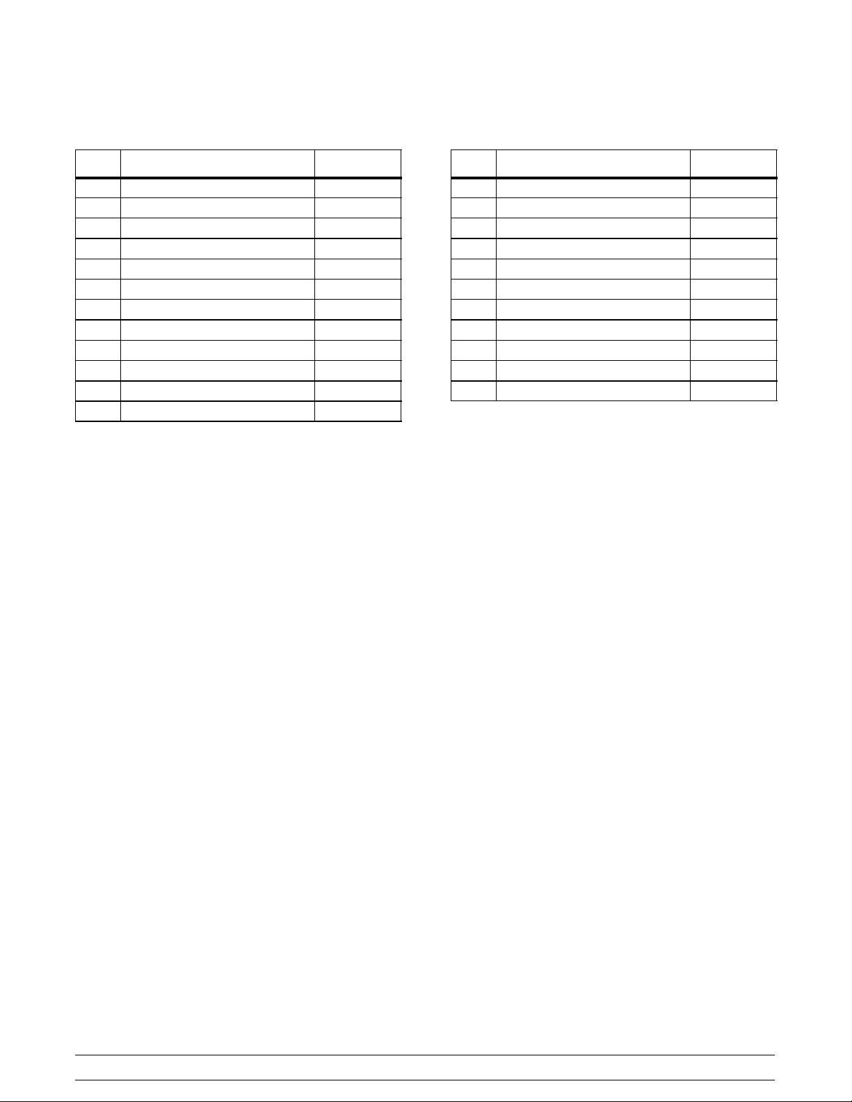
Beater Door Assembly -- PH71
ITEM DESCRIPTION PART NO.
1 SEAL--DRIVE SHAFT 032560
2 DRIVE SHAFT 032564
3 BEATER A. X46231
4 CLIP -- SCRAPER BLADE 046236
5 SCRAPER BLADE 046235
*6a BEARING--FRONT 050348
6b SHOE-- FRONT HELIX--REAR 050346
6c SHOE--FRONT HELIX --FRONT 050347
7 GASKET--DOOR 048926
8 FREEZER DOOR A. X51531-9
9 DRAW HANDLE-- ADJ . X55095
ITEM DESCRIPTION PART NO.
9a DRAW HANDLE 044197
9b SCREW--ADJUSTMENT 055092
9c O--RING--ADJ. SCREW 015872
9d NUT-5/16 -24 JAM 029639-BLK
10 O--RING--PIVOT PIN 016272
11 PIVOT PIN A. X22820
12 HAND SCREW (STUD NUT) 021508
13 DRAW VALVE A. X33582
14 O--RING--DRAW VALVE 014402
15 DESIGN CAP 014218
*USED W/FRONT HELIX SHOES 050346 & 050347
(ORDER KIT X50350)
8
Models PH71/PH84Operator Parts Identification
Page 13
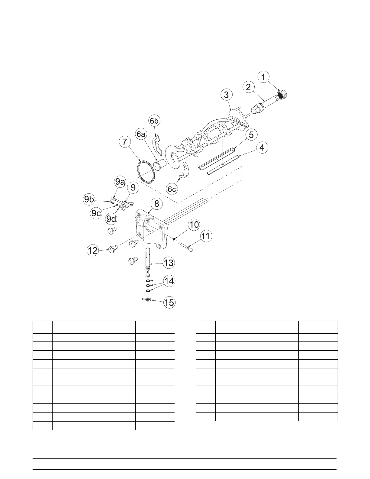
Beater Door Assembly -- PH84
ITEM DESCRIPTION PART NO.
1 SEAL-DRIVE SHAFT 032560
2 SHAFT-BEATER 032564
3 BLADE-SCRAPER 046235
4 BEATER ASSEMBLY X46231
5 CLIP-SCRAPER·BLADE 046236
*6a BEARING-FRONT 050348
6b SHOE--FRONT HELIX --REAR 050346
6c SHOE--FRONT HELIX--FRONT 050347
7 GASKET-DOOR HT 4”-DOUBLE 048926
8 DOOR-3 SPT X51532-11
9 HANDLE A.-DRAW-ADJ. STLS X33687
9a HANDLE-ADJUSTABLE 028804
Models PH71/PH84 Operator Parts Identification
ITEM DESCRIPTION PART NO.
9b SCREW-ADJUSTMENT-5/16-24 033662
9c O -RING-1/4 OD X .070W 50 015872
9d NUT-JAM 5/16 -24 029639-BLK
10 O-RING-5/16 OD X .070W 016272
11 ROD A. -PIVOT X20683
12 NUT-STUD LONG 034382
13 VALVE A. -DRAW*SELF CLEAN X33582
14 O-RING-7/8 OD X .103W 014402
15 CAP-DESIGN-1.010”ID-6POINT 014218
16 NUT-STUD SHORT 034383
17 VALVE A. -DRAW CENTER X37376
18 SEAL-DRAW VALVE 034698
*USED W/FRONT HELIX SHOES 050346 & 050347
(KIT X50350)
9
Page 14
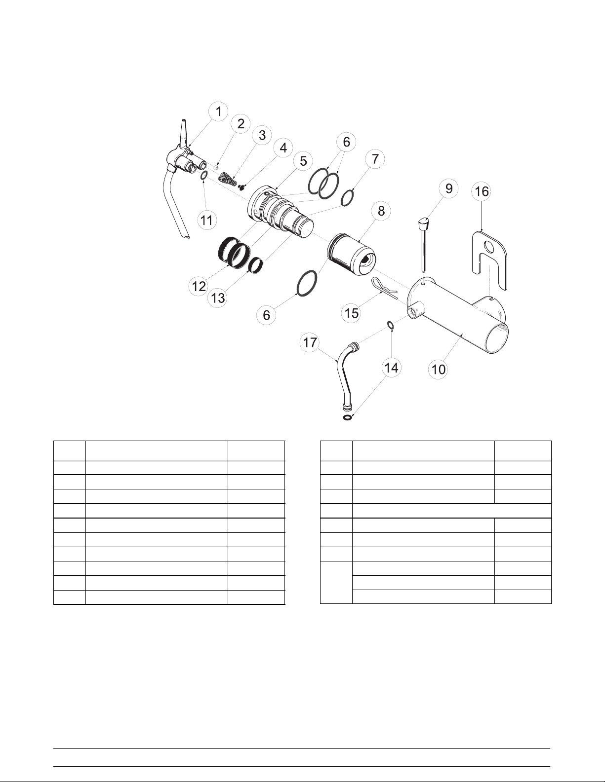
Pump Assembly X45316--B
PH71/PH84
ITEM DESCRIPTION PART NO.
1 TUBE A.-MIX INLET X45318
2 SEAL--AIR INLET FITTING 045327
3 SPRING 022456
4 POPPET 022473
5 BODY A.--COAX VALVE B X46860-B
6 O--RING-- PISTON/LVB (3) 020051
7 O--RING-- LVB 018664
8 PISTON--COAX B 045319-B
9 PIN A.--COAX PUMP X36950
10 CYLINDER A.-- PUMP X44755
ITEM DESCRIPTION PART NO.
11 O-- RING--MIX INLET TUBE 015835
12 RING--CHECK--LVB (2) 020050
13 RING-CHECK-LVB 033215
SEPARATE ITEMS:
14 O-RING-FEEDTUBE 016132
15 PIN--COTTER--HAIRPIN 044731
16 CLIP--MIX PUMP RETAINER 044641
TUBE A.--PUMP FEED (PH71) X44666
TUBE A.--PUMP FEED--L (PH84) X44662
17
TUBE A.--PUMP FEED--R (PH84) X44664
10
Models PH71/PH84Operator Parts Identification
Page 15
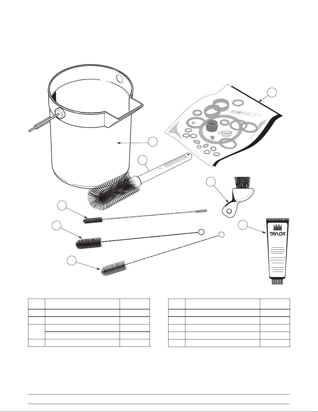
Accessories
048260
3
0
4
82
6
0
8
1
2
4
5
6
ITEM DESCRIPTION PART NO.
1 BRUSH-MIX PUMP BODY-3 X 7 023316
2 BRUSH-END-DOOR-SPOUT 039719
KIT A.-TUNE UP-PH71 X49463-8
3
KIT A.-TUNE UP-PH84 X49463-1
4 BRUSH-DOUBLE ENDED 013072
7
ITEM DESCRIPTION PART NO.
5 BRUSH-REAR BRG 1IN.D X 2IN 013071
6 BRUSH-DRAW VALVE 1”ODX2” 013073
7 LUBRICANT-TAYLOR HI PERF. 048232
8 PAIL-MIX 10 QT. 013163
* SANITIZER·KAY-5·125·PKTS 041082
*NOT SHOWN
B
U
L
H
P
R
E
Models PH71/PH84 Operator Parts Identification
11
Page 16

Section 5 Important: To the Operator
PH71
2 3 4 5 6
CLEAN
HEAT
MIX
MIX
OUT
LOW
WASH PUMP MENU
ONOFF
MODE
+++
MANUALLY
AUTO
1
PH84
7
--
--
> +++ - - -
<
WASH
PUMP AUTO MENU WASH PUMP AUTO
ONOFF
ITEM DESCRIPTION
1 POWER SWITCH (TOGGLE)
2 LCD DISPLAY
3 MIX LOW INDICATOR LIGHT
4 MIX OUT INDICATOR LIGHT
SEL
1
7
2 3 4 5 6
MIX
HEAT
MIX
OUT
LOW
CLEAN
MODE
MANUALLY
7
ITEM DESCRIPTION
5 HEAT MODE INDICATOR LIGHT
6 CLEAN MANUALLY INDICATOR LIGHT
7 KEYPADS
12
Models PH71/PH84Important: To the Operator
Page 17
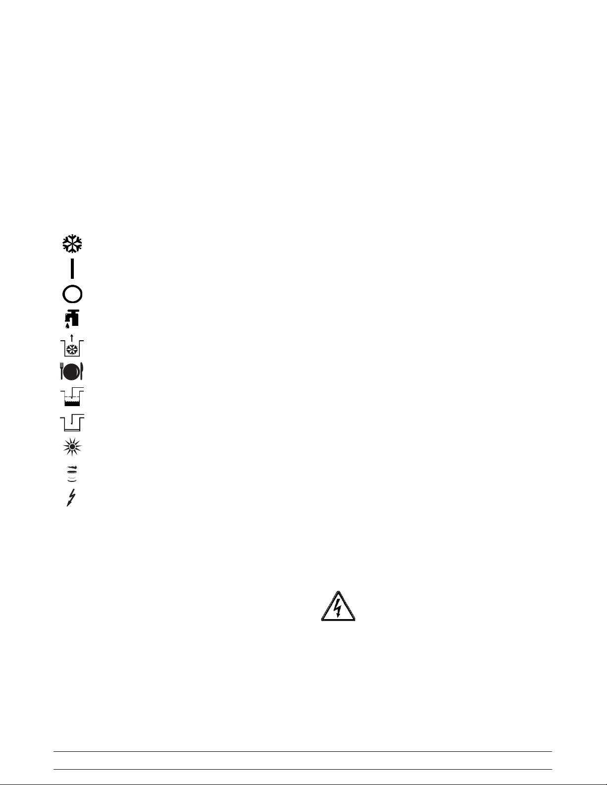
Symbol Definitions
To better communicate in the International arena, the
words on many of our operator switches and buttons
have symbols to indicate their functions. Your T aylor
equipment is designed with these International
symbols.
The following chart identifies the symbol definitions
used on the operator switches.
=AUTO
Indicator Lights
MIX LOW - When the MIX LOW light begins to flash,
it indicates the mix hopper has a low supply of mix and
should be refilled as soon as possible. On double head
units, the word “LOW” will also display on the LCD
indicator next to the word “MIX”.
MIX OUT - When the MIX OUT light begins to flash, it
indicates the mix hopper has been almost completely
exhausted and has an insufficient supply of mix to
operate the freezer . At this time, the AUTO mode is
locked out and the freezer will be placed in the
STANDBY mode. To initiate the refrigeration system,
add mix to the mix hopper and press the AUTO key.
The freezer will automatically begin operation.
=ON
=OFF
= WASH
=PUMP
=MENU
=MIXLOW
= MIX OUT
=HEATMODE
= CLEAN MANUALLY/BRUSH CLEAN
=POWER
Power Switch
When placed in the ON position, the power switch
allows softech control panel operation.
HEATMODE - When the HEAT MODE light is flashing,
it indicates that the freezer is in the process of a heat
cycle.
CLEAN MANUALLY - When the CLEAN MANUALLY
light is flashing, it indicates that the machine must be
disassembled and brush cleaned within 24 hours.
When the MIX LOW, MIX OUT, HEAT MODE, and
CLEAN MANUALLY indicator lights are all flashing,
this signifies a locked condition.
Reset Mechanism
The reset button is located in the service panel. The
Model PH84 has two reset mechanisms, one for each
side of the freezer.
The reset mechanism protects the beater motor from
an overload condition. Should an overload occur, the
reset mechanism will trip. To properly reset the freezer
place the power switch in the OFF position. Press the
reset button firmly. Turn the power switch to the ON
position. Clear the fault. Press the WASH key and
observe the freezer’s performance. Open the side
access panel to check if the beater motor is turning the
drive shaft in a clockwise (from operator end) direction
without binding.
Warning: Do not use metal objects to
press the reset button. Failure to comply may
Liquid Crystal Display
The Liquid Crystal Display (LCD) is located on the front
control panel. The LCD is used to show the current
mode of operation, and whether or not there is
sufficient mix.
Models PH71/PH84 Important: To the Operator
result in severe personal injury or death.
If it is turning properly, press the W ASH key to cancel
cycle. Press the AUTO key on both sides of the
machine to resume normal operation. If the freezer
shuts down again, contact your authorized service
technician.
13
Page 18
Air/Mix Pump Reset Mechanism
The reset button for the pump is located in the service
panel. The reset protects the pump from an overload
condition. Should an overload occur, the reset
mechanism will trip. To reset the pump, press the reset
button firmly. The Model PH84 has two pump reset
mechanisms, one for each side of the freezer.
Once the system has initialized the SAFETY
TIMEOUT screen is displayed and the alarm is turned
on.
SAFETY TIMEOUT
ANY KEY ABORTS
Warning: Do not use metal objects to
press the reset button. Failure to comply may
result in severe personal injury or death.
Adjustable Draw Handle
This unit features an adjustable draw handle to provide
the best portion control, giving a better, consistent
quality to your product and controlling costs. The draw
handle should be adjusted to provide a flow rate of 5
to 7-1/2 oz. of product by weight per 10 seconds. T o
INCREASE the flow rate, turn the screw
COUNTERCLOCKWISE, and CLOCKWISE to
DECREASE the flow rate. In addition, for purposes of
SANITIZING and RINSING, the flow rate can be
increased by removing the pivot pin and placing the
restrictive bar on the TOP. When drawing product,
always have the restrictive bar on the BOTTOM.
IMPORTANT: Once the draw rate is set, tighten the
lock nut with a wrench.
This screen will be displayed, with the alarm on, for 60
seconds or until any key is pressed.
After the safety timeout has been completed, and the
power switch is OFF, one of the following screens is
displayed.
The first screen is displayed if the machine is not in a
brush clean state. If any of the requirements for a
brush clean have not been met, the time displayed will
remain at 5:00 minutes.
PH71 Screen:
POWER SWITCH OFF
TIME: 4:40
HOPPER: 62.1
BARREL: 67.7
PH84 Screen:
POWER SWITCH OFF
OUT TIME: 4:40 OUT
68.5 HOPPER 62.1
69.5 BARREL 67.7
Operating Screen Descriptions
When the machine is powered the system will initialize.
The screen will display “INITIALIZING”. There will be
four types of data the system will check: LANGUAGE,
SYSTEM DATA, CONFIG DATA, and LOCKOUT
DATA. During the INITIALIZING... LANGUAGE
screen, the alarm will be on. If the system data,
configuration data, or lockout history data has become
corrupt, the following screen will alert the operator that
the system settings may have been changed.
NVRAM FAULT
RESET TO DEFAULTS
PRESS SEL KEY
When all the requirements for a brush cleaning are
met, and the five minutes expire, the screen will
change to the second screen, which is the standard
power switch OFF screen.
POWER SWITCH OFF
-- = -- = -- = -- = -- = -UNIT CLEANED
When the power switch is set in the ON position, the
system mode of operation screen is displayed. In this
example, the machine is ON, but no mode of operation
has been selected. The second line of the display
indicates whether there is a sufficient supply of mix in
the hopper or if there is a LOW or OUT mix condition
14
Models PH71/PH84Important: To the Operator
Page 19

(PH84 only). The third line of the display shows the
temperature of the mix hopper. After pressing the
AUTO key, the last line of the display shows the month
and date (MM = month, DD = day) that the machine
needs to be disassembled and brush cleaned.
STANDBY :MODE: WSH-- PMP
OUT :MIX: LOW
40.0F HOPPER 40.0F
BRUSH CLEAN ON: 10/31
PH71 Screen:
MODE: OFF
HOPPER TEMP: 40.0F
BRUSH CLEAN ON: MM/DD
PH84 Screen:
OFF :MODE: OFF
OK :MIX: OK
40.0F HOPPER 40.0F
BRUSH CLEAN ON: MM/DD
The next display indicates the freezer is operating in
two different modes. The following information is
given:
The machine is operating in the WASH and PUMP
modes, the temperature of the mix hopper is 40_F
(4.4_C), and the machine needs to be brush cleaned
on October 31st.
PH71 Screen:
MODE: WSH-PMP
HOPPER TEMP: 40.0 F
BRUSH CLEAN ON: 10/31
The following displays pertain to the HEAT cycle:
While in the heating phase, you will see this display. It
shows the present temperature of the hopper.
PH71 Screen:
MODE: HEAT
PHASE: HEAT
HOPPER TEMP: 140.0 F
BRUSH CLEAN ON: MM/DD
PH84 Screen:
HEAT :MODE: HEAT
HEAT :PHASE: HEAT
140.0F HOPPER 140.0F
BRUSH CLEAN ON: MM/DD
The mix temperature must be raised above 151_F
(66.1_C) within 90 minutes or the freezer will be locked
in STANDBY, and the cycle failure display will appear.
In the example, the hopper temperature is 140_F
(60_C). The phase shows that the machine is in the
heat phase of the heat treatment cycle.
When the heating phase is complete, the freezer goes
into the holding phase of the cycle. The holding phase
will hold the temperature above 151_F (66.1_C) for a
minimum of 30 minutes.
In this example, the hopper temperature is 151_F
(66.1_C).
PH71 Screen:
MODE: HEAT
PH84 Screen:
The next display indicates the freezer is operating in 3
PHASE: HOLD
HOPPER TEMP: 151.0 F
BRUSH CLEAN ON: MM/DD
different modes. The following information is given:
The left side of the freezer is operating in the
PH84 Screen:
STANDBY mode, and the mix level in the hopper is
OUT. The right side is operating in the WASH and
PUMP modes, and the mix level in the hopper is LOW.
The temperature of the mix in both hoppers is 40_F.
(4.4_C.), and the machine needs to be brush cleaned
HEAT :MODE: HEAT
HOLD :PHASE: HOLD
151.0F HOPPER 151.0F
BRUSH CLEAN ON: MM/DD
on October 31st.
Models PH71/PH84 Important: To the Operator
15
Page 20

The final phase of the heat treatment cycle is the
cooling phase. Now the freezer must cool the mix
below 41_F(5_C). If the product fails to cool in two
hours, the freezer will lock out.
This example illustrates that the temperature is being
lowered, but has not yet reached the set point.
PH71 Screen:
MODE: HEAT
PHASE: COOL
HOPPER TEMP: 55.0 F
BRUSH CLEAN ON: MM/DD
PH84 Screen:
HEAT :MODE: HEAT
COOL :PHASE: COOL
55.0F HOPPER 55.0F
BRUSH CLEAN ON: MM/DD
The entire heat treatment cycle must be completed in
four hours.
When the entire heat cycle has been completed, the
normal display will appear, showing the machine in the
STANDBY mode. The machine may now be placed in
the AUTO mode or left in the STANDBY mode.
PH71 Screen:
14 DAY TIMEOUT
CLEANING REQ’D
FREEZER LOCKED
PRESS SEL KEY
2. There has been a thermistor failure (freezing
cylinder, hopper, or glycol) during the heat
treatment process.
SYSTEM FAULT
SERVICE REQ’D
FREEZER LOCKED
PRESS SEL KEY
All four LED’s on the front of the freezer will light. Press
the SEL key.
The next display is the screen which will appear after
the failure message. To comply with health codes, heat
treatment system freezers must complete a heat
treatment cycle daily, and must also be brush cleaned
every 14 days. Brush cleaning is the normal
disassembly and cleaning procedures. Failure to
follow these guidelines will cause the control to lock the
freezer out of the AUTO mode. Press the WASH key.
NO AUTO OPERATION
ALLOWED UNTIL
BRUSH CLEANING
PRESS WASH KEY
MODE: STANDBY
HOPPER TEMP: 41.0 F
BRUSH CLEAN ON: MM/DD
PH84 Screen:
STANDBY :MODE: STANDBY
OK :MIX: OK
41.0F HOPPER 41.0F
BRUSH CLEAN ON: MM/DD
Hard Lock: There are two causes for a hard lock:
1. Fourteen days have elapsed since the last
brush cleaning. The following screen will be
displayed.
The next display is the screen which will appear after
the brush cleaning message and illustrates that the
control is in the OFF mode and the machine needs to
be disassembled and brush cleaned.
PH71 Screen:
MODE: OFF
HOPPER TEMP: 41.0 F
FREEZER LOCKED
PH84 Screen:
OFF :MODE: OFF
OK :MIX: OK
41.0F HOPPER 41.0F
FREEZER LOCKED
16
Models PH71/PH84Important: To the Operator
Page 21

Soft Lock: If a heat treatment cycle has not been
initiated within the last 24 hours, all four LED’s on the
front of the machine will light and a message will
appear on the LCD. Line 3 of the LCD will indicate the
reason the message appears. Following are the
variable messages which will appear on line 3:
1. POWER SWITCH OFF: Power switch was in
the OFF position.
2. MIX OUT PRESENT: There was mix out
condition present.
3. AUTO OR STANDBY OFF: The unit was not in
the AUTO or STANDBY mode.
4. NO HEAT CYCLE TRIED: A heat treatment
cycle was not attempted in the last 24 hours.
(AUTO HEAT TIME was advanced, or a power
loss was experienced at the time the cycle was
to occur, or a heat cycle failure not due to a
thermistor failure.)
NO HEAT TREAT START
BECAUSE
VARIABLE MESSAGE
PRESS SEL KEY
If the following screen appears, a soft lock has
occurred during the heat treatment cycle.
pressing the AUTO key), or to disassemble and brush
clean the freezer. If the AUTO key is pressed, the
freezer will automatically start the heat treatment cycle
and only the heat cycle LED will light.
NO AUTO OPERATION
ALLOWED. PRESS
AUTO FOR HEAT CYCLE
WASH TO BRUSH CLEAN
If the WASH key is pressed, the next display will
appear and the freezer will have to be disassembled
and brush cleaned.
PH71 Screen:
MODE: OFF
HOPPER TEMP: 41.0F
FREEZER LOCKED
PH84 Screen:
OFF :MODE: OFF
OK :MIX: OK
41.0F HOPPER 41.0F
FREEZER LOCKED
HEAT TREAT CYCLE
FAILURE
FREEZER LOCKED
PRESS SEL KEY
If the temperature of the product has not fallen below
41_F(5_C) by the end of the COOL cycle, the following
screen will appear.
PRODUCT OVER TEMP
FREEZER LOCKED
PRESS SEL KEY
Press the SEL key to advance to the next display.
When one of these messages appears, automatic
freezer operation cannot take place until the freezer is
disassembled and brush cleaned or has completed a
heat treatment cycle. The next display will instruct the
operator to start a heat treatment cycle manually (by
Once the freezer is unlocked by starting a heat
treatment cycle, only the heat cycle LED will light. If the
freezer is unlocked by brush cleaning, the mix low and
mix out LED’s will light.
Operator Menu
The OPERATOR MENU is used to enter the operator
function displays. To access the OPERATOR MENU,
simply press the MENU key. The cursor will flash under
the letter “A” indicating that this is screen “A”. To select
a different screen, use the arrow keys and move the
cursor to the desired screen selection and press the
SEL key.
OPERATOR MENU
BCDEFGHIJ
A
EXIT FROM MENU
<--- ---> SEL
Models PH71/PH84 Important: To the Operator
17
Page 22

Screen “B” is FAULT DESCRIPTION. The fault
description will indicate if there is a fault with the
freezer and the side of the freezer where the fault
occurred. To clear the tone for any faults which have
been corrected, press the left arrow key. To see if there
is more than one fault per cylinder, press the SEL key.
When the last fault is displayed, the control will return
to the OPERATOR MENU. To return to the main
screen, move the cursor to “A” and press the SEL key
again.
Listed below are the variable messages which will
appear, along with the corrective action:
a. The barrel (freezing cylinder) temperature
reaches 41_F. (5_C.) or higher after a power
failure.
b. The barrel (freezing cylinder) temperature
has not fallen below 41_F. ( 5 _C.) by the end
of the COOL phase in the heat cycle.
10. POWER FAILURE: This message will appear
in the FAUL T DESCRIPTION if a power failure
has occurred. Clear the tone.
PH71 Screen:
1. NO FAULT FOUND: There was no fault found
in the freezer. Nothing will appear on the screen
after this variable message appears.
2. BEATER OVERLOAD: Press the reset button
firmly. Clear the tone.
3. HPCO COMPRESSOR: Place the power
switch in the OFF position. Wait 5 minutes for
the machine to cool. Place the power switch in
the ON position. Clear the tone.
4. COMP ON TOO LONG: Place the power
switch in the OFF position. Call a service
technician. Clear the tone.
5. HOPPER THERM BAD: Place the power
switch in the OFF position. Call a service
technician.
6. BARREL THERM BAD: Place the power
switch in the OFF position. Call a service
technician.
7. GLYCOL THERM BAD: Place the power
switch in the OFF position. Call a service
technician.
8. HOPPER OVER TEMP: The hopper
temperature has risen too high as follows. Clear
the tone.
FAULT DESCRIPTION
VARIABLE MESSAGE
CLR SEL
PH84 Screen:
FAULT DESCRIPTION
L: VARIABLE MESSAGE
R: VARIABLE MESSAGE
CLR SEL
Screen “C” is SET CLOCK. This screen will display the
current date and time. The date and time may be
changed only after the freezer has been manually
brush cleaned, but before it has been placed in the
AUTO mode. Move the cursor under the number you
wish to change. Press the plus key to increase the
number; press the minus key to decrease the number .
When the desired time and date appears, press the
SEL key once to return to the OPERAT OR MENU.
SET CLOCK
10:21 AM 06/07/2001
-- --
<--- ---> +++ ------ SEL
a. The hopper temperature reaches 41_F.
(5_C.) or higher after a power failure.
b. The hopper temperature has not fallen below
41_F. ( 5_C.) by the end of the COOL phase
in the heat cycle.
9. BARREL OVER TEMP: The barrel (freezing
cylinder) temperature has risen too high as
follows. Clear the tone.
If an illegal date is entered, the following screen will
appear. The correct date must be entered before
leaving this display.
SET CLOCK
10:34 AM 02/30/2001
-- -- I N V A L I D D A T E
<--- ---> +++ ------ SEL
18
Models PH71/PH84Important: To the Operator
Page 23

Screen “D” is SYSTEM INFORMATION. The first
screen indicates the software version used in the unit.
SOFTWARE VERSION
PH71 Control UVC2
Version 2.00
SEL
Press the SEL key to view the second screen of the
SYSTEM INFORMATION display. This screen indicates the language, version number and language
strings used in the unit.
Language
V1.10r00 English 459
SEL
Press the SEL key to view the third screen of the
SYSTEM INFORMATION display. This screen
indicates the Bill of Material number and serial number
of the unit. Press the SEL key once to return to the
OPERATOR MENU.
Press the SEL key once to view the SERVINGS
COUNTER screen.
PH71 Screen:
VISC HOPPER BARREL
0 38.5 28.5
TIME C 11:00 11:00
PH84 Screen:
VISC HOPPER BARREL
0 38.5 28.5
0.0 38.5 18.0
TIME C 11:00 11:00
The SERVINGS COUNTER screen indicates the
number of times the draw switch has closed (number
of draws) since the last brush cleaning or since the last
serving counter reset. A maximum of 32,767 draws
can be recorded; an additional draw will cause the
counter to restart at zero. Pressing the SEL key will
return the display to the OPERATUR MENU.
B.O.M. PH7133B000
S/N K0000000
SEL
Screen “E” is AUTO HEAT TIME. This screen is used
to set the time of day in which the heat treatment cycle
will start. Move the cursor under the number you wish
to change. Press the plus key to increase the number;
press the minus key to decrease the number. When
the desired time appears, press the SEL key once to
return to the OPERATOR MENU.
AUTO HEAT TIME
TIME: 12:00 AM
-- --
<--- ---> +++ ------ SEL
Screen “F” is CURRENT CONDITIONS. This screen
gives the viscosity of the product and the hopper and
barrel temperatures. The last line of the display is the
compressor countdown safety timer. The safety timer
prevents the compressor from running more than 11
minutes (other than during the cooling phase of the
heat treatment cycle).
PH71 Screen:
SERVINGS COUNTER
DRAWS
12
SEL
PH84 Screen:
SERVINGS COUNTER
LEFT RIGHT
12 15
SEL
Draws are counted during the AUTO mode of
operation only.
Screen “G” is HEAT CYCLE DATA. The information
from the previous heat treatment cycles can be
obtained through this screen. The most recent heat
treatment cycle data will be shown first; press the plus
key to scroll through the remaining heat cycle displays.
If a heat treatment cycle failure should occur, a 2
character message will appear on the second line of
the screen. Press the SEL key once to return to the
OPERATOR MENU.
Models PH71/PH84 Important: To the Operator
19
Page 24

Listed below are the variable messages which could
appear:
HT Failure in the heating phase.
CL Failure in the cooling phase.
TT Failure in meeting total heat treatment cycle
time requirement.
MO Mix out condition.
OP Operator interruption.
PF Power failure. (If a power failure occurs, but
the heat treatment cycle does not fail, an
asterisk (*) will appear on the third line of the
display.)
Screen “H” is the LOCKOUT HISTORY. This screen
displays a history of the last 40 hard locks, soft locks,
and brush clean dates. Page numbers are indicated in
the upper right hand corner. Page 1 always contains
the most recent failure. Press the PUMP key to cycle
through the pages.
The second line of the screen displays the date and
time a failure occurs. The third line indicates the
reason for a failure, or will indicate a successful brush
cleaning has occurred. Some failures occur for
multiple reasons. When this occurs, a page will be
generated for each reason. Press the SEL key once to
return to the OPERATOR MENU, or twice to return to
the Main Screen.
BO Beater overload.
HO High pressure cut-out.
TH Failed thermistor probe.
PS Power switch placed in the OFF position.
ML Mix Low Condition.
14 14 Day Timeout Occurred.
RC Heat Cycle Record Cleared.
11/07 02:00 05:09
HEAT OVER COOL XX
01:09 00:45 01:14
TEMP AT END 38.5 1
Pressing the left arrow key on any HEAT CYCLE DATA
screen will cause the extended data screen to be
displayed. This screen shows the hopper, barrel, and
glycol temperatures, and the amount of time the
freezer spent in the phases of the heat cycle when the
heat cycle completed, or was terminated.
PH71 Screen:
LOCKOUT HISTORY 1
06/11/01 02:08
SOFTLOCK ABORT
+ + + -- -- -- S E L
Screen “I” is the SERVICE MENU. This screen can
only be accessed by a service technician.
Screen “J” is the STANDBY MODE. To place the
freezer in the STANDBY mode, move the cursor under
the word “yes”. Press the SEL key to execute the
command. Pressing the SEL key again will return you
to the main screen. To exit the STANDBY mode and
place the unit in AUTO, press the AUTO key once.
Pressing the AUTO key again will place the unit in the
OFF mode.
PH71 Screen:
STANDBY MODE
STANDBY YES NO
-- -- --
<--- ---> SEL
HOPPER BARREL GLYCOL
151.0 134.5 178.0
PHASE TIME: 1:20 1
PH84 Screen:
HOPPER BARREL GLYCOL
151.0 134.5 98.1
153.0 136.0
PHASE TIME: 1:20 1
PH84 Screen:
STANDBY MODE
LEFT YES NO
<--- ---> SEL
STANDBY MODE
RIGHT YES NO
<--- ---> SEL
20
-- -- --
-- -- --
Models PH71/PH84Important: To the Operator
Page 25

Section 6 Operating Procedures
The “Operator Parts Identification” section in this
manual has been included to identify components
referenced in these instructions. If this is the first time
you have read these procedures, please turn to the
“Operator Parts Identification” section, and familiarize
yourself with these components before proceeding
with the instructions.
Each unit stores mix in a hopper. The mix then flows
through a mix feed tube down into the freezing
cylinder. They both have 3.4 quart (3.2 liter) capacity
freezing cylinders and 20 quart (18.9 liter) mix
hoppers; one each for the Model PH71 and two each
for the Model PH84.
Duplicate, where they apply, the following steps for the
two freezing cylinders on the Model PH84.
We begin our instructions at the point where we enter
the store in the morning and find the parts
disassembled and laid out to air dry from the previous
night’s cleaning.
The following procedures will show you how to
assemble the parts into the freezer, sanitize them, and
prime the freezer with fresh mix in preparation to serve
your first product.
Step 1
Lubricate the groove and shaft portion that come in
contact with the bearing on the beater drive shaft. Slide
the seal over the shaft and groove until it snaps into
place. DO NOT lubricate the hex end of the drive shaft.
Fill the inside portion of the seal with 1/4” more
lubricant. Lubricate the flat side of the seal that comes
in contact with the bearing.
Figure 1
If you are disassembling the machine for the f irst time
or need information to get to this starting point in our
instructions, turn to page 36 “Disassembly” and start
there.
Assembly
Note: When lubricating parts, use an approved food
grade lubricant (Example: Taylor Lube HP).
MAKE SURE POWER SWITCH IS IN THE
“OFF” POSITION! Failure to follow this instruction
may result in severe personal injury from hazardous
moving parts.
Be certain your hands are sanitized before
assembling the freezer.
Note: Make sure the seal is not installed inside-out.
The ridge that protrudes in the center of the sealshould
be on the outside.
Figure 2
Models PH71/PH84 Operating Procedures
21
Page 26

Install the drive shaft. Insert the drive shaft into the
freezing cylinder, hex end first, and into the rear shell
bearing until the seal fits securely over the rear shell
bearing. Be certain the drive shaft fits into the drive
coupling without binding.
Figure 3
Step 2
Install the beater assembly. First check the scraper
blades for any nicks or signs of wear. If any nicks are
present, or if the blades are worn, replace both blades.
If the blades are in good condition, install the scraper
blade clips over the scraper blades. Place the rear
scraper blade over the rear holding pin on the beater.
Note: The hole on the scraper blade must fit securely
over the pin to prevent costly damage.
Holding the rear blade on the beater, slide it into the
freezing cylinder halfway. Install the front scraper
blade over the front holding pin.
Figure 5
Install the beater shoes.
USE EXTREME CAUTION when handling
the beater assembly. The scraper blades are very
sharp and may cause injury.
Figure 4
Figure 6
Slide the beater assembly the rest of the way into the
freezing cylinder.
22
Models PH71/PH84Operating Procedures
Page 27

Make sure the beater assembly is in position over the
drive shaft. Turn the beater slightly to be certain that
the beater is properly seated. When in position, the
beater will not protrude beyond the front of the freezing
cylinder.
Figure 7
Duplicate these procedures for the other side of
the freezer on the Model PH84.
Step 4
Install the freezer door. Insert the baffle rod(s) through
the opening in the beater assembly(ies) and seat the
door flush with the freezing cylinder(s). With the door
seated on the freezer studs, install the handscrews.
Tighten equally in a criss-cross pattern to insure the
door is snug.
Step 3
Assemble the freezer door. Place the large rubber
gasket(s) in the groove(s) on the back side of the
freezer door.
Slide the white plastic front bearing(s) onto the bearing
hub(s), making certain that the flanged end of the
bearing is resting against the freezer door. DO NOT
lubricate the gasket(s) or the front bearing(s).
Figure 8
Note: There are two gaskets and two front bearings
for the Model PH84 door, one for each freezing
cylinder.
Figure 9
Note: On the Model PH84, the short handscrews go
on the bottom and the long handscrews go on top.
Step 5
Install the draw valve(s). Slide the three o-rings into the
grooves on the draw valve(s) and lubricate.
Figure 10
Models PH71/PH84 Operating Procedures
23
Page 28

Lubricate the inside of the freezer door spout(s), top
and bottom, and insert the draw valve(s) from the
bottom until the slot in the draw valve(s) comes into
view.
Figure 11
Figure 13
Slide the fork of the draw handle over the bar in the slot
of the draw valve. Secure with pivot pin.
Note: The Model PH84 has three draw valves. For
the left and right draw valves, follow the assembly and
lubrication procedures explained previously. The
center draw valve uses a seal and an o-ring. Slide the
seal and o-ring into the grooves on the draw valve, and
lubricate.
Figure 12
Figure 14
Note: The Model PH84 has three draw handles. Slide
the fork of the draw handle in the slot of the draw valve,
starting from right to left. Slide the pivot pin through
each draw handle as you insert them into the draw
valves.
Step 6
Install the draw handle(s). Slide the o-ring into the
groove on the pivot pin, and lubricate.
24
Figure 15
Models PH71/PH84Operating Procedures
Page 29

Step 7
Snap the design cap(s) over the bottom of the door
spout(s).
Step 8
Install the front drip tray and the splash shield under
the door spout(s).
Air/Mix Pump Assembly
The purpose of the air/mix pump is to meter a specific
amount of air and mix, and transfer this combination to
the freezing cylinder.
Step 1
Assemble the piston. Slide the o-ring into the groove
on the piston. DO NOT lubricate this o-ring.
Figure 18
Figure 16
Step 9
Slide the long drip pan into the hole in the side panel.
Figure 17
Step 2
Assemble the valve body. Slide the three check rings
and three o-rings into the grooves on the valve body.
DO NOT lubricate the check rings or o-rings.
Note: Check rings have two smooth surfaces. A
concave shape indicates an incorrect assembly. Turn
the check ring inside out to correctly expose the flat
surface.
Figure 19
Models PH71/PH84 Operating Procedures
25
Page 30

Step 3
Put a small amount of lubricant on the inside diameter
of the piston. Insert the valve body into the piston.
Insert the assembled piston and valve body into the
pump cylinder and push upwards. Align the steel
button at the base of the valve body with the cut-out
groove at the bottom of the pump cylinder.
Figure 20
Step 4
Apply a small amount of lubricant to the LOWER inside
diameter of the pump cylinder to a depth equivalent to
the length of your index finger. Once applied, the
amount of lubricant should be equal to a paper-thin
film.
Figure 21
Figure 22
Note: The drive hole in the piston must be visible
through the drive hole in the pump cylinder.
Step 5
Assemble the mix inlet tube assembly. Slide the o-ring
and seal into the grooves on the inlet fittings and
thoroughly lubricate.
Figure 23
26
Models PH71/PH84Operating Procedures
Page 31

Attach the spring and poppet to the end of the pressure
relief fitting. The spring must be securely fastened and
not allowed to float freely.
Secure the pump parts in position by sliding the
retaining pin through the cross holes located at the
bottom of the pump cylinder.
Figure 24
Note: The spring and rubber poppet act as a pressure
relief valve to prevent a pressure build up in the
freezing cylinder.
Step 6
Insert the mix inlet tube assembly into the holes in the
base of the valve body.
Figure 25
Figure 26
Note: The head of the retaining pin should be facing
UP with the pump correctly installed.
Step 7
Install one o-ring on each end of the mix feed tube, and
thoroughly lubricate.
Figure 27
Models PH71/PH84 Operating Procedures
27
Page 32

Step 8
Slide the large o-ring and two cup seals into the
grooves on the drive shaft. Thoroughly lubricate the
o-ring, seals, and shaft. DO NOT lubricate the hex end
of the shaft.
Step 9
Lay the agitator, pump assembly , pump clip, mix feed
tube, and locking clip in the bottom of the mix hopper
for sanitizing.
Figure 30
Repeat Steps 1 through 9 for the other side of the
freezer on the Model PH84.
Figure 28
Note: The open end of the cup seal must face away
from the hex end.
Install the hex end of the drive shaft into the drive hub
at the rear wall of the mix hopper.
Figure 29
Sanitizing
Step 1
Prepare two gallons (7.6 liters) of an approved 100
PPM sanitizing solution (example: Kay-5r). USE
WARM WATER AND FOLLOW THE MANUFACTURER’S SPECIFICATIONS.
Step 2
Pour the two gallons (7.6 liters) of sanitizing solution
over all the parts in the bottom of the mix hopper and
allow it to flow into the freezing cylinder.
Figure 31
Note: You have just sanitized the mix hopper and
parts; therefore, be sure your hands are clean and
sanitized before going on in these instructions.
28
Models PH71/PH84Operating Procedures
Page 33

Step 3
Allow the sanitizing solution to flow into the freezing
cylinder. While the solution is flowing into the freezing
cylinder, take particular care to brush-clean the mix
level sensing probe on the front wall and the bottom of
the hopper, the mix hopper, the mix hopper gasket, the
mix inlet hole, the air/mix pump, the pump clip, the mix
feed tube, and the locking clip.
Step 4
Install the pump assembly. To position the pump on the
drive hub at the rear of the mix hopper, align the drive
hole in the piston, with the ball crank of the drive shaft.
Secure the pump in place by slipping the pump clip
over the collar of the pump, making sure the clip fits
into the grooves in the collar.
Step 6
Place the power switch in the ON position.
Step 7
Press the WASH key and allow the sanitizing solution
in the freezing cylinder to agitate for five minutes.
Figure 34
Step 8
Place a pail beneath the door spout(s). Press the
PUMP key. Open and close the draw valve six times.
Figure 32
Step 5
Push one end of the vinyl sanitizing tube onto the air
inlet tube for the pump. Be sure the free end is
submerged in the sanitizing solution in the hopper.
Figure 33
Repeat Steps 1 through 5 for the other side of the
freezer on the Model PH84.
Figure 35
Models PH71/PH84 Operating Procedures
29
Page 34

Open the draw valve and draw off the remaining
sanitizing solution.
10296
Figure 36
(Note: On the Model PH84, momentarily open the
center draw valve to sanitize the center door spout.)
Press the PUMP key to stop pump operation.
Step 9
Press the WASH key and close the draw valve(s).
Figure 38
Note: Be sure your hands are clean and sanitized
before going on in these instructions.
Step 10
Place the agitator on the agitator housing.
Figure 37
Remove the vinyl sanitizing tube from the air/mix
pump.
Figure 39
Note: If agitator should stop turning during normal
operation, with sanitized hands, remove the agitator
from the agitator housing and brush clean with
sanitizing solution. Install the agitator back onto the
agitator housing.
30
Models PH71/PH84Operating Procedures
Page 35

Step 11
Stand the mix feed tube in the corner of the mix hopper.
Place the locking clip in position in the outlet fitting of
the pump.
Figure 40
Repeat Steps 7 through 11 for the other side of the
freezer on the Model PH84.
Step 12
Remove the design cap(s).
Step 13
Return to the freezer with a small amount of sanitizing
solution. Dip the end brush into the sanitizing solution
and brush clean the door spout(s) and bottom of the
draw valve(s).
Note: To assure sanitary conditions are maintained,
brush clean each item for a total of 60 seconds,
repeatedly dipping the brush in sanitizing solution.
Step 14
Install the design cap(s).
Priming
Note: Evaluate the condition of LED’s (lights) and
screen messages before performing priming
procedures. If all 4 LED’s are flashing, the unit is
locked.
Step 1
With a pail beneath the door spout(s), open the draw
valve. Pour two gallons (7.6 liters) of FRESH mix into
the mix hopper and allow it to flow into the freezing
cylinder. This will force out any remaining sanitizing
solution. When full strength mix is flowing from the
door spout, close the draw valve.
10296
Figure 41
Step 2
When the mix stops bubbling down into the freezing
cylinder, insert the mix feed tube. Remove the locking
clip from the outlet fitting of the mix pump. Insert the
outlet end of the mix feed tube into the mix inlet hole
in the mix hopper. Place the inlet end of the mix feed
tube into the outlet fitting of the mix pump. Secure with
locking clip.
Note: You have just sanitized all food contact
surfaces of the freezer.
Figure 42
Models PH71/PH84 Operating Procedures
31
Page 36

Step 3
Press the AUTO key. When the unit cycles off, the
product will be ready to serve.
Figure 43
Step 4
Fill the hopper with FRESH mix. Place the mix hopper
cover in position.
Daily Closing Procedures
THIS PROCEDURE MUST BE PERFORMED ONCE
EVERY 24 HOURS.
The function of the Heat Treatment Cycle is to destroy
bacteria by raising the temperature of the mix in the
freezing cylinder and the hopper to a specified
temperature for a specified period of time, and then
bringing the temperature back down low enough to
retard spoilage. The Heat Treatment Cycle will start at
the time designated in the AUTO HEAT TIME.
IMPORTANT: The level of mix in the mix hoppers
must be at the line on the agitator paddle. (The mix
low light must not be on.)
Step 1
The freezer must be in the STANDBY or AUTO mode
before the Heat Treatment Cycle may be started.
(BothsidesofthePH84mustbeinSTANDBYor
AUTO.)
Step 2
Remove the hopper cover(s). Remove the front drip
tray, splash shield, and the rear drip pan(s), and take
them to the sink for further cleaning and sanitizing.
Figure 44
Note: Use only FRESH mix when priming the freezer.
Repeat Steps 1 through 4 for the other side of the
freezer on the Model PH84.
Note: These units feature adjustable draw handles to
provide the best portion control, giving a better,
consistent quality to your product, and controlling
costs. The draw handles can be adjusted for different
flow rates. See page 14 for more information on
adjusting these handles.
IMPORTANT! Once the draw rate is set, tighten the
lock nut with a wrench.
MAKE SURE YOUR HANDS ARE CLEAN
AND SANITIZED BEFORE PERFORMING THESE
NEXT STEPS.
Note: Pressing the <-- -- key will stop agitator
movement for 10 seconds. At end of 10 seconds,
press the <-- -- key again to return to the mode screen.
Remove the agitator(s) from the mix hopper(s).
Remove the design cap(s) from the freezer door
spout(s). Take the agitator(s), hopper cover(s) and
design cap(s) to the sink for further cleaning and
sanitizing.
Rinse these parts in cool, clean water. Prepare a small
amount of an approved cleaning solution (example:
Kay-5r). USE WARM WATER AND FOLLOW THE
MANUFACTURER’S SPECIFICATIONS. Brush clean
the parts. Place the design cap(s), front drip tray and
splash shield on a clean, dry surface to air-dry
overnight or until the heating cycle is complete.
Prepare a small amount of an approved 100 PPM
sanitizing solution in WARM WATER AND FOLLOW
THE MANUFACTURER’S SPECIFICATIONS. Sanitize the drip pan(s), agitator(s) and hopper cover(s).
32
Models PH71/PH84Operating Procedures
Page 37

Step 3
Important: Install the agitator(s) back onto the
agitator housing(s). Replace the hopper cover(s).
Step 4
Return to the freezer with a small amount of cleaning
solution. With a pail beneath the door, dip the end
brush into the cleaning solution and brush clean the
door spout(s) and bottom of the draw valve(s). (See
Figure 45.)
Figure 45
The option is given to press the AUTO key which will
begin a new heat cycle or to press the WASH key
which will place the side(s) into the OFF mode to allow
a brush clean of the unit.
Daily Opening Procedures
Evaluate the condition of LED’s (lights) and screen
messages (Hard Lock or Soft Lock, etc.) before
performing opening procedures. As indicated in the
illustration below, 4 flashing LED’s, indicate a “locked”
condition.
Note: To assure sanitary conditions are maintained,
brush each item for a total of 60 seconds, repeatedly
dipping the brush in cleaning solution.
Rinse a single service towel in cleaning solution and
wipe down the freezer door and the area around the
bottom of the freezer door.
Note: Once the heating cycle has started, it cannot be
interrupted. The heating cycle will take a maximum of
4 hours to complete with full hopper(s).
CAUTION: Do not draw product or attempt
to disassemble the unit during the Heat Treatment
Cycle. The product is hot and under extreme
pressure.
When the heating cycle is complete, the control will
return to the STANDBY mode.
There are 3 phases of the heat cycle: Heating, Holding
and Cooling. Each phase has a time limit. If any one
of the three phases fail to reach the proper
temperatures within the time limit, the cycle will
automatically abort and return to the STANDBY mode.
The LCD will display the message: HEAT TREAT
CYCLE FAILURE - FREEZER LOCKED - PRESS
SEL KEY. The product may not be safe to serve. The
freezer will be locked (softlock) out of the AUTO mode.
Figure 46
Note: If the unit is hard locked, refer to the “Manual
Brush Cleaning” section starting on page 34.
Step 1
When the heating cycle is complete, the normal display will appear, showing the machine in the STANDBY mode. Prepare a small amount of an approved 100
PPM sanitizing solution (example: Kay-5r). USE
WARM WATER AND FOLLOW THE MANUFACTURER’S SPECIFICATIONS.
Sanitize the design cap(s), front drip tray, and the
splash shield in this solution.
Models PH71/PH84 Operating Procedures
33
Page 38

Step 2
Return to the freezer with a small amount of sanitizing
solution. With a pail beneath the door, dip the end
brush into the sanitizing solution and brush clean the
door spout(s) and bottom of the draw valve(s).
Figure 47
Note: To assure sanitary conditions are maintained,
brush clean each item for a total of 60 seconds,
repeatedly dipping the brush in sanitizing solution.
Install the design cap(s) on the freezer door spout(s).
(See Figure 48.)
Step 3
When ready to resume normal operation, press the
AUTO key. (See Figure 49.)
Figure 49
Note: This procedure should be done 15 minutes
before product is expected to be served.
Manual Brush Cleaning
Figure 48
Rinse a single service towel in sanitizing solution, and
wipe down the freezer door and area around the
bottom of the freezer door. Install the front drip tray and
splash shield.
THIS PROCEDURE MUST BE DONE EVERY 14
DAYS!
ALWAYS FOLLOW LOCAL HEALTH CODES.
To disassemble your unit, the following items will be
needed:
S Two cleaning pails
S Necessary brushes (provided with freezer)
S Cleaning solution
S Sanitizing solution
S Single service towels
34
Models PH71/PH84Operating Procedures
Page 39

Draining Product From The Freezing
Cylinder
Step 1
Press the AUTO key, cancelling compressor and
beater motor operation.
Figure 50
Step 4
When the flow of product stops, press the WASH and
PUMP keys, and close the draw valve. Discard this
product.
Figure 52
Step 5
Remove the locking clip and the mix feed tube.
Remove the pump clip and the assembled air/mix
pump.
Repeat Steps 1 through 5 for the other side of the
freezer on the Model PH84.
Step 2
Remove the hopper cover and the agitator. Take these
parts to the sink for cleaning.
Step 3
With a pail below the door spout, press the W ASH and
PUMP keys. Open the draw valve and drain the
remaining product from the freezing cylinder and mix
hopper.
Rinsing
Step 1
Pour two gallons (7.6 liters) of cool, clean water into the
mix hopper. With the white hopper brush, scrub themix
hopper, mix level sensing probes, the outside of the
agitator drive shaft housing. Using the double ended
brush, clean the mix inlet hole.
Note: Do not brush clean the mix inlet hole while the
machine is in the WASH mode.
Step 2
With a mix pail beneath the door spout, press the
WASH key.
Figure 51
Models PH71/PH84 Operating Procedures
35
Figure 53
Page 40

Step 3
Open the draw valve on the freezer door. Drain all the
rinse water from the door spout, close the draw valve,
and press the WASH key cancelling the WASH mode.
10296
Figure 54
Step 6
Open the draw valve on the freezer door and draw off
all of the solution.
Step 7
Once the cleaning solution stops flowing from the door
spout, close the draw valve and press the WASH key,
cancelling the WASH mode.
Step 8
Prepare two gallons (7.6 liters) of an approved 100
PPM sanitizing solution (example: Kay-5r). USE
WARM WATER AND FOLLOW THE MANUFACTURER’S SPECIFICATIONS.
Step 9
Repeat Steps 2 through 7 with the sanitizing solution.
Repeat Steps 1 through 8 for the other side of the
freezer on the Model PH84.
Repeat this procedure until the rinse water being
drawn from the freezing cylinder is clear .
Repeat Steps 1 through 3 for the other side of the
freezer on the Model PH84.
Hopper Cleaning and Sanitizing
Step 1
Prepare two gallons (7.6 liters) of an approved 100
PPM cleaning solution (example: Kay-5r). USE
WARM WATER AND FOLLOW THE MANUFACTURER’S SPECIFICATIONS.
Step 2
Pour the two gallons (7.6 liters) of cleaning solution
into the hopper and allow it to flow into the freezing
cylinder.
Step 3
Using the white hopper brush, clean the mix hopper,
mix level sensing probes and the outside of the
agitator drive shaft housing. Using the double ended
brush, clean the mix inlet hole.
Note: Do not brush clean the mix inlet hole while the
machine is in the WASH mode.
Step 4
Press the WASH key. This will cause the cleaning
solution in the freezing cylinder to come in contact with
all areas of the freezing cylinder.
Step 5
Place an empty pail beneath the door spout.
Disassembly
Note: Failure to remove the parts specified below for
brush cleaning and lubrication will result in damage to
the machine. These parts must be removed and
cleaned every 14 days or the machine will lock-out and
will not operate.
MAKE SURE POWER SWITCH IS IN THE
“OFF” POSITION! Failure to follow this instruction
may result in severe personal injury from hazardous
moving parts.
Remove the following parts and take them to the sink
for cleaning.
Step 1
Remove the design cap(s) from the door spout(s).
Step 2
Remove the handscrews, freezer door, beater(s),
scraper blades, and drive shaft(s) from the freezing
cylinder(s).
Step 3
Remove the scraper blade clips from the scraper
blades.
Step 4
Remove the drive shaft seal(s) from the drive shaft(s).
Step 5
From the pump cylinder(s), remove the retaining
pin(s), valve body(ies), piston(s), spring(s) and
poppet(s). Remove the mix inlet tube(s). Remove all
o-rings and check rings.
36
Models PH71/PH84Operating Procedures
Page 41

Note: To remove the o-rings, use a single service
towel to grasp the o-ring. Apply pressure in an upward
direction until the o-ring pops out of its groove. With the
other hand, push the top of the o-ring forward, and it
will roll out of the groove and can be easily removed.
If there is more than one o-ring to be removed, always
remove the rear o-ring first. This will allow the o-ring to
slide over the forward rings without falling into the open
grooves.
Step 6
Remove the freezer door gasket(s), front bearing(s),
pivot pin(s), draw handle(s), and draw valve(s).
Remove all o-rings.
Step 7
Remove the pump drive shaft(s) from the drive hub(s)
in the rear wall of the mix hopper(s). Remove the two
small o-rings and one large o-ring from the drive
shaft(s).
Step 8
Remove the front drip tray and splash shield.
Step 9
Remove the long drip pan from the side panel.
Note: If the drip pan is filled with an excessive amount
of mix, refer to the Troubleshooting Guide.
Step 2
Thoroughly brush clean all disassembled parts in the
cleaning solution, making sure all lubricant and mix film
is removed. Take particular care to brush clean the
draw valve core(s) in the freezer door. Be sure to brush
all surfaces and holes, especially the holes in the pump
valve body(ies).
Rinse all parts with clean, warm water and place them
on a clean, dry surface to air-dry overnight.
Step 3
Return to the freezer with a small amount of cleaning
solution. With the black bristle brush, brush clean the
rear shell bearing(s) at the back of the freezing
cylinder(s). Brush clean the drive hub opening(s) in the
rear wall of the mix hopper(s).
Step 10
Remove the pump drip pan(s) from the rear of the unit.
Brush Cleaning
Step 1
Prepare a sink with an approved cleaning solution.
USE WARM WATER AND FOLLOW THE MANUFACTURER’S SPECIFICATIONS.
IMPORTANT: Follow label directions, as too
STRONG of a solution can cause parts damage, while
too MILD of a solution will not provide adequate
cleaning.
Make sure all brushes provided with the freezer are
available for brush cleaning.
Figure 55
Step 4
Wipe clean all exterior surfaces of the freezer with a
clean, sanitized towel.
Models PH71/PH84 Operating Procedures
37
Page 42

Section 7 Important: Operator Checklist
During Cleaning and Sanitizing
ALWAYS FOLLOW LOCAL HEALTH CODES.
Cleaning and sanitizing schedules are governed by
your State or local regulatory agencies and must be
followed accordingly. The following check points
should be stressed during the cleaning and sanitizing
operations.
CLEANING AND SANITIZING MUST BE
PERFORMED EVERY 14 DAYS.
T roubleshooting Bacterial Count
j 1. Thoroughly clean and sanitize machine
regularly, including complete disassembly and
brush cleaning.
j 2. Use all brushes supplied for thorough cleaning.
The brushes are specially designed to reach all
mix passageways.
j 3. Use the white bristle brush to clean the mix inlet
hole which extends from the mix hopper down
to the rear of the freezing cylinder.
j 4. Use the black bristle brush to thoroughly clean
the rear shell bearing located at the rear of the
freezing cylinder and the drive hub opening in
the rear wall of the mix hopper, on pump style
units. Be sure to have a generous amount of
cleaning solution on the brush.
j 5. Properly prepare the cleaning and sanitizing
solutions. Read and follow label directions
carefully. Too strong of a solution may damage
the parts and too weak of a solution will not do
an adequate job of cleaning or sanitizing.
j 6. Temperature of mix in mix hopper and walk-in
cooler should be below 40_F. ( 4 . 4_C.).
j 7. Discard remaining mix from freezer during
“Closing Procedures”.
Regular Maintenance Checks
j 1. Replace scraper blades that are nicked or
damaged. Before installing beater, be certain
that scraper blades are properly attached.
j 2. Check rear shell bearing for signs of wear
(excessive mix leakage in rear drip pan) and be
certain it is properly cleaned.
j 3. Using a screwdriver and cloth towel, keep the
rear shell bearing and the female hex drive
socket clean and free of lubricant and mix
deposits.
j 4. Dispose of o-rings and seals if they are worn,
torn, or fit too loosely, and replace with new
ones.
j 5. Follow all lubricating procedures as outlined in
“Assembly”.
j 6. Check the condenser(s) for accumulation of dirt
and lint. Dirty condensers will reduce the
efficiency and capacity of the machine.
Condensers should be cleaned monthly with a
soft brush.
Note: For machines equipped with an air filter,
it will be necessary to vacuum clean the filters
on a monthly schedule.
Never use screwdrivers or other
metal probes to clean between the fins.
Failure to comply can result in severe personal
injury from electrical shock.
j 7. On water cooled units, check the water lines for
kinks or leaks. Kinks can occur when the
machine is moved back and forth for cleaning or
maintenance purposes. Deteriorated or
cracked water lines should be replaced only by
an authorized Taylor technician.
060111
38
Models PH71/PH84Important: Operator Checklist
Page 43

The Air/Mix Pump Checklist
j 1. Dispose of o-rings and check rings if they are
worn, torn, or fit too loosely, and replace with
new ones.
j 2. Follow lubricating procedures carefully. DO
NOT lubricate check rings.
j 3. To avoid nicks and cracks, handle plastic pump
parts with care.
j 4. Be sure the air/mix pump is properly attached to
the drive hub, or severe and costly damage may
occur.
Disconnect the freezer from the main power source to
prevent possible electrical damage.
On water cooled freezers, disconnect the water
supply. Relieve pressure on spring in water valve. Use
air pressure on the outlet side to blow out any water
remaining in the condenser. This is extremely
important. Failure to follow this procedure may cause
severe and costly damage to the refrigeration system.
Your local Taylor Distributor can perform this service
for you.
Winter Storage
If the place of business is to be closed during the winter
months, it is important to protect the freezer by
following certain precautions, particularly if the
building is to be left unheated and subject to freezing
conditions.
Wrap detachable parts of the freezer such as beater,
blades, drive shaft, and freezer door, and place in a
protected dry place. Rubber trim parts and gaskets
can be protected by wrapping with moisture-proof
paper. All parts should be thoroughly cleaned of dried
mix or lubrication accumulations which attract mice
and other vermin.
081111
Models PH71/PH84 Important: Operator Checklist
39
Page 44

Section 8 Troubleshooting G uide
PROBLEM PROBABLE CAUSE REMEDY PA G E
1. All four LED’s are flashing. a. The freezer is locked. a. See soft lock and hard lock
information.
2. Soft lock message appears on
LCD.
b. More than 24 hours since the
last heat cycle.
c. Power switch is in the OFF
position.
d. Freezer not in the AUTO or
STANDBY mode.
e. Mix out condition. e. Hopper should be at least 1/2
f. Agitator not installed. f. Agitator must be cleaned and
g. Agitator not rotating. g. Agitator must be cleaned
b. Freezer must go through a
Heat Treatment Cycle every
24 hours. Freezer must now
be disassembled and brush
cleaned or placed in a heat
cycle.
c. Powerswitchmustbeinthe
ON position. Freezer must
now be disassembled and
brush cleaned or placed in a
heat cycle.
d. Freezer must be in the AUTO
or STANDBY mode. Freezer
must now be disassembled
and brush cleaned or placed
in a heat cycle.
full before starting the Heat
Treatment Cycle. Freezer
must now be disassembled
and brush cleaned or placed
in a heat cycle.
installed before starting the
heat cycle. Freezer must now
be disassembled and brush
cleaned.
before starting the heat cycle.
Disassemble freezer and
brush clean.
REF.
16 -- 17
17
17
17
17
33
33
3. Hard lock message appears
on LCD.
h. Insufficient mix in mix hopper. h. The level of mix in the mix
hopper must be above the mix
low probe before starting the
Heat Treatment Cycle. The
freezer must now be
disassembled and brush
cleaned.
a. More than 14 days since last
brush cleaning.
b. A barrel or hopper thermistor
is faulty.
a. Freezer must be
disassembled and brush
cleaned every 14 days.
b. Call a service technician. 16
40
32
16
Models PH71/PH84Troubleshooting Guide
Page 45

PROBLEM PROBABLE CAUSE REMEDY PA G E
REF.
4. Drive shaft stuck in gear box
coupling.
5. No product being dispensed
with draw valve open and
machine in AUTO mode.
6. Product too stiff. a. Barrel viscosity set too cold. a. Contact service technician to
7. Product too soft. a. Barrel viscosity set too warm. a. Contact service technician to
8. Mix in hopper too cold. a. Temperature out of
9. Mix in hopper too warm. a. Temperature out of
10. Freezing cylinder walls
scored.
a. Rounded corners of drive
shaft, coupling, or both.
b. Mix and lubricant collected in
drive coupling.
a. Freeze-up in mix inlet hole. a. Call service technician to
b. Beater rotating counter-clock-
wise.
c. Inadequate mix in hopper. c. Fill hopper with mix. 32
b. Not enough air space around
unit (air-cooled).
c. Worn scraper blades. c. Replace regularly. 44
d. Dirty condenser (air-cooled). d. Clean regularly. 38
e. Out-of-date mix. e. Use only fresh mix. 32
f. Loss of condenser cooling
water (water-cooled).
adjustment.
adjustment.
b. Hopper cover not in position. b. Place cover in position. ----
c. Agitator not installed, or
installed upside down.
d. Agitator not rotating. d. Remove agitator and clean. 28
a. Beater assembly bent. a. Call service technician to
a. Call service technician to
correct cause and replace the
necessary components. Do
not lubricate end of drive
shaft.
b. Brush clean rear shell bearing
area regularly.
adjust hopper temperature.
b. Contact service technician to
correct rotation to clockwise.
adjust barrel viscosity.
adjust barrel viscosity.
b. Allow for adequate air flow
across the condenser(s).
f. Locate cause of water loss
and correct.
a. Call service technician to
adjust hopper temperature.
a. Call service technician to
adjust hopper temperature.
c. Install agitator correctly. 30
repair or replace beater and
to correct cause of insufficient
mix in freezing cylinder.
----
37
----
----
----
----
1
38
----
----
----
b. Missing or worn front bearing. b. Install or replace front bearing. 44
Models PH71/PH84 Troubleshooting Guide
41
Page 46

PROBLEM PROBABLE CAUSE REMEDY PA G E
REF.
11. Excessive mix leakage into
rear drip pan.
12. Excessive mix leakage from
the door spout.
13. No freezer operation after
placing unit in AUTO.
14. Product not feeding into
freezing cylinder.
a. Worn or missing seal on drive
shaft.
b. Inadequate lubrication of drive
shaft.
c. Worn rear shell bearing. c. Call service technician to
d. Seal installed inside-out on
drive shaft.
e. Wrong type lubricant being
used (Example: petroleum
base lubricant).
a. Worn or missing draw valve
o-rings.
b. Inadequate lubrication on
draw valve o-rings.
c. Wrong type lubricant being
used (Example: petroleum
base lubricant).
a. Unit unplugged. a. Plug into wall receptacle. ----
b. Circuit breaker off or blown
fuse.
c. Power switch in the OFF
position.
a. Inadequate mix in hopper. a. Fill hopper with mix. 32
a. Replace regularly. 44
b. Follow lubrication procedures
in “Assembly”.
replace rear shell bearing.
d. Install correctly. 21
e. Use proper lubricant
(Example: Taylor Lube HP).
a. Replace regularly. 44
b. Lubricate properly. 23
c. Use food grade lubricant
(Example: Taylor Lube HP).
b. Turn circuit breaker on or
replace fuse.
c. Place power switch to the ON
position.
21
----
21
21
----
13
15. Air/mix pump will not operate
in the AUTO mode with the
draw valve opened.
16. Piston travels back and forth,
but product is not being
pumped.
17. Excessive pump cylinder
wear.
b. Mix inlet hole frozen up. b. Hopper temperature needs
adjustment. Call service
technician.
a. Pump drive out on reset. a. Reset pump. ----
a. Inspect check rings. a. Check rings must be installed
correctly, fit tightly, and not
have any holes or lubrication.
b. Inspect o-rings. b. O-rings must not be worn,
torn, or fit too loosely.
c. Check pump cylinder. c. Piston and valve body must
be assembled correctly and fit
snugly in pump cylinder.
d. Missing or defective spring or
poppet.
a. Inadequate or incorrect
lubrication of pump cylinder.
b. Incorrect ball crank rotation
(should be counterclockwise).
d. Replace. 27
a. Follow lubrication procedures
carefully.
b. Contact service technician. ----
----
25
39
25
26
42
Models PH71/PH84Troubleshooting Guide
Page 47

PROBLEM PROBABLE CAUSE REMEDY PA G E
REF.
18. Pitting occurring inside pump
cylinder.
19. Ball crank of motor reducer
broken or motor going off on
reset.
20. Too much pressure in freezing
cylinder.
21. Not enough pressure in
freezing cylinder.
a. Sanitizer left inside pump
cylinder.
a. Incorrect rotation of pump
motor (should be
counter-clockwise).
a. Plugged relief hole in valve
body below poppet.
a. Weak or bent spring in valve
body.
b. Malfunctioning draw switch. b. Contact service technician. ----
c. Missing poppet. c. Install poppet. 27
d. Draw rate not adjusted
properly.
a. After sanitizing pump cylinder,
allow to air dry. Follow
disassembly procedures
carefully.
a. Contact service technician. ----
a. Clean. ----
a. Replace. ----
d. Adjust draw rate. 14
36
Models PH71/PH84 Troubleshooting Guide
43
Page 48

Section 9 Parts Replacement Schedule
PART
DESCRIPTION
Scraper Blade X Minimum 2 4
Drive Shaft Seal X 1 2
Freezer Door Gasket X 1 2
Front Bearing X 1 2
Front Beater Shoes X 2 4
Draw Valve O-Ring X 3 7
Pivot Pin O-Ring X 1 1
Design Cap X 1 3
Center Draw Valve Seal
(Model PH84 only)
Pump O-Ring X 4 8
Pump Check Ring X 3 6
Feed Tube O-Ring X 2 4
Rubber Poppet X 1 2
Mix Inlet Tube O-Ring X 1 2
Air Inlet Fitting Seal X 1 2
Pump Drive Shaft O-Ring (sm) X 2 4
Pump Drive Shaft O-Ring (lrg) X 1 2
White Bristle Brush, 3” x 7” Inspect & Replace
White Bristle Brush, 1-1/2” x 2” Inspect & Replace
Black Bristle Brush, 1” x 2” Inspect & Replace
Double Ended Brush Inspect & Replace
End Brush (Door Spout) Inspect & Replace
EVERY
3MONTHS
X 1
EVERY
6MONTHS
if Necessary
if Necessary
if Necessary
if Necessary
if Necessary
ANNUALLY QUANTITIES
PH71 PH84
Minimum 1 1
Minimum 1 1
Minimum 1 1
Minimum 1 1
Minimum 1 1
TO BE
REPLACED
44
Models PH71/PH84Troubleshooting Guide
Page 49

Section 10 Parts List
UPDATE
REMARKS PARTS
WARR.
CLASS
QTY.
PH84
QTY.
PH71
NUMBER
DESCRIPTION PART
HOUSING A.-- W/WHEEL X30160 1 1 103
MOTOR--BLOWER FAN 230V 046536-- 1 1 103 J4090000/UP HP62 86
HOUSING A.-- W/WHEEL X30160 1 1 103
ADAPTOR A.--CASTER X18915 4 4 103
ACCUMULATOR--GLYCOL (OLD STYLE) 035175 1 1 103 J4019999/PRIOR (SEE TANK) 79
CAP--RADIATOR(OLDSTYLE) 035179 1 1 103 J4019999/PRIOR 79
AGITATOR A. *HT*20 QT HOPPER X44797 1 2 103
+GUIDE-- DRIP SEAL 028992 1 2 000
+NUT--BRASS BEARING 028991 1 2 000
+WASHER--BEARING LOCK 012864 1 2 000
+BLADE--SCRAPER-- PLASTIC 8--1/8L 046235 2 4 000
BEARING-- FRONT 050348 2 000 W/FRONT SHOES (X50350--KIT)
BEARING-- REAR SHELL *NICK.PLATE 031324 1 2 000
BEATER A.-- 3.4QT--1 PIN--SUPPORT X46231 1 2 103
+CLIP--SCRAPER BLADE 046236 2 4 103
BELT--AX35 022848 2 000
BELT--AX31 041575 4 000
BELT--RD 3/16W X 4.70 ID 043121 1 000 AGITATOR MOTOR
BELT--RD 3/16 W X 4.01 ID 036161 1 000 AGITATOR MOTOR
BELT--RD 3/16 W X 9.12 ID 039108 1 000 AGITATOR MOTOR
BLOCK-- TERMINAL--2 POLE 039422 1 2 103
BLOCK-- TERMINAL--5 POLE 024329 1 2 103
BLOCK-- TERMINAL--PLUG 10P .2 SIP 040322-- 005 1 2 103
BLOCK-- TERMINAL--PLUG 7P .2 SIP 040322--003 2 4 103
BLOCK-- TERMINAL--PLUG 8P .2 SIP 040322--004 1 2 103
BLOWER A. X47833-- 1 1 103 J4090000/UP HP62 86
BLOWER A. X30153-- 1 1 103 J4089999/PRIOR 86
MOTOR--BLOWER FAN 230V 030157-- 1 1 103 J4089999/PRIOR 86
BRUSH-- DOUBLE ENDED--PUMP&FEED T 013072 1 1 000
BRUSH-- DRAW VALVE 1”ODX2”X17”L 013073 1 1 000
BRUSH-- END--DOOR--SPOUT-- SS--HT 039719 1 1 000
BRUSH-- MIX PUMP BODY--3”X7”WHITE 023316 1 1 000
BRUSH-- REAR BRG 1IN.DX2IN.LGX14 013071 1 1 000
CABLE-- RIBBON--10C--56”L--DIL/DILR 040040--039 1 1 103 J3IFR--LED
+ Available Separately
Models PH71/PH84 Parts List
45
CABLE--RIBBON-- 14C-- 14”L SIP/SIPR 040040--015 1 1 103 J9UC--LCD
Page 50

UPDATE
REMARKSWARR.
CLASS
QTY.
PH84
QTY.
PH71
PART
NUMBER
DESCRIPTION PARTS
+CAPACITOR-- RUN 35UF/440V 048132 1 2 103 J4090000/UP (230--60--1) HP62 86
+CAPACITOR-- START--135-- 155UF/330V 036048 1 2 103 J4090000/UP (230--50/60-- 1) HP62 86
+RELAY--START--COMPRESSOR 036047 1 2 103 J4090000/UP (230--50/60-- 1) HP62 86
+GROMMET--COMPRESSOR MOUNTING 037428 4 8 000
+SLEEVE--COMP. MOUNTING 037429 4 8 000
+CAPACITOR-- RUN-- 20UF/440V 012906 1 2 103 J4089999/PRIOR (230--60--1) 86
+CAPACITOR-- START--161-- 193UF/250V 031790 1 2 103 J4089999/PRIOR (230-- 60--1) 86
CABLE-- RIBBON--20C--63”L--DIL/DILR 040040--047 1 103 J7UC--J9IFL
CABLE-- RIBBON--20C--72”L--DIL/DIL 040040-- 037 1 1 103 J2UC--J12IFL
CABLE-- RIBBON--20C--74”L--DIL/DILR 040040--038 1 103 J7UC--J9IFL
CABLE-- RIBBON--20C--9 DIL/DIL 040040-- 031 1 103 J1 1IFL--J12IFR
CABLE-- RIBBON--50C--56”L--DIL/DIL 040040-- 036 1 1 103 J11UC-- J2IFR
CABLE--RIBBON-- 50C--65 DIL/DIL 040040--034 1 103 JI0UC-- J2IFL
CABLE--2 COND --#22 SHIELDED 045154-- 45 1 103 POWER CABLE IF--UC (BULK P/N R6003001)
CABLE--2 COND --#22 SHIELDED 045154-- 55 1 103 POWER CABLE IF--UC (BULK P/N R6003001)
CAP--DESIGN--1.010”ID--6 POINT 014218 1 3 000
CAPACITOR-- RUN-- .8UF/400V 039482 1 1 103 AGITATOR MOTOR
CAPACITOR 037251-- 1 2 103 MOTOR--REDUCER
CARD--DAILY CLEAN--HT--SS 046703 1 1 000
CASTER-- SWV 5/8 STEM 4IN WHEEL 018794 4 4 103
CLAMP--HOSE 9/16 CRIMP TYPE 047344 14 22 000 GLYCOL TUBE
COMPRESSOR AH2490Z--AH556ET (TECUMSEH) 047519-- 1 2 512 J4090000/UP HP62 86
(French Manufacture -- J9090000/UP)
COMPRESSOR L53A113BBCA (BRISTOL) 038144-- 1 2 512 J4089999/PRIOR (USE 047519-- ) 86
+RELAY--START--COMPRESSOR 038145 1 2 103 J4089999/PRIOR (230--60-- 1) 86
CONDENSER-- AC--12LX18HX4.3--5ROW 019558 1 2 103
COUPLING--DRIVE 3/4 HEX X 1--7/8 012721 1 2 103
+SCREW--5/16--18 X 5/16 ALLEN SET 042511 2 4 000
COVER A.--HOPPER INS.--COMPLETE X42628--SER 1 2 103
+KNOB--MIX COVER 025429 1 2 103
+PIN-- RETAINING--HOPPER COVER 043934 4 2 103
+RETAINER--HOPPER COVER 042619 2 4 103
+SCREW--8--32 X 1/2 OVAL HD--SS 043295 8 16 000
DECAL-- DAILY CLEANING-- HT SS/YOG 045273 1 1 000
DECAL--DEC--HT--SS--SGL--PUMP-- PH71 045634 1 000
DECAL--DEC--TAYLOR--PH84 052276 1 000 J8070000/UP 132
+ Available Separately
Parts List Models PH71/PH84
46
Page 51

UPDATE
REMARKSWARR.
CLASS
QTY.
PH84
QTY.
PH71
PART
NUMBER
DESCRIPTION PARTS
DECAL--DEC--TAYLOR--PH84 045375 1 000 PRIOR TO J8070000 132
DECAL--MANUAL CLEANING--HT--SS--P 045276 1 1 000
DECAL-- MIX PUMP RESET--SINGLE 044452 1 2 000
DECAL--TROUBLESHOOTING 038374 1 1 000
DEFLECTOR--BLOWER EXHAUST 047912 1 1 103 J4090000/UP HP62 86
DEFLECTOR--BLOWER EXHAUST 046586 1 103 J4089999/PRIOR 86
DIAGRAM--WIRING 047926-- 1 000 J4090000/UP HP62 86
DIAGRAM--WIRING *PH71* 045635-- 1 000 J4089999/PRIOR 86
DIAGRAM--WIRING 047986-- 1 000 J4090000/UP HP62 86
DIAGRAM--WIRING *P/H84* 045371-- 1 000 J4089999/PRIOR 86
DISPLAY--LIQUID CRYSTAL X38062-- SER 1 1 103
+LENS--DISPLAY 038221 1 1 103
+SCREW 2--56 X 1/2 FHM 038219 4 4 000
+NUT--HEX 038220 4 4 000
DOOR A.--HT--1 SPT X51531--9 1 103 J5080000/UP 96
DOOR A.--HT--1 SPT J5080000/PRIOR SEE KIT A.--DOOR 96
+ GASKET--DOOR --HT--4” SHELL 048926 1 000
+HANDLE A.--DRAW--ADJ. X44212 1 103
HANDLE--DRAW VALVE 044197 1 103
O--RING--1/4 OD X .070W 50 DURO 015872 1 000
SCREW--ADJ USTMENT-- 5/16--24X1--1/ 033662 1 000
+NUT --5/16--24 18--8 SS JAM 029639--BLK 1 000
+PIN A.--PIVOT X22820 1 103
+O-- RING--5/16 OD X .070W 016272 1 000
+VALVE A.-- DRAW*SELF CLEANING* X33582 1 103
+O-- RING--7/8 OD X .103W 014402 3 000
D O O R A . -- H T -- 3 S P T -- 4 ” L O N G X51532-- 11 1 103 J5080000/UP 96
D O O R A . -- H T -- 3 S P T -- 4 ” L O N G J5080000/PRIOR SEE KIT A.--DOOR 96
+ DECAL--FREEZER DOOR 021521 1 000
+GASKET--DOOR-- HT 048926 2 000 J5080000/UP 96
+HANDLE A.--DRAW--ADJ X33687 3 103
O--RING--1/4 OD X .070W 50 DURO 015872 3 000
SCREW--ADJ USTMENT 033662 3 000
HANDLE--ADJUSTABLE 028804 3 103
+NUT --5/16--24 18--8 SS JAM 029639--BLK 3 000
+ROD A.--PIVOT X20683 1 103
+ Available Separately
Models PH71/PH84 Parts List
47
Page 52

UPDATE
REMARKSWARR.
CLASS
QTY.
PH84
96
TO REPL. X45156--SER DOOR A.
QTY.
PH71
PART
NUMBER
DESCRIPTION PARTS
+O-- RING--5/16 OD X .070W 016272 1 000
+VALVE A.--DRAW CENTER *754 HT* X37376 1 103
+SEAL--DRAW VALVE 034698 1 000
+VALVE A.-- DRAW*SELF CLEANING* X33582 2 103
+O-- RING--7/8 OD X .103W 014402 7 000
DRYER--FILTER HP62--3/8 X 1/4 S 048901 1 2 000 J4090000/UP HP62 86
DRYER--FIL TER 3/8 X 1/4 SOLDER 045866 1 2 000 J4089999/PRIOR 86
FILTER--CORCOM 6EH1 040140-- 001 1 1 103
F I L T E R -- I N L I N E -- G L Y C O L -- 4 0 M I C R O N 041670 1 1 103
+ARMAFLEX-- BOOT 1--3/8 ID X 3/8W 047490 1 1 000 GLYCOL FILTER
FLUID A.--HEAT TRANSFER X39667 1 1 000 1 GALLON
FUSE-- 15 AMP--IN LINE--NON DELAY 045293 1 2 000
GEAR A.*REDUCER 021286 1 2 212
GEAR A.*REDUCER--AGITATOR (NEW) 047988 1 1 103 BEGIN APROX 3-- 1--94 84
GEAR A.*REDUCER--AGITATOR (OLD) 039469 1 1 103 OLD STYLE 84
GUIDEA.--DRIPPAN--PUMP X48228 2 103 J6111240/UP 11 3
GUIDEA.--DRIPPAN--PUMP X48433 1 103 J4093814/UP HP62 87
HEATER A.-- GLYCOL *P/H71* X47339-- SER 1 103 J4020000/UP 79
THERMOSTAT--HI LIMIT 035786 1 103
HEATER A.-- GLYCOL *P/H71* X46912-- 1 103 J4019999/PRIOR 79
HEATER A.--GLYCOL--4500 W--PRTL X47395--SER 1 103 J4020000/UP 79
HEATER A.--GLYCOL--4500 W--PRTL X42729-- 1 103 J4019999/PRIOR 79
THERMOSTAT--HI LIMIT 035786 1 103
HINGE A.--MOTOR X25731 1 2 103 BEATER MOTOR
HOLDER-- FUSE--IN LINE--TYPE HLR 045606 1 2 103
HOSE-- RUBBER 5/16”ID X 9/16”OD -- GLYCOL TUBE 047340-- X X 000 SIZES VARY -- ORDER IN BULK -- R50211 79
+CLAMP--HOSE -- 9/16 CRIMP 047344 14 22 000
+CAP-- MAGNET *HT* 044796 1 2 103
HOUSING--A. --AGITATOR X51661 1 2 103 REPLACES X42843
MAGNET A.--AGITATOR-- INNER X41733 1 2 103
BEARING-- FRONT 2--1/8”ODX1.33ID 023262 1 000
KIT A.--1 SPT. DOOR FLD. REPLACEMENT X51531--1 1 103 MUST USE ON UNITS BEFORE S/N J5080000
DOOR A.--1 SPOUT X51531-- 9 1 103
GASKET-- DOOR 048926 1 000
NUT--STUD 021508 4 103
+ Available Separately
Parts List Models PH71/PH84
48
Page 53

UPDATE
REMARKSWARR.
CLASS
QTY.
PH84
96
TO REPL. X41954--SER DOOR A.
QTY.
PH71
PART
NUMBER
DESCRIPTION PARTS
O--RING--7/8 OD X .103W 014402 3 000
BEARING-- FRONT 050348 2 000 W/FRONT SHOES (X50350--KIT)
KIT A.--3 SPT. DOOR FLD. REPLACEMENT X51532--1 1 103 MUST USE ON UNITS BEFORE S/N J5080000
DOOR A.--3 SPOUT X51532-- 11 1 103
GASKET-- DOOR HT 4”--DOUBLE 048926 2 000
NUT--STUD FLAT END --2--9/16 LONG 034383 2 103 REPLACES 048929
NUT--STUD FLAT END--3--1/4 LONG 034382 2 103 REPLACES 048928
O--RING--7/8 OD X .103W 014402 7 000
SEAL--DRAW VALVE 034698 1 000
KIT A.--TUNE UP-- 1 SPOUT--HT X49463-- 8 1 000 REPLACES X45638 98 & 107
BEARING-- FRONT 023262 1 000
CAP--DESIGN--1.010”ID--6 POINT 014218 1 000
GASKET-- DOOR HT 4”--DOUBLE 048926 1 000
O--RING--1--3/4 OD X .139W 008904 1 000
O--RING--1--3/4 OD X .139W 015835 1 000 MIX INLET TUBE
O--RING--1--3/4 OD X .139W 016272 1 000 PIVOT PIN
O--RING--1--3/4 OD X .139W 014402 3 000 DRAW VALVE
O--RING--1--3/4 OD X .139W 022473 1 000
O--RING--1--3/8 OD X .103W 018664 1 000 LIQUID VALVE BODY
O--RING--11/16ODX.103W--RED 016132 2 000 FEED TUBE
O--RING--2--1/8 OD X .139W 020051 4 000 LIQUID VALVE BODY/PISTON
RING--CHECK 1--1/4 OD X 3/8 033215 1 000 LIQUID VALVE BODY
RING--CHECK 2 IN OD X 1/2 020050 2 000 LIQUID VALVE BODY
SEAL--AIR INLET FITTING 045327 1 000
SEAL--CUP--3/4OD X 1/2ID X 1/8TK 048632 2 000 PUMP DRIVE SHAFT
SEAL--DRIVE SHAFT 032560 1 000
TOOL-- 0 --RING REMOVAL 048260--WHT 1 000
BEARING-- FRONT 050348 2 000 W/FRONT SHOES (X50350--KIT)
CAP--DESIGN--1.010”ID--6 POINT 014218 3 000
GASKET-- DOOR HT 4”--DOUBLE 048926 2 000
O--RING 1/2 ID X .139W--206 048632 4 000 PUMP DRIVE SHAFT
O--RING--1--3/4 OD X .139W 008904 2 000 MIX PUMP/DRIVE SHAFT
O--RING--1--3/8 OD X .103W 018664 2 000 LIQUID VALVE BODY
KIT A.--TUNE UP-- 3 SPOUT--HT X49463-- 1 1 000 REPLACES X42790 98 & 107
O--RING--11/16ODX.103W--RED 016132 4 000 FEED TUBE
+ Available Separately
Models PH71/PH84 Parts List
49
Page 54

UPDATE
REMARKSWARR.
CLASS
QTY.
PH84
QTY.
PH71
PART
NUMBER
DESCRIPTION PARTS
O--RING--2--1/8 OD X .139W 020051 8 000 LIQUID VALVE BODY/PISTON
O--RING--3/4 OD X .103W 015835 2 000 MIX INLET TUBE
O--RING--5/16 OD X .070W 016272 1 000 PIVOT PIN
O--RING--7/8 OD X .103W 014402 7 000 DRAW VALVE
POPPET-- RUBBER-- BLACK 022473 2 000
RING--CHECK 1--1/4 OD X 3/8 033215 2 000 LIQUID VALVE BODY
RING--CHECK 2 IN OD X 1/2 020050 4 000 LIQUID VALVE BODY
SEAL--AIR INLET FITTING 045327 2 000
SEAL--DRAW VALVE 034698 1 000 CENTER DRAW VALVE
SEAL--DRIVE SHAFT 032560 2 000
TOOL-- 0 --RING REMOVAL 048260--WHT 1 000
LABEL--CAUTION-- AGITATOR 045191 1 2 000 MIX HOPPER
LABEL--MOVING PARTS WARNING 024315 3 3 000
LABEL--WARN--COVER 051433 5 8 000
LOUVER-- SIDE 017471 2 1 103 Left side on H84
LOUVER-- SIDE 028288 1 103 Right side on H84
LUBRICANT-- SUPER TAYLOR 4 OZ.TUBE 048232 1 1 000
MAN--OPER H71/H84 048886-- M 1 1 000 J5032440/UP 91
MOTOR--1.5 HP 021522-- 1 2 212
CAPACITOR--START 045862 1 2 103 LEESON--230--60--1
CAPACITOR--RUN 036084 1 2 103 LEESON--230--60--1
CAPACITOR--START 028315 1 2 103 CENTURY--230--60--1
CAPACITOR--RUN 033050 1 2 103 CENTURY--230--60--1
MOTOR- -AGITATOR 047987-- 1 1 103 BEGIN APPROX 3--1--94 84
MOTOR- -AGITATOR 039468-- 1 1 103 OLD STYLE 84
MOTOR--REDUCER 32 RPM--HPR PUMPM 036955--34 1 2 103
CAPACITOR 037251-- 1 2 103
COUPLING--MOTOR-- FLEXIBLE 047936 1 2 103 86
GEAR-- ONLY 049247--34 1 2 103 93
MOTOR--ONL Y 049246-- 34 1 2 103 93
NUT-- OVERLOAD-- RESET 045026 1 2 000
OVERLOAD-- TI #2BMKK20-- 71 044464 1 2 103 KLIXON
RELAY-- MTR START TI#4CR-- 1-- 625 039725-- 1 2 103 PUMP MOTOR
SEAL--MOTOR REDUCER--INPUT SHAFT 048836 1 2 000 90
SEAL--MOTOR REDUCER--OUTPUT SHAFT 048837 1 2 000 90
NUT--STUD 021508 4 103 J5080000/UP 96
+ Available Separately
Parts List Models PH71/PH84
50
Page 55

UPDATE
REMARKSWARR.
CLASS
QTY.
PH84
QTY.
PH71
PART
NUMBER
DESCRIPTION PARTS
NUT-- STUD-- UPPER (LONG) 034382 2 103 J5080000/UP (REPLACES 048928) 96
NUT-- STUD--LOWER (SHORT) 034383 2 103 J5080000/UP (REPLACES 048929) 96
CHIP-- SOFTWARE *PH71* X40846 1 103
CHIP-- SOFTWARE *PH71* X40778 1 103
ORIFICE 022465-- 100 1 2 103 (016137 -- O-- RING)
PAIL--MIX 10 QT . 013163 1 1 000
PAN A.--DRIP -- HOPPER PUMP X45289 1 103 J6111239/PRIOR -- 113
PAN--DRIP--HOPPER PUMP 048204 2 103 J6111240/UP 113
PAN A.--DRIP *PH71* HOPPER PUMP X46927 1 103 J4093814/PRIOR 87
PAN--DRIP--HOPPER PUMP 048435 1 103 J4093814/UP 87
PAN--DRIP 11-- 5/8 LONG 027503 1 103 REAR SHELL BEARING
PAN--DRIP 17--1/4”LONG 027504 1 103 REAR SHELL BEARING
PANEL A.--FRONT *PH71* X45630 1 103
PANEL A.--FRONT *PH84* X46167 1 103
PANEL A.-- SIDE LOWER--RIGHT X24424--SER 1 103
PANEL A.--SIDE LOWER--RIGHT (LOUVERED) X46448--SER 1 103 J4120000/UP 89
PANEL A.--SIDE--LOWER--LEFT (LOUVERED) X39075--SER 1 103
PANEL A.--SIDE--LOWER--LEFT (LOUVERED) X46447--SER 1 103 J4120000/UP 89
PANEL--REAR 048203 1 103 J4093814/UP 87
PANEL--REAR 026980 1 103 J4093813/PRIOR 87
PANEL--REAR 044632 1 103 PRIOR TO J6111240 113
PANEL--REAR 051076 1 103 J6111240/UP 113
PANEL--SERVICE *PH71* 045637 1 103
PANEL--SERVICE *PH84* 046172 1 103
PANEL--UPPER SIDE--LEFT 024426 1 103
PANEL--UPPER SIDE--LEFT 028822 1 103
PANEL--UPPER SIDE--RIGHT 028823 1 1 103
PCB A.--CONTROL *PH71* (NEW) X52627--SER 1 212 J8086520/UP 133
PCB A.--UVC2 X51169--SER 1 212 Base Board
Includes:
PCB A.--CONTROL *PH71* (OLD STYLE) X45633--SER 1 212 Replace w/X52627--SER 133
PCB A.-- UNIVERSAL CONTROL 64K X44863--SER 1 212 Base Board
Includes:
PCB A.--CONTROL *PH84* X46227--SER 1 212
CHIP-- SOFTWARE *PH84* X40841 1 103
Includes:
+ Available Separately
Models PH71/PH84 Parts List
51
Page 56

UPDATE
REMARKSWARR.
CLASS
QTY.
PH84
QTY.
PH71
PART
NUMBER
DESCRIPTION PARTS
IC-- PARALLEL PORT CHIP 040176--006 1 103
PCB A.-- UNIVERSAL CONTROL 64K X44863--SER 1 212
PCB A.-- INTERFACE--HT--SS X47048-- SER 1 2 212
PCB A.--INTERFACE--HT--BASE X44747-- SER 1 2 212 BASE BOARD 75
PCB A.--PERSONALITY--HT--SS X46904--SER 1 2 212
Includes:
PCB A.--LED--4 POSITION X44752--SER 1 1 212
PLATE A.--DEC *P/H71 X46388 1 103
PLATE A.--DEC--H84/PH84--PARTIAL X45397 1 103
PLUG--DRIP TRAY HOLE 029595 1 000
PROBE A.--MIX LOW--HT X42077 1 2 103
+DISC-- PROBE *SQ HOLE* 030965 1 2 103
+SPACER--PROBE *SQ HOLE* 030966 1 2 103
PROBE A.--MIX OUT--SQUARE HOLE X41348 1 2 103
+O-- RING--1/2OD X .070W 024278 2 4 000
+SPACER-- PROBE --ROUND HOLE-- 5/8DIA 041347 1 2 103
+SPACER-- PROBE--SQUARE HOLE --7/8 041346 1 2 103
PROBE--THERMISTOR--BARREL--2% TOL 038061--BLK 1 2 103 BARREL
PROBE-- THERMISTOR--HOPPER-- 2% TOL 039470-- BLK 2 3 103 HEATER AND HOPPER
PULLEY--2AK22 X .625--.6265 016403 1 2 103 BEATER MOTOR
PULLEY--2AK74--5/8 027822 1 2 103 GEAR
+SCREW--8--32 X 1/4 ALLEN SET 043603 1 6 000
PULLEY--AGT DR-- 1.910PDX5/16 THD 036210 1 3 103 AGITATOR MOTOR
PULLEY--AGT MTR-- 1.910PDX3/8BORE 042063 1 1 103 AGITATOR MOTOR
+SCREW--8--32 X 1/4 ALLEN SET 043603 2 2 000
PUMP A.--COAX *HPR*SS*B X45316--B 1 2 103
BODY A.--COAX VALVE *HPR*SS*B X46860--B 1 2 103 82
+CLIP-- MIX PUMP RETAINER 044641 1 2 103
CYLINDER A.--PUMP *HT*MCD*SS X44755 1 2 103
O--RING--1--3/8 OD X .103W 018664 1 2 000
O--RING--2--1/8 OD X .139W 020051 3 6 000
O--RING--3/4 OD X .103W 015835 1 2 000
PIN A.--COAX PUMP *HT*SS* X36950 1 2 103
+PIN-- COTTER--HAIRPIN--1/8DIA 044731 1 2 103
PISTON--COAX PUMP *B*HPR 045319--B 1 2 103
POPPET-- RUBBER-- BLACK 022473 1 2 000
+ Available Separately
Parts List Models PH71/PH84
52
Page 57

UPDATE
REMARKSWARR.
CLASS
QTY.
PH84
QTY.
PH71
PART
NUMBER
DESCRIPTION PARTS
RING--CHECK 1--1/4 OD X 3/8 033215 1 2 000
RING--CHECK 2 IN OD X 1/2 020050 2 4 000
SEAL--AIR INLET FITTING 045327 1 2 000
SPRING-- TAPERED 1-- 7/8L 022456 1 2 000
TUBE A.--MIX INLET--HOPPER PUMP X45318 1 2 103
CRANK-- DRIVE-- HOPPER MIX PUMP 039235 1 103
O--RING--1--3/4 OD X .139W 008904 1 000
SEAL--CUP--3/4OD X 1/2ID X 1/8TK 048632 2 000
SHAFT-- PUMP-- MIX 039106 1 103
CRANK-- DRIVE-- HOPPER MIX PUMP 039235 2 103
O--RING--1--3/4 OD X .139W 008904 2 000
SEAL--CUP--3/4OD X 1/2ID X 1/8TK 048632 4 000
+BOOT--GLYCOL PUMP 042131 1 1 000
PUMP--GLYCOL--1/8NPT--1650 RPM 041785 1 1 112
RELAY-- 3 POLE--20A-- 208/240 50/60 012725-- 1 2 103 MAIN COMPRESSOR
RELAY-- MTR START TI#4CR-- 1-- 625 039725-- 1 2 103 PUMP MOTOR
RELAY-- SPDT--30 A--240 V 032607-- 1 1 103 AGITATOR MOTOR
SANITIZER KAY-- 5 (125 PACKETS) 041082 1 1 000
SHAFT--BEATER 032564 1 2 103
+SEAL--DRIVE SHAFT 032560 1 2 000
SHAFT A.--DRIVE--MIX PUMP--HOPPER X39084 1 103
SHAFT A.--DRIVE--MIX PUMP--HOPPER X41947 2 103
SHAFT--DRIVE-- MIX PUMP-- HOPPER 041948 2 103
SHELL A.--INSULATED *PH71* X45629 1 512
+STUD--NOSE CONE 022822 4 103
SHELL A.--INSULATED *PH84* X46173 1 512
+STUD--NOSE CONE 022822 4 103
SHIELD-- SPLASH--WIRE 13--11/16L 046177 1 103
SHIELD-- SPLASH--WIRE 21--11/16 L 046170 1 103
SHROUD--FAN *P/H71*BACK 046400 1 103
SHROUD-- FAN *P/H71*FRONT--TOP 046399 1 103
SHROUD--FAN *P/H71*SIDE--TOP 046401 1 103
SHROUD-- FAN--FRONT BOTTOM 039059 1 103
SHROUD --FRONT *8784* 042692 1 103
SHROUD --REAR *8784* 042693 1 103
SHROUD --TOP *8784* 042717 1 103
+ Available Separately
051103
Models PH71/PH84 Parts List
53
Page 58

UPDATE
REMARKSWARR.
CLASS
QTY.
PH84
QTY.
PH71
PART
NUMBER
DESCRIPTION PARTS
SLEEVE A.--PUMP X45012 1 103
+NUT--PUMP SLEEVE 036933 1 103
SLEEVE A.--PUMP X44761 2 103
+NUT--PUMP SLEEVE 036933 2 103
STARTER-- 1 PHASE--4.5 TO 7 AMP 041950--27K 1 2 103 SINGLE PHASE
BRACKET-- DRAW SWITCH--TWIN TWIST 039264 1 103
SCREW--4--40 X1/2 042604 4 000
ARM A.--DRAW X33326 1 103
BRACKET A.--SWITCH X43722 1 103
CLIP--HAIRPIN .026 WIRE 37/64L 014051 1 000
NUT-- 4--40 HEX --PLATED-- 038623 2 000
PIN-- PIVOT 015478 1 103
SCREW--4--40 X 5/8 RHM--ZP STEEL 027219 2 000
SPRING-- RETURN--LEFT-- SELF CLOSE 041660 1 103
SPRING-- RETURN--RIGHT--SELF CLOSE 041661 1 103
SWITCH-- LEVER-- SPDT-- 10A--125--250V 028889 1 103
ARM--SWITCH--DRAW--LEFT 038649 1 103
ARM--SWITCH--DRAW--RIGHT 038650 1 103
BRACKET A.--SPRING RETURN X38257 1 103
BRACKET A.--SWITCH *338--39--754 X38252 1 103
E-- RING 1/4 032190 4 000
PIN--PIVOT--DRAW SWITCH 038484 1 103
ROD-- SPRING RETAINER 038254 1 103
SCREW--8--32X3/8 HEX HD TYPE 23 039267 2 000
SPRING--EXTENSION.375X.045X1.00 038922 2 103
SPRING--RETURN--LEFT-- TWIN TWIST 038923 1 103
SPRING--RETURN--RIGHT--TWIN TWIST 038924 1 103
STARTER-- 3 PHASE--3 TO 5 AMP 041950-- 33J 1 2 103 THREE PHASE
SWITCH A.--DRAW X33322-- SER 1 103 SELF CLOSING
SWITCH A.--DRAW X38547 1 103 SELF CLOSING
SWITCH A.--DRAW--TWIN TWIST X39269 1 103
SWITCH-- LEVER-- SPDT-- 11A--125-- 25 039252 2 103
SWITCH--MEMBRANE--5 POSITION--8”L 044520 1 1 103
SWITCH--MEMBRANE--5 POSITION--20” 044521 1 103
SWITCH-- PRESSURE 440PSI 048230 1 2 103 J4090000/UP (REPLACES 046362) 86 & 1 19
SWITCH-- PRESSURE 25PS OPEN 405 030886 1 2 103 J4089999/PRIOR 86
+ Available Separately
Parts List Models PH71/PH84
54
Page 59

UPDATE
REMARKSWARR.
CLASS
QTY.
PH84
QTY.
PH71
PART
NUMBER
DESCRIPTION PARTS
+BOOT-- PRESSURE SWITCH 034682 1 2 000 J4089999/PRIOR
CAP-- G LYCOL TANK 047314--1 1 1 103 J4020000/UP 79
SWITCH--TOGGLE--DPDT*ON-- NONE--ON 024295 1 1 103 POWER SWITCH
TANK--GLYCOL 1.5QT--PLASTIC 047314 1 1 103 J4020000/UP 79
THERMALCOTE-- 1 JOINT COMPOUNT 076046 1 1 000 1OZTUBE
TOOL--COAX PUMP--LVB & DRIVE SHAFT 047919 1 1 000
TRANS.--CONT.-- 40VA 120/200/240V 045754 1 1 103
TRAY--DRIP 14.8 046275 1 103
TRAY--DRIP 22--13/16 X 5--1/8 046171 1 103
TR AY-- PARTS - -P UMP 044117 1 2 000
TR AY-- PARTS - -B AR REL 045756 1 000
TR AY-- PARTS - -B AR REL 045755 1 000
TRIM--REAR CORNER LEFT 046390 1 103
TRIM--REAR CORNER RIGHT 046391 1 103
TRIM--REAR CORNER LEFT 013761 1 103
TRIM--REAR CORNER RIGHT 013663 1 103
TUBE A.--FEED--HPR PUMP--SS X44666 1 1 103
O--RING--11/16ODX.103W--RED 016132 2 2 000
TUBE A.--FEED--HPR PUMP--SS--LEFT X44662 1 103
+ O--RING--11/16ODX.103W--RED 016132 2 000
TUBE A.--FEED--HPR PUMP--SS--RIGHT X44664 1 103
+O-- RING--11/16ODX.103W--RED 016132 2 000
TUBE-- VINYL 1/4ID X 1/16WALL 020941-- 16 1 1 000 BULK 100FT--R30312
VALVE-- ACCESS 1/4FLX5/16SDR --90 053027 1 2 103 French Manufacture --J9090000/UP (Main LS)
VALVE-- ACCESS 1/4FL X 3/8SDR--90 044455 1 2 103 USA Manufacture-- Prior to J9090000
VALVE-- ACCESS-- 1/4 MFL X 1/4S--90 047016 1 2 103 J4090000/UP HP62 (MAIN HS) 86
VALVE-- ACCESS 1/4 X 3/8 SOLDER 029406 1 103 J4089999/PRIOR (MAIN HS) 86
VALVE--ACCESS1/4FLX3/8SOLDER 043232 2 103 J4089999/PRIOR (MAIN HS) 86
VALVE--EXP--AUTO--1/4S X1/4 FPT 046365 1 2 103
+BOOT-- EXPANSION VALVE 050900 1 2 000
+COIL--SOLENOID VALVE 037954--27C 2 103 GLYCOL SOLENOID 86
VALVE-- SOLENOID 3--W 1/4FPT 240V 037954-- 27 2 103 GLYCOL HEATER
VIDEO-- TRAIN --SS--HT 049013--V 1 1 000 91
+ Available Separately
Models PH71/PH84 Parts List
55
Page 60

UPDATE
UPDATE
REMARKSWARR.
CLASS
QTY.
PH84
QTY.
PH71
PART
NUMBER
REMARKS PARTS
WARR.
CLASS
QTY.
PH84
QTY.
PH71
NUMBER
J4090000
J4090000
DESCRIPTION PARTS
WATER COOLED
ADAPTOR--3/8MP X 1/2BARB 011021 1 103
BLOWER--100 CFM 012796-- 1 1 103
BRACKET-- CONDENSER 047022 1 103
BRACKET-- MOUNTING-- WATER VALVE 038777 1 103
CLAMP--HOSE--ADJ 7/16 X 25/32 010031 4 8 000
CONDENSER--W/C-- COAXIAL 045740 1 2 103 J4090000/UP HP62 87
CONDENSER--W/C COAX 031651 1 2 103 PRIOR TO J4090000
GUARD-- BLOWER 022505 1 1 103
OUTLET A.--TEE X25900 1 103
HOSE-- RUBBER R50200 3ft 8ft 000
SWITCH-- PRESSURE 350 PSI 048231 1 2 103 REPLACES 046431 HP62
VALVE--WATER 3/8 REG/ HEAD PRESSURE 046686 1 2 103 J4090000/UP HP62 87
VALVE--WATER 3/8 REG /HEAD PRESSURE 008363 1 2 103 J4089999/PRIOR 87
DESCRIPTION PART
50Hz
BELT--AX32 032769 4 000 (50Hz PUMP ONLY)
BLOCK-- TERMINAL--7 POLE GREEN 024156 1 2 103
CAPACITOR-- RUN 35UF/370V (TECUMSEH) 029439 1 2 103 COMPRESSOR (230-50-1) J4090000/UP
CAPACITOR-- RUN 25UF/370VAC (BRISTOL) 023739 1 2 103 COMPRESSOR (230--50-- 1) PRIOR TO
CAPACITOR-- START-- 161-- 193UF/250V (BRISTOL) 031790 1 2 103 COMPRESSOR (230-50-1) PRIOR TO J4090000
RELAY--START (BRISTOL) 038146 1 2 103 COMPRESSOR (230-50-1) PRIOR TO
PULLEY --2AK27 X .625 011545 1 2 103 BEATER MOTOR
PULLEY--AGT DR --1.690PDX5/16 THD 045717 1 1 103
PULLEY--AGT DR --1.910PDX5/16 THD 036210 2 103
PULLEY--AGT MTR-- 2.110PDX3/8 BORE 045718 1 1 103
STARTER-- 1 PHASE--4.5 TO 7 AMP 041950--33K 1 2 103 SINGLE PHASE
STARTER-- 3 PHASE--2.0 TO 3.3 AMP 041950--33H 1 2 103 THREE PHASE
+ Available Separately
Parts List Models PH71/PH84
56
Page 61

Model PH71
047926--27
Rev . 5/01
Page 62

Model PH71
Inset
047926--27
Rev . 5/01
Page 63

Model PH71
047926--33
Rev . 5/01
Page 64

Model PH71
047926--34
Rev . 5/01
Page 65

Model PH71
047926--35
Rev . 5/01
Page 66

Model PH71
047926--39
Rev . 5/01
Page 67

Model PH71
047926--62
Rev . 5/01
Page 68

Model PH84
047986--27
Rev . 5/01
Page 69

Model PH84
Inset
047986--27
Rev . 5/01
Page 70

Model PH84
047986--33
Rev . 5/01
Page 71

Model PH84
047986--34
Rev . 5/01
Page 72

Model PH84
047986--35
Rev . 5/01
Page 73

Model PH84
047986--39
Rev . 5/01
Page 74

Model PH84
047986--62
Rev . 12/09
 Loading...