

Page 1
9101413400
»
TM-D4000
Digital Mixing Console
OWNER’S MANUAL
Page 2
Important Safety Precautions
CAUTION: TO REDUCE THE RISK OF ELECTRIC SHOCK, DO NOT REMOVE
COVER (OR BACK). NO USER-SERVICEABLE PARTS INSIDE. REFER
Ü
The lightning flash with arrowhead symbol, within an equilateral triangle, is intended to alert
ÿ
Ÿ
This appliance has a serial number
located on the rear panel. Please record
the model number and serial number
and retain them for your records.
Model number
Serial number
IMPORTANT (for U.K. Customers)
the user to the presence of uninsulated “dangerous voltage” within the product’s enclosure
that may be of sufficient magnitude to constitute a risk of electric shock to persons..
The exclamation point within an equilateral triangle is intended to alert the user to the presence
of important operating and maintenance (servicing) instructions in the literature accompanying the appliance.
SERVICING TO QUALIFIED SERVICE PERSONNEL.
WARNING: TO PREVENT FIRE OR SHOCK
HAZARD, DO NOT EXPOSE THIS
APPLIANCE TO RAIN OR MOISTURE.
For U.S.A
TO THE USER
DO NOT cut off the mains plug from this equipment.
If the plug fitted is not suitable for the power points in your home
or the cable is too short to reach a power point, then obtain an
appropriate safety approved extension lead or consult your
dealer.
If nonetheless the mains plug is cut off, remove the
fuse and dispose of the plug immediately, to avoid
a possible shock hazard by inadvertent connection to the mains
supply.
If this product is not provided with a mains plug, or one has to be
fitted, then follow the instructions given below:
IMPORTANT:
accordance with the following code:
GREEN-AND-YELLOW :
BLUE :
BROWN :
WARNING:
As the colours of the wires in the mains lead of this apparatus may
not correspond with the coloured markings identifying the
terminals in your plug proceed as follows:
The wire which is coloured GREEN-and-YELLOW must be
connected to the terminal in the plug which is marked by the letter
E or by the safety earth symbol ç or coloured GREEN or
GREEN-and-YELLOW.
The wire which is coloured BLUE must be connected to the
terminal which is marked with the letter N or coloured BLACK.
The wire which is coloured BROWN must be connected to the
terminal which is marked with the letter L or coloured RED.
When replacing the fuse only a correctly rated approved type
should be used and be sure to re-fit the fuse cover.
IF IN DOUBT — CONSULT A COMPETENT
ELECTRICIAN.
The wires in this mains lead are coloured in
EARTH
NEUTRAL
LIVE
This apparatus must be earthed.
This equipment has been tested and found to comply
with the limits for a Class A digital device, pursuant to
Part 15 of the FCC Rules. These limits are designed
to provide reasonable protection against harmful
interference when the equipment is operated in a
commercial environment. This equipment generates,
uses, and can radiate radio frequency energy and, if
not installed and used in accordance with the
instruction manual, may cause harmful interference to
radio communications.
Operation of this equipment in a residental area is
likely to cause harmful interference in which case the
user will be required to correct the interference at his
own expense.
CAUTION
Changes or modifications to this equipment not
expressly approved by TEAC CORPORATION for
compliance could void the user’s authority to operate
this equipment.
For the consumers in Europe
WARNING
This is a Class A product. In a domestic environment, this
product may cause radio interference in which case the user
may be required to take adequate measures.
Pour les utilisateurs en Europe
AVERTISSEMENT
Il s’agit d’un produit de Classe A. Dans un environnement
domestique, cet appareil peut provoquer des interférences
radio, dans ce cas l’utilisateur peut être amené à prendre des
mesures appropriées.
Für Kunden in Europa
Warnung
Dies is eine Einrichtung, welche die Funk-Entstörung nach
Klasse A besitzt. Diese Einrichtung kann im Wohnbereich
Funkstörungen versursachen ; in diesem Fall kann vom
Betrieber verlang werden, angemessene Maßnahmen
durchzuführen und dafür aufzukommen.
2
Page 3
IMPORTANT SAFETY INSTRUCTIONS
ANTENNA
LEAD IN
WIRE
ANTENNA
DISCHARGE UNIT
(NEC SECTION 810-20)
GROUNDING CONDUCTORS
(NEC SECTION 810-21)
GROUND CLAMPS
POWER SERVICE GROUNDING
ELECTRODE SYSTEM
(NEC ART 250. PART H)
NEC - NATIONAL ELECTRICAL CODE
ELECTRIC
SERVICE
EQUIPMENT
Example of Antenna Grounding as per
National Electrical Code, ANSI/NFPA 70
GROUND
CLAMP
CAUTION:
…
Read all of these Instructions.
…
Save these Instructions for later use.
…
Follow all Warnings and Instructions marked on the audio
equipment.
1) Read Instructions
should be read before the product is operated.
2) Retain Instructions
should be retained for future reference.
3) Heed Warnings
instructions should be adhered to.
4) Follow Instructions
followed.
5) Cleaning
— Unplug this product from the wall outlet before cleaning. Do not use liquid cleaners or aerosol cleaners. Use a damp cloth for
cleaning.
6) Attachments
product manufacturer as they may cause hazards.
7) Water and Moisture
example, near a bath tub, wash bowl, kitchen sink, or laundry tub; in a
wet basement; or near a swimming pool; and the like.
8) Accessories
tripod, bracket, or table. The product may fall, causing serious injury to a
child or adult, and serious damage to the product. Use only with a cart,
stand, tripod, bracket, or table recommended by the manufacturer, or sold
with the product. Any mounting of the product should follow the manufacturer’s instructions, and should use a mounting accessory recommended by the manufacturer.
9)
A product and cart combination should be moved with care. Quick
stops, excessive force, and uneven surfaces may cause the product and
cart combination to overturn.
10) Ventilation
ventilation and to ensure reliable operation of the product and to protect
it from overheating, and these openings must not be blocked or covered.
The openings should never be blocked by placing the product on a bed,
sofa, rug, or other similar surface. This product should not be placed in a
built-in installation such as a bookcase or rack unless proper ventilation
is provided or the manufacturer’s instructions have been adhered to.
11) Power Sources
type of power source indicated on the marking label. If you are not sure
of the type of power supply to your home, consult your product dealer or
local power company. For products intended to operate from battery
power, or other sources, refer to the operating instructions.
12) Grounding or Polarization
with a polarized alternating-current line plug (a plug having one blade
wider than the other). This plug will fit into the power outlet only one
way. This is a safety feature. If you are unable to insert the plug fully into
the outlet, try reversing the plug. If the plug should still fail to fit, contact
your electrician to replace your obsolete outlet. Do not defeat the safety
purpose of the polarized plug.
13) Power-Cord Protection
so that they are not likely to be walked on or pinched by items placed
upon or against them, paying particular attention to cords at plugs, convenience receptacles, and the point where they exit from the product.
14) Outdoor Antenna Grounding
system is connected to the product, be sure the antenna or cable system
is grounded so as to provide some protection against voltage surges and
built-up static charges. Article 810 of the National Electrical Code,
ANSI/NFPA 70, provides information with regard to proper grounding
of the mast and supporting structure, grounding of the lead-in wire to an
antenna discharge unit, size of grounding conductors, location of
antenna-discharge unit, connection to grounding electrodes, and requirements for the grounding electrode.
— All the safety and operating instructions
— The safety and operating instructions
— All warnings on the product and in the operating
— All operating and use instructions should be
— Do not use attachments not recommended by the
— Do not use this product near water — for
— Do not place this product on an unstable cart, stand,
— Slots and openings in the cabinet are provided for
— This product should be operated only from the
— This product may be equipped
— Power-supply cords should be routed
— If an outside antenna or cable
"Note to CATV system installer:
This reminder is provided to call the CATV system installer’s attention
to Section 820-40 of the NEC which provides guidelines for proper
grounding and, in particular, specifies that the cable ground shall be connected to the grounding system of the building, as close to the point of
cable entry as practical.
15) Lightning
— For added protection for this product during a lightning storm, or when it is left unattended and unused for long periods of
time, unplug it from the wall outlet and disconnect the antenna or cable
system. This will prevent damage to the product due to lightning and
power-line surges.
16) Power Lines
— An outside antenna system should not be located
in the vicinity of overhead power lines or other electric light or power
circuits, or where it can fall into such power lines or circuits. When
installing an outside antenna system, extreme care should be taken to
keep from touching such power lines or circuits as contact with them
might be fatal.
17) Overloading
— Do not overload wall outlets, extension cords, or
integral convenience receptacles as this can result in risk of fire or electric shock.
18) Object and Liquid Entry
— Never push objects of any kind into
this product through openings as they may touch dangerous voltage
points or short-out parts that could result in a fire or electric shock. Never
spill liquid of any kind on the product.
19) Servicing
— Do not attempt to service this product yourself as
opening or removing covers may expose you to dangerous voltage or
other hazards. Refer all servicing to qualified service personnel.
20) Damage Requiring Service
— Unplug this product from the
wall outlet and refer servicing to qualified service personnel under the
following conditions:
a)
when the power-supply cord or plug is damaged.
b)
if liquid has been spilled, or objects have fallen into the product.
c)
if the product has been exposed to rain or water.
d)
if the product does not operate normally by following the operating
instructions. Adjust only those controls that are covered by the operating
instructions as an improper adjustment of other controls may result in
damage and will often require extensive work by a qualified technician to
restore the product to its normal operation.
e)
if the product has been dropped or damaged in any way.
f )
when the product exhibits a distinct change in performance – this
indicates a need for service.
21) Replacement Parts
— When replacement parts are required, be
sure the service technician has used replacement parts specified by the
manufacturer or have the same characteristics as the original part.
Unauthorized substitutions may result in fire, electric shock, or other
hazards.
22) Safety Check
— Upon completion of any service or repairs to this
product, ask the service technician to perform safety checks to determine
that the product is in proper operating condition.
23) Wall or Ceiling Mounting
— The product should be mounted to a
wall or ceiling only as recommended by the manufacturer.
24) Heat
— The product should be situated away from heat sources
such as radiators, heat registers, stoves, or other products (including
amplifiers) that produce heat.
3
Page 4

Table of Contents
1 - Introduction
1.1 Features ............................................. 1–1
1.2 About this manual ............................ 1–1
1.2.1 How this manual is arranged .......................1–2
1, “Introduction” ..................................................1–2
2, “Principles of operation” .................................1–2
3, “System setup” ............................................... 1–2
4, “Module operations” .......................................1–2
5, “Monitoring” .................................................... 1–2
6, “Surround modes” ..........................................1–2
7, “Internal effect processor” ..............................1–2
8, “Library functions” ...........................................1–2
9, “Machine Control” ........................................... 1–2
10, “MIDI” ...........................................................1–2
11, “Cascade” ..................................................... 1–2
12, “Front panel” ................................................. 1–2
13, “Rear panel & connections” .......................... 1–2
14, “Specifications, etc.” .....................................1–2
“Tutorial–Simple recording session” ................... 1–2
1.3 Expansion cards ............................... 1–2
IF-TD4000 .......................................................... 1–3
IF-AE4000 .......................................................... 1–3
IF-LP4000 ...........................................................1–3
IF-AD4000 .......................................................... 1–3
1.3.1 Fitting the interface cards .............................1–3
1.3.2 Input channel numbering .............................1–4
1.3.3 Output busses .............................................. 1–4
1.3.4 Direct out ......................................................1–4
1.4 Word clock issues ............................ 1–5
1.5 Effects and monitoring ..................... 1–5
2 - Principles of operation
2.1 User interface .................................... 2–1
2.2 Road map .......................................... 2–1
2.3 Using the PODs ................................. 2–2
2.3.1 Selecting screens .........................................2–2
2.3.2 Navigation in screens ...................................2–3
2.3.3 Using the JOG dial ....................................... 2–3
2.3.4 One channel or one parameter? ..................2–3
2.3.5 Selecting channels ....................................... 2–4
2.4 Fader layers ....................................... 2–4
2.4.1 Turning fader motors on and off ...................2–5
2.4.2 Physical and logical faders ..........................2–5
3 - System setup
3.1 I/O setup ............................................ 3–1
3.1.1 STEREO OUT settings ................................ 3–1
3.1.2 Consumer options ........................................ 3–2
3.1.3 Word length and dithering ............................ 3–2
3.2 CLOCK setup .................................... 3–2
3.2.1 Selecting clock frequencies .........................3–3
3.2.2 Clock check ..................................................3–4
3.2.3 Clock settings (other) ...................................3–4
3.2.4 Clock tolerance ............................................ 3–4
3.3 Option setup ...................................... 3–4
3.3.1 Location display mode ................................. 3–5
3.3.2 Timecode source .........................................3–5
3.3.3 Preferences ..................................................3–5
3.3.4 Fader select .................................................3–5
3.3.5 Select MODULE return ................................ 3–5
3.3.6 Select link .....................................................3–5
3.3.7 Dial edit ........................................................3–5
3.3.8 Automation fader inhibit ................................3–5
3.3.9 Balance level ................................................3–5
3.3.10 Oscillator ......................................................3–5
3.3.11 Meter ballistics ..............................................3–5
4 - Module operations
4.1 Module features and control ............4–1
4.1.1 Stereo out module ........................................4–1
4.1.2 Control of module parameters ......................4–1
4.2 Stereo linking .....................................4–2
4.2.1 Using the ST LINK key to link channels .......4–2
4.2.2 Using the SEL keys to link channels ............4–2
4.3 Equalization .......................................4–3
4.4 Channel-to-buss assignments .........4–3
4.4.1 Using the MODULE screen for buss
assignment ................................................... 4–3
4.4.2 Using the ASSIGN key for buss assignment 4–4
4.5 Aux sends ..........................................4–4
4.5.1 Using the MODULE screen to set send
levels ............................................................4–4
4.5.2 Using AUX keys to set send levels ...............4–4
AUX Fader control ..............................................4–5
Stereo linking and AUX sends ............................4–5
4.6 Dynamics processor settings ..........4–5
4.6.1 Assigning a processor to a module ..............4–6
4.6.2 Using the MODULE key to make dynamics
processor settings ........................................4–6
4.6.3 Using the DYNAMICS key to make dynamics
processor settings ........................................4–6
4.6.4 Compressor/limiter settings ..........................4–6
4.6.5 Gate settings ................................................4–7
4.6.6 Linked channels ...........................................4–7
4.7 Pan and balance ................................4–7
4.7.1 Using the MODULE key to set pan and
balance ......................................................... 4–7
Mono modules ....................................................4–7
Stereo modules ..................................................4–7
4.7.2 Using the PAN/BAL key ...............................4–8
4.8 Pad and phase( Φ ) .............................. 4–8
4.8.1 Using the MODULE screen ..........................4–8
4.8.2 Using the PAD/phase key ............................4–8
4.9 Fader and cut groups ........................4–9
4.9.1 Making group settings ..................................4–9
4.9.2 Clearing group settings ................................4–9
4.10 Checking fader and cut status .........4–9
4.10.1 Resetting faders to 0 dB ...............................4–10
4.10.2 Buss and Aux send metering .......................4–10
4.11 Buss delay .........................................4–10
4.11.1 Global delay setting ......................................4–11
4.12 MODULE screen (miscellaneous) ....4–11
4.12.1 Meter pickoff point ........................................4–11
4.12.2 Other information ..........................................4–11
4.13 Soloing ...............................................4–11
5 - Monitoring
5.1 CR and STUDIO .................................5–13
5.1.1 Monitor sources ............................................5–13
5.1.2 Adjusting volume ..........................................5–13
5.1.3 Talkback .......................................................5–13
5.1.4 Near-field monitors .......................................5–13
Table of Contents–i
Page 5

Table of Contents
5.2 Meters ................................................ 5–13
5.3 2-track monitoring ............................ 5–14
5.4 SOLO .................................................. 5–14
5.4.1 Inplace solo defeat .......................................5–14
5.4.2 Solo mode ....................................................5–14
5.4.3 PFL level ......................................................5–15
5.4.4 To clear all soloed channels .........................5–15
6 - Surround modes
6.1 Selecting a surround mode .............. 6–1
6.1.1 Selecting a buss pattern ...............................6–1
6.2 Monitoring issues ............................. 6–2
6.3 Buss delay ......................................... 6–2
6.4 Modules in the surround mix ........... 6–2
6.4.1 Assigning modules .......................................6–2
6.4.2 “Pan” controls ...............................................6–3
7 - Internal effect processor
7.1 Routing the processor ...................... 7–1
7.1.1 Effect processor feed ...................................7–1
7.1.2 Processor input mode ..................................7–1
7.1.3 Effect processor input level ..........................7–1
7.1.4 Effect processor return .................................7–1
7.2 Effect types ....................................... 7–2
7.2.1 Selecting a basic effect type .........................7–2
7.2.2 Editing a recalled effect ................................7–2
7.2.3 Storing an edited effect ................................7–3
7.3 Preset effects .................................... 7–4
8 - Library functions
8.1 Snapshot memories ......................... 8–1
8.1.1 Snapshot 00 .................................................8–1
8.1.2 Recalling a snapshot ....................................8–2
8.1.3 Storing a snapshot .......................................8–2
8.1.4 Copying a snapshot ......................................8–2
8.1.5 Naming a snapshot ......................................8–2
8.1.6 MIDI dumping and loading of snapshot
library entries ................................................8–3
8.2 Other libraries ................................... 8–4
8.2.1 Effect type abbreviations ..............................8–5
8.2.2 Recalling a library entry ................................8–6
8.2.3 Storing a library entry ...................................8–6
8.2.4 Copying a library entry .................................8–6
8.2.5 Naming a library entry ..................................8–6
8.2.6 Storing and recalling library entries using
MIDI ..............................................................8–6
8.3 Preset library entries ........................ 8–7
8.3.1 EQ presets ...................................................8–7
8.3.2 Dynamics processor presets ........................8–8
9 - Machine Control
9.1 Selecting devices for control ........... 9–1
9.1.1 Deleting devices from the list .......................9–1
9.1.2 Auto-detection of devices .............................9–1
9.1.3 Selecting the control type for the devices .....9–2
PORT ..................................................................9–2
DEVICE ..............................................................9–2
ID ........................................................................9–2
CHASE ...............................................................9–2
SCR ....................................................................9–2
TRA and REC .....................................................9–2
9.1.4 Machine Control mapping memories ............9–3
9.1.5 Showing current Machine Control
mappings ......................................................9–4
9.1.6 Automatically creating a list of machine
control mapping memories ...........................9–4
9.2 General parameters ...........................9–4
9.2.1 Edit Frames ..................................................9–4
9.2.2 Play Mode .....................................................9–5
AUTO ..................................................................9–5
DEFERRED ........................................................9–5
IMMEDIATE ........................................................9–5
9.2.3 Cueing Mode ................................................9–5
9.2.4 Locate Preroll ...............................................9–5
9.3 Location memories ............................9–5
9.3.1 Selecting the location point display ..............9–5
9.3.2 Storing a location memory “on the fly” ..........9–6
9.3.3 Manually entering and editing a location
memory .........................................................9–6
9.3.4 Location to a location memory ......................9–6
9.3.5 Viewing a list of location memories ..............9–6
9.3.6 Manual location ............................................9–7
9.3.7 Repeat play ..................................................9–7
9.3.8 Auto punch operations ..................................9–7
9.3.9 ALL INPUT and AUTO MON ........................9–7
9.4 Notes on individual devices .............9–7
9.4.1 MIDI timecode generator ..............................9–7
9.4.2 DTRS devices ...............................................9–8
9.4.3 8mm DTRS ...................................................9–8
9.4.4 ADAT devices ...............................................9–8
9.4.5 MIDI Controllers and MIDI Faders ................9–8
9.4.6 JLC BB3 .......................................................9–9
9.4.7 MMC devices ................................................9–9
9.4.8 Cascade slave ..............................................9–9
10 - MIDI
10.1 MIDI settings ....................................10–1
Basic Channel ...................................................10–1
OMNI Receive ...................................................10–1
RESET ..............................................................10–1
Output Active Sensing ......................................10–1
Output MTC when slaved .................................10–1
Merge In Æ Out ................................................10–1
10.2 MIDI data dumps ..............................10–2
10.2.1 Receiving bulk data ....................................10–2
10.2.2 Transferring data between two
TM-D4000 units ..........................................10–2
10.3 Program Change commands ..........10–2
10.3.1 Setting the Program Change tables ...........10–3
10.4 MIDI controllers ...............................10–3
10.5 MIDI Faders ......................................10–4
10.6 Sequenced mixing ...........................10–4
10.7 MIDI System Exclusive data
formats .............................................10–4
10.7.1 Device Inquiry .............................................10–4
10.7.2 Master Volume ...........................................10–5
10.7.3 Other System Exclusive messages ............10–5
10.8 Updating the system software .......10–5
10.8.1 Viewing the current version number ...........10–5
10.8.2 Equipment needed .....................................10–5
10.8.3 Connections ................................................10–5
10.8.4 Preparing to upgrade ..................................10–6
Table of Contents–ii
Page 6

Table of Contents
10.8.5 Upgrading ..................................................10–6
10.8.6 Notes on the upgrade process ................... 10–6
10.8.7 A note on using sequencer programs ........10–6
10.9 MIDI Implementation Chart ............ 10–6
11 - Cascade
11.1 Cascade connections ..................... 11–1
11.1.1 Selecting busses for cascade ....................11–2
11.1.2 Word sync in a cascade .............................11–3
11.2 Using the cascade .......................... 11–3
11.2.1 Level settings .............................................11–3
11.2.2 Option settings ...........................................11–3
11.2.3 Automation settings ...................................11–3
11.2.4 Monitoring .................................................. 11–3
11.2.5 Soloing (PFL) .............................................11–3
11.2.6 Soloing (IPS) ..............................................11–4
11.2.7 SOLO all clear ............................................11–4
11.2.8 Snapshot library functions ..........................11–4
11.2.9 Talkback in the cascade ............................11–4
12 - Front panel
12.1 System controls, etc. ...................... 12–1
[1] Clock and Fs indicators ..............................12–1
[2] Automation control .....................................12–1
[3] LAYER STATUS keys and indicators ........12–1
[4] Library ........................................................ 12–1
[5] Configuration keys .....................................12–2
12.2 Mixing keys ..................................... 12–2
[6] FADER POSITION key ..............................12–2
[7] AUX 1 through AUX 6 keys ........................12–2
[8] PAN/BAL–SURROUND key ......................12–2
[9] MODULE key .............................................12–2
[10] ASSIGN key ...............................................12–3
[11] DYNAMICS key .........................................12–3
[12] PAD/
[13] EFFECT key ..............................................12–3
12.3 Display and POD s .......................... 12–3
[14] Display screen ...........................................12–3
[15] PODs .........................................................12–3
[16] ROW CURSOR keys .................................12–3
[17] Contrast control () ......................................12–3
12.4 Module control keys ....................... 12–3
[18] EQ key .......................................................12–3
[19] DYNAMICS key .........................................12–3
[20] BUSS ASSIGN keys ..................................12–3
12.5 Monitor control keys and meters .. 12–3
[21] Meters ........................................................ 12–3
[22] Monitor select keys and indicators ............. 12–4
[23] PFL and IN PLACE indicators ....................12–4
[24] TO SLATE and TO AUX 1-2 keys and
12.6 Chs 1–16, 17–32, Aux & buss send masters
12–4
[25] REC key and indicator (modules 1–16) .....12–4
[26] SEL key and indicator ................................12–4
[27] SOLO key and indicator (mono input
[28] CUT key and indicator ...............................12–4
[29] READ. WRITE, UPDATE indicators ..........12–5
[30] Layered faders ...........................................12–5
Φ ........................................................12∠3
indicators ....................................................12–4
modules and ST IN modules) ....................12–4
12.7 Stereo input and stereo masters ...12–5
[31] ST IN & 2 faders .........................................12–5
[32] STEREO OUT fader ...................................12–5
[33] ALL SAFE key ............................................12–5
12.8 Machine control ...............................12–5
[34] TC/LOC indicators ......................................12–5
[35] MDM LOCK indicators and time counter ....12–6
[36] Punch keys and indicators .........................12–6
[37] ALL INPUT key ...........................................12–6
[38] AUTO MON ................................................12–6
[39] MACHINE SELECT ....................................12–6
[40] REPEAT 8-9 key and indicator ...................12–6
[41] MEMO, MANUAL LOCATE, EDIT, DIRECT
LOCATE, CLR keys and indicators and
numeric keypad ..........................................12–6
[42] ENT key ......................................................12–6
[43] Transport keys and indicators ....................12–6
12.9 Data entry section ...........................12–6
[44] JOG/SHUTTLE key, indicator, dial
and wheel ...................................................12–6
[45] ENTER key .................................................12–6
[46] Cursor keys ................................................12–6
13 - Rear panel & connections
13.1 Analog inputs ..................................13–1
[47] MIC input (channels 1–8) ...........................13–1
[48] LINE IN (BAL) input (channels 1–8) ...........13–1
[49] INSERT connector (channels 1–8) .............13–1
[50] LINE switch (channels 1–8) ........................13–1
[51] PAD switch (channels 1–8) ........................13–1
[52] TRIM control (channels 1–8 and ST RTN
1 and 2) ......................................................13–1
[53] O/L indicator (channels 1–8) ......................13–1
[54] PHANTOM (+48V) 1–4 & 5–8 switches .....13–2
[55] L (MONO) & R inputs (ST IN 1 & 2) ...........13–2
13.2 Analog outputs, etc. ........................13–2
[56] AUX OUTPUTS ..........................................13–2
[57] 2TR RTN (BALANCED) .............................13–2
[58] 2TR RTN (UNBALANCED) ........................13–2
[59] STEREO OUTPUTS (UNBALANCED) ......13–2
[60] STEREO OUTPUTS (BALANCED) ............13–2
[61] MONITOR OUTPUTS (CR and STUDIO) ..13–2
13.3 Talkback ...........................................13–2
[62] 2TR RTN 1/2 switch ...................................13–3
[63] CR level ......................................................13–3
[64] DIM key and indicator .................................13–3
[65] STUDIO/PHONE Slevel .............................13–3
[66] MONO key ..................................................13–3
[67] TB LEVEL control .......................................13–3
[68] STUDIO key ...............................................13–3
[69] PHONES jack .............................................13–3
[70] Talkback microphone (unlabeled) ..............13–3
13.4 Digital I/O ..........................................13–3
[71] DIGITAL OUTPUT (XLR-type) ...................13–3
[72] DIGITAL OUTPUT (RCA) ...........................13–3
[73] D IN 2 (RCA) ..............................................13–3
[74] D IN 1(XLR-type) ........................................13–3
13.5 Other connections ...........................13–4
[75] POWER switch ...........................................13–4
[76] WORD SYNC OUT connector ....................13–4
[77] WORD SYNC IN connector and switch ......13–4
[78] CASCADE IN and CASCADE OUT ..........13–4
Table of Contents–iii
Page 7

Table of Contents
[79] TO METER .................................................13–4
[80] RS-422 .......................................................13–4
[81] TO HOST ...................................................13–4
[82] MIDI IN, OUT and THRU ............................13–4
[83] TC IN ..........................................................13–4
14 - Specifications, etc.
14.1 Analog audio I/O ............................. 14–1
14.2 Digital audio I/O .............................. 14–1
14.2.1 Sampling frequency ....................................14–1
14.3 Other I/O .......................................... 14–1
14.4 Analog performance ....................... 14–2
14.4.1 MIC/LINE channel inputs (measured with
STEREO OUTPUTS) 14–2
14.4.2 STEREO IN 1 and 2 (measured with
STEREO OUTPUTS) ................................. 14–2
14.4.3 2TR RTN1 input .........................................14–2
14.4.4 2TR RTN2 input .........................................14–2
14.4.5 STEREO outputs (XLR) .............................14–2
14.4.6 STEREO outputs (RCA) .............................14–2
14.4.7 AUX 1–6 outputs ........................................ 14–2
14.4.8 CR outputs .................................................14–2
14.4.9 STUDIO outputs .........................................14–2
14.4.10 PHONES output .........................................14–2
14.4.11 Overall system performance ......................14–2
14.5 Physical specifications .................. 14–3
14.6 Error and warning messages ........ 14–3
14.6.1 Clock and synchronization .........................14–3
14.6.2 General .......................................................14–3
14.6.3 Automation setup .......................................14–4
14.6.4 Machine control ..........................................14–4
14.6.5 Snapshot library .........................................14–4
14.6.6 Dynamics library .........................................14–4
14.6.7 EQ library ...................................................14–5
14.6.8 Effect library ...............................................14–5
14.6.9 Stereo link (using SEL keys) ......................14–5
14.6.10 Computer communications (automation) ....14–5
14.6.11 MIDI ............................................................14–6
14.6.12 Fatal System Errors ....................................14–6
14.7 Block diagram ..................................14–7
14.8 Screen details ..................................14–8
Tutorial–Simple recording session
T1 Connections ....................................... T–1
T2 Setup T–2
T3 Basic Routing T–3
T4 Gain Structure T–4
T5 Adding Effects T–4
T6 Transport Control T–6
T7 Gain Structure Revisited T–6
T8 Snapshots T–7
T9 Data Backup T–8
..................................................
....................................
....................................
...................................
..............................
................
Adding Channel Dynamics & EQ ................ T–6
.........................................
......................................
Table of Contents–iv
Page 8

1 - Introduction
The TM-D4000 digital mixing console is designed to
provide you with superlative audio quality in today’s
digital audio recording environment, as well as ease
of use and e xibility to meet changing needs.
This Reference Manual is not intended to be read
from cover to cover, but we do suggest that you make
yourself familiar with the contents of this section as
well as the structure of this manual, so that you can
find answers to questions when you need them.
If you learn a little about the key features and principles of operation now, before you start to use the
TM-D4000 it will save you time and trouble later on.
1.1 Features
The TM-D4000 includes many advanced features,
including:
• modular construction, allowing input and output
channels to be added in different congurations up
to 32 inputs and outputs
• the sixteen long-throw motorized “channel” faders
are “layered”, allowing control of up to 32 mono
inputs (which may be “ganged” in stereo pairs),
eight buss sends and six aux sends in a compact
package
• in addition to the sixteen faders mentioned above,
three dedicated motorized long-throw faders are
used for two pairs of stereo inputs and the stereo
out buss
• the TASCAM TDIF-1 digital audio format and
other popular digital audio formats, as well as
high-quality A/D and D/A conversion, are supported through modular expansion,
• all A/D and D/A convertors, including the nal stereo mix, work at up to 24-bit resolution
• digital I/O is also available at up to 24-bit
resolution
• eight output busses and six auxiliary sends
• all popular surround formats, as well as stereo, are
supported for nal mixdo wn
• expansion with other TM-D4000 consoles using
dedicated cascade cables for summing of busses
and Aux sends
• integral effects processor, allowing self-contained
operation when necessary
• both 44.1 kHz and 48 kHz sampling frequencies
are supported, with e xible clock conguration
• each input channel is equipped with 4-band fullyparametric equalization and a dynamics processor
• eight integral high-quality microphone ampliers,
with switchable phantom powering, as well as two
analog stereo inputs with dedicated faders
• eight fader groups and eight cut groups for e xibility and ease in the mixdown process
• the capability of acting as a remote controller for a
wide variety of devices
• synchronization and MIDI timecode generation
facilities, allowing location of connected recorders,
etc. and integration with the DTRS tape system
• full C-R and studio monitoring facilities are provided, along with an integral talkback microphone
and master bargraph meters
• graphical user interface featuring a backlit LCD
display with a flexible POD based interface
• library facilities for snapshot mix settings, frequently-used EQ settings, effect settings, dynamics
processor settings, etc.
• MIDI control allows dynamic control of parameters through MIDI messages, so mix events can be
recorded on MIDI for replay, as well as snapshot
recall being linked to Program Change messages
• personal computers connected to the TM-D4000
can run automation software, allowing full realtime control of almost all mix parameters
• an optional MU-4000 meter bridge unit provides
channel and master metering facilities through
LED bargraph displays which are switchable in
“layers”
1.2 About this manual
Please note the following typographical and other
conventions used in this manual:
• Physical “push” controls of the TM-D4000 are
referred to as “keys”.
• “Push” controls which are shown and used on the
screen are referred to as “buttons”.
• The names of keys and other connectors and controls of the TM-D4000 are given in the following
typeface:
• The names of on-screen buttons and other onscreen features, titles and prompts, etc. are given in
the following typeface:
• The names of any physical keys, connectors and
controls of other devices are given in the following
typeface: REMOTE IN .
• “Warnings” give advice regarding a possible hazard to equipment or personnel.
ROW CURSOR
.
SNAPSHOT LIB
.
1–1
Page 9

1 - Introduction—Expansion cards
• “Notes” provide additional information which
requires special attention.
1.2.1How this manual is arranged
We feel that the first five sections of this manual are
"required reading". If you take the trouble to read
through these sections, you will have a good basic
understanding of the way in which you can get the
best out of the TM-D4000. Even if you are familiar
with the operation of mixers and digital mixers, and
even if you never usually read instruction manuals,
we suggest that you read these sections. They will
provide useful background information for you as
you use the TM-D4000.
The other sections are more in the nature of background reference, and contain information that you
may not need for everyday working.
Lastly, a tutorial section is provided that allows you
(or a new user of the TM-D4000) to become familiar
with the working of the TM-D4000.
1, “Intr oduction” :
overview of the TM-D4000, its operational features,
and the manual.
2, “Principles of operation” :
information on the layout and the special features of
the TM-D4000 (fader layers, user interface features,
etc.).
3, “System setup” :
D4000, there are certain issues concerned with word
(sync) clock timing, etc. This section should be read
before you start integrating the TM-D4000 into your
setup.
4, “Module operations” :
regarded as the "heart" of this manual—it contains
details of the everyday operations you perform with
any mixing console; for example, equalization, Aux
sends, buss routing, etc.
5, “Monitoring” :
monitoring durinng multitracking annd mixdown,
and solo operations, etc. using the TM-D4000.
6, “Surround modes” :
capable of mixing a a number of different surround
formats. This section explains how to use this mixer
for surround purposes.
7, “Internal effect processor” :
explains how to use and set the internal ef fect processor of the TM-D4000.
This section. It provides an
Contains basic
Before using the TM-
This may be
Explains the principles of
The TM-D4000 is
This section
8, “Library functions” :
processor settings, complete mixer snapshots, equalization settings, and dynamics processor settings can
be stored and recalled for convenience. These
"library" functions are described in this section.
9, “Machine Control” :
as a remote control unit for a wide variety of external
devices, and provides MIDI timecode synchronization facilities. This section provides a guide to these
facilities.
10, “MIDI” :
MIDI-related features of the TM-D4000.
11, “Cascade” :
in which a number of TM-D4000 units can be linked
together in a “cascade” to form a larger mixing unit.
This section gives a description of the
This section describes the way
12, “Front panel” :
of the front panel features of the TM-D4000.
13, “Rear panel & connections” :
a brief description of the rear panel connectors, etc.
and the connections to be made to and from the TMD4000 and other units.
14, “Specifications, etc.” :
a list of error messages, as well as all the configuration screens available, and a block diagram of the
TM-D4000.
In addition to effect
The TM-D4000 can act
Provides a brief description
Provides
Specifications, and
“Tutorial–Simple recording session” :
This provides a simple recording session using an
analog source (CD player) recording to a DTRS unit,
and mixing down to DAT. We suggest that you work
through this (about 1 hour) to familiarize yourself
with the way in which the TM-D4000 works. This
tutorial may be removed from the main manual
binder and stored seperately, if desired.
There is also an index, which should allow you to
find the answers to any questions relatively easily.
In addition to this manual, the documentation for the
automation software is provided seperately, as is the
documentation for the expansion cards (see below)
and the optional MU-4000 meter bridge unit.
1.3 Expansion cards
You must decide on the system that you will be using
with your TM-D4000 and configure it appropriately.
There are three slots available for expansion cards.
Without any expansion cards fitted in these slots, the
TM-D4000 is only capable of accepting analog sig-
1–2
Page 10

1 - Introduction—Expansion cards
nals through the eight mono analog inputs, the two
stereo analog inputs and the two stereo digital inputs,
and outputting them to the stereo buss.
These interface cards are easy to install, and it is
therefore possible to keep a stock of different interface cards, allowing the TM-D4000 to be used in different ways as needs dictate on different occasions.
Without any interface cards tted, the TM-D4000
provides eight monaural analog inputs and two pairs
of stereo analog inputs. These may be mixed to a stereo pair of outputs, in either digital or analog format.
IF-TD4000 :
channels of digital input/output in TDIF-1 format,
allowing devices such as the DTRS series to be connected. In addition to the digital audio, this interface
card also provides a
allowing synchronization and control of the remote
DTRS recorder.
Note that when connecting a chain of DTRS units
using more than one IF-TD4000 card, etc. only one
of the DTRS units (the master unit) should be connected directly to the TM-D4000 with the
connection. The other units should be “daisychained” to the rst master unit.
This interface card provides eight
REMOTE
OUT
connection,
REMOTE
nection. The other units should be “daisy-chained” to
the master unit.
Also note than when an adat device is connected to
the IF-LP4000, both the IN and OUT connections
must be made, and they must be made to the same
unit to ensure clock stability across the system.
IF-AD4000 :
channels of balanced analog input/output at professional (+4 dBu) levels. All conversion is carried out
at 24 bits of resolution. The signals are connected
through a 25-pin connector, and a suitable cable will
be necessary to connect the external analog devices.
This interface card provides eight
1.3.1Fitting the interface cards
Turn off the TM-D4000 and disconnect it
1
from the power supply. Disconnect all other
equipment connected to it.
WARNING
The above step is most important. If you do
not do this, there is a risk that you may cause
damage to the TM-D4000 as well as other
equipment.
IF-AE4000 :
channels of digital audio input/output in 1992-3AES/
EBU professional format. The signals are connected
through a 25-pin ’D’-sub connector, and so a suitable
cable must be used in order to connect the AES/EBU
devices.
IF-LP4000 :
channels of digital audio input/output in adat™ format. The links to external devices are made through
optical “lightpipe” connections, allowing the TMD4000 to be connected to any device supporting such
a compatible interface. A 9-pin ’D’-sub
connector is also provided, allowing full remote control of and word clock synchronization to the adat
device.
Note that when connecting a chain of adat units using
more than one IF-LP4000 card, etc. only one of the
DTRS units (the master unit) should be connected
directly to the TM-D4000 with the
This interface card provides eight
This interface card provides eight
SYNC OUT
SYNC OUT
con-
2
Use the screwdriver to remove the blanking
panel from the slot into which you will t the
interface card. Keep the three retaining
screws in a safe place.
We suggest that you start from the top slot
(slot 1) and work downwards. Take care, if
you are removing a previously-tted inter face card, that you are removing the retaining screws, and not the smaller screws which
x the card to the r ear plate . Also, if you are
removing a previously-tted card, use the
binding posts on the rear plate to help
remove the card.
3
Remove the interface card from the antistatic protective bag.
1–3
Page 11
1 - Introduction—Expansion cards
4
Hold the card by the edges, and insert it,
component side upwards, into the slot.
5
Locate the card into the connector inside the
TM-D4000. Push the card firmly, without
forcing, so that the connector grips the end of
the card. A new TM-D4000 and/or new card
may be a little stiff. Make sure that the card
is pushed as far as it will go (so that the card
rear connector plate touches the rear panel
of the TM-D4000).
6
Use the three blanking plate screws to attach
the rear panel of the interface card to the
rear panel of the TM-D4000.
Repeat this process for all the interface cards
that you are fitting.
When removing a card, unscrew the three retaining
screws and use the “pull posts” on the rear panel of
the card to remove it from the TM-D4000.
There are no rules governing which interface cards
may be fitted in any of the three slots—any interface
card may be fitted in any expansion slot. However,
the following points should be noted.
1.3.2Input channel numbering
Regardless of the type of interface card fitted, and the
expansion slots in which any cards are fitted, the
numbering of the input channels is always as follows:
Channel number Slot
1 – 8 Integral analog inputs
9 – 16 Slot 1 inputs
17 – 24 Slot 2 inputs
25 – 32 Slot 3 inputs
These assignments are fixed, and cannot be changed,
except that channels 5 through 8 and 13 through 16
can be assigned to the digital inputs (SPDIF or AES/
EBU).
It is important to note that there are no dedicated tape
return channels. Furthermore, because of this, every
channel, no matter what its current signal source, is
provided with the same full facilities of equalization,
dynamic processing, etc., and all channels may be
routed to the output busses in an identical manner
(direct outs are only possible for input channels 1
through 16, though).
1.3.3Output busses
All eight output busses are routed simultaneously in
parallel to the appropriately-numbered outputs of all
three slots (or as many as are filled with expansion
cards). If all three slots are filled, output buss 1 is
therefore output to output channel 1 of the cards in
slot 1, slot 2 and slot 3.
It is therefore possible to record up to 24 tracks
simultaneously, but when the output busses only are
used, only eight different signals are output. If, for
instance, a 24-track recorder is connected to the TMD4000 using three IF-AE4000 cards, the signal of
output buss 3 will be recorded on tracks 3, 11 and 19,
for example.
However, you can use the “direct out” function of
input channels 1 through 16, which will allow simultaneous recording of these sixteen inputs to output
busses 17 through 32 (slots 2 and 3), overriding any
signals which have been taken from the output busses.
At the same time, any inputs from slots 2 and 3
(channels 17 through 32) can be routed through the
output busses, which will be output through slot 1
(outputs 1 through 8).
Before you start recording, make sure that you have
the correct interface cards for your setup, so that you
can interface the TM-D4000 to the other equipment
in your setup.
1.3.4Direct out
As explained later in this manual, the signals from
input channels 1 through 8 (the integral analog
inputs) and channels 9 through 16 (the first expansion slot) can be assigned to be sent as direct out,
rather than to an output buss.
In this case, to determine the number of the output
channel, add 16 to the input channel. Input channel 1
is therefore routed to output channel 17 (the first
channel in the second interface slot), input channel 9
to output channel 25 (the first channel in the third
interface slot) etc. If no interface cards are fitted in
1–4
Page 12

1 - Introduction—Word clock issues
the slots, the input signal selected for direct output
will not be output from the TM-D4000.
1.4 Word clock issues
The “word clock” in a digital audio system is the timing information that enables the digital audio samples in a system to be synchronized between the
different devices. It is completely unconnected with
timecode clocks, etc.
There must be one, and only one, word clock master
device in a digital audio system. The TM-D4000 is
capable of acting as a word clock master or as a
slave.
WARNING
There should be one, and only one, word
clock in a setup. Multiple word clocks in a
setup may result in noise. which can damage
monitoring equipment (speakers and
amplifiers).
Check with the other equipment that you are using to
see whether it can be a master or slave, and work out
which device will be your word clock master. If the
TM-D4000 is to be a word clock slave in your system, it can accept word clocks from the following
sources:
• Any of the slots which are occupied by a digital
interface card (either TDIF-1, adat, or AES/EBU).
In the latter case, any of the four stereo signal pairs
that make up the IF-AE4000 are individually
selectable as word clock sources).
• The digital inputs D-IN1 and D-IN2 .
• If more than one TM-D4000 is being cascaded, the
clock source on a cascaded TM-D4000 will always
be the cascade source. The “head” of the cascade
chain can select its clock from any available
source.
• A word clock signal, received at the dedicated
word clock input on the rear panel.
The clock can be at 44.1 kHz or 48 kHz, with some
variation possible for varispeed, etc. at ±6%. See 3,
“System setup” for details of word clock selection.
1.5 Effects and monitoring
The TM-D4000 has six auxiliary sends (Aux sends).
These may be used for cue purposes, for effect sends,
or a mixture of these purposes.
In addition, there is a high-quality stereo digital
effect processor built into the TM-D4000, and this
may be used in addition to external effects. The internal processor can be fed from either the first or last
pair of Aux sends, and the stereo output from the processor can be returned to the second stereo pair of
channels.
Typically, the six AUX OUTPUT 1/4-inch jacks are
used for feeding external effect units, etc. on mixdown, but some of them may be used as studio cue
feeds, allowing different sub-mixes to be built up for
different monitoring mixes. Since the built-in talkback microphone can be sent to the Aux 1 and 2 busses (as well as being slated), it is suggested that Aux
1 and 2 are used for cueing the in-studio talent.
Though there are no dedicated effect returns, any of
the analog inputs can be used for analog effect
returns, and the stereo inputs may also be used for
this purpose.
Additionally, the two digital stereo inputs can be
used as input sources for two of the following channel pairs: 5–6, 7–8, 13–14 or 15–16.
There are two sets of outputs suitable for feeding the
control room and studio monitoring systems (as well
as a headphone jack). Dimming, talkback, etc. facilities are provided, as well as the ability to monitor any
of the Aux sends, the digital inputs, or either of two
2-track recorders (as well as the stereo mix, naturally).
1–5
Page 13
2 - Principles of operation
In fact, all the appropriate controls are present; they
2.1 User interface
The TM-D4000 is a 36-channel console with eight
output busses, 4-band fully parametric equalization
on each channel and six aux sends.
are software controls, and this section explains how
to access them, as well as providing a “road map” so
that you can find your way easily round the different
parts of the TM-D4000.
Howev er, when you look at the console and compare
it with an analog console of the same specifications,
it may appear that some controls are missing. For
example, there would be 408 EQ rotary controls
alone on an analog console (12 on each of 32 mono
channels and 12 on each of 2 stereo channels).
Analog inputs
Clock & Fs
indicators
Layer status
Automation
control
Library
Configuration
Mixing
2.2 Road map
The TM-D4000 can be divided into logical sections,
as shown below. It is worthwhile remembering where
each section belongs, so that you can find your way
around the console quickly and easily when you start
to use it.
Analog outputs, etc
Talkback
Display screen
and PODs
Module
control
keys
Monitor control
keys and meters
Machine control
8–9
Chs 1–16, 17–32,
AUX & buss send
masters
Stereo input
and stereo
masters
The majority of the settings are made using the display screen, using the PODs underneath the screen.
section
Data entry (some overlap
with machine control)
2–1
Page 14
2 - Principles of operation—Using the PODs
2.3 Using the PODs
A POD consists of a continuous rotary encoder or
“knob”, with two keys (or “switches”) under it. There
are four PODs located directly under the display
screen.
The knob is used to set continuously variable parameters shown on the screen (for example, the amount
of signal sent to an Aux b uss), while the switches are
used for “on/off”-type screen parameters (e.g. pre-or
post-fader send).
A typical screen showing POD use is shown below
(the method of actually selecting screens is given
below):
To change the active row, use the
keys to the right of the PODs to move the heavy
blinking box indicating the active row.
In addition to the POD knobs, the POD switches can
also be used in a number of cases in this screen to set
various parameters.
In this way, comparatively few physical controls can
be made to adjust many parameters. Since these controls are centralized, this allows for very efficient
working with the TM-D4000.
ROW CURSOR
2.3.1Selecting screens
Display screens are selected using the group of keys
to the left of the display screen.
Sometimes a key will have tw o labels, one abov e and
one below. The function described by the lower label
is accessed by pressing the
SHIFT
indicator lights, and then pressing the appro-
priate key.
The screen shown below is a
screen, as shown by the title in the top right corner of
the screen. Accordingly, the (unshifted) key whose
upper label is
DIGITAL I/O
SHIFT
key so that the
DIGITAL I/O
should be pressed.
The controls on the screen are shown in rows, each
row corresponding to the four PODs.
The heavy blinking box surrounding a row sho ws the
currently-active row. Turning a POD knob will have
the effect of changing the corresponding parameter
in the active row (turning the left POD knob will
adjust the left parameter in the active row, etc.).
In the example above, the right on-screen control in
the active row is “grayed out”. This means that the
corresponding POD has no function when this row is
active.
Note that PODs which are enabled, but not in the currently active row, are shown as small dashed circles.
PODs which are disabled, and not in the currently
active row, are shown as small gray circles.
Where both switches of a POD are unused, they are
not displayed on screen. When only one switch of a
POD is used, the other is “grayed out”.
Note that this screen contains three “tabs” under the
title. This is because there are more parameters
which fall under the heading of “digital I/O” than can
fit on one screen.
Currently , the
it is these parameters which are available for editing.
To change to the next tab,
DIGITAL I/O
tor lit).
Another press of the
CASCADE
I/O SETUP
key once more (with the
DIGITAL I/O
tab to the front, and pressing it one
tab is at the top, and
CLOCK
, press the
SHIFT
key will bring the
indica-
2–2
Page 15
2 - Principles of operation—Using the PODs
more time will bring
I/O SETUP
to the front
once more.
2.3.2Navigation in screens
In the screens above, there are no POD-selectable
parameters. In these cases, it is necessary to use
another method of working.
This is provided by the cursor keys and the
key beside the
JOG/SHUTTLE
dial.
ENTER
2.3.4One channel or one parameter?
The TM-D4000 provides two options for the setting
of module-based (as opposed to system-based)
parameters.
If one module (or stereo linked pair of modules) is to
have many parameters changed, at one time, the
channel is selected (see 2.3.5, “Selecting channels”
below) and the
below:
MODULE
screen is used, as shown
Use the cursor keys to move the cursor (
to field, and the
ENTER
key to select a value from
å
) from field
one of a number of options.
2.3.3Using the JOG dial
Sometimes there are numerical values to be set.
These can be entered using the
JOG/SHUTTLE
indicator is off and the Dial Edit
option is checked—see 3.3.7, “Dial edit”).
The
dial can also be used to change the values
JOG
of a highlighted item which can also be edited by a
POD (in the screen above, there are no such values,
but the
MODULE
screen in 2.3, “Using the PODs”
contains many such values). Note that the
can be used to control the values of a parameter that
is not in the currently active POD row.
In some screens, the
JOG
dial may be used instead of
the cursor keys to move the cursor around the screen.
The instances where this can be performed are usually obvious and therefore will not be described in
detail.
In certain special screens, the outer
is used to change the function of a screen (for
instance in library screens, it changes the function of
the
JOG
dial from a device selector to a character
selector.
The numeric keypad may also be used for the direct
entry of numeric values in certain cases.
dial (when the
JOG
SHUTTLE
JOG
dial
wheel
In fact, the
(
EQ/AUX/PAN
MODULE
processor)). Pressing the
“screen” is two screens
EQ/DYN
and
MODULE
(dynamics
key will change
between these two screens (see 2.3.1, “Selecting
screens” for more information on multiple screens).
Sometimes, though, it makes more sense to view and
adjust a single parameter on many modules simultaneously. For instance, here is the screen to adjust the
levels for Aux send 1, accessed by pressing the
AUX 1
key:
Note that again, this “screen” is actually two screens,
the first for the channels 1 through 16, and the second
for channels 17 through 32. Repeated presses of the
AUX 1 key will cycle between these two screens.
2–3
Page 16
2 - Principles of operation—Fader layers
In addition, the
NOTE
Equalization is only available in the
MODULE
screen. There is no global equal-
ization screen.
2.3.5Selecting channels
In the case of the
MODULE
you to adjust the parameters of an individual channel
(or pair of linked channels), it is necessary to select
the channel whose parameters are to be edited. This
is usually done with the individual channels’
keys.
Pressing the
SEL
key of a channel (or either channel
of a stereo linked pair of channels) will change the
MODULE
screen (when a
already displayed) to allow viewing and setting of
that channel’s parameters.
If the
MODULE
screen is not already displayed,
pressing and holding the
about two seconds will bring up the
editing screen for that channel, if the appropriate
option is set (see 3.3.5, “Select MODULE return”).
screens, which allow
MODULE
key of a channel for
SEL
screen is
MODULE
SEL
around a screen quickly when a lot of channels are
displayed simultaneously, rather than using the cursor keys to select a channel.
The channel faders may also be used to select channels for editing, together with other optional preferences concerned with the interface, as described in
3.3.4, “Fader select”.
2.4 Fader layers
The TM-D4000 can handle up to 32 mono inputs,
together with two stereo inputs, and also has eight
busses and six aux sends. However, only 19 faders
are visible.
The way that faders are used is in “layers”—each
layer consisting of 16 faders.
The three right faders always control the two stereo
inputs and the stereo master buss, regardless of the
settings of the other faders, except in the Aux send
mode, where the mono and stereo input faders in the
1-16
and
MASTER
selected, all faders retain their settings.
keys may also be used to jump
SEL
17-32
layers act as Aux sends. In the
layer, even if the Aux send option is
Channel faders 1–32
Layer 1
(CH 1-16)
Layer 2
(CH 17-32)
1
2
3
10 26
AUX 2
(fader strip
label)
The three layers are selected using the
STATUS
keys (the appropriate indicator will light).
LAYER
These three keys are interlocking, i.e. only one can
be active at a time, and have the following meanings:
LAYER
STATUS
CH 1-16
Faders 1–8 control the inputs from the integral
analog inputs, and faders 9–16 control the
channel inputs from slot 1
Meaning
LAYER
STATUS
CH 17–32
MASTER
8 output busses 6 aux sends
Layer 3
(MASTER)
Meaning
Faders 1–8 control the channel inputs from slot
2, and faders 9–16 control the channel inputs
from slot 3
Faders 1–8 control the levels of the signals fed
to the eight output busses. Faders 9–14 control
the levels of the six aux sends. Faders 15 and
16 are unused in this fader layer.
2–4
Page 17

2 - Principles of operation—Fader layers
Every time the fader layer is changed, the faders will
move to the positions corresponding to the new layer.
NOTE
In addition to the faders, the
and
CUT
keys, as well as the channel automa-
REC
,
SEL
,
SOLO
tion indicators above each fader all
change function to control the appropriate
input channel, buss or aux send. However, in
this manual we sometimes use the term
“fader” as a shorthand expression for all these
items.
Note that there are some modes where the fader controls do not act as channel, Aux or buss faders. These
are principally the Aux Fader Control mode (see 4,
“Module operations”) and MIDI Fader (10.5, “MIDI
Faders”) modes (some Machine Control settings may
also use the faders). If the current fader layer is not
controlling module (or Aux or buss) levels, the currently-selected indicator will ash.
NOTE
In the Aux Fader Control mode, the MASTER
layer functions do not change. Accordingly,
the
STEREO IN
faders act as channel faders in
the MASTER layer when the Aux Fader Con-
trol mode is selected, not as Aux sends for the
stereo channels.
2.4.1Turning fader motors on and off
The fader motorization can be turned on and off as n
described in 3.3.8, “Automation fader inhibit”..
This setting only takes effect in automation replay
(Read) mode. In all other cases such as fader layer
changes, snapshot recall, etc., the faders are always
motorized.
2.4.2Physical and logical faders
When automation operations are taking place, we
can speak of “physical” and “logical” faders.
The “physical” faders, as the name implies, are the
actual controls (the fader knobs). The “logical” faders, on the other hand are not visible, and are the
positions that the physical faders would occupy for
the current level.
NOTE
The positions of the physical and logical faders will always be the same when fader
motorization is turned on.
2–5
Page 18
3 - System setup
This section describes the operations that should be
carried out to affect the operation of the TM-D4000
as a whole.
These include:
• Digital I/O setup
• Word clock setup
• System options
It is important to understand the basic principles
explained here. If you do not, it will be more difficult
to achieve satisfactory results with your TM-D4000.
NOTE
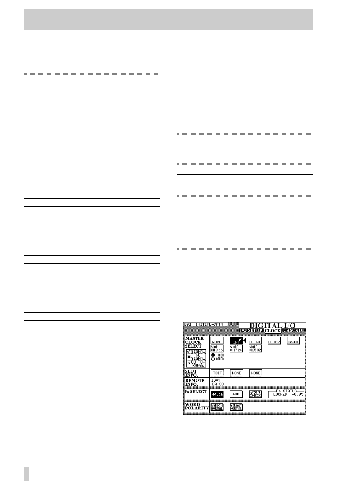
The Cascade setup (accessed through the
DIGITAL I/O key) is described in 11, “Cascade”, the Solo setup in 5, “Monitoring”, and
the Surround setup in 6, “Surround modes”.
3.1 I/O setup
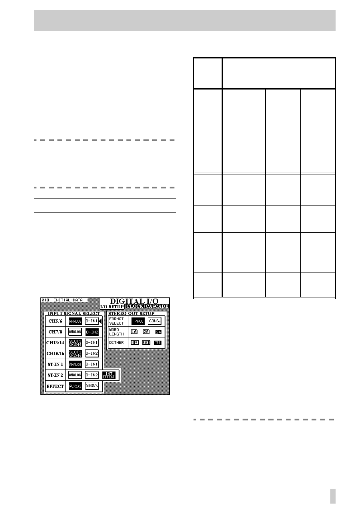
1
With the
DIGITAL I/O
appears.
This screen allows the selection and assignment of
the digital inputs to channels. Note that the same digital input may appear as an input option for more
than one pair of channels. If a digital input is selected
as the source of more than one pair of channels, it
will appear at all these channels simultaneously.
SHIFT
indicator off, press the
key
until the screen below
[5]
The options available are:
Input
channels
5 & 6 Analog (integral
analog channels 5 and 6)
7 & 8 Analog (integral
analog channels 7 and 8)
13 & 14 Slot 1 CH13-14
(channels 7 and
8 of the card in
slot 1)
15 & 16 Slot 1 CH15–16)
channels 7 and
8 of the card in
slot 1)
ST-IN 1 ANALOG (inte-
gral stereo
inputs)
ST-IN 2 ANALOG (inte-
gral stereo analog inputs
a
EFFECT
AUX1/2 (Aux
busses 1 and 2)
Available sources
D-IN1 (XLRtype)
D-IN2 (RCA) —
D-IN1 (XLRtype9
D-IN2 (RCA) —
D-IN1 (XLRtype)
D-IN2 (RCA) INT
AUX5/6
(Aux busses 5 and 6)
—
—
—
EFFECT
(internal
effect processor)
—
a. The source of the internal effect processor
input
3.1.1STEREO OUT settings
In addition to these input sources, changes to parameters affecting the digital output of the
OUT
can be made.
Firstly , the
either professional (
(
CONS.
STEREO OUT
PRO.
) format.
can be selected as being in
) or consumer
Changing the setting made here will also affect the
format of the output from any IF-AE4000 interface
cards fitted in the expansion slots.
NOTE
The Consumer format, when output from the
unbalanced RCA STEREO OUT jack, corresponds to the IEC61958 (SPDIF) format.
STEREO
3–1
Page 19
3 - System setup—CLOCK setup
If the Professional format is selected, the
resulting data output from the RCA STEREO
OUT jack will probably be unusable by most
domestic equipment.
3.1.2Consumer options
If the chosen output is Consumer, hold down the
SHIFT
key and press the right switch of POD 4 to
change the SCMS (copy-protect) settings between
FREE
one-generation) and
(SCMS disabled),
NO COPY
ONCE
An appropriate message will appear on screen, and
these settings are stored in memory.
In addition, the category of consumer audio can be
set using the
SHIFT
key along with the left switch of
POD 4 to cycle through the following values:
General
CD
LD
MD
CODEC
MIXER
SRC
SAMPLER
DAT
DVTR
DCC
TV-J
TV-EUR
TV-USA
TV
Synth
Microphone
Pro A/D
A/D
RAM
General
CD
Laser (usually disc)
MD
PCM Codec
a
Mixer
SRC (Sample Rate Converter)
Sampler
DA T
DVTR
DCC
Japanese broadcast digital
European broadcast digital
American broadcast digital
Broadcast digital
Synthesizer
Microphone
Copy-free A/D converter
A/D converter
Solid state reproducer
(standard SCMS
((copy-prohibit).
If the selected word length is less than 24 bits, you
may choose to dither the resulting output. Dithering
helps to reduce quantization noise, but results in a
slightly lower signal-to-noise ratio. Choose either
OFF
, rectangular (
RECT
) or triangular (
TRI
)
dithering. The shape names refer to the probability
distribution of the noise which is used in the dithering process.
Typically, triangular dithering gives better quantization noise reduction than rectangular, but the signalto-noise ratio is not as good.
NOTE
The word length from the output busses is
always set to 24 bits.
3.2 CLOCK setup
WARNING
There should be one, and only one, word
clock source in a digital audio setup. Multiple
word clocks in a setup may result in noise
which can damage monitoring equipment
(speakers and amplifiers).
The word clock source is selected in the following
way:
With the
1
DIGITAL I/O
shown (note that the exact screen may differ
from that shown here, depending on the
number and the type of the interface cards
fitted in the expansion slots):
indicator unlit, press the
SHIFT
key until the screen below is
a. TM-D4000 default setting
This allows the TM-D4000 to pose as an alternative
audio source, for instance if an MD deck can only
accept signals from a CD or another MD deck, or in a
broadcast situation, a certain category may be necessary for use with other equipment.
If an attempt is made to set the category with the Professional format setting, an error message, “No Category for AES/EBU” will appear on screen.
3.1.3Word length and dithering
The word length can be selected as being either
20
or
24
bits in length.
16
3–2
Move the cursor to the box which contains
2
,
the description of the desired clock source.
Page 20
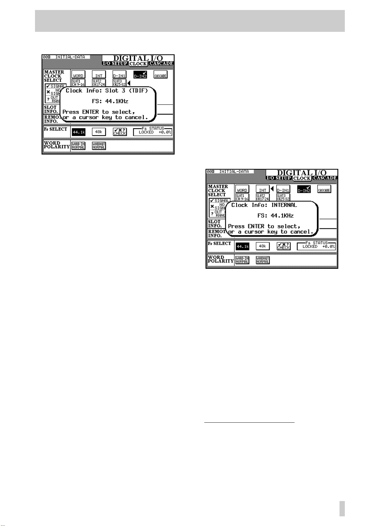
3 - System setup—CLOCK setup
3
Select the clock source by pressing
The popup panel provides information about
the potential clock source. Press
select this source, or any one of the cursor
keys to dismiss the popup panel, and select
another source.
In the case of an IF-AE4000 (AES/EBU
interface card), there are four different
sources (the four AES/EBU inputs) which
may be selected as the word clock source for
the TM-D4000.
ENTER
ENTER
to
.
ADAT is to be a word clock slave, especially
if more than one AD AT is connected. See also
9.4.4, “ADAT devices”.
If more than one IF-LP4000 card is fitted,
there are three choices for each card, regardless of the actual connection of the ADAT
units to the TM-D4000. The last on-screen
button pressed (on any of the IF-LP4000
options) then determines the status of the
first ADAT in the chain.
4
If the clock source has been selected as INT,
the clock rate (sampling frequency) can be
selected. In all other cases, the sampling frequency is fixed and cannot be changed.
1
If the TM-D4000 has been cascaded from
another unit, the clock source is set as
CASCADE
“head” of the cascade chain can select the
clock from any source.
In the case of an IF-TD4000 (TDIF-1 interface card), the device attached to the card
source is shown as either a
DTRS recorder) or
of recorder connected through the TDIF-1
interface). If the indicator shows DA88, then
I/O data is truncated to 16 bits, otherwise I/O
is carried out at 24 bits.
In the case of an IF-LP4000 (ADAT “lightpipe” interface card), there are three
options:
than one IF-LP4000 is fitted, changing the
setting for one card will change the settings
for all the rest. The
ADAT to act as the clock master (this is not a
recommended setting). If
the ADAT receives its clock through the
SYNC cable, and if DIGI is selected, the
optical connection is used as the clock source
to the ADAT. We strongly suggest that
SYNC is used, rather than DIGI, if the
and cannot be changed. The
DA88 ( DA-88
OTHER (another type
INT, SYNC or DIGI. If more
INT setting allows the
SYNC is selected,
3.2.1Selecting clock frequencies
Word clock sources, except for WORD and ADAT
sources, include information regarding their sampling frequencies. If either
selected as a clock source, the procedure below
should be followed:
1
Decide what sampling frequency the project
will use.
2
Select INT as the clock source (this is a
temporary measure), and select the fre-
quency.
3
Select the final clock source (WORD or
ADAT). The TM-D4000 sampling fre-
quency will now match the incoming word
clock.
1. Note that the other ADAT units, “daisychained” to the first ADAT unit in the chain
with SYNC connections, will be automatically
set to take their clock from the SYNC connector, and their IDs will also be set automatically, regardless of setting made here.
WORD or ADAT is
3–3
Page 21
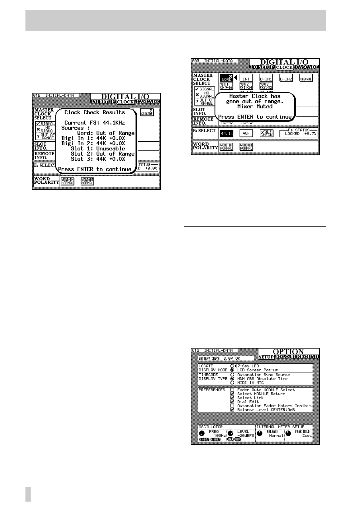
3 - System setup—Option setup
3.2.2Clock check
The status of all possible clock sources currently
connected to the TM-D4000 can be checked by moving the cursor to the
ENTER. The console will mute, and a list of av ailable
clock sources will be shown.
ENTER to continue operations.
Press
CHECK box and pressing
3.2.3Clock settings (other)
indicator will flash, and a message will appear on the
display:
The TM-D4000 will report the out-of-range clock
frequency at a range of ±9.9% relative to the stated
frequency, but will mute at 7.0% or over.
Press the
change to the
condition (by selecting another clock source, or by
re-selecting the clock if it has come back into range).
ENTER key to dismiss the popup message,
CLOCK screen, and correct the error
The Fs STATUS box shows the status of the
currently selected clock source.
WORD POLARITY settings allow either
The
incoming or outgoing word clock information to be
inverted (
because some units either transmit or expect to
receive such signals in this inverted format.
REVERSE) relative to normal. This is
3.2.4Clock tolerance
When setting the clock, the sampling frequency
received can be ±6% of the stated nominal value.
When in use, the frequency can be ±7% of the stated
value. This allows a digital device which has a
varispeed feature to be used as the word clock source
for the TM-D4000.
If the selected clock source goes out of range, the
TM-D4000 will mute, the currently-selected clock
3.3 Option setup
In unshifted mode, this key is used to show the
OPTION screens. There are three of these
screens:
and they are accessed by repeated presses of the
OPTION key.
The solo operations are explained in 4, “Module
operations”, and the surround operations in 6, “Surround modes”.
The
(as well as displaying the current battery voltage,
used to power the memory holding library entries,
etc.) as shown and described below:
SETUP, SOLO and SURROUND,
SETUP screen provides the following options
3–4
These settings are generally made using the cursor
keys to move the cursor to the parameter to be
Page 22

3 - System setup—Option setup
changed, and the ENTER key is then used to make
the setting.
3.3.1Location display mode
When using the TM-D4000’s location facilities to
control an external device, the value of the location
points (
be displayed either on the main time counter (
Seg LED) or as a “pop-up” panel on the main
display screen (
LOCATE DISPLAY MODE) can
7-
LCD Screen Pop-up).
These options are mutually exclusive, i.e. you can
only choose one.
3.3.2Timecode source
The timecode displayed on the time counter can be
taken from the timecode source used for automation
timing (
Source), directly from a DTRS recorder
through the
Absolute Time) or received at the
MIDI IN terminal as MIDI timecode (MIDI
IN MTC [MIDI Time Code]). This
Automation Sync
REMOTE IN terminal (MDR ABS
timecode source is also used when controlling external devices (see 9, “Machine Control”). Again, only
one of these options can be selected.
3.3.3Preferences
The PREFERENCES are as follows: Fader
Auto MODULE Select, Select
MODULE Return, Select Link
and
Dial Edit, Automation
Fader Motors Inhibit and
Balance Level CENTER 0dB.
Any number of these preferences can be selected, as
indicated by a check mark in the checkboxes (✔).
3.3.4Fader select
When checked, and the MODULE screen is currently displayed this option allows a module to be
selected whenever its fader is moved, in addition to
the usual method of pressing the
SEL key.
3.3.5Select MODULE return
When checked, this option allows the MODULE
screen of the appropriate module to appear (even if a
MODULE screen is not currently displayed) if the
SEL key of the module is pressed and held for about
two seconds.
3.3.6Select link
When checked, this option allows the stereo linking
of two adjacent modules (provided the left module is
odd-numbered) by pressing and holding the
SEL key
of one module and pressing the
SEL key of the other .
See 4.2.2, “Using the SEL keys to link channels”.
3.3.7Dial edit
When checked, this option allows the JOG dial to be
used as a data entry dial for the on-screen control
pointed to by the triangular cursor, which is usually
controlled by a POD knob. In effect, this provides
another POD. In addition to this option being
checked, the
when using the
JOG/SHUTTLE indicator must be off
JOG dial in this way, to prevent the
JOG dial being used as a transport control.
3.3.8Automation fader inhibit
The Automation Fader Motors
Inhibit setting allows the motorization of the
faders to be turned off or on for automation replay
(Read) purposes. See 2.4.1, “Turning fader motors on
and off”.
3.3.9Balance level
When two channels are linked together as a stereo
pair, the pan controls change to a balance control, as
mentioned earlier. In the center position, the level
may either be set to
0dB (checked) or a 3 dB cut
(unchecked).
3.3.10Oscillator
The integral line-up oscillator can be turned using the
left switch of POD 2 and the frequency adjusted with
the POD 1 control. It can be assigned to either the
left or right main output buss, (
R buss), Both of these, or neither using the
L Buss,
switches of POD 1. The left busses are the odd-numbered output busses (1, 3, 5, 7) and the left channel of
the stereo output buss. The right busses are the evennumbered output busses (2, 4, 6, 8) and the right
channel of the stereo output buss.
The POD 1 rotary control is used to change the level
of the oscillator, relative to full-scale.
3.3.11Meter ballistics
The release rate (“fall time”) and peak hold time of
the meters and can be adjusted using the knobs of
PODs 3 and 4.
The release rate can be set to
or
Slow.
The hold time can be set to
2sec, 4sec, 8sec or ß . The final (infinity)
setting will hold the peak value until a new setting is
made (or the TM-D4000 is turned off!).
Fast, Normal
0sec, 1sec,
3–5
Page 23
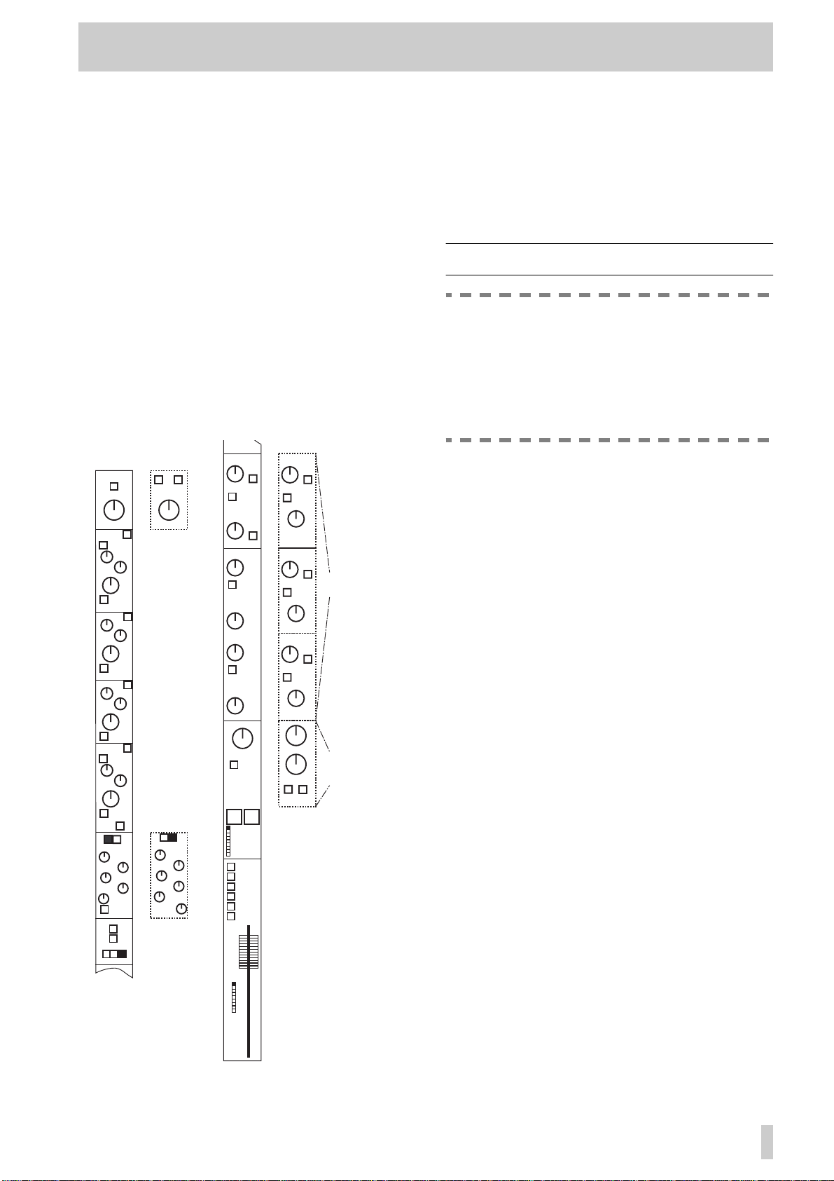
4 - Module operations
The input modules of the TM-D4000 are of two
types: mono input and stereo inputs. There is no difference between a “tape return” channel, an “effects
return” and an input channel—all modules are
equipped with the same features.
The digital parts of the mono input modules are identical, regardless of what interface card is fitted. The
only difference between mono modules is that modules 1 through 8 use the integral mic amplifiers and
A/D convertors. These analog features (MIC/LINE
switch, phantom powering, analog pad and gain, etc.)
work in an identical way to similar features on a conventional analog console. If you are unsure about the
operation of these items, consult 13, “Rear panel &
connections”.
If the digital functions of the modules were “converted” to analog controls, a module would look similar to the following:
AUX 1
PHASE (Φ)
PAD
ON
HI
SHELF
F
Q
LPF
HI-MID
ON
F
Q
NOTCH
LO-MID
ON
F
Q
NOTCH
ON
LO
SHELF
F
Q
HPF
EQ
COMP/GATE
ATT
REL
THRSH
RATIO
OUT GAIN
AUTO
DYNAMICS
ON/OFF
TRIGGER
L R BOTH
L R
PHASE (Φ)
PAD
Stereo
inputs &
stereo
linked
pairs
G
G
G
G
COMP/GATE
THRSH
RANGE
HYST
ATT
HOLD
DECAY
Gate
selected
LINK
as
dynamic
processor
LINK
LINK
LINK
GANG*
PRE/POST
AUX 2
PRE/POST
AUX 3
AUX 4
AUX 5
AUX 6
PAN
OFF
1
2
3
4
5
6
7
8
1-2
3-4
5-6
7-8
L-R ST
DIRECT
OUT
FADER
GROUP
OFF
PAN
CUT
GROUP
1
2
3
4
5
6
7
8
*the GANG control is only available on odd-numbered modules
AUX 1-2
PRE/POST
UNLINK
PAN
AUX 3-4
PRE/POST
UNLINK
PAN
AUX 3-4
PRE/POST
UNLINK
PAN
IMAGE
BALANCE
LR
MONO
SOLOCUT
Stereo
linked Aux
sends
Stereo
inputs &
stereo linked
pairs
Dashed lines indicate options (e.g. the dynamics processor selected for each module can be a compressor/
limiter or a gate, but not both). Aux sends can be
optionally linked, providing a PAN control. When
channels are linked together in a stereo pair (see 4.2,
“Stereo linking”), the PAN controls are replaced by
an IMAGE control and a BALANCE control.
4.1 Module features and control
NOTE
This section contains the instructions for the
everyday module operations, as described
below. You should at least make yourself
familiar with the contents of this section, so
that you know which parts to use for reference
if you need information.
Very briefly, the typical signal path is:
• phase (4.8, “Pad and phase( Φ )”
• digital trim (4.8, “Pad and phase( Φ )”)
• 4-band EQ (4.3, “Equalization”)
• dynamics processor (comp/limiter or gate) (4.6,
“Dynamics processor settings”)
• fader (self-explanatory—for details of fader grouping, see 4.9, “Fader and cut groups”)
• Aux sends (4.5, “Aux sends”
• cut and solo (cut groups are described in 4.9,
“Fader and cut groups”, solo modes are described
in 5, “Monitoring”)
• panpot (4.7, “Pan and balance”)
• channel-to-buss assignment (4.4, “Channel-to-buss
assignments”)
4.1.1Stereo out module
This module includes 4-band EQ facilities and a
dynamics processor (identical to those provided on
the other modules).
4.1.2Control of module parameters
In many instances, there may be more than one way
of controlling module parameters: e.g. from the
MODULE
parameters for a single module (or linked pair) and
from a dedicated “global” screen, allowing the
adjustment of a single parameter for many modules.
These are described in 2.3.4, “One channel or one
parameter?”. In this section, the appropriate way(s)
of working are described for each parameter.
screen, allowing the control of many
4–1
Page 24
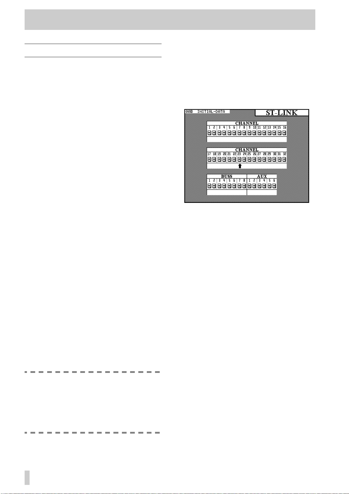
4 - Module operations—Stereo linking
4.2 Stereo linking
In unshifted mode, the
GROUPING/ST LINK
allows the linking of channels as stereo pairs.
Only adjacent channels can be linked into stereo
pairs, and the lower channel must be odd-numbered.
In other words, while it is possible to link channels 1
and 2, it is not possible to link channels 1 and 3, nor
is it possible to link channels 2 and 3.
Stereo linked channels allow the simultaneous setting
and linking of the following module parameters:
• Input source
• Digital pad setting
• EQ settings
• Aux 1–6 send levels, on/off status and pre/post
status
• Dynamics processor settings
• Logical fader level
•
CUT
switch status
SOLO
•
switch status
• Buss assignment
• Fader group and cut group assignments
• Automation mode settings.
In addition to the stereo linking of channels, the TMD4000 also allows the stereo linking of output busses
1 through 8, and Aux send busses 1 through 6. Again,
only adjacent busses may be linked, and the lower
buss of each buss pair must be odd-numbered.
When a pair of output busses is linked, the buss send
levels and delay settings are linked.
When a pair of Aux sends is linked, the send levels
are linked.
In cases where pan controls were previously available (channels), the pan controls are changed to balance controls and an image width control is added.
When channels are linked, the pan “gang” feature is
no longer available.
key
4.2.1Using the ST LINK key to link channels
T o mak e a stereo link between two adjacent channels
or busses, make sure the
press the
ST LINK
Use the cursor keys or the
sor (upward-pointing arrow—
SHIFT
indicator is off, and
key to show the screen below.
dial to move the cur-
JOG
ø
) to the pair of chan-
nels or busses whose link status is to be changed.
Press the
ENTER
channel status (
LINK
) of the channels or busses.
key to change between separate
) and stereo linked status (
ªº
ST
4.2.2Using the SEL keys to link channels
See 3.3.6, “Select link” for details of the
Link
parameter. When this is set on, the
of channels may be used to create and remove stereo
links, rather than the screen described above.
Note that the
when the
GROUPING
keys have a different function
SEL
screen, described in 4.9,
“Fader and cut groups”, is showing, and therefore
stereo linking and unlinking cannot be carried out at
that time.
Pressing and holding the
SEL
key of one of a valid
pair of channels and busses and then pressing the
SEL
key of the other member of the pair will bring
up a pop-up panel asking for confirmation to form
the stereo link between the two channels or busses.
Press
ENTER
to confirm, or a cursor key to cancel.
Select
keys
SEL
NOTE
When a pair of channels or busses is linked, if
the physical faders are not in identical positions before the link process, the “child” fader
of the pair will rise to meet the other “parent”
fader. This may cause a sudden rise in monitoring, etc. levels.
4–2
If the two channels or busses already form a stereo
link, this procedure will bring up a pop-up panel asking for confirmation to break the link. Press
ENTER
to confirm, or a cursor key to cancel.
The status of stereo links between channels and bus-
ses can be verified at any time, using the screen
described above.
Page 25
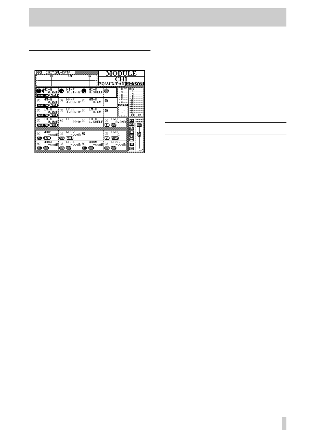
4.3 Equalization
4 - Module operations—Equalization
PODs will change the shape of the curve. When the
EQ is brought back, these changes will take effect.
The first three PODs in the first four POD rows of the
MODULE
screen control the equalization.
As the equalization settings are changed, the graphical representation of the EQ response also changes.
The four EQ bands are named
LM
mid),
LO
(low-mid) and
bands differ from the other two, as explained
HI
LO
(low). The
(high),
HM
HI
(high-
and
below.
The gain of the bands is between
-15 dB
in 62 steps.
+15dB
and
However, the high and low bands can be set to act as
lowpass and highpass filters, respectively, by turning
the gain to below the minimum
If the gain is turned below
-15dB
-15dB
setting.
on the HM and
LM bands, they change to notch-type filters.
Each of the four EQ bands covers the same frequency
range:
32Hz
19kHz
to
, selectable over a 112-
step range using POD 2.
The Q of each band (the frequency range over which
it operates) can be set from 8.65 to 0.27 in 25 steps.
The high and low bands can be set to provide shelving EQ, as opposed to peaking-type EQ.
Each band can be turned on and off using the left
switch of POD 1.
The gain of each band can be flattened using the right
switch of POD 1.
In order to bypass the equalization circuit for the
key to the right of the
module completely, the
EQ
display screen should be pressed. When the EQ is
bypassed, the response curve at the top of the display
is “grayed out” to show that EQ settings have no
audible effect, but making adjustments using the
When two channels have been linked into a stereo
pair, or when one of the two stereo inputs is selected,
the changes made to the equalization affect both
channels equally.
EQ settings, once made, may be stored in the EQ
library for further recall. The way in which this is
done is explained in the section of this manual dealing with the TM-D4000 libraries (8, “Library functions”).
4.4 Channel-to-buss assignments
There are two ways of assigning channels to the eight
output busses, the stereo busses, or for direct output:
using the dedicated
MODULE
screen.
ASSIGN
4.4.1Using the MODULE screen for buss assignment
The status of the keys to the right of the display
screen are shown:
reo assignment keys, and the direct out status (for
input channels 1 through 16).
The function of the
explained in the appropriate places (4.3, “Equalization” and 4.6, “Dynamics processor settings”).
The channel can be assigned to any combination of
the eight output busses and the stereo output buss.
Busses are selected in pairs (1–2, 3–4, 5–6, 7–8).
As with most analog consoles when a buss pair is
selected, the odd-numbered buss of the pair corresponds to a hard left pan, and the even-numbered
buss corresponds to a hard right pan. Anything in
between will balance the channel signal proportionately between the two busses.
Input channels 1 through 16 (the integral analog
inputs and the inputs of slot 1) can also be assigned
as direct outs (
DIR
They are sent from the outputs which correspond to
the input channel number, plus 16. In other words,
input channel 1, when selected for direct out, is output from channel 17 (the first output channel of slot
2), channel 9 is output from channel 25 (the first out-
put channel of slot 3), etc. If slots 2 and 3 are not fitted with interface cards, the
no effect.
,
EQ
EQ
on this screen).
key or from the
DYNAMICS
and
DYNAMICS
DIRECT
, the buss and ste-
keys are
key will have
4–3
Page 26
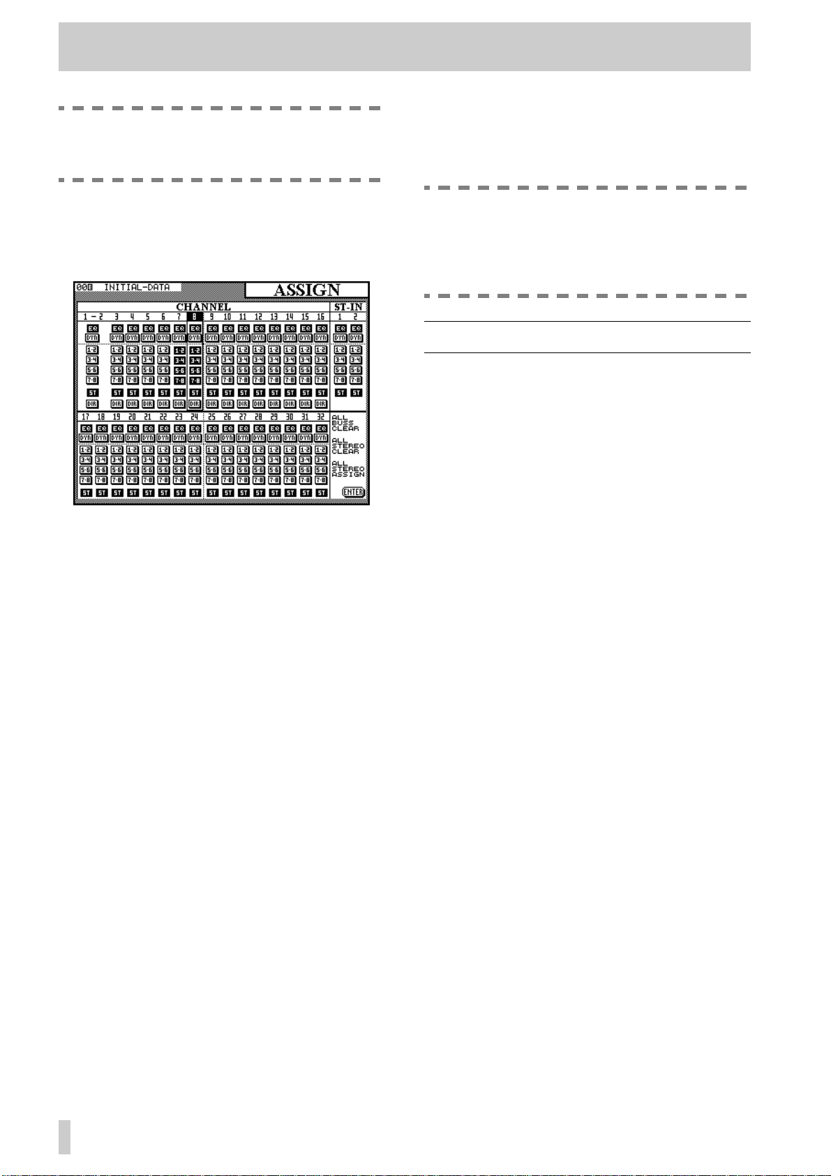
4 - Module operations—Aux sends
NOTE
The direct out setting is availab le f or channels
1 through 16 only.
The direct out of channels 1 through 16 can also be
set in this screen (there are no on-screen representations of the direct out setting for channels 17 through
32, as this is not possible).
4.4.2Using the ASSIGN key for buss assignment
Press the
assignment screen.
The cursor keys are used to move the cursor to a particular channel and highlight the channel’s number at
the top of the column.
Alternatively, the channel’s
select a channel.
When a channel has been highlighted on this screen,
pressing any of the following keys to the right of the
display screen will change the assignment status of
the selected channel:
,
6
BUSS 7-8
As with most analog consoles when a buss pair is
selected, the odd-numbered buss of the pair corresponds to a hard left pan, and the even-numbered
buss corresponds to a hard right pan. Anything in
between will balance the channel signal proportionately between the two busses.
In addition, the
bypass the equalization and the dynamics processor
for each channel, respectively.
There are three “global” on-screen buttons. The first
of these (
clear all buss (but not stereo) assignments. This may
be used, either together with or independently from
the last (
starting the mixdown in a multitrack recording
session.
The second on-screen button, ALL STEREO
CLEAR, clears all channel-to-stereo assignments.
ASSIGN
ALL BUSS CLEAR) is used to
ALL STEREO ASSIGN) when
and
EQ
key
[10]
BUSS 1-2
STEREO
DYN
and
to bring up the channel
SEL
key may be used to
,
BUSS 3-4
.
keys can be used to
,
BUSS 5-
NOTE
When channels 1 through 16 are set to direct
out, the signal appears in the output channel
corresponding to the number of the input
channel plus 16, as described above.
4.5 Aux sends
The MODULE screen can also be used to set the
Aux send levels for a channel or pair of stereo linked
channels. In addition, there are six dedicated
keys which allow the viewing and setting of the six
Aux send levels of many channels from one screen.
4.5.1Using the MODULE screen to set send levels
The level of the signals sent from the channel to the
six Aux sends are set and displayed on the bottom
two rows of the
screen.
In an identical fashion to the dedicated Aux screens,
the levels of the Aux sends can be set from -ß dB to
10.0dB.
The left switches of the Aux PODs are used to turn
the module’s Aux sends on and off.
Aux sends 1 and 2 can be selected as pre- or postfader, using the right switches of PODs 1 and 2
respectively.
When two modules have been linked into a stereo
pair, or one of the two stereo inputs is selected, the
Aux send levels apply to both channels in the pair.
When two Aux b usses ha ve been link ed together into
a stereo pair, the level control of the first (odd-numbered) Aux b uss is replaced by a pan control. The left
switch of the corresponding POD becomes a centering switch.
MODULE EQ/AUX/PAN
4.5.2Using AUX keys to set send levels
When one of the AUX keys is pressed and the Aux
buss selected has not been made into a stereo linked
pair with the adjacent Aux buss, two screens are
available, each controlling 16 input channels. The
AUX
4–4
Page 27
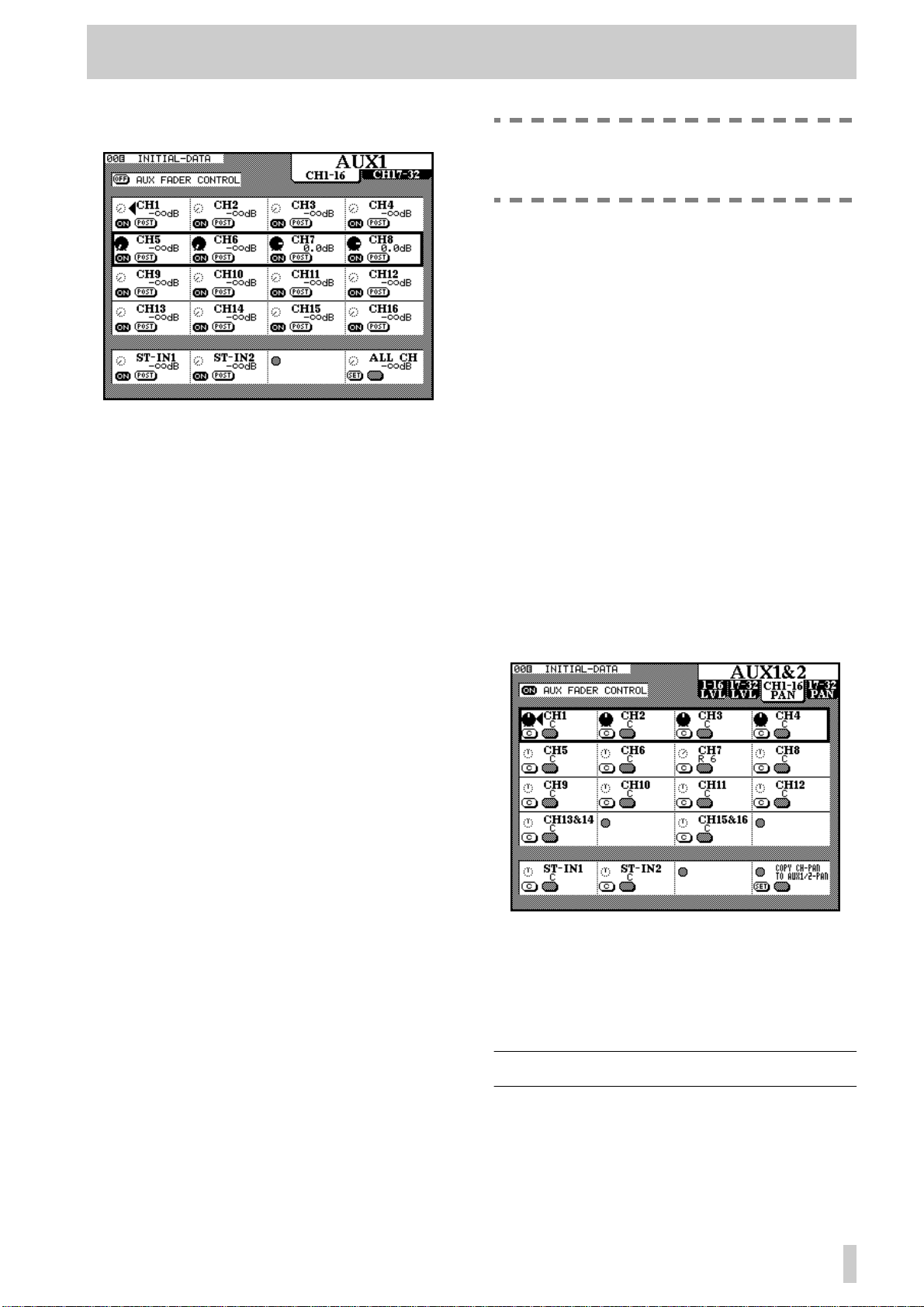
4 - Module operations—Dynamics processor settings
first screen controls channels 1–16 and the second
controls channels 17–32.
Use the POD ROW CURSOR controls to move the
“box” up and down, highlighting the channels which
are to be edited.
The POD rotary controls adjust the level of the signal
sent to the Aux buss.
This level can be adjusted from
tive to nominal) to
in 128 steps.
The left POD switches control whether the Aux send
signal from the selected channel is on or off.
For Aux busses 1 and 2, the right POD switch functions as a pre/post selector, allo wing the pickoff point
for the Aux send to be pre-fader or post-fader.
-¢dB (minus infinity–full cut)
+10.0dB (rela-
NOTE
This is the only time that the
ST IN
faders
change function.
If two channels have been linked as a stereo pair (see
4.2, “Stereo linking”), only the left POD of the pair is
active.
Stereo linking and AUX sends : If two Aux
sends have been linked together as a stereo pair , there
are now four screens available when an
pressed.
As well as the level screens for the two sets of 16
channels (identical to the one described above), there
are also two pan screens; one for each set of 16
channels.
In these screens, the POD rotary controls are used to
adjust the relative level of the signal sent to the two
linked Aux busses.
The left switch of the PODs is used to center the pan
control for the channel.
In the case of a stereo linked pair of channels, the left
POD only is active. The pan control changes to a balance control. This can be centered using the left POD
switch in the same way as a mono channel.
AUX key is
The pre-fader point is also before the cut and solo
switches, as well as before the pan.
The bottom POD row of the screen provides controls
for the two stereo inputs, as well as a global control
control. Turn the fourth POD’s knob to select
between
OFF, AUX ON and (for Aux sends 1 and 2 only)
PRE and POST. Use the left POD switch to
SET the value selected using the knob for all
channels.
-¢dB (full cut), 0dB (nominal), AUX
AUX Fader control : There is also one impor-
tant on-screen button at the top of the screen: the
AUX FADER CONTROL button.
When this option is selected using the cursor and
ENTER keys, the faders will move to match the Aux
send levels of the currently-selected Aux buss, and
the currently-selected
(
[3]) will flash to show that the faders are no longer
controlling channel and module levels.
The PODs are also active, and moving a POD knob
will also move the appropriate fader to reflect the
new level.
LAYER STATUS indicator
The left switch of POD 4 in the last row is used to
copy the channel pan settings of all channels to the
pan settings for the selected Aux send pair. In this
way, the main “buss” image of the channels is preserved in the Aux sends.
4.6 Dynamics processor settings
These settings are accessed by pressing the MODULE
key for the selected channel until the
screen is shown, or alternatively by pressing the
EQ/DYN
4–5
Page 28
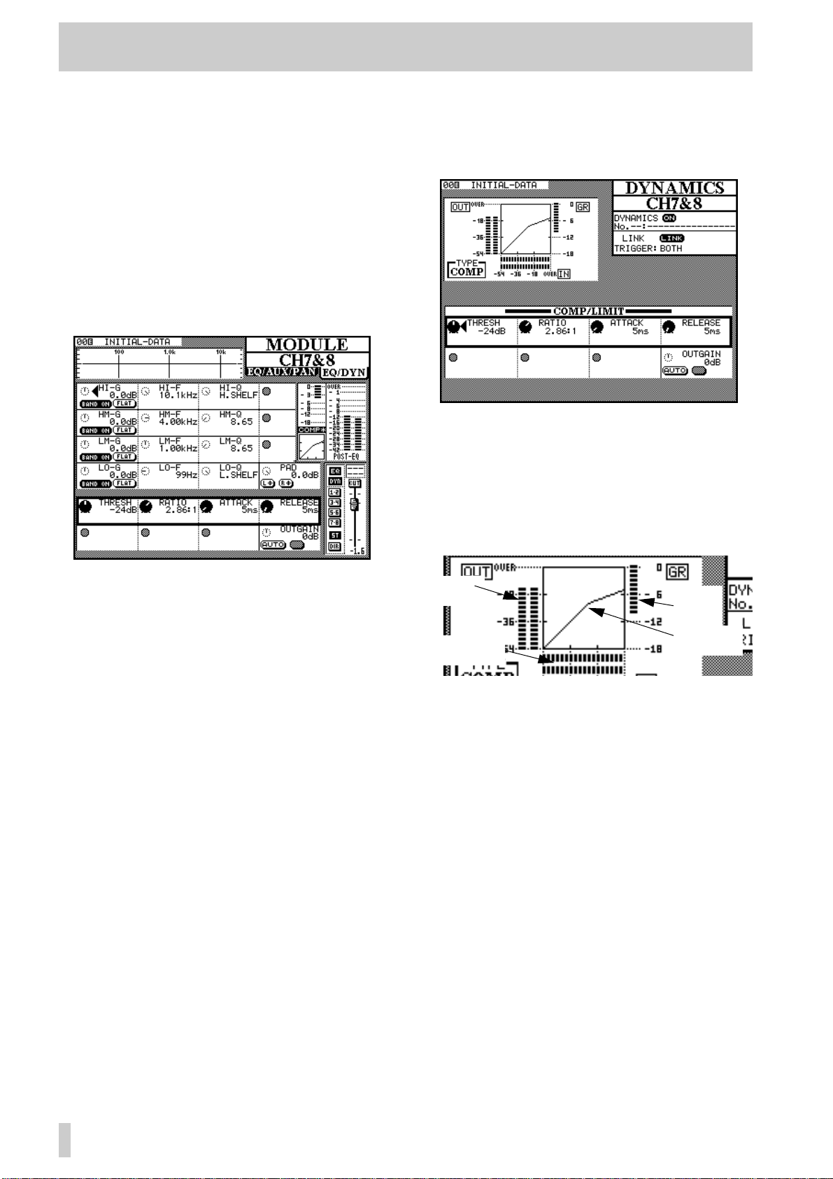
4 - Module operations—Dynamics processor settings
DYNAMICS key to recall the DYNAMICS screen
for the selected module.
4.6.1Assigning a processor to a module
This is described in full in 8.2.2, “Recalling a library
entry”. Briefly, the module is selected, the dynamics
processor library screen is entered, and the desired
processor settings are recalled from the library.
4.6.2Using the MODULE key to make dynamics processor settings
The equalization controls on this screen are identical
to those on the other
MODULE screen.
4.6.3Using the DYNAMICS key to make dynamics processor settings
With the desired channel selected, press the mixer
DYNAMICS key (not the library DYNAMICS key).
The information at the upper left of the screen
includes:
• The dynamics processor’s gain reduction meter
• A graphical representation of the dynamics proces-
sor’s gain structure. An example of the way a pair
of stereo linked processors are shown on screen is
given here:
However, the two lowest POD rows are used to control the dynamics processor. The e xact assignment of
the PODs to controls depends on whether a gate or a
compressor (shown on the small on-screen level diagram as
GATE or COMP) has been recalled from
the library into this channel, as described below.
To enable and disable the selected channel’s dynam-
ics processor, use the DYNAMICS key to the right of
the display screen. The on-screen
DYN indicator in
the “button strip” at the lower left of the screen
changes to reflect the on/off status.
Stereo linked channels and stereo inputs may share
the same dynamics processor settings. However, see
the explanation of the
DYNAMICS key immediately
following this, for further information regarding stereo linking of dynamics processors.
Output
levels
Input levels
Gain
reduction
Compressor
“knee”
4.6.4Compressor/limiter settings
Both the MODULE and DYNAMICS screens
allow the same parameters to be set.
• Threshold (
knob, and variable from
1 dB steps.
• Compression ratio (
POD 2 knob, and variable from
(infinite compression) in 21 steps.
• Attack time (
3 knob, and variable from
1ms steps.
• Release time (
POD 4 knob, and variable from
in 100 steps.
• Output gain (
POD 4 knob on the last row. Variable from
-24dB to +24dB in 1 dB steps.
THRESH), controlled by the POD 1
-48dB to 0dB in 49
RATIO), controlled by the
1:1 to ß:1
ATTACK), controlled by the POD
0ms to 125ms in
RELEASE), controlled by the
5ms to 5.0s
OUTGAIN), controlled by the
4–6
Page 29

4 - Module operations—Pan and balance
• Auto make-up (AUTO), controlled by the left
switch of POD 4 below the output gain. This is
used, together with the output gain setting for automatic optimum level control if the compression settings have resulted in gain reduction.
4.6.5Gate settings
Both the MODULE and DYNAMICS screens
allow the same parameters to be set.
• Threshold (
knob, allows the setting of the threshold at which
the gate will open. Variable from
0dB in 1 dB steps.
• Range (
sets the gate range, from
steps.
• Hysteresis (
knob, from
• Gate attack time (
POD 1 knob on the last row. Variable from
to
125ms in 1 ms steps.
• Gate hold time (
2 knob on the last row. Variable from
990ms in 100 steps.
• Gate decay time (
POD 3 knob on the last row . V ariable from
to
5.0s in 100 steps.
4.6.6Linked channels
LINK allows the linking of two processors
assigned to two adjacent channels (the “left” channel
of the pair must be odd-numbered).
This link is automatically made, and cannot be
turned off, when two modules have been stereo
linked (or for the stereo inputs or the stereo out).
Trigger source (TRIGGER) is only valid when
two processors are linked. This option (selected
using the
gering for both processors to be initiated by
(left channel),
(both channels act as triggers—in other words, the
first channel to be triggered will automatically activate the second channel’s processor).
The two ST IN channels and the stereo out
buss do not allow trigger selection, and are
fixed at the
THRESH), controlled by the POD 1
-80dB to
RANGE), controlled by the POD 2 knob,
0dB to 60dB in 1dB
HYST), controlled by the POD 3
0dB to 24dB in 1dB steps.
ATTACK), controlled by the
0ms
HOLD), controlled by the POD
0ms to
DECAY), controlled by the
50ms
ENTER key or JOG dial) allows the trig-
L-ch
R-ch (right channel) or BOTH
NOTE
BOTH
setting.
4.7 Pan and balance
As well as using the MODULE screen to adjust the
pan of a module (or the balance of a stereo pair of
modules), there is a dedicated
allowing the viewing and setting of many modules
simultaneously.
4.7.1Using the MODULE key to set pan and balance
Pan and balance controls are only available in the
EQ/AUX/PAN MODULE screen, not the
EQ/DYN module screen.
Mono modules : The fourth POD rotary control
on the fifth row is a pan control, when the module is a
mono module.
The pan settings are L45 (hard left), through C
(center) to
R45 (hard right).
The left switch of this POD is a centering switch.
For odd-numbered channels only, the right switch of
this POD is a gang switch, allowing this pan control
to be ganged with the pan control of the next channel.
Stereo modules : When two channels ha ve been
linked into a stereo pair, or when one of the stereo
inputs is selected, the pan control changes to a balance control.
The left switch of the POD is a centering switch.
The third POD becomes an “image” control, which
determines the width of the stereo image produced
by the two channels. T urning the knob to the “center”
allows “pinpointing” of the image (
full width (
full width, with the positions of the two linked channels reversed with respect to normal (
fully clockwise). Intermediate positions are represented as percentage figures preceded by
reo) or
immediately after
immediately after
The switches of the third POD allow either the left or
the right channel of the pair to be selected as a mono
source (the image control is then disabled).
If a surround mode, rather than the stereo mode, has
been selected, surround positioning control is not
possible from the
cated
modes” for details.
STEREO, fully counterclockwise) or
REV (reverse), with ST 98% following
STEREO, and REV 98%
REVERSE.
MODULE screen. Use the dedi-
PAN/BAL key instead. See 6, “Surround
PAN/BAL screen,
L+Rmono),
REVERSE,
ST (ste-
4–7
Page 30
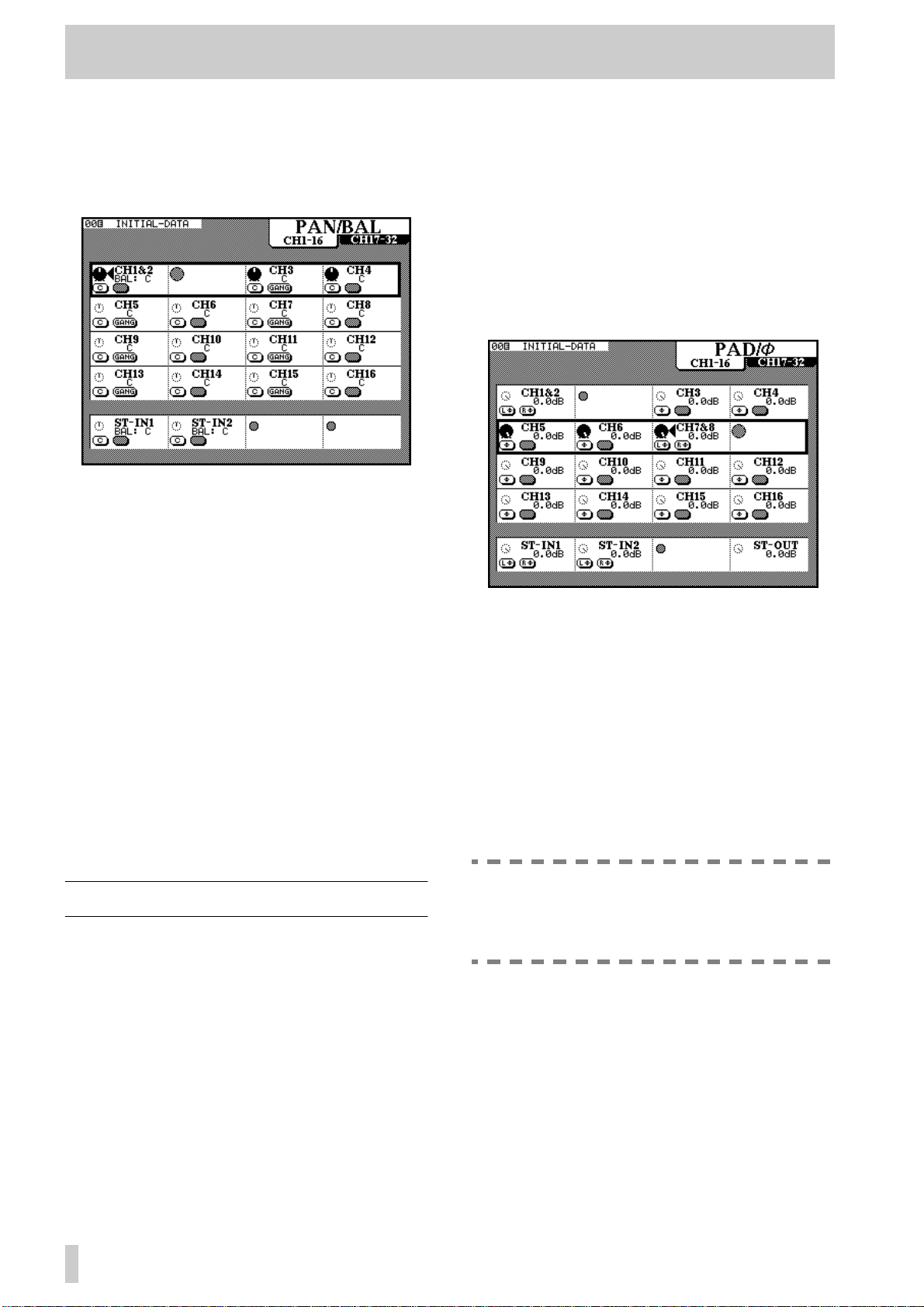
4 - Module operations—Pad and phase(Φ)
4.7.2Using the PAN/BAL key
Pressing the P AN/B AL k ey brings up a display screen
allowing the viewing and setting of a number of the
pan and balance parameters for a number of different
modules:
There are two screens, the first for the input modules
1 through 16, and the second for input modules 17
through 32. The stereo inputs are visible and their
parameters may be adjusted in both screens.
4.8.1Using the MODULE screen
In the EQ/AUX screen, the knob of the fourth POD
of the fourth row is used to adjust the digital pad. The
pad values are from 0 dB to –36 dB in 0.5 dB steps.
4.8.2Using the PAD/phase key
There are two screens available for control of the
input modules’ digital pads and phase settings. The
first screen controls channels 1 through 16, and the
second controls channels 17 through 32. Both control
the two stereo inputs and the stereo output.
Press the
these screens.
In the screen shown above, channels 1 and 2 are
linked into a stereo pair.
The left switch of each POD acts as a centering
switch, and the right switch of odd-numbered mono
modules allows “ganging” of two mono inputs.
The POD for the even-numbered switch of a stereo
linked pair is disabled—the odd-numbered pod must
be used here.
Note that the image control is not available from this
screen—this parameter can be set from the
MODULE screen only.
PAN/BAL key repeatedly to cycle between
4.8 Pad and phase(Φ)
The digital pad and phase of the input signal may be
adjusted from the
through a dedicated screen, allowing the viewing and
adjustment of the parameters for many modules.
MODULE screen, as well as
These settings are made using the POD knobs to control the digital pads, and the POD left switches to
control the input channel phase.
The possible pad parameter values are the same as
for the
The two stereo inputs, and any channels that have
been linked into a stereo pair, can have the phase set
independently for each channel of the pair, allowing
compensation for mis-wired microphone pairs, etc.
The phase of the stereo outputs cannot be changed,
though a pad is available for the stereo output.
MODULE screen.
NOTE
This digital pad is not related to the analog
pad which forms part of the analog input circuitry of channels 1 through 8.
4–8
Page 31

4 - Module operations—Fader and cut groups
4.9 Fader and cut groups
effect as pressing the CUT key of all the cut group
channels simultaneously.
In shifted mode, this key brings up the
GROUPING screen, allowing input channels to
be assigned to fader and cut groups.
In this screen, each column represents an input channel (from 1 through 32). The two stereo input channels are also shown here.
There are eight fader groups and eight cut groups,
shown as rows on the display. Each channel may be a
member of one of each type of group (i.e. a channel
can be a member of one fader group and one cut
group, but not of two fader groups or two cut
groups).
Fader groups and cut groups are independent of each
other. The number of the fader group to which a
channel is assigned bears no relation to the number
of the cut group.
In each group (fader and cut), there is one master
channel, and all other channels in that group are slave
channels.
In the case of a fader group, moving the fader group’s
master channel fader will move the slave channels’
faders, relative to the master channel’s fader. Moving
the fader of a slave channel will affect only that
channel.
NOTE
These fader groups are not the same as the
output buss assignments (which are sometimes referred to as “groups” on some mixing
consoles).
In the case of a cut group, pressing the CUT key of
the cut group master channel will have the same
NOTE
If channels have been stereo linked (see
below), the stereo pair of channels can be
used as a master channel. Moving either
fader of a master pair or pressing the
CUT
key
of either pair will affect the status of all slave
channels in that group.
4.9.1Making group settings
Use the UP and DOWN cursor keys to navigate
around the groups. As each group is selected, as
shown by an on-screen box surrounding the group
row, the
fader layer which belong to that group will light.
Alternatively the ROW CURSOR keys and the JOG
dial can be used for navigation around the screen.
Press the SEL key of a channel to assign it to a group
or de-assign it from that group.
An on-screen group/channel intersection with a small
dot (•) means that the channel is not currently
assigned to any group. A large dot (
the channel is the master channel for that group (cut
or fader). A check mark (✔) shows that the channel is
a slave channel within that group.
When a group is selected on this screen, the
indicator of the master channel lights, and the
indicators of the slave channels ash (if the y are visible in the current fader layer).
SEL indicators of the channels of the active
●) indicates that
SEL
SEL
4.9.2Clearing group settings
The rst channel selected as the member of a group
becomes the master channel. Removing that channel
from the group clears it from the group and also
clears all slave channel assignments from that group.
4.10Checking fader and cut status
This allows the checking of the fader positions on the
display screen. This may be useful under the following circumstances:
• when faders are grouped (see above, 4.9, “Fader
and cut groups” and it is necessary to check the
fader and cut positions of modules of layers other
than the layer containing the fader or cut master.
• when a snapshot is recalled (see 8.1, “Snapshot
memories”) and it is necessary to check the status
4–9
Page 32

4 - Module operations—Buss delay
of modules in layers other than the currently active
layer.
• to view Aux send and buss levels (see below).
Press the
FADER POSITION
key:
4.10.2Buss and Aux send metering
In addition to the fader positions visible in the
MASTER screen, this screen also contains eight
meters for the buss masters and six for the Aux send
masters.
These meters are calibrated in the same way as the
main hardware meters, i.e. the top segment represents an “over” condition. However, the denition of
“over” sometimes differs between manufacturers.
You are therefore advised to check the meter levels
here against the meter levels displayed on your other
equipment.
4.11Buss delay
Use the shifted DELAY key to show the DELAY
screen, which allows the setting of a delay time to the
output busses.
The delay settings may be made individually for each
buss, or applied globally to all busses, as described
below.
Note that there are two screens available. Press the
FADER POSITION key to cycle between them.
Both screens also contain an on-screen representation of the stereo meters. This allows metering of the
stereo output, even if the main hardware meters are
being used for another purpose.
4.10.1Resetting faders to 0 dB
An easy way of setting any fader (including the ST
OUT fader) to the 0 dB position is provided:
1
Press and hold the CLR key in the numeric
keypad.
2
Press the SEL key of the module to be set to
0 dB.
The level will be set to 0 dB, and the fader
will move appropriately.
4–10
Use the PODs to control the settings for the eight
individual busses using the top two on-screen POD
rows.
The POD rotary controls are used to set the time of
the delay. The minimum delay time is 0 samples (0
milliseconds, obviously), and the maximum delay
time is 16,382 samples (320 ms @ 44.1 kHz, or
340 ms @ 48 kHz). The resolution is to individual
samples, or to 0.1 ms.
The right switch of each POD can be used to turn the
delay on or off for the selected buss, allowing instant
A-B comparisons of the effect of the delay.
The left switch of each POD can be used to move the
signicant digit (in verted) of the numerical value
being edited.
Page 33

4 - Module operations—MODULE screen (miscellaneous)
4.11.1Global delay setting
Use POD 1 of the last row to set the value and copy it
to all busses (right switch of POD 1) for the “global”
buss delay:
Confirm the setting with the
with a cursor key.
ENTER key or cancel
4.12MODULE screen (miscellaneous)
In the MODULE screen, a meter is shown to the
right of the screen:
4.12.1Meter pickoff point
Immediately below the meter is a description showing the “pickoff” point for the meter (
in the illustration above).
Move the cursor to this description and press the
ENTER key to cycle through the following pickoff
points:
POST-DYN (following the dynamics processor)
or
This also applies to the
only the on-screen meters are affected. If this buss is
selected for monitoring using the hardware meters,
the meter readings will not be changed by this
operation.
POST-EQ (after the equalization),
POST-FADER (after the channel fader).
STEREO OUT. In this case,
POST-EQ
4.12.2Other information
The MODULE screen also shows the current fader
and cut group assignment for the module (see 4.9,
“Fader and cut groups”), the group assignments (and
direct output assignment if appropriate).
A representation of the current fader position is also
given, together with the fader level, relative to the
nominal level. The cut status is also shown, immediately above the fader representation.
4.13Soloing
Modules may be soloed by pressing the SOLO key of
a module.
The exact action taken depends on the solo mode
currently selected, as well as the Inplace Defeat setting for the module and other modules.
See 5.4, “SOLO” for details of solo settings and
operations.
4–11
Page 34

5 - Monitoring
The monitoring facilities on the TM-D4000 allow the
connection of both a control room (
(
STUDIO
) set of monitor systems as well as the con-
CR
) and studio
nection of a 2-track analog recorder through dedicated connections (digital 2-track recorders may be
connected through the
D IN1
and
D IN2
inputs).
An integral talkback microphone is also provided, as
is a line-up oscillator. The talkback may be routed to
the slate or to the Aux 1-2 busses
5.1 CR and STUDIO
The
STUDIO
buss.
These connections are made through the appropri-
ately-labelled analog connectors on the top of the
front panel.
Note that these are professional-level (+4 dBu) balanced outputs, and should be connected to an appropriately-equipped monitoring system.
A standard pair of stereo headphones may be connected to the
sole.
5.1.1Monitor sources
MONITOR SELECT
The
AUX4
,
STEREO
routed through the monitoring system. These correspond to the six Aux buss sends, the two digital
inputs, one of the two analog 2-track mastering
recorders (selected with the
and the
Except when two Aux sends have been linked, only
one of these monitoring sources can be selected at
any one time.
The meters show the level of the selected monitor
source(s).
5.1.2Adjusting volume
Use the
controls to adjust the the
levels together, or the
MONO
The
PHONES
Use the
necessary (the talkback key also dims the
The indicator lights when dimming is active.
buss echoes the selection for the
AUX5
PHONES
,
AUX6
jack at the right of the con-
,
D-IN1
keys (
,
D-IN2
AUX1
,
2TR
AUX2
,
and
) are used to select the signals which are
2TR RTN 1/2
STEREO OUT
STUDIO/PHONES LEVEL
.
STUDIO
CR
level.
key (latching) puts the
and the
and
CR
,
switch )
CR LEVEL
PHONES
STUDIO
output signals into monaural mode.
key to cut the
DIM
level by 30dB when
CR
CR
CR
AUX3
,
and
level).
5.1.3Talkback
Push the latching
control to activate the talkback to the
puts. The other
the control room outputs will be dimmed while talkback is carried out.
Adjust the level with the
The
TO SLATE
ing section allow the routing of the signal from the
integral talkback microphone to the slate (the stereo
output buss and the eight output busses) and the Aux
1/2 busses.
These are “smart” latching keys; in other words, if
pressed and released within half a second, they are
latching, and if pressed and held for more than half a
second, they are non-latching. They also dim the
output level.
Since this facility is available on the Aux 1-2
busses, which are also the only Aux busses
that can be made pre- or post-fader, you may
want to use these busses as the in-studio
headphone feeds if you require the artists to
listen to a different mix than that heard in the
,
control room. Of course, the
can also be used for this purpose, but they will
always mirror the control room feed.
STUDIO
STUDIO
and
TO AUX 1-2
key under the
TB LEVEL
STUDIO
out-
signals will be muted and
TB LEVEL
control.
keys in the monitor-
NOTE
STUDIO
outputs
CR
5.1.4Near-eld monitor s
Although the TM-D4000 is not tted with tw o sets of
CR outputs, it is possible to use the
STUDIO
buss as
a “near-eld” feed (especially if the Aux 1-2 busses
are used for in-studio talent cueing), and adjusting
the relative levels of the
CR
and
STUDIO
busses.
Alternatively, a system to switch between the two
different monitoring systems can be set up, fed from
the
CR
buss.
5.2 Meters
These meters show the level of the current signal
being monitored, as selected with the monitor select
keys. Note that the
metered using these meters, however.
When working with analog equipment, the
nominal analog signal level (either +4 dBu or
2TR IN
NOTE
analog signals cannot be
5–1
Page 35

5 - Monitoring—2-track monitoring
–10 dBV) corresponds to a reading of –16 dB
(relative to full-scale), which is represented
here as –16 dBFS). This factory value may be
changed by authorized TASCAM service personnel only to either –20 dBFS or –9 dBFS.
Contact your TASCAM dealer for details.
The top of the scale represents overload (over fullscale). Unlike an analog meter reading of 0 or a
“plus” value, which are relative to a nominal signal
level, digital overload results in harsh distortion and
clipping. Take care that the top
does not light, even in the loudest parts of the
program.
OL
meter segment
NOTE
The way in which digital equipment meters
are calibrated varies between different manufacturers. While a reading of OL or OVER will
be the same on all TASCAM equipment, there
is no guarantee that identical readings will be
produced on equipment from other manufacturers. Be aware of the possible discrepancies between meter readings on different
pieces of equipment in your setup.
5.3 2-track monitoring
when this happens is dependent on the settings made
in the
SOLO
screen.
5.4.1Inplace solo defeat
The rst option is a defeat option to pre vent channels
selected in this way from being muted when other
channels are soloed. It can be used with a pair of
effect returns, for instance, so that these effect returns
will always be added in the inplace mix, together
with those other channels selected for inplace soloing.
Inplace soloing will output the soloed channel(s)
from the stereo outputs, and cut all other channels.
Use the cursor keys to highlight a channel, and the
ENTER
SOLO DEFEAT
key to change the status of the
.
INPLACE
A balanced +4 dBu level analog recorder may be
connected to the XLR-type
an unbalanced –10 dBV analog recorder may be connected to the RCA
Select which pair of inputs will be used when the
monitoring selection key is pressed by using the
2TR
2TR RTN 1/2
Note that these analog signal levels are not shown on
the meters.
2TR RTN 2
key (depressed for
2TR RTN 1
jacks.
1
, out for
jacks, and/or
2
).
5.4 SOLO
The TM-D4000 provides two modes of soloing, as
explained here. Soloing occurs when the
of at least one module is pressed. What happens
SOLO
key
5.4.2Solo mode
SOLO MODE
The
PFL
(pre-fade listen) or
The setting here is also reected in the status of the
two solo mode indicators at the right of the console,
below the talkback microphone.
The
PFL
indicator will ash whene ver a channel is
soloed in PFL mode. The
always lit when inplace solo mode is selected.
PFL is taken, as the name implies, before the signal
is sent through the panpot and fader. When a channel
is soloed in PFL mode, the output from the eight output busses and from the
The solo monitor signal is in mono.
By contrast, as mentioned above, soloing a channel
in Inplace Solo mode will cut the signal from the stereo outputs. The level of the solo signals and their
position in the solo mix is determined by the channel
faders and panpots.
can be selected as either
INPLACE SOLO
INPLACE
STEREO OUT
indicator is
is unaffected.
.
5–2
Page 36

5 - Monitoring—SOLO
5.4.3PFL level
The level of the PFL signals is determined by the
PFL LEVEL
rotary control. The maximum signal level is 10 dB,
relative to full-scale.
, controlled by the fourth POD
5.4.4To clear all soloed channels
Press and hold down the
keypad
status of all currently soloed channels.
and press any
[41]
CLR
key of the numeric
key to clear the solo
SOLO
5–3
Page 37

6 - Surround modes
Because the TM-D4000 is capable of mixing to several different surround modes, some of the operations
and display screens are slightly different from the
“normal”, stereo mode, as explained here.
Some of these operations are also explained in other
parts of the manual, but are gathered here for easy
reference.
In all cases where a surround mode is selected, the
output busses are used to control the levels of the signals sent to the different channels of the surround
matrix.
6.1 Selecting a surround mode
This selection is made through the
SURROUND
1
Make sure the
press the
screen:
SHIFT
OPTION
indicator is off, and
key
screen is shown:
OPTION
until the following
[5]
A popup screen will appear, allowing you to
confirm the new setting, or cancel it:
A plan view of the speaker layout is shown on
the display screen.
Note that in the 5.1 screen, the two rear
speakers can be selected as a single mono
output.
Use the cursor keys and the
2
ENTER
key to
highlight and select the stereo mode or a surround mode from the following:
STEREO One left and one right speaker, output through the
stereo output buss
2 + 2 One front left speaker and one front right speaker,
with a pair of rear speakers (left and right)
3 + 1 A pair of front left and right speakers, together with a
front center speaker and a center rear speaker
5 . 1 A pair of front left and front right speakers, with a front
center speaker. A pair of rear left and rear right
speakers is also provided, as is a sub channel (typically placed front center)
6.1.1Selecting a buss pattern
As mentioned earlier, the output busses are used to
control the levels of signals sent to the surround
matrix channels.
In this context, they can be regarded as “super -stereo
master” controls.
The assignment of the busses to the channels is
shown by a number beside the representation of the
on-screen speakers.
The surround buss assignments below each surround
mode type allow the assignment of different b uss patterns to the surround channels. Where a channel does
not exist as part of a surround mode pattern, it is represented by a dash (–).
Output buss used for:
Sub
Surround mode
2+2
Front Left
Buss Assign Type
1 1—23—4—
Front Center
Rear Left
Front Right
Rear Right
Rear Center
2 1—32—4—
3 1—42—3—
4 1—24—3—
6–1
Page 38

6 - Surround modes—Monitoring issues
Output buss used for:
Surround mode
3+1
5.1
Front Left
Buss Assign Type
1 132—4——
2 123—4——
3 142—3——
1 1352—46
2 1325—64
3 1234—56
4 1523—46
5 1235—46
Front Center
Rear Left
Front Right
Rear Right
Rear Center
This facility allows the selection of a fader pattern
that suits an individual way of working.
Sub
option requires no additional convertors, and may
prove to be the most convenient option under some
circumstances.
6.3 Buss delay
The
DELAY
OPTION
the delay of the busses relative to each other.
screen (accessed through the
[5]
key
) can be used in surround mode to set
SHIFT
ed
6.2 Monitoring issues
The main issue that affects surround mixing is that of
monitoring.
Because the TM-D4000 uses the buss outputs as the
sources for the surround mix, and these busses are
output in parallel to all the interface cards fitted in the
expansion slots, it is possible to use an IF-DA4000
analog interface card in one slot, and an appropriate
digital format (TDIF-1, AES3-1992 or ADAT) card
in another slot. The multitrack output to the digital
mastering recorder is therefore also output to the analog buss outputs, which are connected to the monitoring amplifiers.
However, this approach uses two of the three interface slots available, and on a non-cascaded setup, this
will probably not provide enough inputs for the mixing of digital material.
One solution is to use the TASCAM IF-DA8 (provided the mix is to be made to a TDIF-1-compatible
unit). The “pass-through” of the digital audio,
together with the conversion of these signals, make
this an attractive option.
It is also possible to use the on-board D/A convertors
of the multitrack unit, with suitable source/tape monitor switching, to drive the monitoring system. This
Use the POD controls to set the delay, which can be
used to compensate for delay caused by speaker
placement, etc. The right switch of the top two POD
rows can be used to turn the delay on and off. the left
switch of these PODs is used to change the digit that
is adjusted using the POD knobs.
POD 1 in the last row is used to change and set the
delay value for all busses simultaneously. Change the
value with the pod knob and press the right switch to
set the value.
POD 4 of the last row changes the delay time units
between samples and milliseconds.
6.4 Modules in the surround mix
Since the busses are being used for the surround
matrix channels, modules cannot be assigned to them
in the usual way, and the buss keys for busses 5&6
and 7&8 are disabled.
However, modules can always be assigned to the stereo output buss.
6.4.1Assigning modules
When a surround mode has been selected, the
ASSIGN
screen changes so that the buss assign-
6–2
Page 39

6 - Surround modes—Modules in the surround mix
ments are not shown, but it is possible to assign the
modules to the surround channels:
The four buss pairs are replaced by two buttons:
SRND
and (optionally)
SUB
.
NOTE
The
button only has any meaning when
SUB
the 5.1 surround option is chosen.
The first button assigns all modules to the surround
buss. Note that there is no dedicated button to do the
same for the sub buss.
These on-screen buttons are used in the usual way;
using the cursor and
ENTER
keys.
6.4.2“Pan” controls
The concept of panning does not apply to surround
mixes as it does to stereo mixes.
Accordingly, when a surround mode is selected, the
MODULE
Instead of this, the
SURROUND
The screen is accessed by pressing the
SURROUND
showing all modules, the surround screen for the currently-selected module and one other module is
shown.
screen does not show the pan controls.
PAN
screen (now the
screen) is used.
PAN/BAL –
[8]
key
. Instead of a general screen
When the
SRND
button is “pushed” (on), the chan-
nel is routed to the busses for surround output.
When the
button is “pushed” (on), the channel
SUB
is routed to the sub channel.
In addition to these two routings, modules can also
be assigned to the stereo master buss. This allo ws the
monitoring and soloing of channels through the STEREO OUT, which of course is output to the CR monitor outputs. The position of a module’s signal in the
stereo outputs is represented by the balance between
the front pair of speakers in the surround matrix.
Channels 1 through 16 can also be assigned to the
direct outputs (i.e. they will be output from the outputs of the interface cards fitted in slots 2 and 3).
As well as the on-screen buttons controlling the
assignment of individual modules to the surround
and sub busses, there are three “master” buttons:
ALL SRND ASSIGN
CLEAR
ALL STEREO ASSIGN
, and
,
ALL STEREO
.
The last two work in exactly the same way as the b uttons with the same name in the normal stereo screen
, allowing the assignment and “unassignment” of
[8]
all modules to the STEREO OUT.
In the case of an odd-numbered module being
selected, the other displayed module will be the
even-numbered module immediately following the
selected module. In the case of an even-numbered
module, the other displayed module will be the oddnumbered module immediately before the selected
module.
If a pair of modules has been linked as a stereo pair
(or if one of the stereo inputs has been selected), the
stereo linking does not apply to the surround settings—each module’s (or channel’s) position in the
surround image is set independently. However, the
fact that these modules have been linked is shown by
a
following the module number at the top of the
&
6–3
Page 40

6 - Surround modes—Modules in the surround mix
screen. The screen below shows a stereo input in surround mode:
Note that the “image” control is unavailable for these
stereo inputs in surround mode, but either of the two
stereo inputs may be selected as a mono input (using
the on-screen buttons in the
To change the module to be edited, use the
MODULE
screen).
SEL
key
of the channel to be edited.
Each channel is shown as a “dot” cursor on a plan of
the current surround mode.
The crossing point of the cursor (i.e. the position of
the module signal in the surround mix) can be
changed with the knobs of POD 1 and POD 3 (these
adjust the left/right position for the odd and even
modules) and the knobs of PODs 2 and 4 are used to
adjust the position from front to rear. These adjustments are made when the row cursor is highlighting
the top row on the screen.
For both the left/right and front/rear position settings,
there are 91 steps, so the left/right setting goes from
through
L45
setting goes from
(center) to
C
F45
R45
through
, and the front/rear
C
(center) to
R45
There is another parameter, which determines the
amount of the total “sound-stage”, taken from the
center position, within which the module signal can
be positioned. This is set using the second row of onscreen PODs.
The values here are set in 4 steps:
25%
(the most
tightly focussed, almost a point source near the center), through
50%
and
75%
to
100%
(the whole
of the sound-stage is available).
Using these parameters, it is therefore possible to set
the position of a signal precisely or loosely in either
dimension.
As the space available for positioning the sound
source is changed, the dotted box on the screen
enclosing the available area changes size and shape.
Note also the “bar-graphs” (not meters) by each onscreen speaker, which give an indication of the relative level of the signal to each of the output channels
in the surround matrix.
In addition to these positioning controls, in the 5.1
surround mode the sub- level (
SUB LVL
) may be
set with the knobs of PODs 1 and 3 using the bottom
on-screen row of PODs.
The left switch of these PODs is used as an
switch to route the module signal to the sub
OFF
ON/
buss.
Pods 2 and 4 of this row are used to move the signal
source diagonally within the surround area (equivalent to turning the L-R and F-R pan controls simultaneously). The diagonal angle is set with the switches
of these two pods.
.
6–4
Page 41

7 - Internal effect processor
The internal effect processor of the TM-D4000
allows a variety of high-quality ef fects to be added to
the mix, while keeping the signal in the digital
domain.
The processor can be used either while recording, or
on mixdown, as explained here.
7.1 Routing the processor
The processor signal path is not limited to a single
setting. The send to the processor may be routed to
suit the current purposes of the project.
These settings are made using the
screen, accessed through the
3.1, “I/O setup”).
I/O SETUP
DIGITAL I/O
key (see
7.1.2Processor input mode
The feed to the processor can be mono (from either
or both of the Aux sends) or stereo. This is set from
the
EFFECT
EFFECT
EFFECT
key in the Mixing section
key in the Library section).
The knob of POD 2 in the second row is used as an
rotary switch to change the input to the internal processor between the following four modes:
STEREO
sor separately),
send only is input in mono,
numbered Aux send only is input in mono,
Mono
(the two Aux sends are summed and pre-
sented as a mono signal to the processor).
screen, accessed through the
[13]
(not the
(both Aux sends are input to the proces-
L Mono
(the odd-numbered Aux
R Mono
(the even-
L+R
7.1.1Effect processor feed
EFFECT
The
screen allows the internal effector to be fed by either
the Aux 1 and 2 send pair, or by the Aux 5 and 6 send
pair.
Remember that Aux 1 and 2 can be set to be pre- or
post-fader, unlike any other Aux send pair. For this
reason you may be using them as a foldback mix in a
recording session, and you may want to use Aux
sends 5 and 6 to drive the internal processor.
Remember that the feed to the processor can be monitored using the appropriate
[22]
keys
.
Regardless of the Aux busses which are
selected as the inputs to the internal effector,
the Aux buss signals are also output at the
appropriate
with the feeds to the internal processor.
selection at the bottom of this
MONITOR SELECT
NOTE
AUX OUTPUT
jacks
[56]
in parallel
7.1.3Effect processor input level
The Aux sends control the level of the signals sent to
the effect processor, which also has its own digital
input level control (POD 1 in the screen above).
This ranges from
+0dB
(relative to nominal), in 128 steps using the
-¢
(full cut of the input signal) to
POD 1 knob. This level is applied after the appropriate level selected using the Aux send master.
7.1.4Effect processor return
The
I/O SETUP
used to use the effect processor return.
There is only one module that can take the effect out-
put as a return; the ST IN 2 output.
INT EFFECT
Select
selection on this screen. If this setting is not made,
you will not be able to hear the effects produced by
the processor.
The ST IN 2 module can be routed to busses, etc.,
and can also be sent to Aux sends 1 and 2 (if these are
being used as the foldback sends).
screen shown above is also
on the
ST-IN 2
7–1
Page 42

7 - Internal effect processor—Effect types
NOTE
Turn off the Aux sends from this module to the
Aux busses that feed the processor. If you
send from the effect return module back into
the effect processor, feedback will result. This
applies, of course, to all eff ect returns, but it is
particularly easy to overlook on an internal
effect processor.
7.2 Effect types
The effect processor provides a number of different
major effect types (some of which have sub-types),
as listed here:
• Reverb (Hall, Room, Live and Studio sub-types)
• Gated Reverb
• Delay (Stereo, Ping-pong and Multi-tap)
• Chorus
• Flanger
• Phaser
• Pitch shifter
• Exciter
• Dynamics (Compressor/Limiter/Expander)
• De-esser
The Compressor/Expander/Limiter available as an
effect here is different from the dynamics processors
available for each module. Settings made and stored
for the effect processor in this setting cannot be
recalled for channel dynamic effects, and vice versa .
Likewise, the gated rev erb ef fect uses a gate which is
independent of any channel dynamics processor gate
settings.
7.2.1Selecting a basic effect type
The way in which an effect is selected is from the
library. The library contains a number of different
preset effects, which may be used “as is” or used as
starting points for experimentation and creation of
new effect settings, which may be stored in the
library.
1
Press the
[4]
.
EFFECT
key in the Library section
Notice that the current settings for the effect
send and return, as well as the currently-
selected effect, are shown at the top right of
this screen.
2
Make sure that the central lower part of the
screen is pointing towards the right (as
shown above). If it is not, turn the
wheel clockwise, so that it reads
SCROLL
3
T ur n the
JOG
CHAR SELECT
(not
dial to scroll through the list of
SHUTTLE
LIST
).
available effects. As the effects are highlighted, the effect type is shown in large characters on the screen.
Effects which are preset library effects are
shown with an inverse
When the effect to be recalled has been high-
4
R
(
ead-only).
R
lighted, move the cursor to the on-screen
RECALL
button, and press
ENTER
.
7.2.2Editing a recalled effect
The
EFFECT
EFFECT
up the
Up to four POD knobs in the top row may be used to
set parameters for the effect, as follows.
key in the Mixer section (not the
key in the Library section) is used to bring
EFFECT
screen,
Effect type POD1 POD2 POD3 POD4
Reverb
Values
Gated reverb
Values
Room type Reverb time Pre-delay Diffusion
Hall, Room, Live, Studio 0.1 – 37 (s) 0 – 250 (ms) 0 – 127
Gate mode
Noise gate, Gate reverb,
reverse
Gate
threshold
–60 – 0 (dB) 10 – 400 (ms) 0 – 127
Gate time Density
7–2
Page 43

7 - Internal effect processor—Effect types
Effect type POD1 POD2 POD3 POD4
Delay
Values
Chorus
Values
Flanger
Values
Phaser
Values
Pitch Shifter
Values
Exciter
Values
De-esser
Values
Compressor/limiter
Values
Delay type Delay time Feedback level Feedback delay time
Stereo, Ping-pong, Multi-
tap
Rate Depth Pre-delay Feedback level
0.1– 12.0 (Hz) 0 – 127 0 – 100 (ms) 0 – 100 (%)
Rate Depth Resonance Delay time
0.1 – 12.0 (Hz) 0 – 127 0 – 127 0 – 1000 (ms)
Step Rate Depth Resonance
4, 8, 12, 16 0.1 – 12.0 (Hz) 0 – 127 0 – 127
Pitch Fine pitch Pre-delay Feedback level
–12 – +12 (semitone) –50 – +50 (cent) 0 – 500 (ms) 0 – 100 (%)
Sensitivity Frequency — —
0 – 127 1.0 – 10.0 (kHz) — —
Sensitivity Frequency — —
0 – 127 1.0 – 10.0 (kHz) — —
Threshold Attack Time Release time Ratio
–60 – 0 (dB) 0 – 125 (ms) 5 – 5000 (ms) 1:64 – 64:1
7.2.3Storing an edited effect
Press the
1
(not the
Make sure that the central lower part of the
2
EFFECT
EFFECT
screen is pointing towards the right. If it is
not, turn the
that it reads
CHAR SELECT
3
Use the
JOG
memory location, or a memory location
which can be overwritten with the new edited
values.
key in the Library section
key in the Mixer section).
SHUTTLE
LIST SCROLL
wheel clockwise, so
).
dial to select an unused effect
0 –1000 (ms) 0 – 100 (%) 0 – 1000 (ms)
4
Move the cursor to the on-screen
button, and press
ENTER
If the memory location in which you are storing the new effect already contains an effect,
a popup window will ask you for confirmation that you want to overwrite the existing
(not
data.
You cannot overwrite any of the preset read-
only memories.
Naming of effects is done using the library
5
screen, as described in the section on library
functions.
STORE
.
7–3
Page 44
7 - Internal effect processor—Preset effects
(though they can be recalled, the parameters edited,
7.3 Preset effects
The following effects are pro vided as standard. They
are read-only memories, and cannot be overwritten
Effect Type Number Title Comment
and stored in user memory locations).
Reverb
Hall
Room
00
01
02
03
04
05
06
07
08
09
10
11
12
Concert Hall
Bright Reverb
Church
Orchestra
Woody Hall
Thin Hall
Ambience
Garage
Big Drums
Concrete Room
Live House
Plate Reverb
Stadium
Hall-type reverb setting
Reverb with a brighter sound than the previous
setting
Simulates a building with a a high ceiling
A “thick” reverb to provide an orchestral reverb
sound
Simulates a hall of wooden construction
Simulates the reverb in a narrow, corridor-like
structure
Gives a three-dimensional, “off-mic” feeling
Garage-type reverberation pattern
Designed to enhance drum and percussion
sounds
Reverberation pattern of a concrete-walled room
Mimics the feel of a live venue
Classic warm plate reverb sound
Similar to the sound close to the stage in a large
stadium
Live
Studio
13
14
15
16
17
18
19
Arena
Spacey
Endless
Vocal Plate
Instrument Booth
Strings Reverb
Session
Similar to an arena, with the amount of pre-delay
determining the “seating position”
Gives the impression of a wide space
Continuing “magical” re verb with a v ery long decay
time
A “plate” type reverb suitable for vocals
A natural-sounding reverb for rhythm instruments
This smooth setting is suitable for strings
A tight reverb, suitable for the small-scale band
sound
7–4
Page 45

7 - Internal effect processor—Preset effects
Effect Type Number Title Comment
Gated reverb
Stereo
Ping-Pong
Delay
Multi-tap
20
21
22
23
24
25
26
27
28
29
30
31
32
Noise Gate
Short Gate
Wild Gate
Long Gate
Slow Attack
Ambience Gate
Stereo Echo
Enhance Comb
Cross Feedback
Delay L<-->R
80bpm
120bpm
150bpm
A “heavy” gated reverb
Gated reverb with a short hold time
A slightly unusual-sounding gate
A gated reverb with a longer hold
Gated reverb with a slower attack
Suitable for an “ambient” feel
Basic setting with the repeat rate set at 120 bpm
Uses a comb filter for enhancement
Echo feedback alternates between the left and
right channels, (in mono, this is the same as the
Stereo Echo setting)
One delay moving between left and right
Rhythmic sound for pieces with a tempo of
80 bpm. The ratio of delay time to feedback time
(4:3) is particularly effective.
As above, but for pieces with a tempo of 120 bpm
As above, but for pieces with a tempo of 150 bpm
33
Chorus
34
35
Flanger
36
37
Phaser
38
39
40
Pitch Shifter
41
42
Exciter 43
Ensemble
Chorus Flange
Sweet Flanger
Tremolo Flange
Mellow Phaser
Wah Phaser
Octaver
5th Harmony
Doubler
Glow up!
Edge
A thick chorus sound, with a continuous feel
Feedback is added to the chorus algorithm, pro-
ducing resonance
Soft flange effect
Tremolo sound produced using flanger
Sweet, “polished” phaser sound
Phaser using resonance to mimic a wah-wah
pedal
Pitch shift by one octave, suitable for chords
Pitch shift by an interval of a fifth. Suitable for
monophonic signals
Chorus sound produced by detuning. Fine control
alters the amount of effect.
Repeating ever-increasing pitch shift, depending
on feedback
Helps to emphasize higher-frequency sounds
7–5
Page 46

7 - Internal effect processor—Preset effects
Effect Type Number Title Comment
Limiter
Comp
Dynamics
Expander
De-esser 50
44
45
46
47
48
49
Limiter
Percussive
Sustain
Fat Comp
Light Exp
Violin Gate
Vocal De-esser
A limiter limiting signals to the 0 dB level
A compressor for percussive signals
A compressor providing a sustained signal
A “fat”-sounding compressor setting
A light expansion setting
Another type of expansion
Hiss eliminator
7–6
Page 47

8 - Library functions
This section introduces the principles of operating
the library functions for the following settings which
can be edited, stored and recalled:
• snapshots
• dynamics processor settings
• equalization settings
• effect processor settings
The way in which these library functions are carried
out are similar for all of these, except for the snapshot functions, which are slightly different, and are
explained separately.
Each library has a number of preset memory locations, and a number of user memories:
Snapshots (all digital
settings)
Effector (internal effect
processor)
EQ (channel equalization
settings)
Dynamics (channel
compression and gating)
1 pre-set “neutral” setting; 60 user
settings
51 pre-set settings, 77 user settings
20 preset settings, 80 user settings
20 pre-set settings, 80 user settings
The preset memory locations in each library are
“read-only” and cannot be overwritten by user settings. However, they may be recalled, and used as
starting points for user settings, with the edited
parameters being stored in a user location.
Each library is independent of the other libraries;
entries allocated for one library cannot be used by
another library.
Library settings can be stored “offline” using MIDI
System Exclusive data dumps to MIDI data filing
devices or suitably-equipped personal computers.
8.1 Snapshot memories
Snapshot memories may be stored and recalled from
almost any display screen. There are two dedicated
keys for the store and recall of snapshots (
and
RECALL
) in addition to the
+
and
are used to step through the snapshot memories.
All digital audio parameters are stored as part of a
snapshot library entry. However, I/O setup parameters, including clock source, analog audio settings
(analog trim, phantom power, mic/line switching,
etc.) are not stored as part of a snapshot library entry.
SNAPSHOT
The
key is used to display the snapshot
library screen, allowing renaming, etc. of snapshot
library entries, as explained below.
STORE
–
keys which
8.1.1Snapshot 00
This snapshot is a special case. It resets all settings to
a “neutral” snapshot.
All faders are set to nominal levels, and pan controls
are set to center, etc.
Specifically:
Item Value
EQ switch ON
EQ gain (all bands) 0dB
EQ frequency (LO/LM/LH/HI) 99 Hz/1 kHz/4 kHz/10.1 kHz
EQ Q (LO/LM/LH/HI) L.SHELF/8.65/8.65/H.SHELF
Fader level 0dB
Cut OFF
Aux send levels (all)
Aux pre/post (Aux 1,2 only ) POST
Aux ON/OFF ON
Pan/BAL CENTER
Image width STEREO100%
MONO switch STEREO
Surround L-R CENTER
Surround F-R F45
Surround L-R Div 100%
Surround F-R Div 100%
SUB level 0dB
Aux master levels 0dB
Aux master link OFF
Aux master cut OFF
Buss level 0dB
Buss links OFF
Buss cuts OFF
Dynamics on/off OFF
Dynamics type COMP
Dynamics parameters
THRESH/RATIO/ATTACK/
RELEASE/OUTGAIN/AUTOMAKEUP
Dynamics links OFF (except for ST IN 1 and 2)
Dynamics trigger (not shown
as link is off)
Effect in 0dB
Effect type REVERB
Effect (as Library 1) ROOM
TYPE/REV TIME/PRE
DELA Y/DIFFUSION
Link OFF
Pad level 0dB
Phase switch Normal
Pan gang OFF
Sample delay 0sample
Delay switch OFF
Buss assignments No Assign
∞
–
1 /5ms/5ms/0dB/OFF
∞:
0dB/ –
BOTH
HALL/3.4sec/52ms/125
8–1
Page 48

8 - Library functions—Snapshot memories
Item Value
Stereo/direct assignments (St:ON)/(Dout:OFF)
Surround assignments (Srnd:ON)/(Sub:OFF)
Cut group No Assign
Fader group No Assign
Snapshot name INITIAL-DATA
This snapshot is read-only; it cannot be overwritten
with user snapshot data.
8.1.2Recalling a snapshot
The current snapshot entry is displayed at the top left
of the display screen.
An inverse
indicates that the current settings differ from those
stored in the snapshot library memory.
1
2
When a library entry is recalled, there may be
sudden jumps in level. You are advised to turn
down the level of the monitoring systems
before recalling a snapshot library entry.
Snapshots can also be recalled from the snapshot
library screen, using the on-screen
ton, as mentioned in the section below (8.1.5, “Naming a snapshot”).
The on-screen
effects of the last snapshot recall. If no snapshot has
been recalled before the
appropriate error message is displayed.
E
to the right of the snapshot number
Press the
entry displayed at the top left of the screen.
The library entry number is displayed in
inverse video, showing that the library entry
is selected for recall, but as not yet actually
been recalled.
Press the
entry.
or
key to change the snapshot
+
–
RECALL
key to recall the library
NOTE
but-
UNDO
RECALL
key can be used to rev erse the
UNDO
key is pressed, an
1
Press the
entry displayed at the top left of the screen.
Press the
2
the library entry.
If the library entry already contains data, an
appropriate message appears asking if the
existing data is to be overwritten.
The current settings may, of course, be
stored in the currently-selected library entry ,
overwriting the settings already stored there.
If the “neutral” setting (
message appears on the display screen
reminding you that this memory ar ea is readonly and cannot be overwritten with other
data.
Snapshots can also be stored from the snapshot
library screen, using the on-screen
as mentioned in the section below (8.1.5, “Naming a
snapshot”).
+
–
or
key to change the snapshot
STORE
key to store the settings to
00
) is selected, a
STORE
button,
8.1.4Copying a snapshot
Although there is no dedicated function which allows
the copying of the snapshot data stored in one library
entry to another library entry, it is easy to use the
recall and store facilities to recall a snapshot, select
another library entry, and store the recalled snapshot
into the newly-selected library entry.
8.1.5Naming a snapshot
To help you remember the function of a snapshot,
snapshot library entries can be named with up to 16
alphanumeric characters (and punctuation).
The names of existing snapshot library entries can be
used as starting points for entering new names,
reducing the time and effort needed to enter names.
1
Press the
SNAPSHOT
key:
key and pressing the
Pressing and holding the
RECALL
UNDO
key will have the same effect as using the
button.
SHIFT
8.1.3Storing a snapshot
As mentioned above, an inverse
snapshot number at the top right of the screen indicates that the current settings differ from the values
stored in the library entry.
To store these current settings into a library entry:
following the
E
8–2
Page 49

8 - Library functions—Snapshot memories
2
3
4
5
SHUTTLE
The
function of the center lower portion of the
screen. In the screen shown above, this portion of the screen is used to manage the list of
library entries.
The
JOG
of entries. note that as the entries in the list
are highlighted, a graphical representation of
the faders is shown above the list.
The fader map to the left of the screen represents the current fader position, allowing
comparison of a library entry with the current fader positions.
When the name of an entry which is to be
used as the basis for a new library entry
name is highlighted, the cursor keys are used
to move the cursor to the on-screen
button.
Press the
the currently-selected list entry to the name
editing area on the right of the screen.
wheel is used to change the
dial is used to scroll through the list
ENTER
key to transfer the name of
• NAME
7
Use the
the name of the snapshot entry to be edited.
Use the cursor keys to move the cursor
8
through the list of available characters, and
the
character at the cursor position in the name.
There are two special buttons below the list
of characters: the
a character at the cursor position, and the
DELETE
the cursor position.
The number keypad can also be used for
direct entry of numeric characters in the
name.
When the name has been edited, turn the
9
SHUTTLE
portion of the screen controls the list scrolling functions.
10
Use the
into which the edited name will be stored.
JOG
dial to move the cursor inside
ENTER
key to insert the highlighted
INSERT
button deletes the character at
wheel clockwise so that the center
JOG
dial to select the library entry
button inserts
NOTE
This procedure does not transfer the snapshot itself; only the name of the snapshot
library entry. To recall the snapshot of the currently-selected list entry, use the on-screen
RECALL
key.
Turn the
6
to change the function of the center lower
portion of the screen to name editing:
button, or the hardware
SHUTTLE
wheel counterclockwise
RECALL
11
Move the cursor to the on-screen
button, and press
will now overwrite the current name (if any)
of the highlighted library entry.
This does not overwrite the snapshot data in
the library entry, only the name of the library
entry. Use the on-screen
the hardware
data.
STORE
ENTER
NOTE
key to store snapshot
. The edited name
STORE
NAME‚
button or
8.1.6MIDI dumping and loading of snapshot library entries
Snapshot data (except for snapshot 00) can be transmitted to MIDI devices such as sequencers, data filers, etc. allowing mixer settings to be stored
alongside MIDI sequences, or simply as a convenient
offline storage method.
8–3
Page 50

8 - Library functions—Other libraries
1
Press the
screen appears:
2
Move the cursor to the SNAPSHOT
checkbox, and press
other libraries can also have their data
dumped and loaded together with the snapshot library entries (i.e. more than one
checkbox can be checked at the same time).
3
Move the cursor to the box at the right of the
checkbox. Use the
the list of options:
entries, the current settings (
Data), or an individual snapshot library
entry, from 01 to 60 (
Library60).
4
Make any preparations on the receiving
device so that the bulk dump data can be
received successfully.
5
Move the cursor to the BULK DUMP button, and press
As the data is being transmitted, the following popup “bargraph” appears, to indicate
the progress of the operation:
MIDI/MC
ENTER to start the bulk dump.
[5]
key
JOG dial to scroll through
ALL snapshot library
until the
ENTER. Note that the
Current
Library01 –
BULK
transmitted, the popup message changes to
the following:
Restoring snapshot data from a MIDI bulk data transfer is carried out in the following way:
1
Make sure that MIDI is selected as the
Communication Speed in the
Automation Setup screen.
2
Make sure that the MIDI channel is set to be
the same as the MIDI channel when the
dump was made from the TM-D4000 (if this
is not known, the
be turned on).
3
Start the transfer of the System Exclusive
data from the MIDI device.
If the transfer is interrupted, the TM-D4000
may be left in a “random” state. Either make
the data transfer again, allowing it to complete, or turn the TM-D4000 off, wait a few
seconds, and turn it on again.
It is strongly advised that the TM-D4000 controls are not moved during a dump process,
either in or out), as this may affect the successful trasnmission of data. Also note that
after a dump transmission, if the faders have
accidentally been moved during the transmission, they will return to their original (predump) position as soon as the dump is
ended.
OMNI ON function can
NOTE
Note that pressing a cursor key will stop the
operation. After the MIDI data has been
8–4
The format of the MIDI System Exclusive
bulk dump data is given in the section on
MIDI.
8.2 Other libraries
The other libraries: EQ, dynamics processor and
effect processor, are very similar to each other in the
methods used for storing and recall of library entries.
Page 51

8 - Library functions—Other libraries
There are no dedicated hardware STORE and
RECALL keys, and no dedicated keys for increment-
ing and decrementing the current library entry number. Instead, the three library k eys:
D YNAMICS are used to bring up the appropriate
EFFECT, EQ and
library management screens.
The EQ library management screen shows the equalization curve above the list of the currently-highlighted library entry. The equalization curve for the
currently-selected module is displayed at the upper
left of the screen.
“Processor input mode” and 7.1.4, “Effect processor
return”.
The dynamics processor library management screen
shows the dynamic gain response above the list of the
currently-highlighted library entry . The dynamic gain
response of the dynamics processor for the currentlyselected module is displayed at the upper left of the
screen. At the top right of the screen, a button allows
the enabling or bypassing of the processor using the
DYNAMICS key to the right of the display screen
[19].
The equalization for the module can be turned on and
off in this screen, using the
display screen above the buss assignment keys
EQ key to the right of the
[18],
and the current on/off status is shown at the top right
of the screen.
The effect processor library management screen
shows the effect details above the list (reverb, delay,
flanger, etc.) of the currently-highlighted library
entry. To the right of the effect names is the abbreviated name of the effect type (see 8.2.1, “Effect type
abbreviations” below).
The effect details of the currently-selected effect processor settings are displayed at the upper left of the
screen. At the top right of the screen, the current
source and destination of the effect processor are
shown (the settings for these are described in 7.1.2,
By moving the cursor to the on-screen
ton, and pressing
ENTER, the processor can be
LINK but-
linked or unlinked to or from the adjacent processor
(see the explanation of the
DYNAMICS key [11] for
an explanation of processor linking).
The main difference between these screens is there-
fore that the EQ and dynamics library entries apply
to a selected module (or a pair of stereo linked modules), while the effect library entry is applied to the
whole setup.
This makes the library functions especially useful for
copying equalization and dynamics processor settings, between modules. If, for example, the same
compressor settings are to be applied to a group of
modules, the settings are first made on one module,
stored to a library entry as described below. The
other modules to which the settings are to be applied
are then selected in turn, and the compressor settings
recalled from the library to each module. Equalization settings can be applied to a number of modules
in the same way.
8.2.1Effect type abbreviations
These abbreviations are given at the right of the
effect name in the scrolling list:
REV
G.R.
DLY
Reverb
Gated reverb
Delay
8–5
Page 52

8 - Library functions—Other libraries
CHO
FLG
PHA
PIT
EXC
DYN
DES
Chorus
Flanger
Phaser
Pitch shifter
Exciter
Dynamics processor
De-esser
8.2.2Recalling a library entry
1
If the library entry to be recalled is an EQ or
dynamics processor library entry, select the
appropriate module to which the library
entry settings will be applied.
2
Press the appropriate library key: EFFECT,
EQ or DYNAMICS.
3
Making sure that the lower center part of the
screen points to the right (use the
SHUTTLE
wheel to change it if necessary), use the
dial to scroll through the list of library
entries.
As the list is scrolled, the appropriate display
(response curve, effect type or gain) is shown
above the list.
4
Move the cursor to the on-screen RECALL
button and press
ENTER.
8.2.3Storing a library entry
1
If the library entry to be stored is an EQ or
dynamics processor library entry, select the
module which contains the settings which are
to be stored.
2
Press the appropriate library key: EFFECT,
EQ or DYNAMICS.
3
Making sure that the lower center part of the
screen points to the right (use the
wheel to change it if necessary), use the
dial to scroll through the list of library
entries.
4
move the cursor to the on-screen STORE
button and press
ENTER.
If the library entry currently contains data, a
message appears on screen asking whether
the existing data should be overwritten.
SHUTTLE
JOG
JOG
If an attempt is made to store settings to a
preset library entry (marked by an in verse
R
following the library entry number) an
appropriate error message is displayed on a
popup window.
8.2.4Copying a library entry
Although there is no dedicated copy function provided for library entries, it is easy to recall settings
from a library entry and store them, unchanged, into
another library entry.
8.2.5Naming a library entry
The principles of naming and renaming library
entries are identical to those used for snapshot libraries (8.1.5, “Naming a snapshot”). see this section for
detailed instructions of how to use the naming and
renaming functions.
Names are retrieved from the existing list of names
and copied to the name editing area. The cursor is
used to move around the list of available characters
to edit the name, which is then copied over to the
library list.
8.2.6Storing and recalling library entries using MIDI
The MIDI System Exclusive data dump facilities can
be used to store and recall these library entries as
well as snapshot library entries.
Note that only user memories may be transferred in
this way—it is not possible to dump or restore the
preset memory settings.
Data settings that may be dumped and restored,
therefore, are:
EQ
Dynamics proces-
sor
Effect processor
1
Make sure that the Communication
Speed in the Automation
Setup screen is set to MIDI. Make sure
individual settings from
99
, and
All
individual settings from
99
, and
All
individual settings from
127
, the
Current
All
settings
that the MIDI channels of the units are correctly set up.
On a data restore operation the TM-D4000’s
MIDI channel must match that of the
dumped data, or OMNI must be set on.
20
settings
20
settings
51
through
through
through
setting, and
8–6
Page 53
8 - Library functions—Preset library entries
2
Press the MIDI/MC key [5] until the BULK
screen appears
3
Move the cursor to either the EQ
Library, the Dynamics
Library or the Effect
Library checkbox, depending on which
library is to be dumped or restored, and
press
ENTER to select it. Note that entries
from more than one library (including the
snapshot library) can be saved or restor ed in
the same operation.
to the
BULK DUMP button, and press
ENTER.
6
If data is being restored from the remote
device to the TM-D4000, simply start the
bulk dump from the remote device.
The data formats for the System Exclusive
messages are given in the section on MIDI.
8.3 Preset library entries
The following library entries are provided as preset
patterns. They may either be recalled and used “asis”, or recalled, their parameters edited, and stored in
a user library entry for further use. Note that they
cannot be re-stored in their original, read-only,
library entry (as shown by the inverse
their names.
Preset effect library entries are listed in 7.3, “Preset
effects”.
Remember that there is only one preset snapshot, the
00 “neutral” snapshot, as described earlier in 8.1.1,
“Snapshot 00”.
R following
4
Move the cursor to the appropriate box at
the right of the screen, and use the
JOG dial
to select the library entries, as specified
above.
5
If data is being dumped from the TM-D4000
to the remote device, start the “receive
mode” on the remote device, move the cursor
Number Title Comment
00
01
02
03
04
05
06
07
Snare Drum
Bass Drum
Sample Snare Dr.
Sample Bass Dr.
Wood Bass
Synth. Bass 1
Synth. Bass 2
Acoustic Guitar
8.3.1EQ presets
The titles of these EQ preset settings are intended to
give an idea of the kind of signal for which they ha v e
been designed. However, this is only a guide, and
you should experiment with these settings, and variations of these settings, in different contexts in order
to discover the best sounds for your purposes.
Suitable for a snare drum
Suitable for kick (bass) drum
EQ for a sampled snare sound
Fo a smapled kick (bass) drum sound
Upright plucked double bass
For synth bass sounds
Suitable for acoustic guitars
08
10
11
Ele. Guitar 1
Ele. Guitar 2
Ele. Guitar 3
Violins & Violas
For electric guitars09
For the upper instruments in a string enemble
8–7
Page 54
8 - Library functions—Preset library entries
Number Title Comment
12
13
14
15
16
17
18
19
Cello & C.Bass
Brass
Piano
Pad fits to VOX
Vocal 1
Vocal 2
Hum Cancel
Radio Voice
8.3.2Dynamics processor presets
The titles of these dynamics processor preset settings
are intended to give an idea of the kind of signal for
which they have been designed. Ho wev er , this is only
For the lower instruments in a string enseble
For brass sections
Acoustic piano setting—starting point for experimentation
For “pad” sounds to match vocals
Vocal EQ starting points
Elimination of AC (mains) noise
“Squawk-box” vocal setting
a guide, and you should experiment with these settings, and variations of these settings, in different
contexts in order to discover the best sounds for your
purposes.
Number Title Comment
00
01
Sample Snare
Slap Bass
Sampled snare drum setting
Suitable for slap bass sounds
02
03
04
05
06
08
09
10
11
12
14
15
16
Wood Bass
Synth. Bass 1
Synth. Bass 2
Acoustic Guitar
Ele. Guitar 1
Ele. Guitar 2
Ele. Guitar 3
Brass
Vocal 1
Vocal 2
Total Comp 1
Total Comp 2
Total Comp 3
Post Pro.1
Post Pro.2
Suitable for upright plucked double bass
For synth bass sounds
Acoustic guitar compression
For electric guitars07
For brass sections
For vocals
Overall “blanket” compression settings13
Useful in post-production work
17
18
19
8–8
Noise Gate 1
Noise Gate 2
Narration
Noise gate settings
Useful setting when recording narrations
Page 55
9 - Machine Control
The TM-D4000 is capable of acting as a remote control unit for a wide variety of external devices.
The exact functionality of the machine control
depends, of course, on the device to be controlled.
The device control is carried out through any of the
following: dedicated control connections (through
the IF-TD4000 and IF-LP4000 interface cards), the
RS-422 9-pin connector (P2 protocol devices) and
MIDI connections (for MMC).
Different devices can be selected for simultaneous
control by the TM-D4000, with different devices
being controlled in different ways. For instance, it is
possible to select one device to have its transport
functions controlled by the TM-D4000, while the
TM-D4000 controls the track arming functions of
another device.
NOTE
In this section, the term "controller" is used to
refer to a part of the TM-D4000 software controlling an external device, rather than a hardware feature of the device or the TM-D4000.
9.1 Selecting devices for control
The
EXT CTRL – MIDI/MC
the control of external devices.
key
is used to set up
[5]
to the
• ADD
button, and press
ENTER
device will be added to the list.
To obtain more information regarding a par-
ticular item in the list of devices which may
be controlled by the TM-D4000, highlight the
item, move the cursor to the
and press
ENTER
. A popup screen will pro-
INFO
vide information regarding the list item.
Other devices may be added to the list in the
future. If the list does not contain the name
of a device that you wish to control, please
contact your TASCAM dealer regarding the
availability of a software upgrade which contains the control capability for your device.
At the bottom of the list is a key to the
method used for controlling each item in the
list:
Display Meaning
Internal devices
I
REMOTE (DTRS through IF-TD4000)
R
MIDI Machine Control
M
RS-422 P2
4
ADAT sync (IF-LP4000)
S
When a few devices have been added to the
list, the screen will contain some entries in
the list, like the following:
. The
button,
With the
1
CTRL
key until the following screen appears:
2
With the cursor pointing to either the
or
INFO
indicator on, press the
SHIFT
buttons, use the
dial to scroll
JOG
through the list of devices that may be controlled by the TM-D4000.
When a device to be controlled by the TM-
3
D4000 is selected in the list, move the cursor
EXT
• ADD
9.1.1Deleting devices from the list
If a device is added in error to the list, move the cursor to the on-screen
ENTER
press
DEL LAST
.
button, and
This process can be repeated to clear the list.
9.1.2Auto-detection of devices
In addition to the manual addition of controlled
devices, the
AUTO DETECT
button can also be
9–1
Page 56

9 - Machine Control—Selecting devices for control
used to search through the MIDI, RS-422, IFLP4000 and IF-TD4000
report on devices that it nds, adding the controllers
to the Machine Control list.
REMOTE
control ports and
NOTE
Because not every device that may be controlled by the TM-D4000 is capable of reporting its presence accurately, some devices will
not appear on the list, and must be added to
the list manually.
When attempting to identify a MIDI device, the TMD4000 rst sends out an MMC Read Signature command. It adds a generic “closed loop” device for
every device ID that responds to this command.
It also sends out a MIDI Device Inquiry Message. If
a remote device replies to this message, and an
appropriate controller is available, this controller
replaces the generic MMC closed-loop controller.
After power has been applied, it may take between
one and two minutes for the remote devices to be recognized. Even if they have been added to the memorized Machine Control list previously, it may not be
possible to control them immediately after the system is powered up.
During this "warmp-up" period, connected devices
will not appear during the AutoDetect procedure. If
connected devices do not appear when the Auto
Detect is rst attempted, it is recommended that you
retry the procedure until they are detected (the
CLOCK
as they are connected, but RS-422 devices are not
shown).
If two control chains of the same type (i.e. two DTRS
chains or two ADAT chains) are connected to the
TM-D4000, only the chain connected to one of the
interface cards will be detected. The other such chain
will be ignored. However, there is no problem with
regard to having one DTRS and and one ADAT control chain connected simultaneously. Only one such
chain can be controlled at a time, of course.
Note when using DTRS and/or ADAT control chains,
that only one control connection of each type (DTRS
or ADAT) should be made between the TM-D4000
and the controlled devices.
screen shows any ADAT and DTRS chains
9.1.3Selecting the control type for the devices
PORT :
port abbreviation shown in the list at the right of the
screen. This list item cannot be changed or edited.
DEVICE :
controlled. This list item cannot be changed or
edited.
ID :
MMC units. In the case of DTRS and ADAT units, it
refers to the unit ID, and cannot be edited. In the case
of MMC units, it refers to the MMC ID (2 hexadecimal digits) of the unit. This list item cannot be
changed or edited. In the case of MIDI faders and
controllers, see the appropriate section later in this
section. Use the
conrm with
CHASE :
the CHASE mode of the selected unit to be turned on
or off. Any unit which can have its chase mode controlled by the TM-D4000 has this item represented
by a square box. Units whose CHASE mode cannot
be remotely controlled have this item represented by
two dashes (
the list item, and the
on (a check mark is shown in the box) and off (the
box is empty).
SCR :
have special screens available, allowing further control from the TM-D4000. Such devices are represented by a square box as this list item. Devices
which do not have a special control screen have this
list item represented as two dashes (
cursor keys to navigate to these boxes, and the
ENTER
shown in the box) and off (the box is empty). Note
that more than one device can have this box checked,
allowing the control of many such devices without
remapping.
These screens are accessed with the
(unshifted). Since more than one device may be
selected for external control, repeated presses of this
key will bring up the screens for all such selected
devices, in order.
TRA and REC :
together, to allow the transport controls and of the
TM-D4000
selected device (
used for track arming (
This is an expanded version of the control
This is the name of the device being
This applies to MIDI faders and controllers, and
JOG
dial to change the value and
ENTER
This applies to DTRS units, and allows
--
External control screen. Some devices may
key to toggle between on (a check mark ✔ is
[43]
.
).Use the cursor keys to navigate to
ENTER
These two parameters are set
to control the transport of the
TRA
key to toggle between
--
EXT CTRL
), and the
REC
REC
keys
).
). Use the
key
[25]
to be
The Machine Control list is composed of a number of
columns. These are explained below:
9–2
Page 57

9 - Machine Control—Selecting devices for control
NOTE
The exact way in which the transport controls
work with the external device depends on the
capabilities of the device. For instance, the
notion of “record” is not very meaningful when
applied to the internal timecode generator.
There are also many specific features for different devices. If you require further information on the control features of a specific
device that are not detailed here, please contact your TASCAM dealer , who should be able
to supply you with further information.
Moving the cursor to the right of the
and pressing the
ENTER
key repeatedly will cycle
REC
column,
through the following conditions:
TRA
TRA
TRA
TRA
on
on
off
off
REC
REC
REC
REC
off
on
on
off
Only one device at a time can be selected for transport control, as shown by the circled
symbol. If a
œ
device has been selected for transport control, and it
is required to control another device, the first device
selected for external control must be de-selected
from transport control before the “new” device is
selected for this purpose.
One feature which is not visible from the transport
controls is an “eject” function. DTRS and ADAT
units, as well as most VTRs, can have their media
ejected by pressing and holding the
key, and pressing the
section
[36]
(not the number keypad
CLEAR
key of the auto-punch
Some machines may unthread the tape if the
STOP
CLR
transport
key).
STOP
key is pressed while the transport is stopped.
If a device can be armed for recording using the TM-
D4000 controls, a circle appears in this position in
the list. A solid circle, or circled number, indicate
that the
REC
keys above each module
[25]
are used
as the track arming/record switches for the remote
device. There are 24 module
REC
keys (the last eight
of the first layer, and all of the second layer) av ailable
for use. As explained at the bottom of the list screen,
a circled number indicates which module
REC
keys
are used for the device:
Number Module REC keys
1
9 – 16 1
Default for card in
expansion slot
Number Module REC keys
2
3
17 – 24 2
25 – 32 2
If a solid circle is shown, the default
Default for card in
expansion slot
key assign-
REC
ments are made, as shown in the table above. However , this can be changed to a non-default assignment
using the
JOG
dial to change the solid circle to the
appropriate circled number, and confirming with the
ENTER
key.
NOTE
When the
is lit, the module
ALL SAFE
The
LAYER STATUS MASTER
REC
keys have no effect.
[33]
key
can be used to turn off the
track arming for all tracks for all assigned
indicator
REC
keys.
While ALL SAFE is active, the REC keys are disabled, until
recording status that was active before the
SAFE was turned on is restored when ALL SAFE is
ALL SAFE is turned off again. The
ALL
turned off again.
9.1.4 Machine Control mapping memories
So that commonly-used machine control settings can
be stored and recalled easily, the TM-D4000 provides 10 memories of machine control mappings
(numbered from 0 through 9).
These memories include: the
SCR setting and the TRA setting.
An an example of the practical use of this, take the
example of three DTRS units connected to a VTR,
chasing to timecode supplied by the VTR. Usually,
the transport keys will control the VTR, and the
keys will control the three DTRS units. The DTRS
units will be locked and chasing the VTR. Sometimes, though, it will be necessary to control the
DTRS units directly (through the first DTRS).
Recording functions are still assigned to the DTRS
units.
These two setups can be stored to two different memories, and recalled instantly as necessary.
To store the current machine control mapping into a
memory:
1
Press and hold down the MACHINE SELECT
key [39].
CHASE setting, the
REC
9–3
Page 58

9 - Machine Control—General parameters
2
While holding down this key, also press and
hold down the
pad
[41].
3
While holding down these two keys, press the
key of the number keypad corresponding to
the memory where the setting is to be stored
(0 through 9).
A pop-up window will appear, showing that
the Machine Control Mapping setting has
been saved.
The machine control screen does not have to
be displayed for this operation.
To recall a machine control mapping memory:
1
Press and hold down the MACHINE SELECT
key [39].
2
While holding down this key , pr ess the key of
the number keypad corresponding to the
memory to be recalled (0 through 9).
CLR key of the numeric key-
NOTE
9.1.6Automatically creating a list of machine control mapping memories
When up to sixteen controllers have been added to
the machine control list from the list of supported
devices, you can create a list of machine mapping
memories, each of which provides a transport controller for the different remote devices connected to
the TM-D4000, using the following procedure:
1
Set up the CHASE, SCR and REC fields
as needed.
2
Press and hold down the SHIFT key [5].
3
While holding down this key, press and hold
down the
4
While holding down these two keys, press the
MACHINE SELECT key [39]. The machine
control mapping list will be automatically
created from the list of machine entries and
shown on screen.
Memory 0 is the current setup, and the other
memories are then stored in order following
this,
CLR key [41].
A pop-up window will appear showing that
the Machine Control Mapping setting has
been recalled.
9.1.5Showing current Machine Control mappings
1
Press and hold down the SHIFT key [5].
2
While holding this key down, press the
MACHINE SELECT key [39].
The display will show a list of all the currently-stored Machine Control Mappings.
9.2 General parameters
When the SHIFT indicator is lit, press the MIDI/MC
key until the following screen appears:
Use the cursor keys to navigate to the options in the
MACHINE CONTROL section, and the
ENTER key to set parameters.
9.2.1Edit Frames
3
To dismiss this popup list, press the ENTER
key.
9–4
When this is set on, location memories, etc. are
edited to frame accuracy. When it is set to off, location is made to second accuracy.
Page 59

9 - Machine Control—Location memories
9.2.2Play Mode
This function determines the way in which the PLAY
key works. There are three settings:,
Deferred and Immediate .
Auto ,
AUTO : The PLAY indicator will ash as the unit is
locating to a location point. When the location point
is reached, playback will start automatically. However, if the
point is reached, the unit will stop locating and start
playing.
PLAY key is pressed before the location
DEFERRED : The unit will stop after location is
completed. However, if the
while the unit is locating, the
ash, and playback will start when the location point
is reached.
Because an open MMC connection cannot
determine when the locate point has been
reached, deferred play is not possible for a
machine controlled in this way. This also
applies to ADAT units connected through the
IF-LP4000 interface.
PLAY key is pressed
PLAY indicator will
NOTE
IMMEDIATE : The unit will stop after location is
completed. If the
is locating, the machine will go straight into play
mode, without locating.
PLAY key is pressed while the unit
9.2.3Cueing Mode
“Cueing mode” here means that if the controlled
device is in play mode, and either of the fast transport
keys (forward or rewind) is pressed, the fast transport
mode is not latched and the unit will be in cue mode
(i.e. when the fast transport key is released, the unit
will go back into play mode). To latch the unit in the
fast transport mode, press the
entering fast transport mode.
A VTR controlled over the RS-422 connection which
is put into fast wind with the cueing mode set on will
fast wind with the picture visible.
STOP key before
(displayed in minutes and seconds). For example, if
this eld sho ws 0:10 , if a location operation is
carried out to a location memory of 00:20:32, the
actual point located to will be 00:20:22.
Note that this is used only in the case of Direct location 9.3.4, “Location to a location memory”, and not
in the case of manual location operations (9.3.6,
“Manual location”), which will locate to the value
entered, irrespective of the pre-roll time set here.
Use the
the setting of this value with the
JOG dial to set the pre-roll value and conrm
ENTER key.
9.3 Location memories
The TM-D4000 allows the storage and recall of up to
ten location memories, allowing easy location of the
controlled devices to cue points.
9.3.1Selecting the location point display
As explained in 3.3.1, “Location display mode”, the
LOCATE DISPLAY MODE setting in the
OPTION SETUP screen is used to determine
whether the LED time counter will show the location
memories as they are entered, edited and recalled, or
whether they will be shown as “popup” panels on the
LCD display screen.
When this section mentions “the display” showing
location memory values, this refers to the display that
has been selected in this option.
NOTE
Depending on the settings for frame display
(9.2.1, “Edit Frames”), the frames value may
or may not be shown on the display when
location memories are being edited, etc.
In the following explanations, the ENTER key by the
cursor keys [45] may be used in place of the ENT key
by the number keys [42].
If cueing mode is not selected, when a fast transport
key is pressed, irrespective of the current transport
mode, the unit will enter the fast transport mode,
even when the fast transport key is released.
9.2.4Locate Preroll
Move the cursor to the numeric eld, which sho ws
the pre-roll time when a location point is reached
9–5
Page 60

9 - Machine Control—Location memories
9.3.2Storing a location memory “on the
fly”
This procedure allows you to set a location memory,
regardless of whether timecode is currently being
received or not. If timecode is not currently being
received, the value of the location memory will be
the last received value as shown on the time counter.
The value on the time counter, regardless of source,
will be stored as the location memory. This may be
timecode, MTC or an ABS time from a DTRS unit.
However, only a controller which is specifically for
DTRS use can locate a DTRS unit correctly, if there
is an offset or other difference between timecode and
the ABS time. If an ABS time is captured, other controllers will assume that this was a timecode value,
and will locate the unit to this timecode position.
1
Press the MEMO key [41]. The indicator will
start to flash.
2
Press any of the numeric keys, corresponding
to the ten location memories available.
3
The MEMO indicator will stop flashing and
the currently-displayed timecode value will
be stored in the location memory.
9.3.3Manually entering and editing a location memory
This procedure can be used for editing existing location memories or for adding new ones.
1
Press the EDIT key . The indicator will start to
flash.
2
Press one of the number keys to select the
location memory which will store the value.
3
Enter the timecode value using the numeric
keypad. The display will show the value, “fill-
ing up” from the right digit towards the left.
4
As an alternative to step 3 above, if the EDIT
key is pressed again after the location mem-
ory number has been pressed, the indicator
will start to flash again, allowing the checking and editing of another location memory.
6
Press EDIT again once to edit another location memory, or press
location memory editing mode.
If the
CLR key is pressed befor e the ENT key,
a location memory entry which has been
made in error will be cleared. Pressing
or
ENTER will store the cleared memory.
All blank location memories are assumed to
be timecode memories. Editing one, and
attempting to locate using ABS with a DTRS
controller will almost certainly result in an
unwanted result. It is suggested that an ABS
time is captured first and then edited.
It is possible to switch between the capture, edit and
location procedures at any time.
EDIT twice to exit the
ENT
NOTE
9.3.4Location to a location memory
When the location memories have been entered, they
are recalled in the following way:
1
Press the DIRECT LOCA TE key. The indicator
will light.
2
Press any one of the numeric keys, corresponding to the ten location memories.
3
The controlled device will locate to the memory stored in the location memory.
What happens next depends on the
MODE setting (see 9.2.2, “Play Mode”).
NOTE
If a pre-roll time has been set (9.2.4, “Locate
Preroll”), the controlled device will locate to
the location memory point, minus the value
set as the preroll time.
PLAY
9.3.5Viewing a list of location memories
To view a popup list of all the location memories
which have been stored:
5
Press the ENT key [42] or the ENTER key
when the timecode value for the location
memory has been entered.
9–6
1
Press and hold down the SHIFT key.
Page 61

9 - Machine Control—Notes on individual devices
2
Press the EDIT key.
The location memory source (timecode or
MTC, or ABS) is sho wn, along with the value
of the location memory.
9.3.6Manual location
It is also possible to enter a location point manually,
(from a cue list, for instance) and locate straight to it.
1
Press the MANUAL LOCATE key so that the
indicator lights.
2
Use the number keys to enter a number in
hh:mm:ss (and optionally frames) format.
3
When the ENT or ENTER key is pressed, the
controlled device will start to locate to the
location point just entered.
This location point can be stored by pressing the
MEMO key so that the indicator flashes, followed by
the
MANUAL LOCATE key.
To locate to this point again after storing the location
point, press the
the
ENT or ENTER key.
MANUAL LOCATE key, followed by
the location of the controlled device is outside the
repeat points.
If point 8 follows point 9, or if the distance between
the two points is very short, the behavior of the
repeat playback depends on the device which is
being controlled.
9.3.8Auto punch operations
For DTRS units, the three “punch” keys: RHSL , IN/
OUT and CLEAR [36] are used in the same way as
the corresponding keys on the DTRS unit.
Consult the documentation for the DTRS unit for
details of how to perform punch operations.
When punch operations are taking place, the punch-
in and punch-out points may be viewed and edited in
location memories 4 and 5 respectively. When the
CLEAR key is pressed to finish punch operations, the
original location memories (if any) are restored.
9.3.9ALL INPUT and AUTO MON
The ALL INPUT and AUTO MON keys send the
appropriate commands to all devices in the list that
have the REC function enabled. When the function is
active, the key’s indicator will light.
If the controller does not support the function, the
indicator will not light.
If a number of controllers have had the REC function
selected, some of which do accept this command,
and some which do not, the indicator will not light in
the majority of cases.
DTRS and ADAT devices can accept this command,
as can MMC devices. Some devices controlled using
the P2 protocol can accept these commands, but
some cannot, depending on the manufacturer’s
implementation of the protocol.
Note that the pre-roll time (9.2.4, “Locate Preroll”)
does not apply here.
9.3.7Repeat play
Location memories 8 and 9 (accessed with the 8 and
9 ke ys) are used as the start and end points of a repeat
loop that can be played by pressing the
key
[40].
While the controlled device is in repeat mode, the
REPEAT indicator is lit. The indicator flashes when
REPEAT 8-9
9.4 Notes on individual devices
These following notes apply to the external control
screens, etc. for some of the specific devices that may
be controlled by the TM-D4000.
9.4.1MIDI timecode generator
The timecode generator incorporated into the TMD4000, which outputs MIDI Timecode (MTC) from
9–7
Page 62

9 - Machine Control—Notes on individual devices
the MIDI OUT port, is controlled using the
Automation Setup screen.
1
Move the cursor to the SYNC SOURCE
panel, and select the timecode type
(
30fps, 25fps, etc.),
2
Select the INT (internal generator) option.
3
While this screen is displayed, and the cursor
is pointing to this bottom section of the
screen, the PODs can be used to set the start
time of the internal generator.
Alternatively, the numeric keypad can be
used for direct entry of the time value, if the
memory location functions are not being
used (and taking over the use of the numeric
keypad).
9.4.2DTRS devices
Depending on the functionality of the DTRS unit
(DA-88, D A-38 or DA-98), different options, such as
track delay , dither setting, etc. are av ailable, allo wing
these menu operations to be carried out easily from
the TM-D4000. Consult the documentation of your
DTRS unit for full details of these operations.
It is essential that only one unit is connected directly
using the
D4000 and this should be is ID 1 (0 in the case of
DA-88). It is suggested that the other units in the
chain are numbered in order following this (but this
is not essential). Remember that all chains of DTRS
units should be terminated.
If the DTRS units are to be word clock slaves of the
TM-D4000, the dedicated word clock input of the
DTRS unit connected directly to the TM-D4000
should be connected to the word clock sync output
(
[76]) of the TM-D4000, and the clock source set to
WORD. Subsequent units in the chain will receive
their word clock information directly through the
REMOTE OUT connection from the TM-
REMOTE connections, and do not require dedicated
word clock connections.
9.4.38mm DTRS
This setting allows the control of a DTRS unit
through the RS-422 connection, using the P2 protocol. This may be useful in certain setups where the
P2 protocol is being used extensively.
9.4.4ADAT devices
The SYNC OUT connector on the IF-LP4000 is used
for controlling ADA T recorders (as selected from the
list of available units). No matter how many ADATs
are connected, only one SYNC connection should be
made from the TM-D4000 to the ADAT chain.
In addition to control information, this also provides
a word clock to the ADAT recorder. This is particularly useful when using the TM-D4000 with ADAT
models which do not have a dedicated word clock
input.
It may take a little experimentation before the best
way of providing a word clock to the system is discovered. ADAT models LX20 and XT20 have a
“LOCK” indicator which can help determine the
most stable configuration.
However, we suggest that ADAT recorders are not
used as clock masters.
In addition, the SYNC word source should be used
when more than one ADAT recorder is connected
(the “lightpipe” clock can cause noise in some chains
of ADATs).
Some models of ADAT recorder (e.g. the LX20 and
XT20 models) will echo the status of their REC
FUNCTION keys on the TM-D4000’s
tors. However, other models will not echo the status
of their REC FUNCTION keys on the TM-D4000.
In addition, other ADA T settings, such as "all input",
auto monitor, input source, etc. cannot be read by the
TM-D4000.
Also note that it is not possible to add ADAT units
while the TM-D4000 is powered on (it is never a
good idea to connect and disconnect equipment
which is powered on in any case). When adding or
removing ADAT units from a chain, we suggest that
the ADATs are turned on first, in order to establish
their IDs, before turning on the TM-D4000 (and then
the monitoring system).
REC indica-
9.4.5MIDI Controllers and MIDI Faders
These are covered in the section on MIDI, but basically , these two settings (MIDI Controllers and MIDI
9–8
Page 63

9 - Machine Control—Notes on individual devices
Faders) allow the PODs and MASTER layer faders
respectively to send MIDI Control Change messages
to MIDI devices connected to the TM-D4000.
9.4.6JLC BB3
The J. L. Cooper BB3 transport controller can be
connected to the MIDI IN of the TM-D4000 and
used to duplicate the transport keys of the console
(i.e. pressing the keys of the BB3 will control the
external unit currently selected for transport control
in the Machine Control List). As well as MMC commands, the BB3 also transmits MIDI Note On and
Note Off information for notes 21 through 25 on
channel 16 (fixed).
To avoid confusion, therefore, the TM-D4000 will
not map these notes on channel 16 to the transport
keys, unless the BB3 is added to the list of external
devices from the Supported Devices list.
9.4.7MMC devices
There are two MMC control methods: the first being
a closed-loop (
MMC closed) where the con-
trolled device is sending information back from itself
using the MIDI connections, providing an information feedback cycle. Connections should be made
from the
IN of the controlled unit, and from the MIDI OUT
of the controlled unit to the
D4000, allowing two-way communication.
The second is an open system (
which is closer to a “command and forget” system.
No feedback is provided from the controlled device,
and the connection is a one-way connection; from the
MIDI OUT of the TM-D4000 to the MIDI IN of the
controlled unit.
MIDI OUT of the TM-D4000 to the MIDI
MIDI IN of the TM-
MMC open),
9.4.8Cascade slave
This allows control of a slave cascade unit’s transport
keys from a master cascade unit. For details of this
facility, see 11, “Cascade”.
Any unit which is connected for transport control to a
cascade slave will then behave as if the slave’s own
transport keys have been pressed to control it.
9–9
Page 64

10 - MIDI
The TM-D4000 is capable of acting as a MIDI controller as well as responding to Program Change
commands. Each Program Change command corresponds to a snapshot which is recalled.
MIDI Timecode (MTC) can be used as the timecode
base, and displayed on the time counter.
Library data may be stored to a MIDI bulk ling
device using MIDI System Exclusive, and recalled.
This includes EQ data, effect and dynamics processor data, as well as snapshot library entries. These
procedures are described in 8.1.6, “MIDI dumping
and loading of snapshot library entries” and 8.2.5,
“Naming a library entry”. See these sections for
details of this facility.
Other parameters may also be stored and recalled by
means of MIDI System Exclusive dump commands,
and these are explained below.
The TM-D4000 controls can be used to send MIDI
Control Change commands through the MIDI OUT,
as described here, using one of two methods: the
MIDI Controller and the MIDI Fader “external
devices”, selected from the Machine Control List.
Basic Channel :
the TM-D4000 receives Program Change messages,
etc. Use the
lowed by the
from 1 to 16.
JOG
ENTER
OMNI Receive :
overridden, so that the TM-D4000 will respond to
MIDI messages received on any channel (see the
note below regarding the JLC BB3).
In addition to this setting, the Omni Off (B n 7C) and
Omni On (B n 7D) where n is the basic MIDI channel) messages are also recognized and interpreted by
the TM-D4000.
RESET :
the TM-D4000, there are three options: the TMD4000 will
carded, and not used), the
ting will produce a popup message when a Reset
message is received, allowing the choice of whether
the console should be reset or not, and Honor will
always reset the console when a
is received.
If a MIDI Reset messages is received by
Ignore
This sets the channel on which
dial or the number keypad, fol-
key, to enter the MIDI channel
The setting made above can be
this message (it will be dis-
Prompt User
Reset
message
set-
All MIDI connections to and from the TM-D4000
are made in the standard way, using standard MIDI
connectors: the
THRU
echoes these commands, and the
outputs those MIDI commands that originate from
the TM-D4000 (there is a soft “through” described
below).
MIDI IN
accepts MIDI data, the
MIDI OUT
MIDI
10.1MIDI settings
The following settings affect the operation of the
TM-D4000 with regard to MIDI:
Output Active Sensing :
the reception of System Real Time Active Sensing
messages (FEh) by the TM-D4000. If Active Sensing
is enabled, and the data stream is interrupted, a
popup panel appears on the display to inform you of
the fact.
Output MTC when slaved :
turned on, the TM-D4000 will output MIDI Timecode from the
code source (as selected in the
If the internal generator is running (as selected by the
Machine Control screens), MTC is always output,
regardless of the setting made here.
Merge In → Out :
echo the data received at the
the data originated by the TM-D4000. Regardless of
this setting, the
data received at the
Received MTC (including full frame MTC messages) is not merged into the
MIDI OUT
This allows the
MIDI THRU
MIDI IN
, echoing the current time-
enables or disables
When this is
OPTION
MIDI IN
will only re-transmit the
.
MIDI OUT
screen).
MIDI OUT
, merged with
.
to
NOTE
When a valid dump header is received, merging of MIDI data is turned off until the next
power-up. The TM-D4000 supports the MIDI
FILE DUMP, as specied in the MIDI 1.0
specications , and because of the handshak-
10–1
Page 65

10 - MIDI—MIDI data dumps
ing between the units, data merging is turned
off here.
10.2MIDI data dumps
As well as the library entries, as described in the
Library section, it is also possible to save and restore
the following parameters:
• Program Change Tables (see 10.3, “Program
Change commands” below)
• Setup Data (the preferences settings, etc.)
• All data (including library settings, etc.)
The automation communication speed should be set
to
MIDI
shifted
screen) for MIDI bulk transmission and reception. If
it is not set when the MIDI bulk dump screen is
started, a popup message appears to remind you.
The method for saving and restoring this data is the
same as for library entries.
(use the
DIGITAL I/O
AUTOMATION SET UP
to edit the automation setup
key—
3
Start the bulk transmission on the first
TM-D4000.
4
The bulk data is automatically received by
the second TM-D4000.
NOTE
It is strongly advised that the TM-D4000 controls are not moved during a dump process,
either in or out), as this may affect the successful trasnmission of data. Also note that
after a dump transmission, if the faders have
accidentally been moved during the transmission, they will return to their original (predump) position as soon as the dump is
ended.
10.3Program Change commands
1
Use the cursor and
checkboxes corresponding to the data set to
be backed up or restored.
2
To dump the data, make any preparations on
the receiving device so that the bulk dump
data can be received successfully.
Move the cursor to the
3
ton, and press
ENTER
ENTER
keys to select the
BULK DUMP
to start the bulk dump.
but-
10.2.1Receiving bulk data
1
Start the bulk transmission on the MIDI data
ling de vice.
2
The bulk data is automatically received by
the TM-D4000.
10.2.2Transferring data between two TM-
D4000 units
1
Connect the two units so that the
of each unit one is connected to the
the other.
MIDI OUT
MIDI IN
of
The TM-D4000 can hold four different tables of Program Changes, only one of which may be active at a
time.
These tables are “mappings” of Program Change
numbers to snapshot numbers, meaning that a particular Program Change number is used to change to a
particular snapshot memory setting. Because the Program Change number does not necessarily correspond to the snapshot number, it is possible for the
TM-D4000 to share a MIDI channel with another
MIDI device which is also to change programs
together with the TM-D4000 (e.g. a MIDI-controlled
external effect unit).
These Program Change messages can be sent at the
beginning of a sequence, or part of the way through,
to synchronize the settings with the input material.
Alternatively, a MIDI controller can be used to transmit the Program Change messages “off-line”.
2
The automation communication speed of the
receiving unit should be set to
the
AUTOMATION SET UP
DIGITAL I/O
screen).
to edit the automation setup
MIDI
key—shifted
10–2
(use
Page 66

WARNING
A change of snapshot may cause sudden
changes in level which, if you are not prepared for them, ma y result in damage to monitoring equipment. Be a ware of these possib le
level changes when making snapshot
changes.
10.3.1Setting the Program Change tables
1
Use the
PROG. CHANGE TABLE
at the bottom left:
MIDI/MC SETUP
screen. The
section is
10 - MIDI—MIDI controllers
(see 9.1, “Selecting devices for control”) is the
MIDI Controllers
This allows the PODs of the TM-D4000 to be used as
a bank of continuous controllers, sending Control
Change messages to an external MIDI device.
“device”.
2
Move the cursor to select one of the four
banks, and press
3
Use the JOG dial to scroll through the 128
Program Change numbers (
).
127
4
When the Program Change number to be
edited is highlighted, use the numeric keypad
to enter the value of the snapshot to be associated with the highlighted Program Change
number (snapshot numbers less than 10
should be prefixed by a zero).
5
Use the JOG dial and numeric keypad until
you havce entered all the Program Change
number/snapshot assignments you want to
use into the current bank.
Use the cursor keys to select another bank, if
6
necessary .
ENTER
.
000
through
10.4MIDI controllers
One of the remote “devices” which may be set up in
MIDI/MC
the
MACHINE CTRL
screen
The “ID” set in the
corresponds to the MIDI channel of the device to be
controlled.
The names of the controllers correspond to the standard MIDI controller names. Some of these controls
are off/off controls, although the POD continuous
controls are used to make these settings.
The Program Change POD (left POD, second row) is
not, of course, a Control Change message. Instead,
turning the knob changes the value of the Program
Change number. If the left switch of this POD is used
to turn the button
is sent as the knob is turned. If the the button is
turned
sponding to the current position of the knob will only
sent when the button is turned
The official MIDI specification defines the names of
these controllers as follows:
MODULATION
BREATH
FOOT
EXPRESSION
CH. VOL
BALANCE
PAN
EFF CTRL 1
EFF CTRL 2
SUSTAIN
SOFT
GPC1
OFF, the Program Change message corre-
Controller name
MACHINE CTRL screen
ON, the Program Change message
ON.
Number
(decimal)
101
202
404
11 0B
707
808
10 0A
12 0C
13 0D
64 40
67 43
16 10
Number
(hex)
10–3
Page 67

10 - MIDI—MIDI Faders
Controller name
GPC2
GPC3
GPC4
PORTO TIME
PORTO CTRL
NON REG
REG
(MSB)
(MSB)
Number
(decimal)
17 11
18 12
19 13
505
84 54
99 63
101 65
Number
(hex)
10.5MIDI Faders
Another “device” which may be selected for external
control from the
the
MIDI Faders “device”.
Here, the “Device ID” is a two-digit hexadecimal
number, corresponding to a Controller, as defined by
the MIDI Specification.
Machine Ctrl screen is
The parameters of the internal Control Change map
are reset to:
Channel volume 100
Balance 64
Pan 64
Expression 127
All others 0
This message only has any real meaning when the
MIDI Faders are being used.
10.6Sequenced mixing
It is not possible to use a MIDI sequencer to automate the TM-D4000, other than by sending Program
Change messages to change snapshots. Use the TASCAM Automation Software for realtime control of
the TM-D4000.
10.7MIDI System Exclusive data formats
When the external control screen for the MIDI Faders “device” is displayed, as in the example above,
each of the channel faders in the Master fader layer is
then used to set the Controller value.
Note that the TM-D4000 is constantly monitoring the
controller status of the controllers on all 16 channels,
so that when the Master faders are selected as the
controls for a particular MIDI Controller, they will
move to match the current values in the MIDI setup.
The fader numbers (1 through 16) correspond to the
16 MIDI channels. In the example above, since the
“ID” of the “device” has been set to 07, i.e. Channel
Volume, the sixteen channel faders in the master
layer are used as volume controls. Of course, any
continuous controller may be selected as the “device
ID”, allowing the TM-D4000 to be used as a convenient general-purpose controller for a MIDI setup.
The TM-D4000 recognizes and interprets the Reset
All Controllers message (Bn 79, where n is the basic
MIDI channel).
Some of the System Exclusive formats data formats
used by the TM-D4000 are as follows. However,
there are many other System Exclusive messages
sent and received by the TM-D4000. If you wish to
know the details of these messages, please contact
your TASCAM Service Center. The more common
messages are listed below:
10.7.1Device Inquiry
When the following inquiry is received,
Value
(hexadeximal)
F0h Status byte
7E
device ID 01h–7Fh (7Fh = broadcast)
06
01
F7h EOX
the TM-D4000 responds with:
Value
(hexadeximal)
F0h Status byte
7E Inquiry
device ID 00h–7Eh (7F = broadcast)
06
02
4E
07
Meaning
Meaning
10–4
Page 68

10 - MIDI—Updating the system software
Value
(hexadeximal)
01
00
02
p1 panel firmware version (1st byte)
p2 panel firmware version (2nd byte)
m1 main firmware version (1st byte)
m2 main firmware version (2nd byte)
F7h EOX
Meaning
10.7.2Master V olume
The TM-D4000 responds to the following Master
Volume System Exclusive command.
Value
(hexadeximal)
F0h Status byte
7E
device ID 00h–7Eh (7F = broadcast)
04
01
xx Volume, between 00 and 127)
F7
Meaning
10.7.3Other System Exclusive messages
As well as the System Exclusive messages described
above, the TM-D4000 uses the following:
Change, etc. which are not listed here, and are used
specifically for the control of those devices.
10.8Updating the system software
The system software of the TM-D4000 can be
upgraded without the need for special equipment or
personnel.
As upgrades are released (your TASCAM distributor
will inform you of their availability), you can add
new features to the TM-D4000, including the ability
to control other devices using the Machine Control
screens of the TM-D4000.
Only transfer files for system update which have
been prepared by TASCAM using the method
described here.
10.8.1Viewing the current version number
T o vie w the v ersion number of the software currently
installed on the TM-D4000:
1
Press the OPTION key until the SETUP
screen is shown.
2
Press the DIRECT key (to the right of and
below the display screen):
• Device Inquiry messages are sent by the TMD4000 when the auto detect operation (described
in 9.1.2, “Auto-detection of devices”) is taking
place, to discover what devices are connected using
MIDI. An y de vices which are capable of control by
the TM-D4000 are added to the list.
• When MTC is selected as the timecode source, the
TM-D4000 will receive and display MTC Full
Frame messages.
• MTC Full Frame messages may be transmitted by
the TM-D4000.
• When the TM-D4000 is emulating a CS-10 controller, it will respond to System Exclusive messages for this J. L. Cooper product. Consult the CS10 documentation for details of these messages.
• When the TM-D4000 is acting as a controller for
some of the devices in the controlled devices list,
the messages sent out may be System Exclusive
messages which are not mentioned explicitly
above.
• Again, when acting as a controller for some of the
devices in the list, the TM-D4000 may output
MIDI messages such as aftertouch, Program
10.8.2Equipment needed
To upgrade your TM-D4000, you will need the following:
• A MIDI cable.
• A program on your computer that allows you to
play MIDI files, together with a MIDI interface.
10.8.3Connections
There is only one connection you need to make.
10–5
Page 69

10 - MIDI—MIDI Implementation Chart
1) Connect the MIDI OUT of your MIDI
interface or sequencer to the
TM-D4000.
MIDI IN of the
10.8.4Preparing to upgrade
Upgrading the system software will not lose any
data, so there is no need to take any special precautions when upgrading.
1) If you have been running the TM-D4000
automation software and you intend to use the
computer which runs the automation
software to perform the upgrade, quit the
automation software.
Macintosh and MacOS users should enable
the MIDI interface system Extension if it has
been disabled, and restart the computer if
necessary.
2) Open the le containing the upgrade le with
your MIDI sequencer.
If you are using a dedicated MIDI sequencer,
you should transfer the le to the sequencer
from your computer using an appropriatelyformatted oppy disk.
10.8.5Upgrading
1) Start playing the MIDI le (as if it was a
sequence le).
The MIDI data will start to be transferred to
the TM-D4000.
2) The display of the TM-D4000 will change to
show the number of received data blocks.
10.8.6Notes on the upgrade process
The update process will take some time. The main
portion of the system software will take about 15
minutes to transfer, the panel software will take
about 13 minutes, and the remote modules portion of
the system software will take about v e minutes.
If the transfer is interrupted part of the way through
(for instance, the power is cut to the TM-D4000),
when the TM-D4000 is next turned on, a message
will appear on the display screen, asking you to make
the transfer again.
As noted, you should not interrupt the update process
after the transfer of data has ended, and the TMD4000 is updating its ROM memory.
10.8.7 A note on using sequencer programs
If the computer mouse is moved while the upgrade is
under way, there may be problems with the update
process. Some computer software is particularly susceptible to input from the keyboard or mouse while
“heavy-duty” background processes, such as bulk
transfer of MIDI data, are going on
These difculties may include the corruption of the
system software, making it impossible to re-start the
TM-D4000 and necessitating a change to the ash
ROMs by service personnel.
For this reason, once you have started the “playback”
of the upgrade software to the TM-D4000, we
strongly recommend that you should not touch the
computer or any peripherals until the uploading process is complete, as shown on the TM-D4000
display.
3) When the data has been transferred, the TMD4000 will update its ROM memory and reset
itself.
WARNING
Do not turn off the power or interrupt the TMD4000’s updating process while the following
message is displayed on the TM-D4000 display screen:
Updating ROMs, please wait
This message will appear as a blinking message for between 20 and 40 seconds after
“playback” has nished.
10–6
Page 70

11 - Cascade
The TM-D4000 can be linked in a cascade with to up
to three other similar units, providing up to 128 mono
channels of input, together with eight stereo inputs.
The stereo outputs of all cascaded console are
summed. The eight output busses and the first four
Aux sends may also be summed, turning the chain of
TM-D4000 units into a modular, flexible recording
console. Note that Aux sends 5 and 6 are excluded
from the cascade, and hence can be used locally , with
the built-in effect processor of each cascaded unit—
this provides more flexibility in effect processing.
In the cascade, one unit is designated as the master
unit. All aux sends and b usses that are being summed
are passed through to this master unit and are output
from the appropriate connectors on the master.
In addition, a summed output buss is always echoed
locally at the outputs of all consoles contributing to
the summed buss (this allows more than three MDM
units to be controlled by a cascade of TM-D4000s).
Individual busses and aux sends may be excluded
from the cascade summing, so that they are local to
the unit.
In addition to the signal summing described above,
the cascade function also links the following functions of the cascaded units:
• soloing, for both IPS and PFL (5.4, “SOLO”)
• snapshot store and recall (8.1, “Snapshot memories”)
• option settings (3.3, “Option setup”)
• automation setup (automation documentation)
• automation mode (automation documentation)
If the use of cables other than these TASCAM
cables causes or results in damage, the warranty is voided.
Slave units are numbered from 1 through 3. This
numbering is carried out as carried out below.
A cascade of TM-D4000 units is a “daisy-chain”; the
master unit should be at one end of the chain, with its
CASCADE OUT
CASCADE IN
connects to the
No termination is necessary , but all units in a cascade
connection must be turned on and selected as being
part of the cascade, even if they are not being used as
part of the chain. It is not possible to have a “dead”
unit in a chain or to have a unit in the physical cascade chain which does not have the cascade function
selected.
1
If your units have not y et been configured f or
use in a cascade, turn on and configure the
units that will be slaves first, and then turn
on and configure the unit that will act as the
cascade master.
2
On the first slave unit (connected to the master unit) use the
CASCADE
ID for this unit.
1
3
Move the cursor to the
OFF
turn the cascade on for this unit:
connector
of slave 1, whose
CASCADE IN
screen to select the
button at the top of the screen, and
[78]
connected to the
CASCADE OUT
of slave 2, etc.
DIGITAL I/O
SLAVE
CASCADE ON/
11.1Cascade connections
As always, connections should be made with the
power to the units turned off.
WARNING
Only use the special TASCAM-supplied
cables (PW-4000CS) to make cascade connections. Although computer cables may
appear similar, and may even be wired identically, the cables themselves have different
electrical characteristics, and damage may be
caused to the units if the wrong cables are
used.
Repeat this procedure f or all the other sla v es
4
in the chain, assigning the appropriate ID to
each slave.
5
Finally, set the master unit’ s ID to MASTER,
and turn the cascade ON.
11–1
Page 71

11 - Cascade—Cascade connections
The master unit will check the connections,
and check for the presence of other units in
the cascade which have had their IDs set
correctly. The screen below will be shown if
two correctly-congur ed and connectred
slaves are discovered in the cascade.
Press
6
ENTER
operations, or, if the number of slaves has
been wrongly reported, press a cursor key to
cancel, check connections and settings, and
re-try.
If no slaves are discovered by the master, the
following screen appears:
to continue with the cascade
It is not possible to turn the cascade function off on
any unit or to turn the power off on a cascaded unit
while the cascade is in use. If the power to a slave
unit is turned off accidentally, turn the slave off
again, and restart from step 5 (turning the master
unit’s cascade off and on again to re-recognize the
existence of the slaves).
The top on-screen button in the
O CASCADE
turn the cascade on or off. If this is set to
unit is described as being out of the cascade, even if
it is physically connected as part of the chain.
screen, shown below, is used to
DIGITAL I/
OFF
, the
NOTE
Do not attempt to turn the cascade on or off
while the initial “negotiation process” is taking
place, as described above. If an attempt is
made to do this, the cascade setup must be
re-started from the beginning. If the cascade
function of a slave unit is turned off while the
cascade is in operation, the cascade setup
process must be re-started from step 5
above.
7
When
slave units’
the slaves lock their clocks to that of the master unit.
After the clocks have been set, other internal
settings are communicated between the mas-
ter and slave units. Do not try to add or
remove units from the cascade. The following
message appears if a cascade connection is
broken or a unit is removed (via software)
from a cascade while this negotiation is taking place:
When turning on a previously-congured cascade of
units, make sure that the master unit is always turned
on last .
ENTER
CLOCK
is pressed (in 6 above), the
indicators will go out, as
Every time the units in a cascade are powered off,
their cascade status and IDs are memorized. However, so that the master can negotiate the cascade status, it is important that the slave units are turned on
rst, allo wing the master to recognize the slave units
when the power is turned on. The cascade slaves
should be recognized, and
tinue using the cascade.
ENTER
pressed to con-
11.1.1Selecting busses for cascade
In the
CASCADE
sible to select the following for cascade through the
chain, or to make them local to the unit:
• output busses 1 through 8
• Aux sends 1 through 4
As explained above, Aux sends 5 and 6 may be used
with the individual effect processor of each unit, providing greater e xibility in effect processing in a
larger system.
When a buss or Aux send has a check mark beside it
( ✔ ), the buss or send is passed through from the unit
to the master unit. In addition, the summed eight output busses are output in parallel from all slave units
that add their buss to the cascaded summed buss, as
well as the master unit.
screen of a slave unit, it is pos-
11–2
Page 72

11 - Cascade—Using the cascade
NOTE
The buss master controls on a slav e unit hav e
no effect on the levels of cascaded busses.
Howev er, the individual slave controls may be
used to control the level of the
STEREO OUT
the first four Aux sends and the PFL busses
from the slave units, but this will have no
effect on the overall summed level of the Aux
send or stereo buss, etc.
See the diagram below for details of the buss
summing and fader controls available for
these cascaded busses.
SLAVE 3
Buss is cascaded to master
Output busses 1–8 in cascade
SLAVE 3
MASTERSLAVE 1SLAVE 2
Master unit’s buss
faders control the
buss output levels from all units
in cascade
MASTERSLAVE 1SLAVE 2
11.2Using the cascade
The following explains the functions available in a
cascade of TM-D4000 units:
,
11.2.1Level settings
The controls on slave units which normally control
the output buss levels have no effect on the overall
level of the cascaded busses output from the master
unit.
Even though an output buss is output in parallel from
the master and a slave unit simultaneously, the slave
buss fader will hav e no effect on the level of the buss
output from the slave.
Likewise, although the level of the individual Aux
sends, PFL and
STEREO OUT
from a slave unit can be set from the slav e unit itself,
the settings made on the slave unit will hav e no effect
on the level output from the master. It is necessary to
use the master buss fader to adjust these levels.
In this way, the cascade function differs from a postfader “sub out” that is sometimes found on analog
consoles.
which are output
Aux sends, etc are cascaded to master
Master unit’s buss
faders control the
Individual units’ controls adjust the
levels from these units
summed output
levels
Aux 1–4, Stereo out and PFL in cascade
11.1.2Word sync in a cascade
The slave units all take their clock automatically
through the cascade connection from the master unit.
Only one sampling frequency (that of the master) is
available in a cascade—it is not possible to mix
44.1 kHz and 48 kHz operations in one cascade.
The master unit itself can take its clock from any
source (except cascade, of course), including its own
internal clock. Note that if there are digital recorders
attached to more than one unit in the cascade, these
should probably be set to take their clock from the
master TM-D4000 unit in the cascade.
11.2.2Option settings
When the cascade is first set up, the master unit’s
option settings (3.3, “Option setup”) are copied to all
slave units.
These settings may be changed later on any of the
units in the cascade, and the changes will be reflected
throughout the cascade.
11.2.3Automation settings
Settings made in the
SETUP
screen will be copied from the master unit
to slave units when the cascade is first set up.
These settings may be changed later on any of the
units in the cascade, and the changes will be reflected
throughout the cascade.
AUTOMATION
11.2.4Monitoring
Only the master unit’s
MONITOR SELECT
have any effect.
Pressing the
MONITOR SELECT
keys on any of the
slave units will have no effect, as the
from a slave is not the summed buss.
C-R
output
keys
[22]
11.2.5Soloing (PFL)
When the PFL solo mode is selected, pressing the
SOLO
key on any of the cascaded units will replace
11–3
Page 73

11 - Cascade—Using the cascade
the monitor signal on the master unit with the PFL
signal.
The
that a PFL signal is currently being monitored. The
indicators will go out (and monitoring will revert to
the monitor source selected on the master unit) when
all PFL solos are cleared on all cascaded units.
indicators on all units will flash, showing
PFL
11.2.6Soloing (IPS)
When the IPS solo mode is selected, soloing a channel on any console will mute all other channels on all
other cascaded units, unless they have been solo
defeated (see 5.4.1, “Inplace solo defeat”).
The solo defeat function is set for each unit in the
cascade independently.
11.2.7SOLO all clear
When a number of channels are soloed, including
channels on a number of different units in the cascaded, the soloing can be cleared from any unit in the
chain, following the procedure described in 5.4.4,
“To clear all soloed channels” (press and hold down
the
channel’s
key of the numeric keypad and press any
CLR
SOLO
key).
11.2.8Snapshot library functions
When a snapshot is recalled from any unit in the cascade (see 8.1.2, “Recalling a snapshot”), all units in
the cascade will attempt to recall snapshots with the
same number.
If no data has been previously stored to the snapshot
memory , a unit attempting to recall the snapshot will
display the appropriate message.
When a snapshot is stored, using any unit in the cascade (see 8.1.3, “Storing a snapshot”), the current
settings will be stored on all units in the cascade. The
existing snapshot memories in that memory location
are automatically overwritten in all units other than
the one from which the store operation was
requested.
If store operation is to be confirmed on the unit from
which the store operation was requested (i.e. the
snapshot data will overwrite an existing library
entry), no data will be overwritten in the other units
until the
write operation.
When a snapshot is named from a unit in the cascade,
that name will be copied over the cascade, so that all
units in the cascade will use the same name for that
snapshot number.
Snapshot undo and redo functions (see 8.1.2,
“Recalling a snapshot” also work for all units in the
cascade, if performed from any unit in the cascade
chain.
ENTER
key is pressed to confirm the over-
11.2.9Talkback in the cascade
Pressing the
will activate the talkback microphone of that unit,
routing the microphone to slate, and will also dim the
outputs of the master unit.
CR
Howev er, pressing either the
1-2
key of a slave unit only outputs the signal of the
slave’s talkback microphone from the slave’s outputs
(which will almost certainly not be connected to the
monitoring systems).
Accordingly, the master unit is effectively the only
unit in the cascade where the
AUX 1-2
TO SLATE
keys can be used.
key of any unit in the cascade
STUDIO
STUDIO
or the
and the
TO AUX
TO
11–4
Page 74

12 - Front panel
This section explains the different parts of the front
panel of the TM-D4000.
Within this section there are also detailed explanations of some system conguration, etc. procedures,
which are linked to particular controls. In particular,
explanations are given for the conguration k eys,
which are located to the left of the display screen.
12.1System controls, etc.
These keys and indicators provide access to functions
that control the whole of the TM-D4000 system.
They include controls for automation, fader-to-channel layers, library functions, conguration and general mixer controls.
[1] Clock and Fs indicators
This section consists of indicators giving the current
word clock status of the TM-D4000.
indicators show the sampling frequency
Fs
These
currently being used by the TM-D4000, either
44.1k
.
If the sampling frequency from the selected clock
source is out of range, or is not available, the appropriate
CLOCK
indicator will ash.
The sampling frequency may either be internally
generated, or derived from an external source. See
3.2, “CLOCK setup” for details.
These
CLOCK
indicators show the source of the
word clock currently being used by the TM-D4000:
either
INT
(internal),
SLOT
(taken from one of the
interface cards tted in the e xpansion slots,
(from one of the stereo digital input ports) or
(from the dedicated word clock connection).
[2] Automation control
This section consists of indicators and controls,
mainly associated with automation procedures (automation requires an external computer system connected to the TM-D4000, and is explained in the
Automation Manual).
The automation mode keys are the
UPDATE
key,
READ
key and
one has an associated indicator.
As well as the above keys, there is also an
(used to select all modules for a particular mode).
WRITE
MANUAL
48k
D-IN
WORD
key,
key. Each
ALL
key
or
[3] LAYER STATUS keys and indicators
These three keys allow the selection of the fader
layer (for further details, see 2.4, “Fader layers”).
NOTE
The
ST IN 1
ST IN 2
,
STEREO OUT
and
faders
always control the stereo inputs and the master stereo output buss, regardless of the current
LAYER STATUS
in the
screen to use faders as channel
AUX
Aux sends in the
selected (see
setting, unless the option
and
1-16
[7]
). In this case, both
17-32
layers is
ST IN
faders will control the appropriate Aux send from
the stereo inputs. The
STEREO OUT
fader will
always retain its function.
[4] Library
These keys control the storage and recall of the builtin libraries.
The TM-D4000 stores the following internally:
Snapshots (all digital
settings)
Effector (internal effect
processor)
EQ (channel equalization
settings)
Dynamics (channel
compression and gating)
All library entries may be dumped and restored using
MIDI System Exclusive protocols.
Full details of the operation of library functions are
given in 8, “Library functions”. A brief description of
the library-related keys is given here, however.
The auto-repeating
ment and decrement the snapshot library entry number shown in the top left of the display. The number
of a snapshot library entry which has not yet been
recalled will always be shown in inverse video.
The
STORE
key stores the current console settings
into the snapshot library entry which is shown on the
top left of the display.
The
RECALL
key recalls the snapshot library entry
shown on the top left of the display, and set the console parameters to match the values stored in the
snapshot library entry.
1 pre-set “nominal” setting; 60 user
settings
51 pre-set settings, 77 user settings
20 preset settings, 80 user settings
20 pre-set settings, 80 user settings
+
and
–
keys are used to incre-
The
SNAPSHOT
key brings up the
SNAPSHOT
library screen, allowing management and naming,
etc. of snapshot library entries.
12–1
Page 75

12 - Front panel—Mixing keys
The
EFFECT
library screen, allowing management and naming,
etc. of effect processor library entries.
The
EQ
ing management and naming, etc. of equalization setting library entries.
The
DYNAMICS
library screen, allowing management and naming,
etc. of dynamics processor library entries.
key brings up the
key brings up the
key brings up the
EFFECTOR
library screen, allow-
EQ
DYNAMICS
[5] Conguration ke ys
These keys are used to make conguration changes
and settings to the TM-D4000 system. These keys
are all “shiftable”, i.e. they have two functions, as
determined by the
2.3.1, “Selecting screens”.
GROUPING – ST LINK
The
fader and cut groups, and make stereo links, as
described in 4.9, “Fader and cut groups” and 4.2,
“Stereo linking”.
The
EXT.CTRL – MIDIMC
parameters related to MIDI functions of the TMD4000 and external machine control.
In unshifted mode, it is used to perform control functions specic to the e xternal device selected for such
control.
These functions are discussed in the appropriate sections (9, “Machine Control” and 10, “MIDI”).
The
OPTION – DELAY
options (see 3, “System setup”) and (shifted) to set
buss delays.
The
DIGITAL I/O–AUTOMATION SET UP
the setting up of the word clock, digital inputs and
outputs, and cascade settings. See 3.2, “CLOCK
setup”, 3.1, “I/O setup” and 11, “Cascade” for
details. Automation setup, as explained in the Automation manual (as well as the MTC generator operation—see 9.4.1, “MIDI timecode generator”) is also
performed using this key).
SHIFT
key. This is explained in
key is used to assign
key is used to view and set
key is used to set system
key allows
12.2Mixing keys
tions which are only possible with the TMD4000 (internal effector, dynamic processing,
etc.). Make sure that you familiarize yourself
with the operation and functions of these
keys—you will probably nd y ourself using
this section more than any other part of the
TM-D4000. See 4, “Module operations” for
details.
These keys are all used to bring up screens which
control the mixer functions of the TM-D4000
through the display screen and the PODs. For the
most part, these are dedicated, single-function keys,
but in some cases, repeated presses of a key will
bring up different, but related screens.
[6] FADER POSITION key
This key may be used when to view the position of
the faders (see 4.10, “Checking fader and cut status”).
[7] AUX 1 through AUX 6 keys
These keys all provide similar functions for the six
Aux buss sends. The only difference between the
Aux busses is that busses 1 and 2 can be selected to
be pre-or post-fader, while the other busses are all
post-fader only. See 4.5, “Aux sends”.
[8] PAN/BAL–SURROUND key
This key provides a way in which many channels can
have their pan (and balance, in the case of stereo
linked pairs) viewed and adjusted (see 4.7, “Pan and
balance”).
If a surround mode has been selected (see 6, “Surround modes”), pressing this key brings up a screen
allowing the viewing and adjustment of the channel’s
position in the surround image.
[9] MODULE key
This key allows the setting of many parameters
affecting one input channel or a stereo pair of input
channels. The stereo inputs and the
module may also be selected for viewing and editing
using the screens here. See 4, “Module operations”
for details.
STEREO OUT
NOTE
This block of keys is the “heart” of the TMD4000. These keys provide the methods to
perform the usual operations carried out on
analog consoles (EQ, aux sends, assignments, etc.) as well as the specialized func-
12–2
NOTE
Equalization is a module-only setting—there
is no global “EQ” key.
Page 76

12 - Front panel—Display and POD s
[10] ASSIGN key
Allows the modules to be assigned to the eight output
busses as well as to the stereo output buss and to the
direct outputs. See 4.4, “Channel-to-buss assignments” for details.
[11] DYNAMICS key
This key allows the setting of the dynamics processor
currently assigned to the selected channel(s).
See 4.6, “Dynamics processor settings” for details.
[12] PAD/ Φ
Sets the digital (not analog) pad and phase parameters for modules. See 4.8, “Pad and phase( Φ )” for
details.
[13] EFFECT key
This key brings up a screen which allows the editing
of the current effector settings.
The parameters which may be set here vary, depending on the effector currently selected, and are
described in detail in 7, “Internal effect processor”.
12.3Display and POD s
This section is described in more detail in 2, “Principles of operation”. See this section for further details
of POD operations, etc.
[14] Display screen
This backlit LCD screen has a resolution of 320 x
240 pixels.
Adjust the contrast (viewing angle) with the contrast
control
[15] PODs
Each POD consists of a continuous rotary encoder
(knob) and two switches.
All or part of a POD may be active or inactive,
depending on the context
[16] ROW CURSOR keys
Use these auto-repeating keys to move the “highlight
box” up and down the displays in order to change the
functions of the PODs.
[17] Contrast control ( )
Adjust the viewing angle (contrast) of the display
screen with this control.
[17]
.
12.4Module control keys
These dedicated function keys are typically used
with the
order to set buss assignments, etc.
MODULE
and
ASSIGN
screens in
[18] EQ key
This key bypasses the equalization processing for the
selected module or pair of modules.
This key can be used with any of the channel inputs,
including the stereo inputs, and the stereo master.
[19] DYNAMICS key
This key is used to bypass the dynamics processor
for the selected module or pair of modules.
This key can be used with any of the channel inputs,
including the stereo inputs, and the stereo master.
[20] BUSS ASSIGN keys
These keys (
(SUB)
DIRECT OUT
selected channels or pairs of channels to the appropriate output busses. See 4.4, “Channel-to-buss
assignments” for details.
In surround mode, the first key (
assigns the channel to the surround busses, and the
second key (
the surround type supports a separate sub channel).
See 6, “Surround modes”.
These keys can be used with any of the channel
inputs, including the stereo inputs.
BUSS 1-2 (SURROUND)
BUSS 5-6
,
SUB
BUSS 7-8
,
) change the assignment status of the
) assigns the channel to the sub (if
,
,
BUSS 3-4
STEREO
SURROUND
and
)
12.5Monitor control keys and
meters
This section is connected with the monitoring functions of the TM-D4000: the control-room monitoring, studio and phones monitoring, and talkback.
The following controls, etc. are all located on the
angled front panel of the TM-D4000.
[21] Meters
These meters show the level of the current signal
being monitored, as selected with the monitor select
keys.
NOTE
When working with analog equipment, the
nominal analog signal level (either +4 dBu or
12–3
Page 77

12 - Front panel—Chs 1–16, 17–32, Aux & buss send masters
–10 dBV) corresponds to a reading of –16 dB
(relative to full-scale), which is represented
here as –16 dBFS). This f actory value ma y be
changed by authorized TASCAM service personnel only to either –20 dBFS or –9 dBFS.
Contact your TASCAM dealer for details.
The top of the scale represents overload (over fullscale). Unlike an analog meter reading of 0 or a
“plus” value, which are relative to a nominal signal
level, digital overload results in harsh distortion and
clipping. Take care that the top
does not light, even in the loudest parts of the
program.
OL meter segment
NOTE
The way in which digital equipment meters
are calibrated varies between different manufacturers. While a reading of OL or OVER will
be the same on all TASCAM equipment, there
is no guarantee that identical readings will be
produced on equipment from other manufacturers. Be aware of the possible discrepancies between meter readings on different
pieces of equipment in your setup.
12.6Chs 1–16, 17–32, Aux & buss send masters
Each mono input module has identical facilities and
controls, regardless of whether it is being used as an
input channel or a tape return.
Note that the majority of the operations which affect
a channel are performed using the PODs and the display screens as described in 4, “Module operations”.
[25] REC key and indicator (modules 1–
16)
If an external machine is connected and has been
selected for remote track arming control through the
TM-D4000 (see the section on external machine control for details of how to achiev e this), these ke ys and
indicators are used to set and display the track arming and recording status of the external machine.
The
ALL SAFE key [33] can be used to turn off the
recording status of all tracks.
Note that the status of the keys and indicators
changes according to the active fader layer, and is set
up on the
MACHINE CTRL screen.
MIDI & MC SETUP
[22] Monitor select keys and indicators
These keys (AUX1, AUX2, AUX3, AUX4, AUX5,
AUX6, D-IN1, D-IN2, 2TR and STEREO) are used to
select the signals which are routed through the monitoring system. These correspond to the six AUX buss
sends, the two digital inputs, one of the two analog 2track mastering recorders (selected with the
RTN 1/2 switch [62]) and the STEREO OUT.
The meters show the level of the selected monitor
source(s), except for the analog
2TR selection.
2TR
[23] PFL and IN PLACE indicators
The appropriate one of this pair of indicators shows
the status of thr currently-selected solo mode (from
the
OPTION SOLO screen (see 5.4, “SOLO”).
PFL flashes when pre-fade listen mode is selected
and a channel is being soloed.
whenever in-place soloing is selected.
IN PLACE lights
[24] TO SLATE and TO AUX 1-2 keys and
indicators
These keys allow the routing of the signal from the
integral talkback microphone to the slate (the stereo
output buss and the eight output busses) and the Aux
1/2 busses. See 5.1.3, “Talkback”.
[26] SEL key and indicator
This key and indicator are used to select the module
for editing, etc. using the display screens. They are
also used in grouping, etc. to select the channels
which are part of a group (4.9, “Fader and cut
groups”) and for the stereo linking of modules (4.2,
“Stereo linking”).
When a module, or pair of modules linked as a stereo
pair is selected, the appropriate
light.
SEL indicator(s) will
[27] SOLO key and indicator (mono
input modules and ST IN modules)
This key and indicator are used to solo the input
module in the appropriate mode, as selected in the
SOLO options (5.4, “SOLO”) and shown on the
solo indicators
When the active fader layer is the
pressing the
on the
ST IN modules (output busses and Aux sends
cannot be soloed).
[23].
MASTER layer,
SOLO keys will have no effect, except
[28] CUT key and indicator
This key and indicator are used to cut the signal from
the input channel to all output busses, the
STEREO
12–4
Page 78

12 - Front panel—Stereo input and stereo masters
OUT, the direct out (where appropriate) and all post-
fader Aux busses.
When the active fader layer is the MASTER layer,
pressing the
Aux sends.
If Aux busses 1 and 2 have been selected as being
pre-fader, and the
signals will still be sent to Aux busses 1 and 2.
The CUT indicators are also used to show inplace
solo status (all channels except the soloed channels
will be cut).
CUT keys will cut the output busses and
CUT key of a module is pressed,
[29] READ. WRITE, UPDATE indicators
These indicators are used to show the current status
of the module when console automation is in
progress, using an external computer.
[30] Layered faders
These faders are usually used to control the level of
the signal of the module’s current channel, Aux send
or buss, as selected by the
hence the name “layered faders”.
When the faders are “full up”, +10 dB of boost is
provided. In the “full down” position, the signals are
completely attenuated.
The AUX screens (4.5.2, “Using AUX keys to set
send levels”) also contain an option to use the faders
to control the level of the signal sent from the channels to the Aux buss.
LAYER STATUS keys [3],
When the faders are “full up”, +10 dB of boost is
provided. In the “full down” position, the signals are
completely attenuated.
The
AUX screens also contain an option to use these
faders to control the level of the signal sent from the
channels to the Aux buss (4.5.2, “Using AUX keys to
set send levels”). This is the only occasion in which
these faders do not control the levels of the stereo
inputs, regardless of the fader layer.
Like the channel faders, these are motorized faders,
and subject to the same restrictions and limitations as
them.
[32] STEREO OUT fader
This fader is used to control the level of the stereo
output buss (both channels).
When the fader is in the “full up” 0 position, the level
of the stereo output is not attenuated. For example, if
a signal is input to one channel at nominal level, and
the channel fader is at the nominal level (0), and
routed to the stereo outputs with the STEREO fader
at 0, the stereo outputs will be at nominal level.
When the fader is in the “full down” position, the stereo signal is fully attenuated.
[33] ALL SAFE key
This key is used to turn off the track arming and
recording status for any external devices whose track
arming function is controlled by the TM-D4000. See
also the
REC key description [25].
The faders are motorized, but when playing back
automated mixes from an external computer, motorization may be turned off (2.4.1, “Turning fader
motors on and off”).
12.7Stereo input and stereo masters
[31] ST IN & 2 faders
These faders are usually used to control the level of
the signals received at the ST RTN jacks [55], as a
stereo pair. Note that if a connection is made to the L
jack only of one of these pairs, the channel will be a
mono channel.
12.8Machine control
The machine control section allows for control of the
external devices connected to the TM-D4000 and
selected for control.
The exact degree of control depends on the device
and on the settings made, and is described more fully
in the appropriate section on Machine control.
However, a brief guide to the controls is given here,
for reference. Where appropriate, you should read the
documentation provided with the external unit for an
in-depth explanation of some of the topics which are
covered briey in this manual.
[34] TC/LOC indicators
Used to show whether the time counter [35] is currently displaying the timecode received from the
timecode source, or is showing a location position if
the appropriate Locate Display
12–5
Page 79

12 - Front panel—Data entry section
Mode has been set (see 3.3.1, “Location display
mode”).
[35] MDM LOCK indicators and time
counter
These three indicators (1, 2, 3) are used to show the
running status of DTRS or ADAT units, etc. (Modular Digital Multitrack) connected to the TM-D4000.
The numbers refer to the units connected to the interface cards fitted in slots 1, 2 and 3 respectively.
The time counter shows the timecode from the specified source, to frame accuracy , or the current location
memory (as shown by the
The options relating to this counter (timecode source,
etc. are set with the
(see 3.3, “Option setup”).
TC/LOC indicators [34].
OPTION SETUP screen
[36] Punch keys and indicators
Typically used with the DTRS family of recorders,
the
RHSL, IN/OUT and CLEAR keys duplicate the
REHEARSAL key, AUTO IN/OUT (or AUTO
PUNCH) and CLEAR keys on the remote units. See
the documentation for the remote units for details of
how to use these keys.
[37] ALL INPUT key
Provides input monitoring for all tracks on the
selected unit(s).
[38] AUTO MON
Provides automated switching between input and offtape monitoring.
[39] MACHINE SELECT
This key is used with the numeric keypad in order to
select a machine control memory mapping (see 9.1,
“Selecting devices for control”), etc.
[40] REPEAT 8-9 key and indicator
Used with the external units to repeat playback
between location memories 8 and 9.
[41] MEMO, MANUAL LOCATE, EDIT,
DIRECT LOCATE, CLR keys and
indicators and numeric keypad
Used to control the input and recall of timecode
memory location points for location control of external units as described in 9.3, “Location memories”.
[42] ENT key
Used to confirm entries made using the numeric keypad
[41]. It may also be used in place of the ENTER
[45] under certain circumstances, to confirm set-
key
tings made on the main display screen.
[43] Transport keys and indicators
The exact function of these transport keys and indicators depends on the device currently selected for
external control (see 9, “Machine Control” for details
of external device control).
For instance, if the device selected for external control is the internal MTC generator, the
have no effect.
Again, depending on the unit, the fast forward and
rewind keys may or may not have an additional use
as cue and review keys when combined with other
transport controls, depending on the setting of the
“cueing mode” (see 9.2.3, “Cueing Mode”).
REC key will
12.9Data entry section
[44] JOG/SHUTTLE key, indicator, dial
and wheel
The key is used to change the function of the JOG
dial and
entry functions.
When the indicator is lit, these controls act as transport controls. The exact way in which they function
naturally depends on the device being controlled.
When the indicator is not lit, these controls may act
as data entry controls. The JOG dial is used to
change on-screen values, and the
used to change the active area in certain screens (e.g.
librarian screens).
[45] ENTER key
Used to confirm entries made using the JOG dial,
when used as a data entry control.
It may also be used in place of the numeric keypad
ENT key [42] to confirm timecode location settings,
etc. and is also used as a “confirm” key to confirm
settings in pop-up menus, etc. as well as turning onscreen switches on and off, and selecting from onscreen “radio button” lists.
[46] Cursor keys
These auto-repeating keys are used to navigate the
cursor around the display screen, so that the parameter pointed to by the cursor may be edited.
SHUTTLE wheel between transport and data
SHUTTLE wheel is
12–6
Page 80

13 - Rear panel & connections
This section describes the rear panel connectors of
the TM-D4000.
All rear panel connections on the TM-D4000 are digital or control connections. The analog connections
are all provided on the top of the unit, and are
described in 12, “Front panel”.
13.1Analog inputs
These features (all on the horizontal top panel of the
TM-D4000) are provided for input channels 1
through 8. Some of these features also apply to the
two
ST IN
channels.
[47] MIC input (channels 1–8)
These XLR-type connectors provide inputs suitable
for balanced microphones, etc. to be connected to the
TM-D4000.
They are wired as follows: 1=ground, 2=hot, 3=cold.
With the
these connectors is –50 dBu. Using the channel’s
TRIM
–67 dBu and –20 dBu.
With the
The channel’s
value between –41 dBu and +6–dBu.
The input impedance level is 2.4 k Ω .
Phantom power is av ailable for these connectors. It is
turned on and off for two blocks of input channels
(1–4 and 5–8) using the
[54]
Connection of microphone cables and microphones: to pre v ent hazard or damage, ensure
that only microphone cables and microphones designed to the IEC 268-15A standard are connected.
Connexions des microphones et de leurs
câbles: pour éviter tout endommagement,
s’assurer de brancher uniquement des
microphones et des câbles de microphones
conçus selon la norme IEC 268-15A.
[48] LINE IN (BAL) input (channels 1–8)
These 1/4-inch balanced inputs are used to accept
analog line-level sources.
PAD [51]
off, the nominal input level for
control, this can be adjusted between levels of
on, the nominal input level is –20 dBu.
PAD
control can be used to adjust the
TRIM
PHANTOM (+48V)
switches
.
WARNING
These are wired: tip=hot, ring=cold, sleeve=ground.
The nominal input level is +4 dBu, adjustable using
the
control from between –39 dBu and +8 dBu.
TRIM
No phantom power is supplied to these connectors.
[49] INSERT connector (channels 1–8)
These 1/4-inch TRS (tip-ring-sleeve) connectors are
used to provide an insert loop for the eight integral
analog inputs.
These are wired as follows: tip=send, ring=return,
sleeve=common ground.
The nominal signal level of both the send and return
is –2 dBu. The impedance of the send is 100 Ω and
that of the return is 10 k Ω .
The insert send occurs postreturn is located immediately before the
indicator
[53]
.
TRIM
[52]
. The insert
O/L
[50] LINE switch (channels 1–8)
When this switch is pressed in, the channel’s input is
taken from the 1/4-inch balanced
inputs
[48]
.
LINE IN (BAL)
When this switch is in the out position, the channel’s
input is taken from the XLR-type balanced
nector
[47]
.
MIC
con-
[51] PAD switch (channels 1–8)
When this switch is pressed in, it provides 20 dB of
attenuation to any signals received at the
nectors (
This is unconnected with the digital
provided as part of the
[47]
).
PAD
MODULE
screens (see 4.8,
con-
MIC
control
“Pad and phase( Φ )”).
[52] TRIM control (channels 1–8 and ST
RTN 1 and 2)
On the eight input channels and the two stereo
inputs, this
control is used to adjust the input
TRIM
signal level by a range of 47 dB.
When it is turned fully counterclockwise, full trim is
applied. Turning the knob clockwise increases the
signal level fed to the channel’s A/D convertor.
[53] O/L indicator (channels 1–8)
This red LED lights when the postreturn signal exceeds –3 dBFS.
This LED should light only on the very loudest part
of program material, since there is only 3 dB of headroom remaining when it lights.
TRIM
, post-insert
13–1
Page 81

13 - Rear panel & connections—Analog outputs, etc.
[54] PHANTOM (+48V) 1–4 & 5–8
switches
When turned on, these switches provide +48 V phantom powering to the XLR-type
on the eight integral analog input channels, for powering condenser microphones.
MIC
connectors
[47]
WARNING
Make sure that these switches are not turned
on if equipment which does not require phantom power is connected to these jacks, and if
the
MIC
input is selected
[50]
.
[55] L (MONO) & R inputs (ST IN 1 & 2)
These unbalanced 1/4-inch jacks are used to accept
signals coming from external signal processors, etc.,
and the levels are controlled by the two
The nominal signal level of these inputs is +4 dBu,
and the input impedance is 10 k Ω . The level can be
adjusted using the
If only one signal is to be input to these channels, the
L (MONO)
jack should be used for connection.
TRIM
control
[52]
.
ST IN
faders.
13.2Analog outputs, etc.
These connectors are all located on the horizontal top
panel of the TM-D4000.
[56] AUX OUTPUTS
These six unbalanced 1/4-inch jacks provide the outputs from the six Aux busses available on the TMD4000. The level of these b usses is controlled by f aders 9 through 14, when the
MASTER
+4 dBu, and the impedance is 100 Ω .
The individual channel Aux send lev els are set either
in the
indicator
MODULE
[3]
or the
LAYER STATUS
is lit. The nominal level is
screens.
AUX
[57] 2TR RTN (BALANCED)
This pair of balanced XLR-type connectors is used
for the analog returns from a 2-track mastering
recorder.
The nominal signal level of these inputs is +4 dBu,
and the input impedance is 20 k Ω .
[58] 2TR RTN (UNBALANCED)
This pair of unbalanced RCA inputs is used for the
analog returns from a 2-track mastering recorder.
The nominal level of these inputs is –10 dBV, and the
input impedance is 20 k Ω .
[59] STEREO OUTPUTS (UNBALANCED)
This pair of RCA connectors outputs the stereo OUT
as an analog signal.
The nominal level of these unbalanced outputs is
–10 dBV, and the output impedance is 600 Ω .
[60] STEREO OUTPUTS (BALANCED)
This pair of XLR-type connectors outputs the stereo
OUT as an analog signal.
The nominal level of these balanced outputs
(1=ground, 2=hot, 3=cold) is +4 dBu, and the output
impedance is 75 Ω .
[61] MONITOR OUTPUTS (CR and
STUDIO)
These two pairs of 1/4-inch connectors output the
signal selected using the monitor select keys
The signal output selected by these keys is identical
in each set of connectors, but the volume can be
adjusted individually for each set (
the talkback mic
STUDIO
In addition, the control room output can be dimmed,
and can be put into mono (see below).
These are balanced outputs, with tip=hot, ring=cold
and sleeve=ground.
outputs.
[70]
is routed directly to the
[63]
and
[22]
[65]
.
), and
NOTE
Aux sends 1 and 2 can be selected to be preor post-fader, and can also have the talkback
mic routed directly to them. For these reasons, you may wish to use these as studio
headphone feeds when recording, using them
to set up a separate monitoring mix, and use
them as effect sends on mixdown.
13–2
The nominal level is +4 dBu, and the output impedance is 100 Ω .
13.3Talkback
The talkback controls are all located on the top panel
of the TM-D4000, at the right side. For more information regarding talkback, see 5.1.3, “Talkback”.
Page 82

13 - Rear panel & connections—Digital I/O
[62] 2TR RTN 1/2 switch
This switch is used to select which of the 2-track
mastering recorder inputs (
when the
When this switch is pressed in, the balanced XLRtype inputs are active, and when out, the unbalanced
RCA inputs are active.
monitor select key
2TR
[57]
and
[22]
) is used
[58]
is active.
[63] CR LEVEL
This is used to control the level of the signal selected
[61]
[22]
sent through the
.
using the monitor select keys
pair of
output jacks
CR
[64] DIM key and indicator
This switch is used to “dim” (attenuate) the level of
the
CR
output by 30 dB. When the CR output is
dimmed, the indicator is lit.
[65] STUDIO/PHONES level
This is used to control the level of the signal selected
using the monitor select keys
pair of
PHONE
output jacks
CR
jack.
[61]
sent through the
[22]
and also through the
[66] MONO key
This latching key puts the CR output into mono. It
has no effect on the
outputs.
PHONE output or the STUDIO
[67] TB LEVEL control
This is used to adjust the level from the talkback
microphone
tions.
[70] before it is routed to its destina-
[68] STUDIO key
This latching key is used to route the signal from the
talkback microphone
The CR output is dimmed, and the other studio output is cut while the talkback is continuing.
[70] to the STUDIO outputs.
[69] PHONES jack
This stereo 1/4-inch jack is used for connecting a
standard pair of headphones (40 Ω). The maximum
output power is 50 mW + 50 mW.
The headphones should be wired: tip=left,
ring=right, sleeve=ground.
[70] Talkback microphone (unlabeled)
13.4Digital I/O
WARNING
Only use TASCAM-supplied and TASCAMapproved cables when making digital audio
and control connections to the TM-D4000.
Though the cables and connectors may
resemble computer cables, they serve different purposes, and meet a different set of
specifications. The use of cables other than
TASCAM cables will at best cause the equipment to work erratically, and at worst cause
damage to the equipment.
If the use of cables other than TASCAM
cables causes or results in damage, the warranty is voided.
[71] DIGITAL OUTPUT (XLR-type)
This XLR-type connector outputs the STEREO OUT
signal in the format selected for stereo digital output.
The word length and format, along with dithering
options, are selected from the DIGITAL I/O
screen (see 3.1.1, “STEREO OUT settings”).
[72] DIGITAL OUTPUT (RCA)
This RCA coaxial connector outputs the STEREO
OUT signal in the format selected for stereo digital
output.
The word length and format, along with dithering
options, are selected from the DIGITAL I/O
screen (see 3.1.1, “STEREO OUT settings”).
[73] D IN 2 (RCA)
This RCA coaxial connector accepts digital audio
signals in IEC60958 format (SPDIF).
This stereo signal may be routed to any combination
of the following: input channels 7-8, input channels
15-16 and ST-IN 2, using the
screen accessed through the
3.1, “I/O setup”).
Regardless of the channel assignment, the signal
received here may always be selected for monitoring
using the
D-IN 2 key of the monitor select keys [22].
I/O SETUP
DIGITAL I/O key (see
This microphone is used in conjunction with the
STUDIO key [68] and the SLATE and AUX 1-2 keys
[24] for talkback to the in-studio talent and for tape
slating purposes.
Using the
also be used as a clock source.
DIGITAL I/O screens, this may
[74] D IN 1(XLR-type)
This XLR-type connector accepts digital audio signals in AES3-1992 format (AES/EBU).
13–3
Page 83

13 - Rear panel & connections—Other connections
This stereo signal may be routed to any combination
of the following: input channels 5-6, input channels
13-14 and
screen accessed through the
3.1, “I/O setup”).
Regardless of the channel assignment, the signal
received here may always be selected for monitoring
using the
Using the
also be used as a clock source.
ST-IN 1, using the I/O SETUP
DIGITAL I/O key (see
D-IN 1 key of the monitor select keys [22].
DIGITAL I/O screens, this may
13.5Other connections
[75] POWER switch
Turns the TM-D4000 on and off.
WARNINGS
Always make sure that the TM-D4000 is
turned off when connecting or disconnecting
equipment.
Always make sure that the voltage of your
power supply corresponds to the voltage
requirements of the TM-D4000, as specified
on the rear panel by this switch.
[76] WORD SYNC OUT connector
This BNC connector provides a word clock signal
generated from the TM-D4000, for use if the TMD4000 is to be used as the word clock master in the
system.
This connector is unbalanced, and outputs the clock
at TTL levels. It is auto-terminating.
[77] WORD SYNC IN connector and
switch
This BNC connector accepts a word clock from an
external source. On the
CLOCK screen, as described in 3.2, “CLOCK
setup”, this is referred to as
Set the
every case. Ho wever , if a “daisy-chain” type of w ord
clock connection, using BNC T connectors is
employed (this is not a recommended method of
working, by the way), this switch should be set to the
OFF position.
75ohms terminator switch to ON in almost
There should be one, and only one, word
clock master unit in a system. If more than
DIGITAL I/O
WORD.
WARNING
one word clock master is present in a system,
there is a risk of damage being caused to
monitor speakers, etc.
The connector is unbalanced, and accepts the clock
signals at TTL levels.
[78] CASCADE IN and CASCADE OUT
These 25-pin ’D’-sub connectors are used to provide
cascade connections between the TM-D4000 and
another TM-D4000.
When making cascade connections,
connectors must be connected to
connectors.
nected to other
OUTs should never be connected to CASCADE
OUTs.
For full details of cascade operations, refer to the section on “Cascade”.
CASCADE INs should never be con-
CASCADE INs, and CASCADE
CASCADE IN
CASCADE OUT
[79] TO METER
This 37-pin ’D’-sub connector is used to make the
connection between the optional MU-4000 meter
bridge unit and the TM-D4000.
[80] RS-422
This 9-pin ’D’-sub connector is used for connecting
to the control inputs of remote devices which use the
Sony P2 or other “9-pin” control protocols supported
by the TM-D4000.
[81] TO HOST
This 9-pin ’D’-sub connector is used for making a
serial connection (RS-422) to the computer running
the automation software to control the TM-D4000.
[82] MIDI IN, OUT and THRU
These three 5-pin DIN connectors correspond to the
MIDI standard (
OUT outputs MIDI data originated by the TM-
D4000, and
IN).
The MIDI is used for MIDI Timecode, Program
Change and Control Change messages, as well as for
MIDI System Exclusive bulk data dumps, etc. The
details of these are all given in the section on MIDI.
MIDI IN receives MIDI data, MIDI
MIDI THRU echoes data received at MIDI
[83] TC IN
This RCA connector provides a way for the TMD4000 to accept linear timecode as an unbalanced
signal.
The input impedance of this connector is 20 kΩ, and
the input level is –30 dBV.
13–4
Page 84

Ω
Ω
Ω
Ω
Ω
Ω
Ω
Ω
Ω
Ω
14 - Specifications, etc.
This section provides technical details relating to the
TM-D4000.
All specifications are given with the factory reference
level of –16 dBFS. This can be changed to either
–20 dBFS or –9 dBFS by a qualified service person,
affecting the maximum output level (0 dBFS)
Changes in specifications and features may be made
without notice or obligation.
14.1 Analog audio I/O
a
b
b
a
a
MIC
inputs (chan-
nels 1–8)
LINE
inputs (chan-
nels 1–8)
OL
LED (channels
1–8)
INSERT
tions (channels 1–8)
STEREO IN
1
&
AUX SEND
2
connec-
s
1
–
6
STEREO
OUTPUTS
(BALANCED)
STEREO
OUTPUTS
(
UNBALANCED
)
2TR RTN 1
(balanced)
2TR RTN 2
(unbalanced)
Balanced XLR-type
Input impedance: 2.4 k Ω
Nominal input level with pad off: –50 dBu
(–67 dBu to –20 dBu)
Gain with pad off: +20 dB to +67 dB
Nominal input level with pad on: –20 dBu
(–41 dBu to +6 dBu)
Gain with pad on: –6 dB to +41 dB
Headroom: > +16 dB
Balanced 1/4-inch TRS jacks
Input impedance: 10 k Ω
Gain: –8 dB to +39 dB
Nominal input level: +4 dBu
(–39 dBu to +8 dBu)
Headroom: > +16 dB
Lights at –3 dBFS
Unbalanced 1/4” TRS jack (T=send,
R=return, S=common ground)
Output impedance: 100
Nominal output level: –2 dBu
Maximum output level: +14 dBu
Input impedance: 10 k
Nominal input level: –2 dBu (–16 dBFS)
Maximum input level: +14 dBu (0 dBFS)
Unbalanced 1/4-inch jack
Input impedance: 10 k
Gain: – ∞ to +22 dB
Nominal input level: +4 dBu (–18 dBu -)
Headroom: > +16 dB
Balanced 1/4-inch TRS jack
Output impedance: 100 Ω
Nominal output level: +4 dBu (–16 dBFS)
Maximum output level: +20 dBu (0 dBFS)
Balanced XLR-type
Output impedance: 75 Ω
Nominal output level: +4 dBu (–16 dBFS)
Maximum output level: +20 dBu (0dBFS)
Unbalanced RCA pin
Output impedance: 600
Nominal output level: –10 dBV (–16 dBFS)
Maxumum output level: +6 dBV (0 dBFS)
Balanced XLR-type
Input impedance: 20 k Ω
Nominal input level: +4 dBu
Unbalanced RCA pin
Input impedance: 20 k
Nominal input level: –10 dBV
Unbalanced 1/4-inch jacks
MONITOR
OUTPUTS (CR)
MONITOR
OUTPUTS
(STUDIO)
PHONES
connector
Output impedance: 100
Nominal output level: +4 dBu (–16 dBFS)
Maximum output level: +20 dBu (0 dBFS)
Unbalanced 1/4-inch jacks
Output impedance: 100
Nominal output level: +6 dBu
(–16 dBFS)
Maximum output level: +20 dBu (0 dBFS)
1/4-inch stereo jack
Impedance: 40
Output level: 50 mW + 50 mW
a. All analog XLR-type connectors are wired as
follows: 1=ground, 2=”hot”, 3=”cold”
b. All analog 1/4-inch balanced jacks are wired
as follows: tip=hot, ring=cold, sleeve=common ground
14.2 Digital audio I/O
D IN 1
D IN 2
DIGITAL
OUTPUT (XLR)
DIGITAL
OUTPUT (RCA)
For details of the I/O facilities provided by the interface cards, please consult the documentation supplied with the cards.
14.2.1 Sampling frequency
Limits of FS synchronization
Internal clock Accuracy to ±50 ppm
XLR-type
AES3-1992 data format
RCA pin
IEC60958 (SPDIF) data format
XLR-type
AES3-1992 data format or IEC60958
(SPDIF) data format [selectable]
RCA pin
AES3-1992 data format or IEC60958
(SPDIF) data format [selectable]
Stated frequency
±6%
14.3 Other I/O
WORD SYNC IN
WORD SYNC
OUT
RS-422
TO HOST
MIDI IN, MIDI
OUT, MIDI THRU
TC IN
BNC connector (unbalanced), TTL level,
75
, switchable
BNC connector (unbalanced), TTL level,
75
Ω
9-pin ’D’-sub female — conforms to RS422 specifications
9-pin ’D’-sub female — conforms to RS422 specifications
5-pin DIN, conform to MIDI specifications
RCA unbalanced
Input impedance > 20 k
Input level: > –30 dBV
14–1
Page 85

14 - Specifications, etc.
Ω
Ω
Ω
Ω
Ω
CASCADE IN/
OUT
TO METER
25-pin ’D’-sub connector
37-pin ’D’-sub connector for connection to
optional MU-4000 meter unit
14.4 Analog performance
14.4.1 MIC/LINE channel inputs (measured with STEREO OUTPUTS)
MIC:
(DIN audio weighting): < –128 dBu, gain
Equivalent Input
Noise
Frequency response
(MIC/LINE)
Total harmonic
distortion
Common mode
rejection ratio (MIC)
14.4.2 STEREO IN 1 and 2 (measured with STEREO OUTPUTS)
Equivalent Input
Noise
Frequency response
Total harmonic
distortion
14.4.3 2TR RTN1 input
Equivalent Input
Noise
Frequency response within +0.5 dB / –1 dB, 20 Hz to 20 kHz
Total harmonic
distortion
14.4.4 2TR RTN2 input
Equivalent Input
Noise
Frequency response within +0.5 dB / –1 dB, 20 Hz to 20 kHz
Total harmonic
distortion
14.4.5 STEREO outputs (XLR)
Noise level
Frequency response within +0.5 dB / –1 dB, 20 Hz to 20 kHz
+65 dB, input impedance 150
LINE:
< –108 dBu, gain + 18 dB, input impedance 150
within +0.5 dB / –1 dB, 20 Hz to 20 kHz
MIC:
< 0.05%, 20 Hz to 20 kHz, gain +65 dB,
input –42 dBu
LINE:
<0.03%, 20 Hz to 20 kHz, gain +18 dB,
input –6 dBu
> 60 dB 20 Hz – 20 kHz, gain at +61 dB
(DIN audio weighting): < –110 dBu, gain
+22 dB, input impedance 1 k
within +0.5 dB / –1 dB, 20 Hz to 20 kHz,
gain +22 dB
< 0.05%, 20 Hz to 20 kHz, gain +22 dB,
input –7 dBu
(DIN audio weighting): < –100 dBu, input
impedance 1 k
< 0.01%, 20 Hz to 20 kHz, CR out level
+18 dBu
(DIN audio weighting): < –100 dBV, input
impedance 1 k
< 0.01%, 20 Hz to 20 kHz, CR out level
+18 dBu
(DIN audio weighting): < –90 dBu , Channels/ST/RTN all cut
Total harmonic
distortion
< 0.01%, 20 Hz to 20 kHz, output level
+18 dBu
14.4.6 STEREO outputs (RCA)
Noise level
Frequency response
Total harmonic
distortion
(DIN audio weighting): < –95 dBu , Channels/ST/RTN all cut
within +0.5 dB /
–1 dB, 20 Hz to 20 kHz
< 0.01%, 20 Hz to 20 kHz, output level
+18 dBu
14.4.7 AUX 1–6 outputs
Noise level
Frequency response within +0.5 dB / –1 dB, 20 Hz to 20 kHz
Total harmonic
distortion
(DIN audio weighting): < –90 dBu , Channels/ST/RTN all cut
< 0.01%, 20 Hz to 20 kHz, output level
+18 dBu
14.4.8 CR outputs
Noise level
Frequency response within +0.5 dB / –1 dB, 20 Hz to 20 kHz
Total harmonic
distortion
(DIN audio weighting): < –100 dBu , CR
minimum
< 0.01%, 20 Hz to 20 kHz, output level
+18 dBu
14.4.9 STUDIO outputs
Noise level
Frequency response within +0.5 dB / –1 dB, 20 Hz to 20 kHz
Total harmonic
distortion
(DIN audio weighting): < –100 dBu , STUDIO minimum
< 0.01%, 20 Hz to 20 kHz, output level
+18 dBu
14.4.10 PHONES output
Total harmonic
distortion
Output level 10 mW + 10 mW
< 1% 20 Hz – 20 kHz
14.4.11 Overall system performance
–60 dBu: 1 MIC to STEREO OUT, trim
Noise level (DIN
audio weighting)
Overall THD < 0.1% (nominal levels)
Frequency response within +0.5 dB / –1 dB, 20 Hz to 20 kHz
Crosstalk
Total signal
processing time
Click < –35 dB
Muting > –90 dB @ 1 kHz
maximum
–47 dBu: 16 MICs to STEREO OUT, trim
maximum
–80 dBu: 24 MTRs to STEREO OUT
–90 dB (1 kHz) STEREO OUT, STUDIO
OUT
–70 dB (10 kHz) STEREO OUT, STUDIO
OUT
–67 dB (10 kHz) CR OUT
> 1.25 ms (MIC/LINE to XLR STEREO
OUT, Fs 48 kHz)
14–2
Page 86

14 - Specifications, etc.
14.5 Physical specifications
120V AC, 60 Hz (U.S.A./Canada)
Power requirements
Power consumption 60W
Dimensions of main
unit (w x h x d) mm
(in.)
Weight 26 kg (57.2 lbs)
230V AC, 50 Hz (Europe)
240V AC, 50 Hz (Australia)
644 x 237 x 703 (25.4 x 9.3 x 27.7)
14.6 Error and warning messages
Not every one of these messages indicates an error.
The purpose of some of these messages is to let you
know that the status of some of the parameters of the
TM-D4000 have changed.
“User” messages, i.e. those which result from an
invalid entry or selection, are marked with a ● .
“Confirm” messages, where a response may be necessary to confirm an action or setting, are marked by
a ✔ .
“Fatal” messages, where the TM-D4000 may either
be powered down and reset, or where attention by a
qualified service engineer is required, are marked by
a ✘ .
14.6.1 Clock and synchronization
New clock source
out of range,
✔
Master Clock is
unchanged
Flags NG
✔
PLL Unlocked, so
✔
mixer muted.
Master Clock has
gone out of
✔
range, Mixer
muted
Can't select
Cascade clock
●
from this screen
The selected clock source
is outside the limits of tolerance (44.1 kHz or 48 kZ,
±6%)
A digital audio source has
been selected as a clock
source, but the flags in the
data show that it cannot be
used for this purpose
The clock signal at the
designated connector is
unstable. To avoid damage to the monitoring
equipment, the TM-D4000
mutes itself.
The clock signal at the
designated connector is
more than 6% out of the
numinal frequency. To
avoid damage to the monitoring equipment, the TMD4000 mutes itself.
The Cascade option is
automatically set and cannot be changed from the
clock screen
You can't change
the clock source
when cascade
●
slave is
selected
Please select
INIT clock
✔
to change FS
There is no card
✔
in slotx
The AD/DA board
has no clock
✔
source
Mixer will mute
✔
while chcking
Clock check
✔
results...
14.6.2 General
Copy to all buss
✔
delay
Can't Unlink
Dynamics with
●
INPUT Channels
linked
Can't Unlink
Dynamics for ST-
●
INx
Can't Unlink
Dynamics for
●
STEREO OUT
Automation Mode
●
Select
Select Stereo
●
Mode
Select Surround
●
Mode 2 + 2
Select Surround
●
Mode 3 + 1
Select Surround
●
Mode 5.1
No Category for
●
AES/EBU
New Category:
●
xxx
New SCMS: xxx
●
A cascade slave cannot
have its clock source
changed.
Only the internal source
can change the sampling
frequency. Select the INT
source to change the sampling frequency
An attempt has been made
to select an empty slot as
a clock source
An IF-AD4000 interface
card cannot be used as a
clock source
When checking trhe clock
source, the TM-D4000
mutes
The result of a clock check
operation
Confirmation that the same
delay is to be applied to all
busses
If a pair of channels has
been stereo linked, the
dynamics processors cannot be unlinked.
The dynamics processors
cannot be unlinked for the
stereo input channels
The dynamics processors
cannot be unlinked for the
stereo output
Connfirms that Automation Mode is entered, to
SEL
remind you that the
keys now work with the
Automation software.
Reminder that s achange
has been made to a particular surround mode or to
the stereo mode from a
surround mode
An attempt was made to
change the SCMS setting
on professional format output data
Concerned with SCMS
settings
Concerned with SCMS
settings
14–3
Page 87

14 - Specifications, etc.
TM-D4000
Firmware Version
●
Panel :x.xx Main
y.yy Remote z.zz
<WARNING>
Battery Voltage
is Too Low to
✘
Save T-D4000
Data
14.6.3 Automation setup
Illegal time
●
code!
Timecode
●
running!
14.6.4 Machine control
Confirm
✔
AutoDetect?
Confirm All
✔
Clear?
No More Devices
●
to Delete
Locate
✔
Memories...
It is already
●
included
Too many of this
●
device
There are no
more devices
●
connected to the
remote port
Machine Control
●
List Full
Too many screens
●
enabled
The RS422 port
is already
●
assigned
The main, display and
machine control version
numbers (major and minor
revisions) of the software
currently installed in the
TM-D4000
Contact TASCAM service
for the internal battery to
be replaced. If you cannot
save snapshots, etc. using
the battery, we suggest
that you do a MIDI Bulk
Dump
The entered timecode is
invalid, and cannot be
used
An attempt was made to
change the frame type or
start time while the internal
generator was running.
The on-screen AUTO
DETECT button was
pressed when the machine
control list contained
entries
The on-screen ALL
CLEAR button has been
pressed to clear the
machine control list
An attempt is made to
delete from an empty list
A list of the location
memories
An attempt has been made
to add a device to the list
which is already present
The TM-D4000 cannot
control any more units of
this type
The number of DTRS
devices in the list must be
no more than the number
of units physically connected to the TM-D4000.
The list can contain a maximum of 16 units
There is a maximum of six
SCR external control
screens that can be set up
There is already a device
using the RS-422 port in
the list
There are no
devices
selected, use
●
MIDI/MC screen
to add
Recalled MC
✔
Mapping #x yyyy
Saved MC Mapping
✔
#x yyyy
MC Transport
✔
Maps...
The Internal MTC
generator is not
✔
selected
Please check 9
●
pin RS422 Port
Please check
●
Remote Out Port
Incompatible
Remote ROM
✔
version
There are no SCR screens
currently set up in the
machine control list
The Machine Control Mapping has been recalled
The Machine Control Mapping has been saved
A list of the Machine Control transport mappings
An attempt was made to
control the MTC generator
when it was not selected
as the active controller
Communication error
Communication error
The wrong version of the
software has been
installed in the TM-D4000.
An error has been
DTRS id #x sssss
✔
received from the DTRS
unit with ID x
14.6.5 Snapshot library
In these messages, XX represents the snapshot
library entry number
Snapshot00 is
●
Read Only!
Can't Recall
●
Snapshot XX.
OK to Overwrite
✔
Snapshot XX?
Stored to
✔
Snapshot XX.
Snapshot XX
✔
Recalled.
Can't undo
✔
Snapshot-recall
Snapshot Undo
✔
Completed
Snapshot Redo
✔
Completed
An attempt was made to
store to the “neutral” snapshot library entry
An attempt was made to
recall an empty snapshot
library entry
A request was made to
store a snapshot to a nonempty library entry
Storing to the snapshot
library entry is complete
A snapshot library entry
has been successfully
recalled
No dynamics library entry
has yet been recalled for
undoing
The recall operation has
been undone
The undo operation has
itself been undone
14–4
Page 88

14 - Specifications, etc.
14.6.6 Dynamics library
In these messages, XX represents the library
entry, and
YY represents the channel(s) using
the dynamics processor settings.
DYN LibraryXX is
●
Read Only!
Can't Recall DYN
●
LibraryXX.
OK to Overwrite
DYN LibraryXX
✔
from YY?
Stored to DYN
LibraryXX from
✔
YY.
DYN LibraryXX
✔
Recalled to YY.
Can't undo
✔
Dynamics recall
YY Dynamics
✔
Recall Undone
YY Dynamics
✔
Recall redone
An attempt was made to
store to a read-only
dynamics library entry
An attempt was made to
recall an empty dynamics
library entry
A request was made to
store an entry to a nonempty dynamics library
entry
Storing to the dynamics
library entry is complete
A dynamics library entry
has been successfully
recalled
No dynamics library entry
has yet been recalled for
undoing
The recall operation has
been undone
The undo operation has
itself been undone
14.6.7 EQ library
In these messages, XX represents the library
entry, and
YY represents the channel(s) using
the EQ setting.
EQ LibraryXX is
●
Read Only!
Can't Recall EQ
●
LibraryXX.
OK to Overwrite
EQ LibraryXX
✔
from YY?
Stored to EQ
LibraryXX from
✔
YY.
EQ LibraryXX
✔
Recalled to YY.
Can't undo EQ-
✔
Recall
EQ Recall Undone
✔
EQ Recall redone
✔
An attempt was made to
store to a read-only EQ
library entry
An attempt was made to
recall an empty EQ library
entry
A request was made to
store an entry to a nonempty EQ library entry
Storing to the EQ library
entry is complete
An EQ library entry has
been successfully recalled
No EQ library entry has yet
been recalled for undoing
The recall operation has
been undone
The undo operation has
itself been undone
14.6.8 Effect library
In these messages, XX represents the library
entry.
Effect LibraryXX
●
is Read Only!
Can't Recall
Effect
●
LibraryXX.
OK to Overwrite
Effect
✔
LibraryXX?
Stored to Effect
✔
LibraryXX.
Effect LibraryXX
✔
Recalled.
Can't undo
✔
Effect-Recall
Effect Recall
✔
Undone
Effect Recall
✔
redone
An attempt was made to
store to a read-only effect
library entry
An attempt was made to
recall an empty effect
library entry
A request was made to
store an entry to a nonempty effect library entry
Storing to the effect library
entry is complete
An effect library entry has
been successfully recalled
No effect library entry has
yet been recalled for undoing
The recall operation has
been undone
The undo operation has
itself been undone
14.6.9 Stereo link (using SEL keys)
The
SEL
ST LINK ON
([1st channel]‚
✔
[2nd channel])
ST LINK OFF
([1st channel]-
✔
[2nd channel])
pressed to link two adjacent channels
The
pressed to unlink two adjacent channels
keys have been
SEL
keys have been
14.6.10 Computer communications (automation)
Internal errors. It may be
possible to continue
<Rx Error>
●
xx-x-xxxxxxxx
<Internal cmd
Error>
●
xx-x-xxxxxxxx
<Host
Communication
●
Error>
XX-XX-XXXXXXXX
working after these errors
have occurred, but we do
not recommend it. Please
make a note of the
numbers that appear
(represented by
communicate them to
TASCAM service, together
with an account of the
accompanying
circumstances, as far as
possible.
An error (probably not serious) has occurred in the
communication between
the TM-D4000 and the
host computer. Check
communication speed settings, cable connections,
etc. before trying communication again.
x
) and
14–5
Page 89

14 - Specifications, etc.
Host TX Command
●
Buffer Overflow.
Host TX Bulk
●
Buffer Overflow.
Host RX Bulk
command Buffer
●
Overflow.
Host RX command
●
Buffer Overflow.
14.6.11 MIDI
MIDI active
sensing has been
✔
discontinued
MIDI System
Reset Received,
✔
Reboot Mixer?
Please check
✔
MIDI IN Port
Please Set Comms
Speed to MIDI in
the Automation
●
Setup screen
first
Internal error — note that
some of the data being
transmitted to and from the
TM-D4000 will have been
lost of one of these
messages appears. Reattempt the data
transmission.
This appears if Active
Sensing is turned on and
the Active Sensing messages stop
Provides the option to
honor or ignore a received
MIDI Reset message
The MIDI connection to the
TM-D4000 may not be correctly made
An attempt is made to use
the MIDI Bulk Dump function with a speed other
than MIDI selected as the
communications speed
14.6.12 Fatal System Errors
NOTE
These messages should not occur. However,
if you do see such a message, please make a
note of the number displayed, and contact
TASCAM Service. Inform them of the error
and, if possible, a brief description of your
system and the events leading up to the error.
No recovery is possible from these errors—
you must turn down the lev el of the monitoring
system, power down the TM-D4000 and wait
a few seconds before switching it on again.
Fatal Error :
✘
XX-YYYYYYYY-ZZ
Out of range in
●
sram.type=
Out of range in
current
●
sram.tyoe =
Unexpected
Effector command
●
0xXXXXXXXX
An unrecoverable error
has occurred. Contact
TASCAM Service.
Though these are not fatal
messages (the TM-D4000
will attempt a recovery
from them), internal memory may not be completely
as it was before the event
occurred. Check the memory contents before
continuing.
14–6
Page 90

14.7 Block diagram
14 - Specifications, etc.
14–7
Page 91

14 - Specifications, etc.
14.8 Screen details
The following is a list of screens (sorted alphabetically by screen name) that appear, together with their
Screen name
ASSIGN
AUTOMATION
SETUP
AUXn (1
6
)
CASCADE
CLOCK
througb
Key to access the
screen
ASSIGN
AUT OMATION
SETUP
AUX1
through
AUX6
DIGITAL I/O
(alternates with
above two screens)
DIGITAL I/O
(alternates with
screen above and
following screen)
key
key
functions, and the principal places in this manual
where they are described:
What can be done using this
screen
Assignment of modules and input channels to busses (or surround busses)
Setup of various automation parameters In automation guide
Levels of A ux sends (and pan settings, in
the case of linked stereo sends)
Allows control of cascade parameters
when TM-D4000s are linked together
Word clock selection and checking 3.2, “CLOCK setup”
Main description
4.4, “Channel-to-buss assignments”
4.5, “Aux sends”
11, “Cascade”
DELAY
DUMP
(MIDI System Exclusive
Dumps)
DYNAMICS
DYNAMICS
LIB
(dynamics
library)
EFFECT
EFFECT LIB
(effect processor
library)
DELAY
MIDI/MC
(alternates with
above two screens)
Module
then
(mixer section)
DYNAMICS
(in library section)
EFFECT
mixing section)
EFFECT
library section)
key
SEL
key,
DYNAMICS
key
key (in
key (in
Sets delay for output busses , individually
or together
Storing and recall of library entries, etc.
on remote MIDI devices
Sets parameters of dynamics processor
for selected channel
Manages dynamics library entries 8.2, “Other libraries”
Makes settings for internal effect processor (parameters vary depending on processor effect type)
Manages effect processor setting library
entries
4.11, “Buss delay”
8, “Library functions” and 10.2,
“MIDI data dumps”
4.6, “Dynamics processor settings”
7.2, “Effect types”
7.2, “Effect types”
14–8
Page 92

14 - Specifications, etc.
Screen name
EQ LIBRARY
EXTERNAL
CTRL
control)
FADER
POSITION
GROUPING
I/O SETUP
(external
Key to access the
screen
EQ
key (in library
section)
EXT CTRL
F ADER
POSITION
GROUPING
DIGITAL I/O
key
key
(alternates with following two screens)
What can be done using this
screen
Main description
Manages EQ library entries 8.2, “Other libraries”
Controls external devices (the appearance and functionality will change
9, “Machine Control”
according to the device being controlled)
Shows fader position for all modules or
all buss masters and Aux sends (also
provide s buss and Aux send meters)
Allows fader group and cut group assignments to be made
4.10, “Checking fader and cut
status”
4.9, “Fader and cut groups”
Digital input assignments, etc. 3.1, “I/O setup”
MACHINE
CTRL
(machine
control)
MODULE (EQ/
AUX/PAN
MODULE (EQ/
DYN
)
PAD/Φ PAD/Φ
PAN/BAL
balance)
MIDI/MC
(alternates with
screen above and
following screen)
Module
(alternates with
)
screen below)
Module SEL key
(alternates with
screenabove)
(pan/
PAN/BAL key
OPTION
SETUP
(alternates with following two screens)
key
SEL
key
key
key
Selection and setup of remote devices to
be controlled by the TM-D4000
Sets parameters of EQ, pan and Aux
send levels
Sets parameters of EQ and dynamics
processor
Sets the digital pad and the phase for
input modules
Sets the pan and balance for many modules on one screen
General setup parameters, oscillator,
etc.
9.1, “Selecting devices for control”
4, “Module operations”
4, “Module operations”
4.8, “Pad and phase(F)”
4.7, “Pan and balance”
3.3, “Option setup”
SETUP
(MIDI and
Machine control)
MIDI/MC
key
(alternates with following two screens)
Sets MIDI and basic machine control
options
10.1, “MIDI settings” and 9.2,
“General parameters”
14–9
Page 93

14 - Specifications, etc.
Screen name
SNAPSHOT
LIB
(snapshot
library)
SOLO
ST-LINK
SURROUND
SURROUND
Key to access the
screen
SNAPSHOT
OPTION
(alternates with
screen above and
following screen)
ST-LINK
When surround
mode is selected,
PAN/BAL
module
OPTION
(alternates with
above two screens)
key
key
key
, and
SEL
key
What can be done using this
screen
Manages snapshot library entries 8.1, “Snapshot memories”
Sets IPS solo protection, solo mode, etc. 5.4, “SOLO”
Allows setting of modules, master busses, Aux sends, as stereo pairs
Movement of module signal within surround matrix (surround “panning”)
Selects surround mode and surround
buss assignment
Main description
4.2, “Stereo linking”
6.4, “Modules in the surround
mix”
6.1, “Selecting a surround
mode”
14–10
Page 94

Tutorial–Simple recording session
This section will take you through a very basic recording/mixdown session using as an example
a drum machine, electric bass, a DA-38 and a DAT machine. The purpose of this tutorial is to
familiarize you not only with the basic routing/functions on the TM-D4000 but also with the gain
structure of a digital mixer which is different from an analog mixer. We suggest that you take
the time to go through this brief section so that you can get the most out of your new TM-D4000
right away.
T1 Connections
(Refer to section 1.3 for installing the IF-TD4000 TDIF interface card)
Be sure to make the connections in the diagram below with the power off on all units.
This will avoid possible damage to your equipment and allow the individual units to perform any
needed communication across the connections during power up.
Channels 1&2 LINE inputs
Drum Machine
TM-D4000
Channels 3 Mic Input
1. Connect a TDIF cable between the IF-TD4000 card in slot #1 on the mixer and the TDIF port
on the back of the DA-38.
2. Connect a Remote Cable (PW/848) from the Remote Out port on the IF-TD4000 card in slot #1 on
the mixer to the Remote In port on the back of the DA-38.
3. Connect an SPDIF cable from the SPDIF output of the mixer to the SPDIF input of the DAT
machine and an SPDIF cable from the SPDIF output of the DAT machine to the SPDIF input of the
mixer.
IF-TD4000
(slot 1)
TDIF-1
DA-38
REMOTE
DIGITAL OUTPUT 1
DAT recorder
DIGITAL INPUT 1
4. Connect the CR OUTPUT from the TM-D4000 to your speakers' power amp input or
directly to powered speakers.
Tutorial T–1
Page 95

Tutorial–Simple recording session
T2 Setup
1. Power up your units in the following order: DA-38,
your DAT machine, the TM-D4000, power amp/apeakers.
2. Press the SHIFT key so that the indicator lights and then
press the MIDI/MC key until the screen at right appears.
3. Using the cursor keys move the cursor to the on-screen
button AUTO-DETECT and press ENTER.
4. The DA-38 should be detected and listed in the
Machine Control List on this screen together with the
appropriate unit ID. Chase mode should be OFF.
5. Move the cursor up to the right of the line representing
the DA-38 in the Machine Control List and press ENTER
twice to engage Transport Control and Track Arming from
the mixer. When you make this selection, the TM-D4000 also sends a command to the DA-38 to make the
DIGITAL In setting.
You may also want to set a check mark in the SCR box providing additional controls for the DA-38 from
the mixer, but this step is not essential.
6. Press the SHIFT key so that its indicator is unlit, then
press DIGITAL I/O until the screen at right appears.
7. Using the cursor keys move the cursor to the square
representing SLOT1 and press ENTER.
A box will appear asking you to confirm your selection
of the DA-38 connected to Slot #1 as the word clock master,
press ENTER to confirm. On the far left angled surface
of the mixer, under CLOCK the light indicating SLOT
should be lit.
8. Press OPTION until the screen at left appears.
9. Use the JOG DIAL (or the Cursor Keys) to move
the cursor to MDM ABS Absolute Time and press ENTER.
This will display ABS time from the DA-38 on the
TM-D4000's time counter.
10. Insert a formatted tape into the DA-38 and test the
transport controls. The MDM LOCK indicator above
the time counter should light when you press PLAY on
the TM-D4000's transport control, indicating the
DTRS unit is communicating successfully with the mixer.
Tutorial T–2
Page 96

T3 Basic Routing
Tutorial–Simple recording session
1. Plug the outputs of the drum machine into line inputs 1&2. (Analog connections to the mixer may be made
with the power on, just be sure that the speakers are turned down!)
2. Plug the electric bass through a direct box into mic input 3. (It can also be connected directly to the line
input.)
3. Recall Snapshot 000 to “zero” the mixer: First, press the - or + keys in the Library section on the angled
surface of the mixer until a small “00” appears in the upper left corner of the screen, then press RECALL.
A box confirming “Snapshot00 Recalled” will appear briefly on the LCD. Next, pull the faders all the way
down for channels 1-32 (fader layers 1 & 2, leave up the master faders). Now we can start from scratch with the
TM-D4000's default settings.
4. Press the key labeled MODULE, be sure you have CH 1-16 selected in Layer Status, then press the SEL button
on channel 1 to display that channel’s information in the LCD screen.
5. Since the output of the drum machine is stereo link inputs 1&2 as a stereo pair so that fader levels, EQ
adjustments, etc. can be applied to both channels simultaneously. Press and hold the SEL button on channel 1
and press the SEL button on channel 2. A box will appear asking you to confirm the stereo link on channels
1&2. Press ENTER to confirm. (When moving a pair of motorized faders it is only necessary to move one of
them, it doesn’t matter which one, the other will follow. Attempting to move both faders may damage the
motors.)
6. Press the Line button just above the Trim pot for channels 1&2 to select line input instead of mic.
7. Turn the volume control for your speakers (CR LEVEL) all the way down.
8. Make sure the Trim Pots on channels 1&2 are all the way down. Press and hold the CLR button under the
numeric keypad and press either channel’s SEL button. This automatically moves the faders to unity gain for
recording.
9. Begin playing the drum machine, set it to loop so that you can make mixer adjustments while it is playing.
Slowly turn up the CR LEVEL control, you should hear the drum machine and see level on the stereo meters.
(Make sure your power amp or speakers are turned on!)
10. Press the REC buttons on channels 9&10 to arm tracks 1&2 on the DA-38 for recording. The REC indicators
will blink. (NOTE: Track arming is not part of the stereo link, each track will have to be armed separately.)
11. The SEL indicators on channels 1&2 should still be lit, if not, press the SEL button for either channel to select
the linked pair. To the right of the LCD, under the contrast control is a vertical strip of buttons. Press the button
labeled STEREO to take the drum machine inputs out of the stereo buss. Press the button labeled BUSS 1-2 to
assign the drum machine inputs to busses 1&2 which feed tracks 1&2 of the DA-38. You should now see
level on meters 1&2 of the DA-38.
12. Make a stereo link for channels 9&10. (Remember how? See #5 above!) Slowly raise the linked faders
9&10. You should again hear the drum machine and see it on the stereo meters. (The point of all this is to be
listening from the tape machine, not the inputs that get sent to it.)
Tutorial T–3
Page 97

Tutorial–Simple recording session
T4 Gain Structure
Now that things are going where they belong, let’s put some nice hot signals to tape! (It may become necessary to
adjust listening volume with CR LEVEL while performing the steps below.)
1. Slowly turn up the input trim pots on channels 1&2 until you get as loud a signal as possible on the DA-38
without causing the OL light illuminate next to the trim pot. (Since the drum machine gives a consistent output
level this is easy.) When recording a live instrument or vocals leave some space on the trim pot before the
OL light comes on for volume fluctuations. (NOTE: The trim pots are not part of the stereo link, they will have
to be adjusted individually.)
2. You may now want to adjust your tape return levels on channels 9&10 for a reading near the middle of the
range of the stereo buss meters just above the time display. We’re not going all the way to the top yet so that
there will be room to add other instruments that will increase this level.
T5 Adding Effects
1. Press DIGITAL I/O until the screen at left appears. Use the
cursor keys to move the cursor next to the box labeled INT
EFFECT on the line labeled ST-IN 2 and press ENTER. This
assigns the output of the internal effect processor to the ST IN 2
fader. This is a stereo fader so the left and right return levels
will be controlled by this one fader.
2. Next, use the cursor keys to move the cursor to the box
labeled AUX5/6 on the line labeled EFFECT and press
ENTER. This assigns Auxiliary sends 5 and 6 to the input of
the internal effect processor. Leave Auxiliary sends
1 and 2 open for now in case you want to use them for
pre-fader headphone sends.
3. Press ST LINK until the screen at left appears. You will
notice that this screen displays the two linked stereo pairs that
you have already set up on channels 1&2 and 9&10. Use the
cursor keys to move the cursor below AUX 5 or 6 and press
ENTER. This is another way to set up stereo linked pairs.
Tutorial T–4
Page 98

Tutorial–Simple recording session
4. Press MODULE then press the SEL button on either channel
9 or 10 until the Module screen showing AUX sends on the
bottom appears. Notice that repeated presses of a channel’s
SEL button toggles between AUX sends and dynamic
processor controls.
5. Use the ROW CURSOR buttons under the lower right of
the LCD to move the blinking highlighted box down the
screen until it is around the on-screen controls for AUX
sends 3 through 6. The four continuous trim pots under the
LCD (called the POD) will now adjust the four on-screen
controls in the highlighted box.
6. Be sure the ST2 fader is turned up.
7. Play the drum machine and turn up the far right trim pot
until you hear reverb on the drums. This effect is going directly
to the stereo buss and will not be recorded on the DA-38.
7. Want a different kind of reverb? Press the EFFECT button in the LIBRARY section to the left of the LCD.
(Don’t confuse this button with the one in the MIXING section, we’ll get to that later…)
8. Use the JOG DIAL to select a different preset then use the cursor keys to move the cursor to the on-screen
RECALL button and press ENTER. A box will appear briefly on the screen confirming your selection.
9. Now press the EFFECT button in the MIXING section just above the faders. On the screen that appears,
you will be able to adjust the parameters of your selected effect.
10. Do you like your edited effect so much that you want to store your setting for later use? Press EFFECT
in the LIBRARY section, use the JOG DIAL to scroll down to an empty memory location (0-50 are read-only
presets), use the cursor keys to move the cursor to the on-screen STORE button and press ENTER. A box
will briefly appear on the screen to confirm your action.
11. To name your effect setting turn the SHUTTLE WHEEL to the left and use the cursor keys to highlight a
character and ENTER to select it. If you make a mistake the JOG DIAL will move though the naming field.
When you have the name you want turn the SHUTTLE WHEEL to the right, use the cursor keys to move the
cursor to the on-screen NAME button with an arrow pointing to the right and press ENTER.
12. Press MODULE to return to the module screen, this is the screen you will likely be using most often and
can be used as a “home base”.
Tutorial T–5
Page 99

Tutorial–Simple recording session
T6 Transport Control
Let’s start recording at around one minute on the DA-38:
1. Press MANUAL LOCATE just to the left of the numeric keypad so that its indicator lights. Using the
numeric keypad enter 1:00:00 so that 1 minute, 00 seconds and 00 frames are displayed in the time counter.
It is not necessary to enter “:” (there is no “:” key!) Simply press 10000 and the TM-D4000 will fill it in for
you in the time display.
2. Press ENT on the numeric keypad to send the DA-38 to that location.
3. Press PLAY then RECORD on the TM-D4000’s transport control to begin recording on the DA-38.
Play your drum machine loop to record it to tape. Stop the drum machine when you’ve had enough!
4. Press STOP on the TM-D4000. Next, press MANUAL LOCATE again and the value you entered before
will still be there. Press ENT to go back to the top.
5. Press the REC buttons on channels 9&10 on the TM-D4000 to disarm tracks 1&2 of the DA-38.
6. Play back the drum tracks “just to make sure they got there”.
T7 Gain Structure Revisited (Adding Channel Dynamic Processing & EQ
1. With the bass plugged into channel 3, select that channel and bring the fader to unity gain. (#8
under BASIC ROUTING) Make sure channel 3 is
showing in the LCD and press the STEREO assign
button to take the bass input out of the stereo buss
and reassign it to BUSS 3-4.
2. But we only want it to go to buss 3! Using the
ROW CURSOR keys under the LCD highlight the
box with the PAN control. If the PAN control is
not on the screen, press the MODULE key to
toggle the display. Use the POD to pan channel 3
all the way to the left. The PAN value will display
L45. Now the signal from channel 3 will only go
to buss 3. (If we had panned all the way to the right
the signal would only go to buss 4. This is called
“Odd/Even Panning”. Odd numbered busses are Left and even numbered busses are Right. Using
this technique it is possible to take many input channels and combine them to a single stereo pair
of tape tracks.)
3. Arm track 3 by pressing the REC button on
channel 11. Raise channel 11’s fader to about even
with channels 9&10.
4. Play the bass and turn up the trim pot for
channel 3 until you have a good level on the DA-38.
You want to record the bass as loud as possible but
since it’s a live instrument you have to leave some
room for volume changes. By adding some
dynamics processing (compression), we can reduce
those volume changes and get a louder overall
signal to tape.
5. You can start by recalling a preset from the
DYNAMICS LIBRARY. Make sure channel 3 is selected.
Press DYNAMICS in the LIBRARY section, use the JOG DIAL to highlight preset #1, “Slap Bass”,
select the on-screen button labeled RECALL and press ENTER. A box will appear on the screen
confirming your selection.
Tutorial T–6
Page 100

Tutorial–Simple recording session
6. Go back to the MODULE screen and press the
DYNAMICS button in the assign section to the
right of the LCD to turn on the compressor. You
can press the MODULE button to toggle the
LCD display until you see compression controls
on the bottom of the screen instead of Auxiliary
Sends. From this screen you can adjust the
compression settings but for now let’s use the
preset.
7. Use the ROW CURSOR buttons under the
LCD to highlight the four different bands of EQ.
The four trim pots of the POD directly under the
screen will adjust the highlighted row of controls
on the LCD. Go ahead and experiment with the EQ.
Notice how the level on the DA-38 and the compression meter on the LCD change as you boost or cut with
the EQ. The on-screen PAD control can be used to compensate if the amount of EQ boost has caused too
much level to go to the DA-38 or if you can hear the compressor working too hard.
8. Finally, experiment with the on-screen OUTGAIN control and AUTO feature. This allows you to raise the
volume after the compressor to get a loud signal on tape. The AUTO feature is directly connected to the
amount of compression being used and can be a good place to start before adjusting OUTGAIN.
9. Now record!
Using the steps above go ahead and record more tracks. Notice that we never moved the fader away
from unity gain. Our main level adjustments were made with the trim pot while minor adjustments
were made with compression or the digital pad. In this way we can keep optimal headroom without
distortion.
T8 Snapshots
Using the techniques you’ve learned for navigating the TM-D4000 to access EQ, dynamics processing,
panning and effects, experiment with your mix until you like what you hear. Once you have a mix that you
like, let’s save it as a snapshot. A snapshot stores all your settings… effects, EQ, auxiliary send levels,
fader levels, stereo links, all of it!
Use the - and + keys in the LIBRARY section to select an empty snapshot location in the upper left corner
of the LCD. An empty location is indicated by a number with an empty bar where a name would be.
Press STORE. A box will appear on the screen confirming your action. This is a quick way to store and
recall snapshots.
To name your snapshots or to more visually scroll through them, press the SNAPSHOT button in the
LIBRARY section. The screen that appears works exactly the same way as the other library screens for
effects, EQ and dynamics.
Tutorial T–7
 Loading...