

Page 1
DR-70D
Linear PCM Recorder for DSLR
Reference Manual
D01244120B
Page 2

Contents
1 – Introduction ..............................................4
Features .................................................................................. 4
Conventions used in this manual ..................................4
About SD cards .................................................................... 5
Precautions for use ...................................................... 5
2 – Names and Functions of Parts .................6
Front panel ............................................................................6
Rear panel .............................................................................. 6
Left side panel ...................................................................... 7
Right side panel ................................................................... 7
Top panel ............................................................................... 8
Bottom Panel ........................................................................ 8
Home Screen ........................................................................ 9
Recording Screen ................................................................ 9
Menu item list .....................................................................10
Using menus ....................................................................... 11
Basic operation .................................................................. 11
3 – Preparation ..............................................12
Powering the unit .............................................................12
Power sources .............................................................12
Using AA batteries .................................................... 12
Using an AC adapter (sold separately) ................ 12
Using an external battery pack
(sold separately) ..........................................................12
Using USB bus power................................................13
Turning the unit on and off
(putting it in standby) .....................................................13
Turning the unit on ....................................................13
Turning the unit off (putting it in standby) .......13
Resume function ........................................................ 13
Setting the date and time .............................................. 14
Inserting and removing SD cards ................................14
Inserting a card ........................................................... 14
Removing a card .........................................................14
SD card write protection switches ....................... 15
Preparing an SD card for use ........................................15
Connecting monitoring equipment ..........................15
Monitoring...........................................................................15
Selecting the monitored signal ............................15
Setting the output gain ...........................................16
Adjusting the playback volume ...................................16
Camera connection and attachment ........................16
Setting the inputs .............................................................17
Recording with the built-in stereo mic ...............17
Connecting microphones ....................................... 17
Recording an external device (LINE IN) .............. 17
Using the top panel accessory shoe ..........................17
4 – Recording ................................................18
Recording formats ............................................................18
Setting where to save files .............................................18
Setting the channels to record.....................................18
Adjusting the input balance .........................................18
Adjusting the input level ................................................19
Setting the recording input source ............................20
Using plug-in power .................................................20
Setting the input gain .....................................................20
Using phantom power .............................................21
Setting the phantom power voltage .................. 21
Using the limiter ................................................................22
Using the low-cut filter ...................................................22
Compensating for mic distances .................................23
Setting the phase of each channel .............................23
This shows the file type, format and sampling
frequency used for recordings. ....................................23
Recording (MONO/STEREO/2MIX) ..............................24
Starting recording ...................................................... 24
File names when recording in MONO ................24
File names when recording in STEREO/2MIX ...24
Creating a new file without interrupting
recording (track incrementing) ....................................24
Manual track incrementation
during recording ........................................................24
Automatic track incrementation during
recording .......................................................................24
Simultaneously recording two files at different
input levels (DUAL REC) ..................................................25
Enabling dual recording ..........................................25
Starting dual recording ............................................25
Dual recording file names ....................................... 25
Using the auto tone function .......................................26
Setting the auto tone function .............................26
Set the volume of auto and slate tones .............26
Recording slate tones ......................................................26
Moving to slate tone positions ..............................26
Using mid-side microphones .......................................27
Recording duration ..........................................................28
5 – Working with Files and Folders
(BROWSE screen) ...........................................29
BROWSE screen navigation ...........................................29
Icons on the BROWSE screen ........................................29
File operations ...................................................................29
Folder operations ..............................................................30
Creating a new folder ......................................................30
6 – Playback ...................................................31
Playing recordings ............................................................ 31
Pausing...........................................................................31
Stopping ........................................................................31
Searching backward and forward ........................31
Selecting files for playback (skipping) .......................31
Playing files created with dual recording .................31
TASCAM DR-70D
2
Page 3

7 – Connecting with a Computer .................32
Transferring files to a computer ..................................32
Transferring files from a computer .............................32
Disconnecting from a computer .................................32
8 – Settings and Information .......................33
Viewing information ........................................................ 33
File information page (PROJECT) ..........................33
Card information page (CARD) ..............................33
System information page ........................................33
System Settings .................................................................34
Setting the automatic power saving function
Setting the backlight ................................................34
Adjusting the display contrast...............................34
Restoring the factory settings ...............................34
Formatting an SD card .............................................34
Setting the battery type .................................................34
Setting the file name format ........................................35
File name format ........................................................35
Setting the WORD item ............................................35
Initializing the count .................................................35
..34
Contents
9 – Using the REMOTE jack ...........................36
Using a footswitch (TASCAM RC-3F)...........................36
Making footswitch settings ....................................36
Footswitch uses ..........................................................36
Using a remote control (TASCAM RC-10) ..................36
Making remote control settings ...........................36
Remote control uses .................................................36
10 – Messages ...............................................37
11 – Troubleshooting ....................................38
12 – Specifications ........................................39
Ratings ..................................................................................39
Input/output ratings ........................................................39
Analog audio input and output ratings ............. 39
Control input/output ratings ................................. 39
Audio performance ..........................................................39
Requirements for connected computers .................40
General .................................................................................40
Dimensional drawings ....................................................41
TASCAM DR-70D
3
Page 4
1 – Introduction
Features
This recorder includes audio inputs and outputs that are suitable
for use with digital single-lens reflex (DSLR) cameras, enabling
the recording of high-quality audio with DSLR video.
•
Compact audio recorder that uses SD/SDHC/SDXC cards as
recording media
•
TASCAM original High Definition Discrete Architecture
(HDDA) microphone preamps provide high-quality
recording inputs
•
In addition to ordinary stereo recording, simultaneous
recording of up to four channels is possible
•
Four channels can be mixed down to two for stereo output
•
Recording levels can be adjusted independently for the 1/L,
2/R 3/L and 4/R channels
•
Dual recording function allows two files to be recorded
simultaneously at different levels
•
44.1/48/96 kHz, 16/24-bit, linear PCM (WAV format)
recording possible
•
Broadcast Wave Format (BWF) supported as WAV recording
format
•
XLR mic/line inputs can provide phantom power (24V/48V)
and TRS mic/line inputs (exclusive use) support +24dBU
input when set to LINE
•
Stereo mini jack input supports mics that require plug-in
power, allowing the input of video mics and other
high-output mics (+10dBV maximum input level)
•
Slate tone functions (automatic/manual) simplify
synchronization of video files when editing
•
CAMERA OUT connector allows the high-quality audio from
this unit to be output to a DSLR camera for recording
•
CAMERA IN connector enables convenient monitoring of
audio from a DSLR camera
•
Mid-side decoding function can be used with MS mics
•
Track incrementing function allows a recording to be split
by creating a new file when desired
•
Limiter function automatically reduces parts where the
input level is too high to suitable levels
•
Low cut filter conveniently reduces low-frequency noise
•
Delay function that eliminates time lags caused by
differences in the distances of two sets of inputs from the
sound source
•
Tone search function enables moving between tone
insertion points
•
File name format can be set to use a user-defined word or
the date
•
Resume function to memorize the playback position before
the unit is turned off (enter standby)
•
3.5mm (1/8”) line/headphones output jack
•
128x64 dot-matrix LCD with backlight
•
Micro-B USB 2.0 port
•
Operates on 4 AA batteries, an AC adapter (TASCAM
PS-P515U sold separately), external battery pack (TASCAM
BP-6AA sold separately) or USB bus power
•
Tripod mounting thread (bottom) and DSLR screw
attachment that allows attachment and removal with a coin
(top)
•
Dedicated remote control jack (for use with RC-10 and
RC-3F (sold separately)
•
Hold function to prevent accidental operation
•
Guards on the front left and right sides protect the screen
This product has a Blackfin® 16/32-bit embedded processor
made by Analog Devices, Inc. This processor controls the
unit's digital signal processing.
Inclusion of this Blackfin® processor in the product increases
its performance and reduces its power consumption.
Conventions used in this manual
The following conventions are used in this manual.
•
When we refer to buttons, connectors and other parts of
this unit, we use a bold font like this: MENU button.
•
When we show messages, for example, that appears on the
unit’s display, the typeface looks like this:
•
SD, SDHC and SDXC memory cards are called “SD cards”.
•
Information shown on the computer display is written like
this “OK”.
•
As necessary, additional information is provided under TIP,
NOTE and CAUTION headings.
TIP
These are tips about how to use the unit.
NOTE
These provide additional explanations and describe special
cases.
CAUTION
Failure to follow these instructions could result in injury,
damage to equipment or lost recording data, for example.
Information and various data about products provided
in this manual are provided merely as examples. They do
not provide a guaranty against violations of third-party
intellectual property rights or other rights related to
them. Therefore, please be aware that our company will
bear no liability for violations of third-party intellectual
property rights or responsibility for liability that results
from the use of these products.
Third-party copyrighted materials cannot be used
without permission of the rights holder in accordance with copyright law for uses other than personal
enjoyment, for example. Please use the equipment
appropriately.
Our company will bear absolutely no liability related to
user activity that infringes on property rights.
INPUT
.
TASCAM DR-70D
4
Page 5

About SD cards
This unit uses SD cards for recording and playback.
You can use 64MB–2GB SD cards, 4GB–32GB SDHC cards and
48GB–128GB SDXC cards with this unit.
A list of SD cards that have been confirmed for use with this unit
can be found on the TEAC Global Site (http://teac-global.com/).
Please check this site or contact TASCAM customer support.
Precautions for use
SD cards are delicate media. In order to avoid damaging a card
or the card slot, please take the following precautions when
handling them.
•
Do not leave them in extremely hot or cold places.
•
Do not leave them in extremely humid places.
•
Do not let them get wet.
•
Do not put things on top of them or twist them.
•
Do not hit them.
•
Do not remove or insert a card during recording, playback,
data transmission or other access.
•
When carrying a card, please put it inside a card case, for
example.
1 – Introduction
TASCAM DR-70D
5
Page 6
2 – Names and Functions of Parts
Front panel
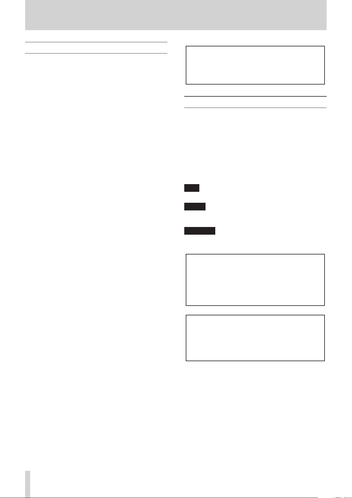
1 Built-in stereo microphone
Omnidirectional stereo electret condenser microphone.
2 Front cover
This is the cover for the battery case and SD card slot.
3 Battery compartment
Install batteries (4 AA) in this compartment to power the
unit. (See “Using AA batteries” on page 12.)
4 SD card slot
Insert an SD card here.
Rear panel
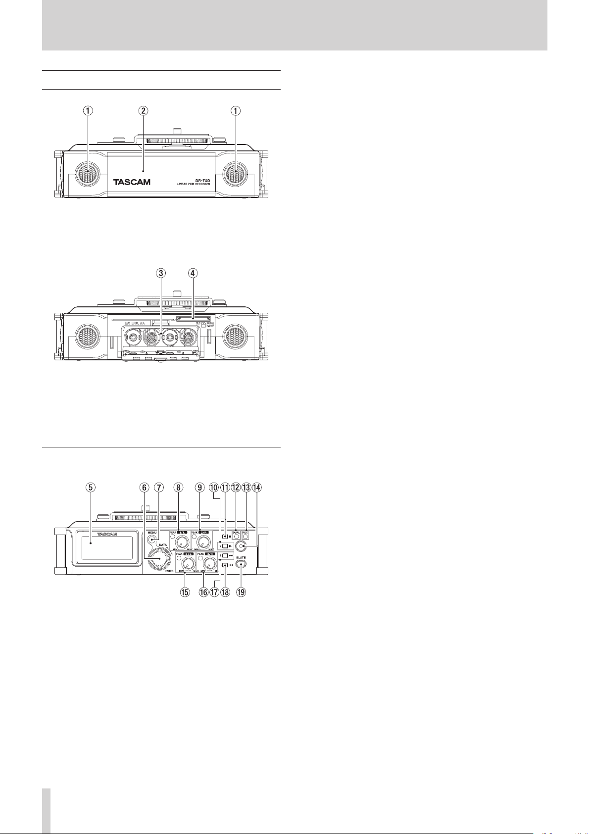
7 MENU button
When the Home Screen is open, press this button to open
the
MENU
screen.
When a setting screen is open, press to move up one level in
the menu. When the
the Home Screen.
MENU
screen is open, press to return to
8 1/L knob and PEAK indicator
Use this knob to adjust the input level from the 1/L
connector on the left side of the unit.
The 1/L PEAK indicator lights when the 1/L input level is
about to cause distortion. This also lights if distortion occurs
in the analog circuitry during mic input. This will not light,
however, if distortion occurs in the analog circuitry during
line input. (See “Adjusting the input level” on page 19.)
9 2/R knob and PEAK indicator
Use this knob to adjust the input level from the 2/R
connector on the left side of the unit.
The 2/R PEAK indicator lights when the 2/R input level is
about to cause distortion. This also lights if distortion occurs
in the analog circuitry during mic input. This will not light,
however, if distortion occurs in the analog circuitry during
line input. (See “Adjusting the input level” on page 19.)
0 1/8 button
Press this button during playback to cause the playback to
pause at the current position. Press this button when paused
to return to the beginning of the playback file.
Press this button during recording to stop recording.
When the BASIC screen or INPUT screen is open, use this to
select the channel to which the setting items shown apply.
When a setting screen is open, press this button to return
to the Home Screen. Use this button to answer “NO” to a
confirmation message.
q 2/7 button
When the Home Screen is open and playback is stopped,
press this button to start playback.
When a file or folder is selected in the
press this button to return to the Home Screen and play that
file or the first file in the folder from the beginning.
When the BASIC screen or INPUT screen is open, use this to
select the channel to which the setting items shown apply.
BROWSE
screen,
5 Display
Shows a variety of information.
6 DATA dial (ENTER)
Turn to select items and change values on setting screens.
Use also to change the playback position in a file.
Push this dial to confirm selections on setting screens and to
answer “YES” to confirmation pop-up messages.
Turn the DATA dial while the Home Screen is open to move
between the positions of slate tones that have been inserted
in the file. If no slate tone has been inserted in the file, doing
this will move to the next file.
Press and hold this dial when stopped to switch the signal
monitored.
TASCAM DR-70D
6
w DUAL indicator
This lights orange when in dual recording mode.
e REC indicator
This lights red when recording.
r Record (0) button
Press when stopped to start recording.
Press when recording to stop recording.
t 3/L knob and PEAK indicator
Use this knob to adjust the input level from the 3/L
connector on the left side of the unit.
The 3/L PEAK indicator lights when the input level is about
to cause distortion. This also lights if distortion occurs in
the analog circuitry during mic input. This will not light,
however, if distortion occurs in the analog circuitry during
line input. (See “Adjusting the input level” on page 19.)
y 4/R knob and PEAK indicator
Use this knob to adjust the input level from the 4/R
connector on the right side of the unit.
The 4/R PEAK indicator lights when the input level is about
to cause distortion. This also lights if distortion occurs in
the analog circuitry during mic input. This will not light,
Page 7
2 – Names and Functions of Parts
however, if distortion occurs in the analog circuitry during
line input. (See “Adjusting the input level” on page 19.)
u 3// button
Press this button during playback or when playback is
stopped to skip to the beginning of the next track.
Press and hold this button to search forward.
When the BASIC screen or INPUT screen is open, use this to
select the channel to which the setting items shown apply.
On the setting screens, use this button to move the cursor
right.
On the
BROWSE
a level. If a file is selected, the file is loaded and the Home
Screen reopens.
screen, press this button to move down
i 4/. button
During playback or when stopped in the middle of a file,
press to return to the beginning of the file.
If you press this button when a track is stopped at its
beginning, the unit will skip to the beginning of the previous
track.
Press and hold this button to search backwards.
When the BASIC screen or INPUT screen is open, use this to
select the channel to which the setting items shown apply.
On the setting screens, use this button to move the cursor
left.
On the
BROWSE
level.
screen, press this button to move up a
XLR (1: GND, 2: HOT, 3: COLD)
TRS (Tip: HOT, Ring: COLD, Sleeve: GND)
d 3/L connector (XLR/TRS)
This is a balanced analog XLR/TRS combo jack for microphone and line level inputs.
XLR (1: GND, 2: HOT, 3: COLD)
TRS (Tip: HOT, Ring: COLD, Sleeve: GND)
CAUTION
•
Confirm that phantom power is OFF before connecting a
line level device to the 1/L, 2/R, 3/L or 4/R connector. If you
connect a line level device while phantom power is being
supplied, that device and this unit could be damaged.
•
Before connecting a condenser mic to or disconnecting
one from the 1/L, 2/R, 3/L or 4/R connector, confirm that
the phantom power for that jack is OFF. If you connect or
disconnect a mic while phantom power is being supplied,
that mic and this unit could be damaged.
•
Do not connect an unbalanced dynamic mic to an XLR
connector when phantom power is being supplied. Doing so
could damage that mic and this unit.
Right side panel
o SLATE button
Press and hold this button during recording to record a slate
tone. (See “Recording slate tones” on page 26.)
Left side panel
NOTE
When connecting and using plugs from external devices,
do not apply excessive force to the plugs. In particular,
be careful not to apply too much force when using a
standard to mini plug adapter. Doing so could damage the
equipment.
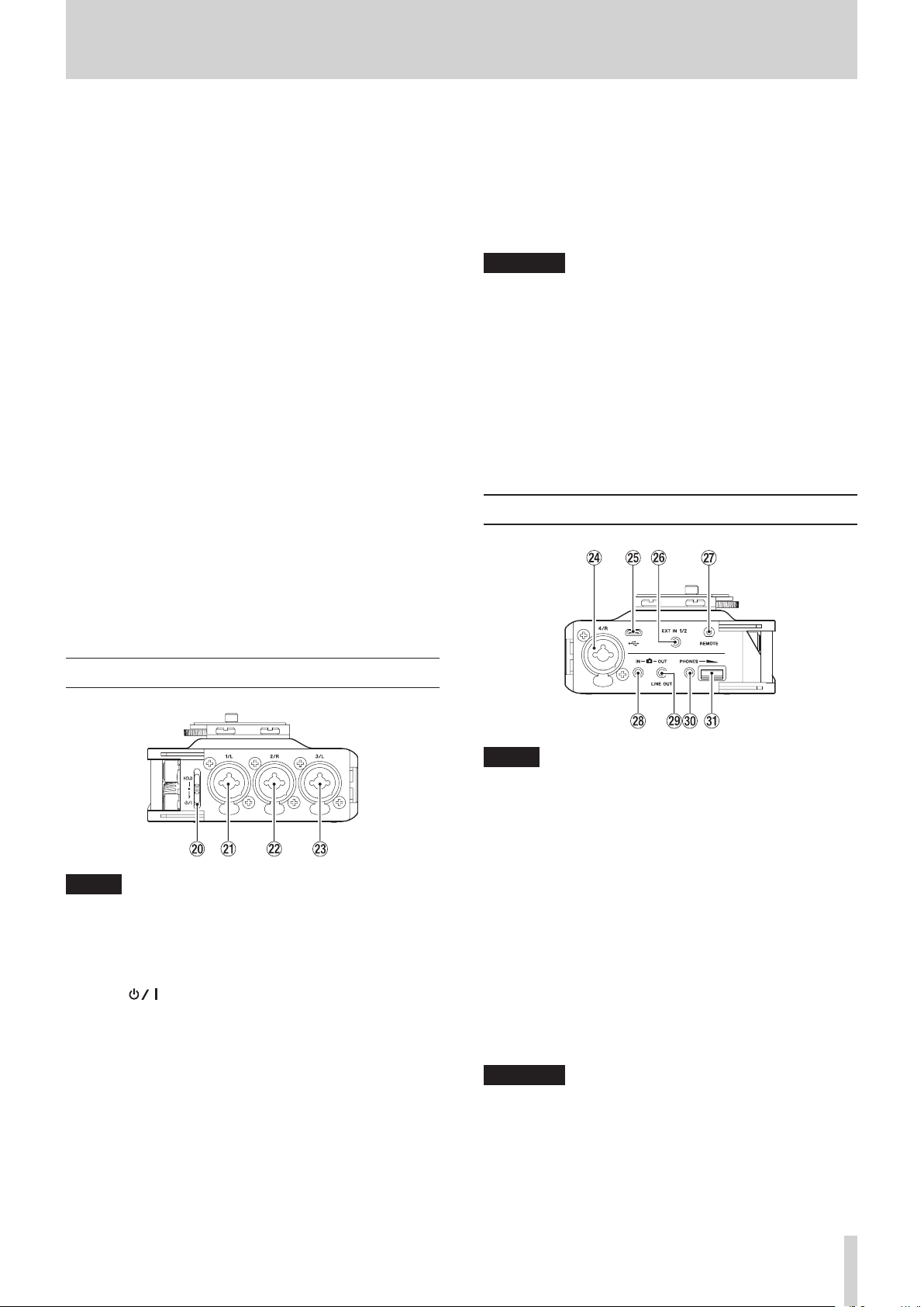
p HOLD/ switch
Slide this switch (toward the arrow) and hold it down to turn
the unit on/off.
Set it in the up position to activate the hold function. All
buttons are inoperative when hold is ON.
a 1/L connector (XLR/TRS)
This is a balanced analog XLR/TRS combo jack for microphone and line level inputs.
XLR (1: GND, 2: HOT, 3: COLD)
TRS (Tip: HOT, Ring: COLD, Sleeve: GND)
s 2/R connector (XLR/TRS)
This is a balanced analog XLR/TRS combo jack for microphone and line level inputs.
NOTE
When connecting and using plugs from external devices,
do not apply excessive force to the plugs. In particular,
be careful not to apply too much force when using a
standard to mini plug adapter. Doing so could damage the
equipment.
f 4/R connector (XLR/TRS)
This is a balanced analog XLR/TRS combo jack for microphone and line level inputs.
XLR (1: GND, 2: HOT, 3: COLD)
TRS (Tip: HOT, Ring: COLD, Sleeve: GND)
g Micro USB port
Use the included USB cable to connect with a computer USB
port. (See “7 – Connecting with a Computer” on page 32.)
Power can be supplied through the USB cable provided
with the unit or an AC adapter (TASCAM PS-P515U sold
separately).
CAUTION
The unit should be connected directly to the computer, not
through a USB hub.
h EXT IN 1/2 connector (3.5mm stereo mini jack)
This supports stereo mini jack input from a mic or external
device.
This jack can provide plug-in power.
TRS (Tip: HOT, Ring: COLD, Sleeve: GND)
TASCAM DR-70D
7
Page 8
2 – Names and Functions of Parts
j REMOTE connector (2.5mm TRS jack)
Connect a TASCAM RC-3F footswitch or TASCAM RC-10 wired
remote control (both sold separately) here to enable remote
starting and stopping of playback and other functions. A
remote control can be used to start, stop and otherwise
operate the unit. (See “9 – Using the REMOTE jack” on page
36.)
k IN connector (3.5mm stereo mini jack)
Connect to the audio output of a camera.
Refer to the camera’s operation manual to identify this
connector on the camera. (See “Camera connection and
attachment” on page 16.)
l OUT/LINE OUT jack (3.5mm stereo mini jack)
Use a stereo mini jack cable to connect this to the external
input jack of a camera or line input jack of other equipment.
Use the
SETTING
jack.
Refer to the camera’s operation manual to identify this
connector on the camera. (See “Camera connection and
attachment” on page 16.)
; PHONES jack (3.5mm stereo mini jack)
Connect stereo headphones to this stereo mini jack.
Use the PHONES control to adjust the volume.
OUTPUT LEVEL
screen to adjust the volume output from this
item on the
MONITOR
v Accessory shoe
You can use the accessory shoe by removing the included
DSLR attachment bracket
Bottom Panel
z PHONES volume control
Use to adjust the volume output from the PHONES jack.
CAUTION
Before connecting headphones, lower the PHONES volume
to the minimum level. Failure to do so could result in a
sudden loud noise that could harm hearing, for example.
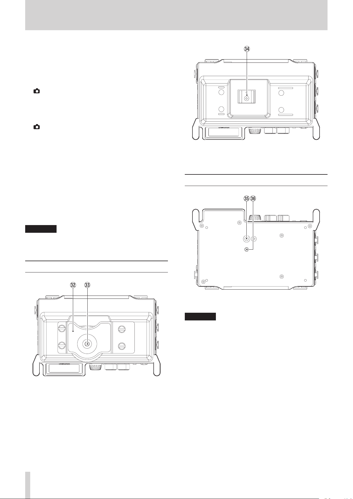
Top panel
x DSLR camera attachment bracket
Use a DSLR mounting screw with this bracket, which is preinstalled on the unit.
If you do not want to use this bracket, use a coin or other
tool to remove the four attachment screws.
b Tripod mounting thread (1/4-inch)
Use to attach this unit to a tripod.
CAUTION
•
Tighten the unit securely to the tripod or microphone stand
to prevent it from falling off.
•
When using this unit attached to a tripod or microphone
stand, place the tripod or stand on a level surface.
•
Some tripods have different screw specifications that make
direct connection impossible. Use a commercially-available
adapter with such tripods.
n Video camera pin hole
When using a tripod with a pin for video cameras, align this
hole with the pin when attaching the unit to the tripod.
c DSLR mounting screw (1/4-inch)
Use to attach this unit to the bottom of a camera or a rack
that supports camera mounting screws, for example.
TASCAM DR-70D
8
Page 9
2 – Names and Functions of Parts
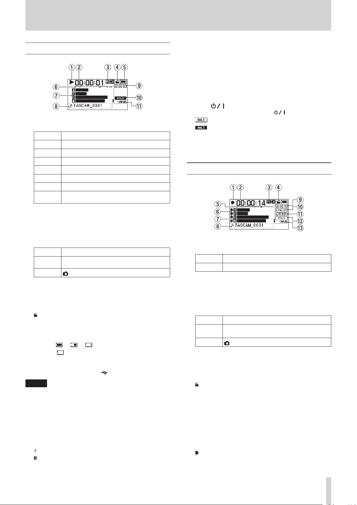
Home Screen
1 Recorder operation status
This icon shows the recorder operation status.
Indicator Meaning
8
9
7
,
m
/
.
2 Elapsed time
This shows the elapsed time (hours: minutes: seconds) of the
current file.
Stopped
Paused
Playing back
Searching forward
Searching backward
Skipping to the beginning of the next track
Skipping to the beginning of the current or
previous track
8 Project name
This shows the name of the project playing back.
A project is a group of files used for recording/playback.
9 Remaining time
This shows the elapsed time (hours: minutes: seconds) of the
current file.
When stopped, this shows the remaining recording time of
the SD card (hours: minutes: seconds).
0 HOLD/ switch status
This shows the status of the HOLD/ switch.
: HOLD switch off
: HOLD switch on
q Peak value in decibels (dB)
The maximum level that occurs in a fixed period of time is
displayed in decibels.
Recording Screen
3 Monitoring mode
This shows what audio is now being monitored.
Indicator Meaning
MIX
CAM
CH1-4 mix sound or dual recording mode main
file
IN jack sound input
4 Auto tone function status
This icon shows whether the auto tone function is on or off.
(See “Using the auto tone function” on page 26.)
No icon: Auto tone off
: Auto tone on
5 Power supply status
A battery icon appears when power is supplied by batteries.
The battery icon shows the amount of power remaining with
10 levels ( e e ).
When the icon has no bars, the batteries are almost dead
and the unit will soon turn off (enter standby).
When using a TASCAM PS-P515U AC adapter (sold
separately) or USB bus power, appears.
NOTE
Sometimes a “Battery Low” warning appears when recording
or conducting other demanding operations even before the
battery power has been depleted.
6 Level meters
These show the levels of the input and playback signals.
7 Recording status
These show the recording on/off status of each channel. (See
“Setting the channels to record” on page 18.)
: Recording off
: Recording on
1 Recorder operation status
This icon shows the recorder operation status.
Indicator Meaning
0
Recording
2 Elapsed recording time
The elapsed recording time of the file appears as hours:
minutes: seconds.
3 Monitoring mode
This shows what audio is now being monitored.
Indicator Meaning
MIX
CAM
CH1-4 mix sound or dual recording mode main
file
IN jack sound input
4 Auto tone function status
This icon shows whether the auto tone function is on or off.
(See “Using the auto tone function” on page 26.)
No icon: Auto tone off
: Auto tone on
5 Level meters
These show the input signal levels.
A b mark is shown at the −16dB position on the scale as a
guide for input level adjustment.
6 Phantom power status
This shows the phantom power on/off setting. (See “Using
phantom power” on page 21.)
No icon: Phantom power off
: Phantom power on
TASCAM DR-70D
9
Page 10
2 – Names and Functions of Parts
7 Recording status
These show the recording on/off status of each channel. (See
“Setting the channels to record” on page 18.)
: Recording off
: Recording on
8 Project name
This shows the name of the project for the recorded files.
9 Remaining recording time
The remaining recording time on the SD card is shown in
hours: minutes: seconds according to the recording mode,
sampling frequency and recording format settings.
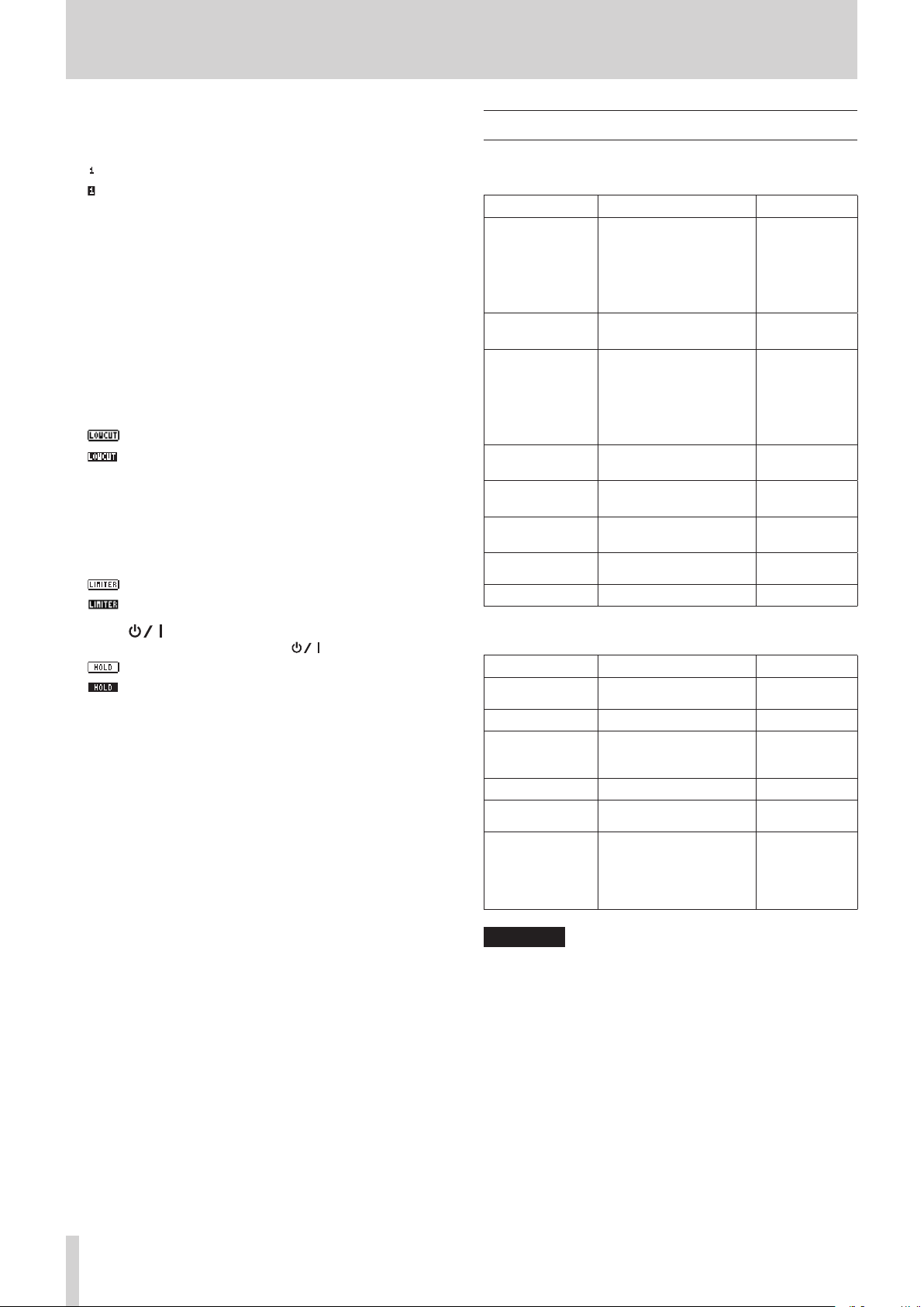
0 Low cut filter on/off status
This shows whether the low cut filter is on or off. (See “Using
the low-cut filter” on page 22.)
This icon is shown as light letters on a dark background if
the low-cut filter is set to 40Hz, 80Hz, 120Hz, 180Hz or 220Hz
for channel 1, 2, 3 or 4.
: Low cut filter off
: Low cut filter on
q Limiter function status
This shows the limiter function setting. (See “Using the
limiter” on page 22.)
This icon is shown as light letters on a dark background if the
limiter function setting is set to MONO or LINK for channel 1,
2, 3 or 4.
: limiter off
: Limiter on
w HOLD/ switch status
This shows the status of the HOLD/ switch.
: HOLD switch off
: HOLD switch on
e Peak value in decibels (dB)
Peak input level values are shown in decibels.
Menu item list
Press the MENU button to open the
This list provides an overview of the various menu items.
Menu item Function Page
BASIC Make recording settings
MONITOR
INPUT Make input settings
RECORD
SLATE Make slate tone settings
MIC Make mic settings
BROWSE
OTHERS Show submenu items
The
OTHERS
the
MENU
screen. The submenu items are as follows.
Submenu item Function Page
SYSTEM
BATTERY Set the type of batteries see page 34
INFORMATION
FILE NAME Make file name settings see page 35
DATE/TIME
REMOTE
Make monitoring output
settings
Make recording format
settings
Work with SD card files
and folders
submenu appears when
Make system settings for
the unit
View information about
files, the SD card and the
system
Make date and time
settings
Make settings for the
TASCAM RC-3F footswitch
and TASCAM RC-10 wired
remote control (both sold
separately)
MENU
OTHERS
screen.
see page 18
see page 18
see page 19
see page 20
see page 20
see page 16
see page 15
see page 20
see page 22
see page 22
see page 23
see page 23
see page 23
see page 25
see page 26
see page 26
see page 21
see page 27
see page 30
is selected in
see page 34
see page 33
see page 14
see page 36
see page 36
TASCAM DR-70D
10
CAUTION
The
MENU
screen will not appear when recording.
Page 11
2 – Names and Functions of Parts
Using menus
We explain how to change recording settings in this example.
1. Press the MENU button to open the
2. Turn the DATA dial to select (highlighted as light text on a
dark background) a menu item, and press the DATA dial or
3// button to open the setting screen.
RECORD
3. Turn the DATA dial to select (highlight) a menu item to be
set.
selected
MENU
screen.
Basic operation
Use the following buttons to operate the various screens.
8
MENU button
Opens the
8
When a setting screen is open, press the 1/8 button to return
to the Home Screen.
Use this to answer “NO” to confirmation pop-up messages.
8
Turn the DATA dial to select items and change values on setting
screens. You can also turn the DATA dial to change the file
playback position.
Push the DATA dial to confirm selections on setting screens and
to answer “YES” to confirmation pop-up messages.
8
Use this to move the cursor (highlighted area) to the right on the
screen, and to move down a level on the
8
Use this to move the cursor (highlighted area) to the left on the
screen, and to move up a level on the
MENU
screen.
1/8 button
DATA dial
3// button
4/. button
BROWSE
BROWSE
screen.
screen.
FILE TYPE
4. Press the DATA dial or 3// button to move the cursor to
highlight the value of the setting.
5. Turn the DATA dial to change the setting.
6. Press the DATA dial or 4/. button to set a different item
in the same menu.
This enables you to select a new item. Turn the DATA dial
again to select an item to be set.
7. Repeat steps 3 to 6 as necessary to set each item.
8. Press the MENU button to return to the
OTHERS
Press the 1/8 button to return to the Home Screen.
screen).
selected
MENU
screen (or
NOTE
When the
MENU button again to return to the Home Screen.
BASIC
or
INPUT
screen is open, press the
TASCAM DR-70D
11
Page 12

3 – Preparation
Powering the unit
Power sources
This unit can be powered by four AA batteries, a TASCAM
PS-P515U AC adapter (sold separately) or the included USB
cable (USB bus power).
This unit can use alkaline dry cell or Ni-MH AA batteries.
Using AA batteries
Open the front cover and battery compartment cover. Install 4
AA batteries in the compartment with the ¥ and ^ marks as
shown. Then, close the battery compartment cover and front
cover.
When using AA batteries, set the type of battery in order to
accurately show the amount of power remaining and allow the
unit to accurately determine whether power is available for
proper operation. (See “Setting the battery type” on page 34.)
CAUTION
•
This unit cannot use manganese dry cell AA batteries.
•
This unit cannot recharge Ni-MH AA batteries. Use a
commercially available recharger.
NOTE
A great amount of power is required to provide phantom
power to a condenser microphone. If you use a condenser
microphone while running the unit on AA batteries (NiMH
rechargeable or alkaline dry cell), the operation time will be
shortened.
If you need to operate the unit for a long time, use a TASCAM
PS-P515U AC adapter or TASCAM BP-6AA external battery
box (both sold separately) to power the unit.
Using an AC adapter (sold separately)
Connect the USB cable to the TASCAM PS-P515U AC adapter and
the unit's USB port as shown in the illustration.
AC outlet
TASCAM PS-P515U
(sold separately)
Connect the
included USB cable
microB USB plug
NOTE
When both batteries are installed and the AC adapter is
connected, power will be supplied from the AC adapter.
CAUTION
•
Never use any adapter other than the designated TASCAM
PS-P515U AC adapter. Use of a different adapter could cause
malfunction, fire or electric shock.
•
Noise may occur when recording with a microphone if the
unit is too close to the AC adapter. In such a case, keep sufficient distance between the AC adapter and the unit.
Using an external battery pack (sold separately)
Connect a TASCAM BP-6AA external battery pack (designed for
use with this unit and sold separately) to the recorder with the
included USB cable as shown in the illustration. For details, see
the BP-6AA Owner’s Manual.
TASCAM BP-6AA (sold separately)
Connect the included
USB cable
microB USB plug
TASCAM DR-70D
12
CAUTION
This unit cannot detect the remaining battery charge of a
BP-6AA. If you use a BP-6AA to operate this unit without
batteries in the unit itself, it might stop operating suddenly
if the battery pack runs out of power.
In order to avoid problems, put batteries with sufficient
charge into this unit before connecting and using a BP-6AA.
Page 13
3 – Preparation
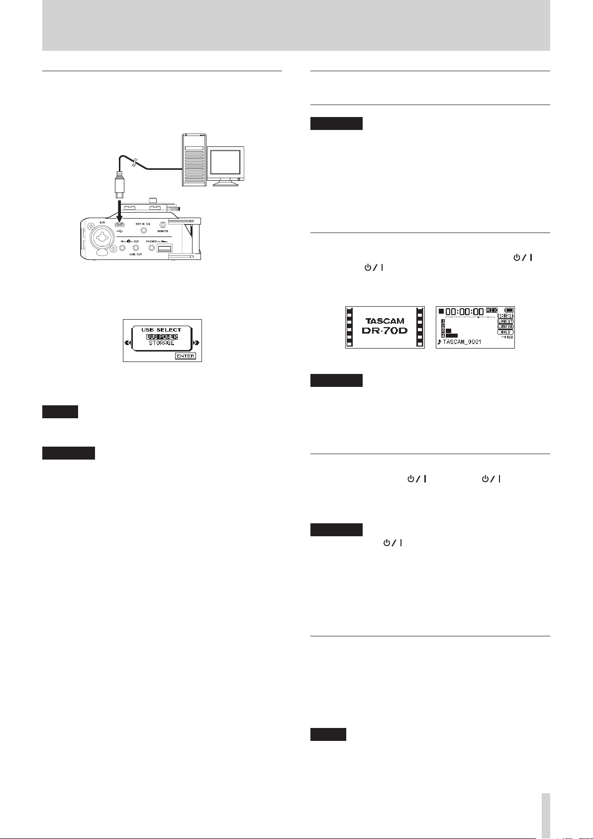
Using USB bus power
Connect the unit to a computer using the included USB cable as
shown in the illustration.
Computer
Connect the included USB
cable
microB USB plug
The
USB SELECT
by USB and when the unit is turned on if the USB cable is already
connected. On this screen, choose between USB bus power
supply or USB connection with the computer.
Turn the DATA dial to select
dial to start power supply through the USB port and return to
the Home Screen.
NOTE
Power is supplied from the USB port even if the connected
unit contains batteries (USB bus power prioritized).
screen appears when the unit is connected
BUS POWER
and press the DATA
Turning the unit on and off (putting it in standby)
CAUTION
•
The unit enters standby mode if turned off when the unit is
operating on power from a TASCAM PS-P515U AC adapter
(sold separately) or a computer USB bus.
•
Turn down the volume of any monitoring system connected
to the unit before turning the unit on or off (standby).
•
Do not wear connected headphones when turning the unit
on or off. Noise could damage the speakers or harm your
hearing.
Turning the unit on
To start the unit when off (in standby), slide the HOLD/
switch toward until
appears on the display.
The Home Screen appears after the unit starts up.
Start-up Screen Home Screen
CAUTION
When the unit is started up for the first time (or when
the built-in clock is reset after being left unused without
batteries), the
Start-up Screen so you can adjust the date and time. (See
“Setting the date and time” on page 14.)
TASCAM DR-70D
DATE/TIME
screen appears before the
(Start-up Screen)
CAUTION
•
Depending on the USB bus power specifications of the
computer, this unit might not function when connected
to a computer by USB cable. In this case, use a TASCAM
PS-P515U AC adapter (sold separately) or batteries.
•
This unit does not support computer power conservation
and sleep functions. When powering the unit using the USB
bus power of a computer, always turn such functions off.
Turning the unit off (putting it in standby)
When on, slide the HOLD/ switch toward until
LINEAR PCM RECORDER
The unit turns off (enters standby) after it completes its
shutdown process.
appears on the display.
CAUTION
Always use the button to turn the unit off (put it in
standby).
Do not remove the batteries, disconnect the power
cable when using a TASCAM PS-P515U AC adapter (sold
separately) or disconnect the USB cable if using USB bus
power while the unit is operating. If you do so, recording
data and settings, for example, will all be lost. Lost data and
settings cannot be restored.
Resume function
This unit has a resume function. When turned on, the unit
locates to the position (time) where it was when turned off
previously.
After turning the unit on, press the 2/7 button to
resume playback from the file position (time) from when the
unit was shut down (put into standby).
NOTE
The required data for this function is stored in the SD card.
The resume function will not work if the card is changed or
formatted.
TASCAM DR-70D
13
Page 14

3 – Preparation
Setting the date and time
Using its internal clock, this unit adds the date and time to files
when they are recorded.
1. Press the MENU button to open the
2. Turn the DATA dial to select
dial.
The
OTHERS
3. Turn the DATA dial to select
DATA dial.
The
DATE/TIME
4. Use the DATA dial or the 4/. and 3// buttons to
move the cursor (highlighted area), and turn the DATA dial
to change the value.
5. Press the MENU button to confirm the setting and return to
the
OTHERS
screen opens.
screen opens.
screen.
MENU
OTHERS
DATE/TIME
, and press the DATA
screen.
, and press the
Inserting and removing SD cards
Inserting a card
1. Open the front cover on the front of the unit.
2. Insert an SD card as shown in the illustration until it clicks
into place.
Removing a card
1. Open the front cover on the front of the unit.
2. Press the SD card in gently and then release it to allow it to
come out.
NOTE
You can set the unit to automatically add the date set here
to file names. (See “Setting the file name format” on page
35.)
CAUTION
The date and time setting can only be maintained for a
few minutes if the battery power becomes low and the unit
is not powered by a TASCAM PS-P515U AC adapter (sold
separately) or USB bus power.
When using batteries, replace them before they completely
lose power.
CAUTION
•
Do not remove the SD card from the unit during recording,
playback or at other times when it is being accessed.
•
Do not remove the SD card from the unit when it is
connected to a computer by USB.
•
SD cards that meet SD, SDHC or SDXC standards can be used
with this unit.
•
A list of SD cards that have been confirmed to work with
this unit can be found on the TEAC Global Site (http://
teac-global.com/).
TASCAM DR-70D
14
Page 15

3 – Preparation
SD card write protection switches
SD cards have protect switches that prevent writing new data to
them.
If you slide the protect switch to the LOCK position, file
recording and editing is not possible. Move the switch to the
unlocked position in order to record, erase and otherwise edit
data on the card.
Writing possible Writing not possible
Preparing an SD card for use
In order to use an SD card in this unit, you must format it first.
1. Confirm that an SD card is loaded and turn the unit on.
2. A message like one of the following appears when a new
card or a card formatted by another device is installed in the
unit.
Connecting monitoring equipment
Connect an external stereo mic to the EXT IN 1/2 jack on the
right side of the unit.
To listen with headphones, connect them to the PHONES jack.
To listen with an external monitoring system (powered monitor
speakers or an amplifier and speakers), connect it to the OUT/
LINE OUT jack.
External mic
Powered monitor
speakers or
amplifier and
speakers
Headphones
SD/SDHC card
SDXC card
3. Press the DATA dial to start formatting.
CAUTION
Formatting a card erases all the data on it.
4. When formatting ends, the Home Screen opens. You can
also reformat a card in this unit at any time.
CAUTION
When formatting a card, the unit should be operating on
AC power supplied by a TASCAM PS-P515U adapter (sold
separately), USB bus power from a computer or batteries
with sufficient remaining power.
Monitoring
You can monitor the input signals when the unit is stopped
using headphones, for example. Moreover, by connecting this
unit’s IN jack with the camera line output, you can check the
sound being recorded by the camera.
Selecting the monitored signal
1. Press the MENU button to open the
2. Turn the DATA dial to select
dial.
The
MONITOR SETTING
3. Turn the DATA dial to select
the DATA dial.
4. Turn the DATA dial to select the sound to monitor, and press
the DATA dial.
Options
CAM: IN jack sound input
MIX (default): Mix of all inputs
5. When finished selecting the monitoring signal, press the
1/8 button to return to the Home Screen.
MONITOR
MONITOR SEL
MENU
, and press the DATA
screen opens.
screen.
, and press
NOTE
•
You can also press and hold the DATA dial when stopped to
switch the signal monitored.
•
When
CAM
is selected, you can monitor the input sound
through the PHONES jack, but the level meters will show
the input sound according to the current recording mode.
TASCAM DR-70D
15
Page 16

3 – Preparation
Setting the output gain
1. Press the MENU button to open the
2. Turn the DATA dial to select
dial.
The
MONITOR SETTING
3. Turn the DATA dial to select
the DATA dial.
4. Turn the DATA dial to select the OUT or the LINE OUT
jack, and press the DATA dial.
Options
LINE (default): Set the output gain for output to an
external monitoring system (powered monitor speakers or
amplifier and speakers)
CAM: Set the output gain for output to a camera
5. When finished setting the output gain, press the 1/8
button to return to the Home Screen.
MENU
screen.
MONITOR
screen opens.
OUTPUT GAIN
, and press the DATA
, and press
Adjusting the playback volume
Use the PHONES volume control to adjust the volume output
from the PHONES jack. Use the
MONITOR SETTING
from the OUT/LINE OUT jack.
OUTPUT LEVEL
screen to adjust the volume output
item on the
Camera connection and attachment
In order to output the sound from this unit to a DSLR camera
and monitor sound from the camera with this unit, you must
connect them with commercially-available 3.5mm stereo mini
plug cables.
1. Press the MENU button to open the
2. Turn the DATA dial to select
dial.
The
MONITOR SETTING
3. Turn the DATA dial to select
the DATA dial.
4. Turn the DATA dial to select
Options: LINE (default), CAM
5. If you want to record audio from this unit with a camera,
connect the OUT jack on the right side of this unit with
the external mic input on the camera.
If you want to input audio from the camera and monitor it
with this unit, connect the IN jack on the right side of this
unit with the audio output jack on the camera.
MONITOR
OUTPUT GAIN
CAM
MENU
screen.
, and press the DATA
screen opens.
, and press
, and press the DATA dial.
DSLR camera
External mic input jack
Audio output jack
NOTE
Refer to the camera’s operation manual to identify this
connector on the camera.
6. Use the
SETTING
camera.
OUTPUT LEVEL
screen to adjust the volume output to the
item on the
MONITOR
NOTE
If the volume is still too low even if you set the
LEVEL
its maximum value, set the
MONITOR SETTING
the volume.
7. To mount the camera on this unit, use the camera
attachment screw on the top of the unit.
item on the
MONITOR SETTING
OUTPUT GAIN
screen to
LINE
OUTPUT
screen to
item on the
and then adjust
TASCAM DR-70D
16
Page 17

3 – Preparation
Setting the inputs
Recording with the built-in stereo mic
Point the built-in stereo mic at the sound source and place the
unit in a stable location where there is little vibration.
Connecting microphones
Connect microphones to this unit’s 1/L, 2/R, 3/L and/or 4/R
connectors.
Point the mics at the sound source and place the unit in a stable
location where there is little vibration.
Mic
Mic
Mic
Recording an external device (LINE IN)
Use stereo plug cables to connect to the output of an external
audio device.
Audio equipment or other external device
CAUTION
•
Reduce the output level of the external audio device if the
input sound is distorted even after adjusting the input gain
level of the unit.
•
Controlling the gain level might not be possible if an
external audio device with a fixed output line level is
connected and overloads might occur because of excessively loud input signals. In such cases, use the headphone
jack or other level-controllable output for connection to the
unit.
Mic
Using the top panel accessory shoe
To use the accessory shoe on the top panel, remove the DSLR
attachment bracket.
Stereo microphone
You can attach the included camera attachment bracket screw
hole covers to the screw holes.
TASCAM DR-70D
17
Page 18

4 – Recording
This unit can record sound from external microphones and
external audio devices, including CD players.
The unit can be set to record audio files in WAV or BWF
(44.1/48/96kHz, 16/24-bit) format.
Slate tones added when recording to Broadcast Wave Format
(BWF) files can be used as marks with software that supports this
format. This unit can record using dual recording, which allows
the same input signals to be recorded at two different levels,
and 4-channel recording, for example.
Recording formats
You can select the format of files created by this unit.
8
MONO mode
The channels selected for recording will be recorded as mono
files.
A file will be made for each channel selected for recording.
8
STEREO mode
Stereo files will be recorded.
Examples:
If only channel 1 is selected for recording, a stereo file with
channel 2 silent will be created.
If only channels 1 and 3 are selected for recording, stereo
files with channels 2 and 4 silent will be created.
8
MIX mode
The input signals set on the BASIC screen will be recorded as a
stereo file.
Even if all four channels are selected for recording, a stereo file
will be created.
Setting where to save files
Set the folder where recorded files are saved.
The recorded file will be saved in the currently selected folder.
For details, see the SELECT pop-up menu item in “Folder operations” on page 30.
If no setting is made, new files are created in the MUSIC folder.
Setting the channels to record
By default, the channel recording settings are ON. To turn
recording for a channel off, set the
screen to
1. Press the MENU button to open the
2. Turn the DATA dial to select
3. Press the 1/8, 2/7, 3// or 4/. button to select the
4. Turn the DATA dial to select
5. Turn the DATA dial to turn the recording setting ON/OFF.
6. Repeat steps 3 to 5 as necessary to turn recording on/off for
7. When finished, press the MENU button to return to the
OFF
.
dial.
The BASIC screen opens.
recording channel that you want to set.
channel, and press the DATA dial.
CH1 BASIC screen
Options: ON (default), OFF
each channel.
Home Screen.
RECORD
MENU
BASIC
RECORD
, and press the DATA
item on the BASIC
screen.
for the selected
Adjusting the input balance
You can set the left-right position of each recording channel
with the PAN item on the BASIC screen.
1. Press the MENU button to open the
2. Turn the DATA dial to select
dial.
The BASIC screen opens.
3. Press the 1/8, 2/7, 3// or 4/. button to select the
channel for balance adjustment.
4. Turn the DATA dial to select
and press the DATA dial.
BASIC
PAN
MENU
screen.
, and press the DATA
for the selected channel,
TASCAM DR-70D
18
CH1 BASIC screen
5. Turn the DATA dial to set the input balance.
Options: LEFT 12 − CENTER − RIGHT 12
6. Repeat steps 3 to 5 as necessary to set the input balance for
each channel.
7. When finished adjusting, press the MENU button to return
to the Home Screen.
Page 19

4 – Recording
Adjusting the input level
Before starting recording, the input level should be adjusted
to prevent the recorded sounds or input signals from being
distorted due to excessively loud input or from being quieter
than the noise level due to excessively low input levels.
In addition to manual adjustment, the unit has a limiter function
that you can use as desired. (See “Using the limiter” on page
22.)
TIP
In addition to adjusting the INPUT level, try changing the
distance and angle between the microphone and the sound
source. The angle and distance of the microphone can also
change the character of the recorded sound.
1. Press the MENU button to open the
2. Turn the DATA dial to select
dial.
The BASIC screen opens.
3. Press the 1/8, 2/7, 3// or 4/. button to select the
channel for input level adjustment.
4. Turn the DATA dial to select
and press the DATA dial.
CH1 BASIC screen
MENU
screen.
BASIC
GAIN
, and press the DATA
for the selected channel,
7. Use the 1/L, 2/R, 3/L and 4/R knobs on the back of the unit
to adjust the input levels.
If an input level is too high, the PEAK indicator to the left of
the knob will light red.
The level meters have a b mark as a guide at −16dB.
Set input level so that level changes occur near this mark
without causing PEAK indicators to light red.
CAUTION
These also light if distortion occurs in the analog circuitry
during mic input.
They will not light, however, if distortion occurs in the
analog circuitry during line input.
NOTE
To monitor the sound while adjusting the input levels or
recording, connect headphones to the PHONES jack.
Use the PHONES jack volume control to adjust the
monitoring level.
8. Repeat steps 3 to 6 as necessary to set the mic input gain for
each channel.
NOTE
To change the channel being set, turn the data dial or
press the 1/8, 2/7, 3// or 4/. button to move to a
different channel screen.
5. Turn the DATA dial to set the mic input gain.
Options: LOW (default), MID, HIGH, HI+PLUS
NOTE
The input gain is different for the
HI+PLUS
loudness of the input.
If you are not sure which setting to use, try
input level is too low even after adjustment, return to the
INPUT screen and set it to
If the level is still too low, set the GAIN to
HI+PLUS
6. When finished adjusting, press the MENU button to return
to the Home Screen.
settings. Make a selection according to the
and then adjust the level.
LOW, MID, HIGH
MID
.
LOW
HIGH
and
first. If the
or
TASCAM DR-70D
19
Page 20

4 – Recording
Setting the recording input source
Use the
INPUT 1/2
screen to set the recording input source.
1. Press the MENU button to open the
2. Turn the DATA dial to select
dial.
The BASIC screen opens.
3. Turn the DATA dial to select
3/4
for the selected channel, and press the DATA dial.
4. Turn the DATA dial to select the input source for the
recording channel.
Item Option Meaning
INPUT 1/2
INPUT 3/4
5. When finished adjusting, press the MENU button to return
to the Home Screen.
Using plug-in power
The plug-in power function can be turned on when an external
mic that requires it is connected to the EXT IN 1/2 jack.
1. Press the MENU button to open the
2. Turn the DATA dial to select
dial.
The BASIC screen opens.
3. Press the 1/8 or 2/7 button to show the
item.
4. Turn the DATA dial to select
DATA dial.
The cursor moves to the setting item.
5. Turn the DATA dial to set it to
DATA dial.
This turns plug-in power on. A different setting item can
now be selected.
6. When finished, press the MENU button to return to the
Home Screen.
and
INPUT 3/4
BASIC
INPUT 1/2
CH1 BASIC screen
EXT STEREO
(default)
EXT POWER
XLR/TRS Input from the 1/L and 2/R jacks
MIC (default) Input from the built-in mic
XLR/TRS Input from the 3/L and 4/R jacks
Input from the EXT 1/2 jack
Input from the EXT 1/2 jack
(plug-in power on)
BASIC
INPUT 1/2
EXT_POWER
items on the BASIC
MENU
screen.
, and press the DATA
or
INPUT
MENU
screen.
, and press the DATA
INPUT 1/2
, and press the
, and press the
CAUTION
•
When connecting a dynamic mic or external mic that has its
own battery, set
it to
EXT_POWER
•
Use headphones to monitor when you are recording with a
microphone. If you use speakers for monitoring, the sound
output from the speakers could be picked up by the mic,
resulting in its unwanted recording or feedback noise.
INPUT 1/2
could damage such microphones.
to
EXT_STEREO
. Setting
Setting the input gain
Set the
INPUT GAIN
the type of equipment connected.
1. Press the MENU button to open the
2. Turn the DATA dial to select
dial.
The INPUT screen opens.
3. Press the 1/8, 2/7, 3// or 4/. button to select the
channel for input gain setting.
4. Turn the DATA dial to select
channel, and press the DATA dial.
5. Turn the DATA dial to set the input gain.
Options
LINE:
Use this setting when connecting line output jacks of
external devices to the analog inputs of this recorder.
MIC (default):
Use this setting when connecting mics to the recorder.
MIC+PHANTOM:
Use this setting when connecting condenser mics that
require phantom power (24V or 48V) to the recorder.
If the INPUT1/2 or INPUT3/4 item on the BASIC screen
for the channel being set is set to XLR/TRS, when you
set it to MIC+PHANTOM, a pop-up message appears
confirming that you want to turn phantom power on.
(See “Using phantom power” on page 21.)
Use the
to
24V
voltage” on page 21.)
6. When finished, press the MENU button to return to the
Home Screen.
CAUTION
Depending on this setting, the input level setting range
changes. For this reason, the input level might change
greatly when this setting is changed, so turn the output level
all the way down before changing it.
item on the INPUT screen according to
MENU
screen.
INPUT
INPUT GAIN
CH1 INPUT screen
MIC SETTING
or
48V
. (See “Setting the phantom power
, and press the DATA
screen to set the voltage
for the selected
TASCAM DR-70D
20
Page 21

4 – Recording
Using phantom power
When stopped (and the INPUT1/2 or INPUT3/4 item is set
to XLR/TRS on the BASIC screen for the channel being set),
if you set the
MIC+PHANTOM
you want to turn phantom power on.
When the confirmation pop-up message opens, press the DATA
dial to turn phantom power (24V or 48V) on for the 1/L, 2/R, 3/L
and 4/R connectors and supply it to the connected mics.
Use the
48V
. (See “Setting the phantom power voltage” on page 21.)
NOTE
Battery power will be consumed faster when set to 48V than
when set to 24V.
CAUTION
•
Confirm that phantom power is OFF before connecting a
line level device to the 1/L, 2/R, 3/L or 4/R connector. If you
connect a line level device while phantom power is being
supplied, that device and this unit could be damaged.
•
Before connecting a condenser mic to or disconnecting
one from the 1/L, 2/R, 3/L or 4/R connector, confirm that
the phantom power for that jack is OFF. If you connect or
disconnect a mic while phantom power is being supplied,
that mic and this unit could be damaged.
•
Turn phantom power ON only when using a condenser
microphone that requires phantom power.
•
Supplying phantom power to some ribbon mics will break
them. If you are unsure, do not supply phantom power to a
ribbon mic.
•
When using USB bus power, the unit might not be able to
supply phantom power depending on the computer. In this
case, use a TASCAM PS-P515U AC adapter (sold separately).
•
Some condenser microphones will not operate when
phantom power is set to 24V.
•
Do not connect or disconnect the power cable connected
to the USB port when using phantom power. Doing so
could interrupt the power to the unit even if it has batteries,
resulting in the damage or loss of recording data.
INPUT GAIN
, a pop-up message appears confirming that
MIC SETTING
item on the INPUT screen to
screen to set the voltage to
24V
or
Setting the phantom power voltage
Use the
PHANTOM VOLT
screen to set the power voltage supplied when a microphone
that requires phantom power is connected.
1. Press the MENU button to open the
2. Turn the DATA dial to select
The
MIC SETTING
3. Turn the DATA dial to select
the DATA dial.
4. Turn the DATA dial to set the voltage of phantom power
when it is supplied.
Options: 24V, 48V (default)
NOTE
Battery power will be consumed faster when set to
than when set to
5. When finished, press the 1/8 button to return to the Home
Screen.
item on the
screen opens.
24V
.
MIC SETTING
MENU
screen.
MIC
, and press the DATA dial.
PHANTOM VOLT
, and press
48V
TASCAM DR-70D
21
Page 22

4 – Recording
Using the limiter
When the limiter is on, the input gain will adjust automatically
in response to the input level, setting the recording level so that
distortion does not occur even when loud sounds are input.
1. Press the MENU button to open the
2. Turn the DATA dial to select
dial.
The INPUT screen opens.
3. Press the 1/8, 2/7, 3// or 4/. button to select a
channel to use the limiter on.
4. Turn the DATA dial to select the
channel, and press the DATA dial.
CH1 INPUT screen
5. Turn the DATA dial to set the limiter.
Options Meaning
OFF (default) Limiter off
MONO Limiter on only for selected channel
LINK
Limiter on for both selected and linked
channels
INPUT
LIMITER
MENU
screen.
, and press the DATA
for the selected
Using the low-cut filter
The low-cut filter can reduce noise from, for example, air-conditioners and projectors as well as wind.
1. Press the MENU button to open the
2. Turn the DATA dial to select
dial.
The INPUT screen opens.
3. Press the 1/8, 2/7, 3// or 4/. buttons to select the
channel to use the low-cut filter on.
4. Turn the DATA dial to select
channel, and press the DATA dial.
CH1 INPUT screen
5. Turn the DATA dial to select the cut off frequency of the low
cut filter.
Options: OFF (default), 40Hz, 80Hz, 120Hz, 180HZ, 220Hz
6. Repeat steps 3 to 5 as necessary to set the low-cut filter for
each channel.
7. When finished, press the MENU button to return to the
Home Screen.
INPUT
LOW CUT
MENU
screen.
, and press the DATA
for the selected
6. Repeat steps 3 to 5 as necessary to set the limiter for each
channel.
7. When finished, press the MENU button to return to the
Home Screen.
CAUTION
Distortion might occur if the input sound is too loud even
when the limiter is on. In such a case, lower the input level
or increase the distance between the unit and the sound
source.
NOTE
•
The icon appears on the recording screen when the
limiter is on for any channel (when set to
•
When you switch the CH1 (CH2)/CH3 (CH4) limiter setting
between
will also be changed, so a confirmation pop-up message will
appear.
Pop-up message when changing between
•
When set to
has excessive input. When set to
both channels in the pair when either has excessive input.
MONO
MONO
and
LINK
, the setting of the other channel
, the limiter only affects the channel that
LINK
MONO
or
LINK
MONO
and
LINK
, the limiter affects
).
TASCAM DR-70D
22
Page 23

4 – Recording
Compensating for mic distances
This unit can compensate for delays that result from differences
in distance between the built-in and external mics, as well as
between external mics.
1. Press the MENU button to open the
2. Turn the DATA dial to select
dial.
The INPUT screen opens.
3. Press the 2/7, 3// or 4/. button to select the
channel to compensate for distance relative to CH1.
4. Turn the DATA dial to select
channel, and press the DATA dial.
5. Turn the DATA dial to set this value according to the
distance of the connected mic.
Range: 0ms (default) to ±150ms (in 1ms increments)
6. When finished, press the MENU button to return to the
Home Screen.
INPUT
DELAY
MENU
screen.
, and press the DATA
for the selected
Setting the phase of each channel
You can set the input phase.
1. Press the MENU button to open the
2. Turn the DATA dial to select
dial.
The INPUT screen opens.
3. Press the 1/8, 2/7, 3// or 4/. button to select the
channel for phase adjustment.
4. Turn the DATA dial to select PHASE for the selected channel,
and press the DATA dial.
5. Turn the DATA dial to set the phase of the selected channel.
Options: OFF (default, normal phase), ON (reversed phase)
6. Repeat steps 3 to 5 as necessary to set the phase for each
channel.
7. When finished adjusting, press the MENU button to return
to the Home Screen.
INPUT
MENU
screen.
, and press the DATA
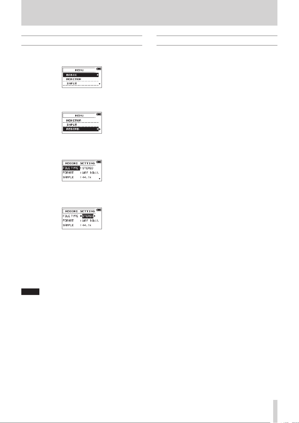
This shows the file type, format and sampling frequency used for recordings.
Set the audio file type that you want to record before you start
recording.
1. Press the MENU button to open the
2. Turn the DATA dial to select
dial.
The
RECORD SETTING
3. Turn the DATA dial to select
DATA dial.
4. Turn the DATA dial to select the recording file type.
Options Meaning
MONO Record in mono
STEREO (default) Record in stereo
2MIX Record mixed signal in stereo
5. Press the DATA dial to enable selection of other items.
6. Turn the DATA dial to select
dial.
Set the file format.
Turn the DATA dial to select one of the following options.
Options: BWF 16bit, BWF 24bit, WAV 16bit (default), WAV
24bit
RECORD
screen opens.
FILE TYPE
FORMAT
NOTE
BWF is a format created for broadcasting that has the same
sound quality as the standard WAV format. It also uses the
same “.wav” file extension as WAV files. In this document,
we distinguish these file types by using the “BWF” for WAV
files that support BWF features and “WAV” for all other WAV
files.
7. Press the DATA dial or 3// button to enable selection of
other items.
8. Turn the DATA dial to select
dial.
Set the sampling frequency.
Turn the DATA dial to select one of the following options.
Options: 44.1k (default), 48k, 96k
9. Press the DATA dial or 4/. button to move the cursor
back to the setting item.
10. When finished, press the 1/8 button to return to the Home
Screen.
SAMPLE
MENU
screen.
, and press the DATA
, and press the
, and press the DATA
, and press the DATA
TASCAM DR-70D
23
Page 24

4 – Recording
TASCAM0001S1.WAV
TASCAM0002S12.WAV
Recording (MONO/STEREO/2MIX)
Starting recording
1. Press the record (0) button to start ordinary recording.
When recording starts, the REC indicator lights continuously,
and the display shows the elapsed recording time and the
remaining recording time.
2. Press the record (0) or 1/8 button to stop recording.
NOTE
To avoid recording the noise of pressing the record (0)
button, recording starts 0.3 second after the button is
pressed.
File names when recording in MONO
When mono recording, a file will be made for each channel.
The file names will be as follows.
Creating a new file without interrupting recording (track incrementing)
You can manually create a new file without pausing recording
and set the unit to automatically do the same when the file size
reaches 2 GB.
Manual track incrementation during recording
You can manually split a recording by creating a new file.
1. Press the 3// button while recording to create a new file.
NOTE
When new files are created, incremental numbers are added
to the end of each file name.
CAUTION
•
A new file cannot be created if the total number of folders
and files would exceed 5000.
•
Files shorter than two seconds cannot be created. Moreover,
if the sampling frequency is 96 kHz, files shorter than four
seconds cannot be created.
•
If the name of a newly created file would be the same as
that of an existing file, the number will be incremented until
the new file has a unique name.
1: Set with the
WORD
item on the
FILE NAME
screen
2: Recording file project number
3: Source file
4: Assigned channel
File names when recording in STEREO/2MIX
When stereo recording, a file will be made for the 1/2 or 3/4
channel pair.
The file names will be as follows.
1: Set with the
2: Recording file project number
3: Source file
4: Assigned channels
WORD
item on the
FILE NAME
screen
Automatic track incrementation during recording
Without pausing recording, a new file can be created automatically during recording when the file size reaches 2 GB.
CAUTION
A new file cannot be created if the total number of folders
and files would exceed 5000.
TASCAM DR-70D
24
Page 25

4 – Recording
TASCAM0003S12.WAV
TASCAM0003SD12-05.WAV
Simultaneously recording two files at different input levels (DUAL REC)
This recorder can simultaneously record a second recording
at a different input level along with the regular recording. For
example, when recording with microphones, you can make an
ordinary recording with the input level set as high as possible
and simultaneously record at a slightly lower input level for
safety.
Two recorded files (one with higher input level and one with
lower input level) are saved individually.
NOTE
Make the input level setting for the ordinary recording in
the usual manner. (See “Adjusting the input level” on page
19.), (See “Setting the input gain” on page 20.)
Enabling dual recording
1. Press the MENU button to open the
2. Turn the DATA dial to select
dial.
The
RECORD SETTING
3. Turn the DATA dial to select
DATA dial.
4. Turn the DATA dial to set the input gain level of the other
recording.
Options: OFF (default), −1dB to −12dB (in −1dB increments)
screen opens.
NOTE
This function cannot be enabled if more than two channels
are selected for recording or if the two selected channels
prevent the recording of a stereo pair (for example, CH1 and
CH3).
5. Press the DATA dial or 4/. button to enable selection of
other items.
6. When finished, press the 1/8 button to return to the Home
Screen.
MENU
RECORD
DUAL REC
, and press the DATA
screen.
, and press the
Starting dual recording
Press the record (0) button to start dual recording.
During dual recording, the recording screen appears as follows.
In the input source display area of the recording screen, the
input levels of the current input source and the dual recording
are shown.
Dual recording file names
Dual recording will create two files simultaneously.
The name of the second file created by dual recording has “-XX”
added to the file name of the ordinary recording.
“-XX” shows the amount that the input level has been lowered.
1: Set with the
2: Recording file project number
3: S is the source file
4: Assigned channels (“12” is CH1 and CH2 and “34” is CH3
and CH4)
5: D (dual recording file with lower level)
6: This dual recording file was recorded with the input level
set to −5dB. (This would be “-06” if recorded at −6dB or
“-10” if recorded at −10dB, for example.)
WORD
item on the
FILE NAME
screen
TASCAM DR-70D
25
Page 26

4 – Recording
Using the auto tone function
The function can be used to automatically add a tone when
beginning and ending recordings.
By connecting the OUT jack on the right side of the unit
to the camera audio input jack, the same tone signal can be
recorded to both files. These tones can be used as guides when
aligning files in video editing software.
For details about how to connect a DSLR camera, see “Camera
connection and attachment” on page 16.
NOTE
If the volume is still too low even if you set the
LEVEL
its maximum value, set the
MONITOR SETTING
the volume.
item on the
MONITOR SETTING
OUTPUT GAIN
screen to
LINE
Setting the auto tone function
1. Press the MENU button to open the
2. Turn the DATA dial to select
dial.
The
SLATE SETTING
3. Turn the DATA dial to select
DATA dial.
4. Turn the DATA dial to select the tone insertion points.
Options: OFF (default), HEAD (start of recording only),
HEAD+TAIL (start and end of recording)
5. When finished, press the 1/8 button to return to the Home
Screen.
screen appears.
MENU
SLATE
AUTO TONE
, and press the DATA
Set the volume of auto and slate tones
You can adjust the volume setting of auto and slate tones.
1. Press the MENU button to open the
2. Turn the DATA dial to select
dial.
The
SLATE SETTING
3. Turn the DATA dial to select
the DATA dial.
screen appears.
MENU
SLATE
TONE VOLUME
, and press the DATA
OUTPUT
screen to
item on the
and then adjust
screen.
, and press the
screen.
, and press
Recording slate tones
During recording, press the SLATE button to add a slate tone to
the recorded file at the point you want.
For details about how to connect a DSLR camera, see “Camera
connection and attachment” on page 16.
NOTE
The SLATE button must be pressed and held briefly to insert
a slate tone. This delay is to prevent accidental operation.
Moving to slate tone positions
You can move to slate tone positions in the currently selected
file when stopped or playing back.
You can use them like shortcuts to the beginning of songs, for
example.
1. Turn the DATA dial during playback or when stopped.
Turn the DATA dial right to move to the next slate tone
position and turn it left to move to the previous slate tone
position.
NOTE
If no slate tone has been inserted later in the current file,
turning the DATA dial right will move to the beginning of
the next file.
If no slate tone has been inserted earlier in the current file,
turning the DATA dial left will move to the beginning of the
current file.
4. Turn the DATA dial to set the tone volume.
Options: –12dB (default), –18dB, –24dB, –30dB, –36dB
5. When finished, press the 1/8 button to return to the Home
Screen.
TASCAM DR-70D
26
Page 27

Using mid-side microphones
This unit has a mid-side decoder and can be used to record with
a mid-side mic and playback such recordings.
1. Connect a mid-side mic to the 1/L and 2/R or 3/L and 4/R
jacks.
Connect the mid mic to the 1/L or 3/L jack and the the side
mic to the 2/R or 4/R jack.
If the mid and side are connected in reverse, proper
recording will not be possible.
2. Press the MENU button to open the
3. Turn the DATA dial to select
The
MIC SETTING
4. Turn the DATA dial to select
MODE 3/4
5. Turn the DATA dial to set the decoding mode when using a
mid-side mic.
Options Meaning
OFF (default) Record in ordinary stereo mode.
REC
PLAY
, and press the DATA dial.
screen opens.
Use to decode while recording.
Playback is conducted without decoding.
Record mid-side mic output without
decoding for decoding later. Use this mode
to monitor when recording with a mid-side
mic.
Use this also when playing back mid-side
files that were recorded without decoding.
MENU
screen.
MIC
, and press the DATA dial.
MS MODE 1/2
or
MS
4 – Recording
6. When finished, press the 1/8 button to return to the Home
Screen.
7. When set to
When set to
back.
REC
, the decoded signal will be recorded.
PLAY
, the signal will be decoded as it is played
TASCAM DR-70D
27
Page 28

4 – Recording
Recording duration
The table below shows maximum recording times (in hours: minutes) by file format on SD/SDHC/SDXC cards of different capacities.
File format (recording setting)
44.1kHz 1:41 6:44 53:52 201:35
WAV/BWF 16-bit (STEREO)
WAV/BWF 24-bit (STEREO)
•
The recording times shown above are estimates. They might differ depending on the SD/SDHC/SDXC card in use.
•
The recording times shown above are not continuous recording times, but rather they are the total possible recording times for the
SD/SDHC/SDXC card.
•
When using MONO (single channel) recording, the maximum recording times will be about twice the figures above.
•
When using 4-channel recording, the maximum recording time will be about half the figures above.
48kHz 1:33 6:12 49:36 185:13
96kHz 00:46 3:06 24:48 92:36
44.1kHz 1:07 4:30 35:44 134:24
48kHz 1:02 4:08 33:04 123:28
96kHz 00:31 2:04 16:32 61:44
1 GB 4 GB 32 GB 128 GB
SD/SDHC/SDXC card capacity
TASCAM DR-70D
28
Page 29

5 – Working with Files and Folders (BROWSE screen)
On the
BROWSE
MUSIC Folder, which contains the audio files on the SD card that
you can use with the unit.
TIP
If you connect the unit with a computer by USB, or mount
the SD card on a computer using a card reader or other
input, you can change the folder structure within the MUSIC
Folder and erase files from the computer as you would the
contents of a hard drive. Furthermore, you can change file
names from the computer.
To open the
the
MENU
and press the DATA dial.
The contents of the folder that contains the file that was
selected on the Home Screen before the
opened appears on the display.
BROWSE screen navigation
screen, you can view the contents of the
BROWSE
screen. Then, turn the DATA dial to select
screen, press the MENU button to open
BROWSE
BROWSE
screen was
Icons on the BROWSE screen
The meanings of icons that appear on the
as follows.
8
MUSIC Folder ( )
The MUSIC Folder is shown at the highest level when the root is
open on the
8
Audio file ( )
This icon appears before the names of music files.
8
Plain folder ( )
This icon shows folders that contain subfolders.
8
Plain folder ( )
This icon shows folders that do not contain subfolders.
8
Open folder ( )
The contents of the folder marked with this icon currently
appear on this screen.
8
New folder ( )
Use this to create a new folder.
BROWSE
screen.
BROWSE
screen are
On the
BROWSE
much like they would appear on a computer.
This unit can make only two levels of folders.
•
Turn the DATA dial to select files and folders.
•
When a folder is selected, press the 3// button to show
the contents of that folder.
•
When a file or folder is selected, press the 4/. button to
close the currently open folder and show the level above.
•
When a file or folder is selected, press the DATA dial to open
a pop-up menu.
•
When a file is selected, press the 2/7 button to return to
the Home Screen and play the file.
The folder that contains this file becomes the current folder,
and new recorded files will be saved in it. This folder also
becomes the playback area.
•
When a file is selected, press the 3// button to return to
the Home Screen and load that file.
The folder that contains this file becomes the current folder,
and new recorded files will be saved in it. This folder also
becomes the playback area.
•
When a folder is selected, press the 2/7 button to return
to the Home Screen. The first file in the folder (file shown at
the top of the list) will be played.
This folder becomes the current folder, and new recorded
files will be saved in it. This folder also becomes the playback
area.
screen, folders and music files appear in a list
File operations
Select the desired audio file on the
the DATA dial to open the pop-up menu that is shown below.
Turn the DATA dial to select the desired item, and press the
DATA dial to make the unit execute one of the following operations.
8
INFO
Information (date/time, size) about the selected file appears.
Press the DATA dial again or press the 1/8 button to return to
the
BROWSE
8
DELETE
A message appears to confirm that you want to delete the file.
Press the DATA dial to delete the file or the 1/8 button to
cancel deletion.
screen.
BROWSE
screen and press
CAUTION
In addition to the currently selected file, this will delete other
files with the same base number.
8
CANCEL
Cancel deletion of the selected file and close the pop-up menu.
TASCAM DR-70D
29
Page 30

5 – Working with Files and Folders (BROWSE screen)
Folder operations
Select the desired folder on the
DATA dial to open the pop-up menu shown below.
Turn the DATA dial to select the desired item, and press the
DATA dial to make the unit execute one of the following operations.
8
SELECT
Returns to the Home Screen and selects the first file in the folder.
This folder also becomes the playback area. When recording,
files are created in this folder.
8
ALL DEL
A pop-up message appears to confirm that you want to delete
all the files in the selected folder at once.
Press the DATA dial to delete the files or the 1/8 button to
cancel deletion.
NOTE
You cannot delete read-only files and files that are not
recognized by this unit.
8
CANCEL
Cancel the operation with the selected folder and close the
pop-up menu.
BROWSE
screen and press the
Creating a new folder
NEW FOLDER
Select
NEW FOLDER
A pop-up appears to confirm that you want to create a new
folder.
Press the DATA dial to create a new folder or press the 1/8
button to cancel. Since this unit supports only two levels of
folders,
NEW FOLDER
A newly created folder becomes the current one, and new
recorded files are saved in this folder. This folder also becomes
the playback area.
appears at the end of each folder's file list.
, and press the DATA dial.
does not appear in second-level folders.
TASCAM DR-70D
30
Page 31

6 – Playback
Playing recordings
When the Home Screen is open and playback is stopped, press
the 2/7 button to start playback.
NOTE
You can also choose files for playback by name on the
BROWSE
Pausing
When the Home Screen is open and a file is playing back, press
the 1/8 button to pause playback at the current position.
Press the 2/7 button again to restart playback from that
position.
Stopping
When the Home Screen is open and a track is playing back, press
the 1/8 button to pause playback, and press the 1/8 button
again to return to the beginning of the file and stop playback.
Searching backward and forward
When the Home Screen is open and a track is playing back or
stopped, press and hold the 4/. or 3// button to search
the playback track backward or forward.
NOTE
Press and hold the 4/. or 3// button to accelerate the
search speed.
screen.
Selecting files for playback (skipping)
When the Home Screen is open, use the 4/. and 3//
buttons to select a file for playback.
If you press the 4/. button when the playback position is in
the middle of a file, it will return to the beginning of that file. If
you press the 4/. button when at the beginning of a file, the
playback position will skip to the beginning of the previous file.
Press the 3// button when at the beginning or middle of a
file to skip to the beginning of the next file.
NOTE
•
The track name, file number and other file information for
the currently playing track appear on the display.
•
The 8 icon appears on the display when playback is
stopped at the beginning of a track. The 9 icon appears
when playback is stopped in the middle of a track.
•
Press the 4/. or 3// button repeatedly to move to the
desired file.
Playing files created with dual recording
Files created with dual recording are added immediately after
the files that were created at the normal level.
Play the normally recorded file and press 3// to switch to
playback of the file recorded at a lower input level.
TASCAM DR-70D
31
Page 32

7 – Connecting with a Computer
By connecting this unit with a computer using the USB cable,
you can transfer audio files on the SD card in the unit to a
computer, as well as transfer audio files on the computer to the
card.
This unit can handle audio files of the following formats.
WAV: 44.1/48/96kHz, 16/24-bit
BWF: 44.1/48/96kHz, 16/24 bit
Computer
Connect the included USB
cable
microB USB plug
NOTE
•
Instead of using USB to connect the unit and a computer,
you can also conduct the same operations by removing
the SD card from the unit and connecting it directly to a
computer that has a built-in SD card slot or by using a card
reader.
•
Both WAV and BWF files uses the same “.wav” file extension.
CAUTION
•
You cannot use this unit’s other functions when it is
connected to a computer by USB and set to
•
The unit should be connected directly with the computer
instead of via a USB hub.
The
USB SELECT
by USB and when the unit is turned on if the USB cable is already
connected. On this screen, choose between USB bus power
supply or USB connection with the computer.
screen appears when the unit is connected
STORAGE
.
Transferring files to a computer
1. Click the “DR-70D” drive on the computer screen to show the
“MUSIC” and “UTILITY” folders.
2. Open the “MUSIC” folder and drag and drop the files that
you want to transfer to the computer to the destinations of
your choice.
Transferring files from a computer
1. Click the “DR-70D” drive on the computer screen to show the
“MUSIC” and “UTILITY” folders.
2. Drag and drop files on the computer that you want to
transfer to the unit to the “MUSIC” folder.
TIP
•
You can manage the MUSIC folder from the computer.
•
You can create subfolders in the MUSIC folder. The unit can
use only two levels of folders. The unit cannot recognize
subfolders and files on the third level or below.
•
If you name subfolders and music tracks, these names will
appear on the Home Screen and the
unit.
BROWSE
screen of the
Disconnecting from a computer
Use the DATA dial to select
to connect the unit with the computer for data transmission.
USB connected
Make sure that an SD card is properly inserted in the unit.
STORAGE
appears in the display.
, and press the DATA dial
NOTE
Power is supplied from the USB port if the USB cable is
connected to a unit that contains batteries. (USB bus power
prioritized).
This unit appears on the computer as an external drive named
“DR-70D” (if the card has been formatted by this unit).
TASCAM DR-70D
32
Before disconnecting the USB cable, use the proper procedures
for your computer to unmount the unit.
The unit turns off (enters standby) after it completes its
shutdown process.
See the computer’s operation manual for instructions about
how to unmount an external device.
Page 33

8 – Settings and Information
Viewing information
Use the
INFORMATION
mation about the unit.
Follow the procedures below to open the
screen.
1. Press the MENU button to open the
2. Turn the DATA dial to select
dial to open the
3. Turn the DATA dial to select
the DATA dial.
The PROJECT page (1/3) of the
shown.
The
INFORMATION
4. Turn the DATA dial to change the page.
The pages show the following information.
PROJECT (1/3) page:
Shows information about the currently loaded file.
CARD (2/3) page:
Shows the use status of the currently inserted SD card.
SYSTEM (3/3) page:
Shows the unit’s system setting information and firmware
version.
screen to view various types of infor-
INFORMATION
MENU
screen.
OTHERS
OTHERS
screen.
INFORMATION
screen contains the following pages.
, and press the DATA
INFORMATION
, and press
screen is
Card information page (CARD)
The CARD (2/3) page shows the status of the currently inserted
SD card.
8
TOTAL MUSIC
Shows the number of playable files in the Music Folder.
8
TOTAL FOLDER
Shows the total number of folders in the Music Folder.
8
TOTAL SIZE
Shows the total SD card capacity.
8
REMAIN SIZE/USED SIZE
Shows the amount of unused/used capacity on the SD card.
Press the 4/. or 3// button to switch between REMAIN
SIZE and USED SIZE.
System information page
The SYSTEM (3/3) page shows information about the unit’s
system settings and firmware version.
File information page (PROJECT)
The PROJECT (1/3) page shows information about the currently
loaded audio file.
8
WAV/BWF
Shows the audio file type.
For WAV/BWF files, bit depth, stereo/mono and sampling
frequency (Hz) are shown.
8
TITLE
Shows the project name.
8
DAT E
Shows the date of file creation.
8
SIZE
Shows the file size.
8
AUTO PWR SAVE
Shows the automatic power saving time setting.
8
BACKLIGHT
Shows the automatic backlight OFF setting.
8
BATTERY
Shows the battery type setting.
8
System Ver.
Shows the system firmware version.
TASCAM DR-70D
33
Page 34

8 – Settings and Information
System Settings
From the
optimize the device for your use environment and other requirements. You can also initialize the unit and format the SD card.
Follow the procedures below to open the
1. Press the MENU button to open the
2. Turn the DATA dial to select
3. Turn the DATA dial to select
Setting the automatic power saving function
Use the
unit power automatically turns off (enters standby) after the last
activity or use.
Setting the backlight
Use
ically turns
battery.
Adjusting the display contrast
Use
SYSTEM
dial to open the
dial.
The
SYSTEM
The following settings can be made for the items on the
SYSTEM
Use the 4/. or 3// button or the DATA dial to set
each item.
AUTO PWR SAVE
Options: OFF (unit does not automatically turn off), 3min,
5min, 10min, 30min (default)
BACKLIGHT
OFF
Options: OFF (unlit), 5sec (default), 10sec, 15sec, 30sec,
ALWAYS (always on)
CONTRAST
Options: 1–20 (default: 5)
screen, you can change various settings to
SYSTEM
MENU
screen.
OTHERS
OTHERS
screen opens.
screen.
to set the time until the backlight automat-
after the last operation when powered by
to adjust the display contrast.
screen.
SYSTEM
item to set the time before the
, and press the DATA
, and press the DATA
screen.
Formatting an SD card
Use the
FORMAT
Formatting erases all music files on the SD card and automatically creates new “MUSIC” and “UTILITY” folders as well as a
“dr-70.sys” file.
1. Turn the DATA dial to select
dial to highlight Exec.
2. Press the DATA dial to open a pop-up confirmation message.
3. Press the DATA dial to format the card.
Press the 1/8 button to cancel formatting.
item to format the SD card.
FORMAT
, and press the DATA
CAUTION
When formatting a card, the unit should be operating on AC
power supplied through a TASCAM PS-P515U adapter (sold
separately), USB bus power supplied from a computer or
batteries with sufficient remaining power.
If the power fails during formatting, the formatting may not
occur correctly.
Setting the battery type
Use
BATTERY TYPE
This setting is used to show the amount of remaining battery
charge and determine if the unit has enough power for normal
operation.
1. Press the MENU button to open the
2. Turn the DATA dial to select
dial to open the
3. Turn the DATA dial to select
dial.
The
BATTERY
4. Turn the DATA dial to select
the DATA dial.
to set the type of batteries being used.
MENU
screen.
OTHERS
screen opens.
screen.
OTHERS
BATTERY
BATTERY TYPE
, and press the DATA
, and press the DATA
, and press
Restoring the factory settings
Use the
INITIALIZE
this unit to their factory settings.
1. Turn the DATA dial to select
DATA dial to highlight Exec.
2. Press the DATA dial to open a pop-up confirmation message.
3. Press the DATA dial to initialize the unit.
Press the 1/8 button to cancel initialization.
TASCAM DR-70D
34
item to restore the various settings of
INITIALIZE
, and press the
5. Turn the DATA dial to set the type of battery used.
Options: ALKAL (alkaline batteries, default), Ni-MH (nickel-
metal hydride batteries)
6. When finished, press the 1/8 button to return to the Home
Screen.
Page 35

Setting the file name format
You can select the format of names given to files recorded by
this unit.
1. Press the MENU button to open the
2. Turn the DATA dial to select
dial to open the
3. Turn the DATA dial to select
DATA dial.
The
FILE NAME
Use the 4/. and 3// buttons or turn the DATA dial to
set each item.
On this screen you can make the following settings for each
item.
OTHERS
screen.
screen appears.
File name format
The TYPE item can be set to either
WORD (default): The 6 characters set with the
used for file names.
Example: TASCAM_0001S12.wav
DATE: The date is used for the file name.
Example: 141001_0001S12.wav
MENU
OTHERS
FILE NAME
, and press the DATA
WORD
or DATE.
screen.
, and press the
WORD
item is
8 – Settings and Information
NOTE
The date is set using the unit’s internal clock. (See “Setting
the date and time” on page 14.)
Setting the WORD item
To set the
move the cursor, and turn the DATA dial to select the character.
In addition to the alphabet and numbers, the following
characters can be used:
! # $ % & ’ ( ) + , - . ; = @ [] ^ _ ` { } ~
WORD
item, use the 4/. and 3// buttons to
Initializing the count
You can select the COUNT INIT item and press the DATA dial to
reset the incremental numbers, which appear after the
characters or date, so that they start from “0001” again.
WORD
TASCAM DR-70D
35
Page 36

9 – Using the REMOTE jack
This unit has a REMOTE jack.
You can connect a TASCAM RC-3F footswitch or TASCAM RC-10
wired remote control (both sold separately) to it and use the
remote to operate the unit.
Using a footswitch (TASCAM RC-3F)
TASCAM RC-3F (sold separately)
Making footswitch settings
Make footswitch settings on the
1. Press the MENU button to open the
2. Turn the DATA dial to select
dial to open the
3. Turn the DATA dial to select
dial to open the
OTHERS
REMOTE
REMOTE
OTHERS
screen.
REMOTE
screen.
screen.
MENU
screen.
, and press the DATA
, and press the DATA
Footswitch uses
Press the pedals on the footswitch to conduct the operations
assigned on the
REMOTE
screen.
Using a remote control (TASCAM RC-10)
TASCAM RC-10 (sold separately)
Making remote control settings
Make remote control settings on the
1. Press the MENU button to open the
2. Turn the DATA dial to select
dial to open the
3. Turn the DATA dial to select
dial to open the
4. Turn the DATA dial to select
DATA dial.
5. Turn the DATA dial to select
OTHERS
REMOTE
REMOTE
MENU
OTHERS
screen.
REMOTE
screen.
CONTROLLER
RC-10
, and press the DATA
, and press the DATA
. (Default: RC-3F)
screen.
screen.
, and press the
4. Turn the DATA dial to select
DATA dial.
5. Turn the DATA dial to select
6. Use the 4/. button and the DATA dial to select MODE,
and press the DATA dial.
7. Turn the DATA dial to set the footswitch mode.
Options: PLAY (default), RECORD1, RECORD2
MODE
PLAY REW PLAY/STOP FWD
RECORD1 STOP REC INC
RECORD2 STOP REC SLATE
INC: Track incrementing function
(All other functions are the same as on the main unit.)
8. When finished, press the 1/8 button to return to the Home
Screen.
CONTROLLER
RC-3F
L C R
. (Default: RC-3F)
Footswitch
, and press the
6. When finished, press the 1/8 button to return to the Home
Screen.
Remote control uses
Press the function (F1–F4) buttons on the TASCAM RC-10 remote
control to conduct the operations assigned on the
screen.
Function buttons
F1 F2 F3 F4
Backlight
SLATE
Always ON/
Backlight
OFF
CAMERA/MIX CAMERA/MIX
REMOTE
TASCAM DR-70D
36
Page 37

10 – Messages
The following is a list of the pop-up messages.
Refer to this list if one of these pop-up messages appears on
the DR-70D and you want to check the meaning or determine a
proper response.
Message Meaning and response
Battery Empty
Card Error
Card Full
File Full
File Not Found
File Not Found
Make Sys File
File Protected
Format Error
Format CARD
Invalid Card
Change Card
Invalid SysFile
Make Sys File
Layer too Deep
MBR Error Init CARD
No Card
No PB File
Non-Supported
Switched To Internal
Battery
Write Timeout
No Rec Channels
Selected
The batteries are almost out of power.
Replace the batteries.
The SD card could not be recognized
properly. Change the card.
The SD card has no remaining space.
Erase unnecessary files or move them
to a computer to make open space.
The total number of folders and files
exceeds the limit of 5000. Erase unnecessary folders and files or move them
to a computer.
A file cannot be found or a file might
be damaged. Please check that file.
The system file is missing. This unit
requires a system file for operation.
When this message appears, press the
DATA dial to automatically create a
system file.
The file is read only and cannot be
erased.
The SD card is not formatted properly
or the card is broken. This message
also appears if the card was formatted
using a computer connected by USB
or if an unformatted card is inserted in
the unit.
Always use the DR-70D to format cards
to be used with it. Change the card or
press the DATA dial while this message
is being shown to format the card.
Formatting will erase all the data on
the SD card.
Something might be wrong with the
SD card. Change the SD card.
The system file required to operate
this unit is invalid. When this message
appears, press the DATA dial to
automatically create a new system file.
Folders can be created down to two
layers. You cannot create a new folder
inside the current folder.
The SD card is not formatted properly
or the card is broken. Change the
card or press the DATA dial while this
message is being shown to format the
card.
Formatting will erase all the data on
the SD card.
No SD card is loaded in the unit. Insert
a recordable SD card.
There is no file that can be played
back. The file might be damaged.
The audio file is not a supported
format. Please see “7 – Connecting
with a Computer” for file formats that
this unit can use.
The power source has switched from
USB bus power to the batteries in the
unit.
Writing to the SD card timed out.
Backup files on the card to a computer,
and format the card.
No recording channels have been
selected (all are off).
Message Meaning and response
Not Possible
Check FILE TYPE
Not Possible
Check INPUT3/4
Not Possible
Check Rec Chs
Not Possible
Set DUAL-REC OFF
Can't Save Data
Device Error
File Error
Not Continued
Player Error
Remote Cmd
Remote Rx
Writing Failed
Sys Rom Err
System Err 50
System Error 1
System Error 2
System Error 3
System Error 4
System Error 5
System Error 6
System Error 7
System Error 8
System Error 9
The setting cannot be changed.
Change the
MONO or STEREO.
The setting cannot be changed.
Change the
XLR/TRS.
The setting cannot be changed.
Check the recording channels.
The setting cannot be changed.
Turn DUAL REC mode off.
If any of these errors occurs, turn the
unit’s power off and restart it.
If the power cannot be turned off,
remove the batteries and disconnect
the AC adapter (TASCAM PS-P515U) or
disconnect the USB cable if using USB
bus power.
If the error message continues to
appear frequently, please contact a
TEAC Repair Center (See back cover).
FILE TYPE
INPUT 3/4
setting to
setting to
TASCAM DR-70D
37
Page 38

11 – Troubleshooting
If you are having trouble with the operation of this unit, please try the following before seeking repair. If these measures do not solve the
problem, please contact the store where you bought the unit or TEAC customer support (See back cover).
8
The unit will not turn on.
•
Confirm that the batteries are not dead.
•
Confirm that the batteries are installed with the correct
¥/^ orientation.
•
Confirm that the AC adapter (TASCAM PS-P515U, sold
separately) is securely connected to both the outlet and the
unit.
•
When using USB bus power, confirm that the USB cable is
securely connected.
•
When using USB bus power, confirm that it is not connected
via a USB hub.
8
The unit turns off automatically.
Is the automatic power saving function on? (See “Setting the
automatic power saving function” on page 34.)
o Since this unit complies with the European Standby Power
Regulations (ErP), the automatic power saving function
operates regardless of whether the unit is being powered
by an AC adapter or batteries. If you do not want to use
the automatic power saving function, set it to “OFF”. (The
factory default setting is “30min”.)
8
The unit does not function.
•
Confirm that the HOLD/ switch is not set to HOLD.
•
Is the unit connected to a computer by a USB cable? (Does
USB connected
appear on the display?)
8
The input level is low.
•
Confirm that the input level setting is not too low.
•
Confirm that the output level of any connected device is
not too low.
8
The sound I am trying to record sounds distorted.
•
Confirm that the input level setting is not too high.
8
Adjust the input knobs so that the PEAK indicators
do not light.
•
Lower the volumes of the sound sources being input to this
unit.
8
I cannot erase a file.
•
Confirm that you are not trying to erase a file that has been
copied from a computer after being write-protected.
8
This unit’s files do not appear on the computer.
•
Confirm that the unit is connected to the computer using
its USB port.
•
Confirm that no USB hub is being used.
•
Confirm that the unit is not recording.
8
The SD card is not recognized.
•
Confirm that the SD card is inserted completely.
8
Playback is not possible.
•
If you are trying to play a WAV file, confirm that the
sampling frequency is supported by this unit.
8
No sound is output.
•
Check the connections with the monitoring system.
•
Is the volume of the monitoring system minimized?
•
Is the
OUTPUT LEVEL
8
Recording is not possible.
•
If you are using an external device, check the connection
again.
•
Check the input settings again.
•
Confirm that the input level is not too low.
•
Confirm that the SD card is not full.
•
Confirm that the number of files has not reached the
maximum that the unit can handle.
setting of the unit minimized?
TASCAM DR-70D
38
Page 39

Ratings
8
Recording media
SD card (64 MB − 2 GB)
SDHC card (4 GB − 32 GB)
SDXC card (48 GB − 128 GB)
8
Recording/playback formats
WAV: 44.1/48/96kHz, 16/24 bit
BWF: 44.1/48/96kHz, 16/24 bit
8
Number of channels
4 maximum (stereo × 2, mono × 4)
Input/output ratings
Analog audio input and output ratings
8
1/L, 2/R, 3/L, 4/R jacks (can provide phantom power)
Connectors:
XLR-3-31
(1: GND, 2: HOT, 3: COLD)
6.3mm (1/4") standard TRS jacks
(Tip: HOT, Ring: COLD, Sleeve: GND)
When input gain set to MIC or MIC+PHANTOM
Input impedance: 2 kΩ
Phantom power: 48V ±4V (10mA/CH) or 24V ±4V (10mA/
CH)
Maximum input level: 0 dBu
Minimum input level: −72 dBu
Mic input gain (when TRIM at maximum)
LOW: +21 dB
MID: +36 dB
HIGH: +51 dB
HI+PLUS: +63 dB
When input gain set to LINE
Input impedance: 10 kΩ or more
Nominal input level: +4 dBu
Maximum input level: +20 dBu
8
EXT IN 1/2 jack (can provide plug-in power)
Connector: 3.5mm (1/8”) stereo mini jack
Input impedance: 10 kΩ
Maximum input level: +10 dBV
Minimum input level: −50 dBV
Mic input gain (when TRIM at maximum)
LOW: +3 dB
MID: +11 dB
HIGH: +26 dB
HI+PLUS: +38 dB
8
IN connector
Connector: 3.5mm (1/8”) stereo mini jack
Input impedance: 10 kΩ
Nominal input level: −10 dBV
Maximum input level: +6 dBV
12 – Specifications
8
PHONES jack
Connector: 3.5mm (1/8”) stereo mini jack
Maximum output: 20 mW + 20 mW
8
OUT/LINE OUT jack
Connector: 3.5mm (1/8”) stereo mini jack
Output impedance: 200 Ω
When set to CAMERA OUT
Nominal output level: −40 dBV
Maximum output level: −24 dBV
When set to LINE OUT
Nominal output level: −10 dBV
Maximum output level: +6 dBV
Notes:
Maximum input level: Level when input knob is adjusted
and a digital full scale signal (0dBFS) can be input without
distorting
Minimum input level: Level when input knob is adjusted and
a −20dBFS signal can be input
Control input/output ratings
8
USB port
Connector type: Micro-B
Format: USB 2.0 HIGH SPEED mass storage class
8
REMOTE jack
Connector: 2.5mm (3/32") TRS jack
Audio performance
8
Frequency response
20–20 kHz +0.5/−2 dB
(LINE IN or MIC IN to LINE OUT, Fs 44.1/48kHz, JEITA)
20–40 –kHz +0.5/−3 dB
(LINE IN or MIC IN to LINE OUT, Fs 96kHz, JEITA)
8
Distortion
0.02% or less
(LINE IN or MIC IN to LINE OUT, Fs 44.1/48/96kHz, JEITA)
8
S/N ratio
92 dB or higher
(LINE IN or MIC IN to LINE OUT, Fs 44.1/48/96kHz, JEITA)
8
Equivalent input noise (EIN)
−120 dBu or less
Note: based on JEITA CP-2150
TASCAM DR-70D
39
Page 40

12 – Specifications
Requirements for connected computers
Check the TEAC Global Site (http://teac-global.com/) for the
latest information about supported operating systems.
8
Windows PC
Pentium 300 MHz or faster
128 MB or more memory
USB port (USB 2.0 recommended)
8
Mac
Power PC, iMac, G3, G4 266 MHz or faster
64 MB or more memory
USB port (USB 2.0 recommended)
8
Recommended USB host controller
Intel chipset
8
Supported operating systems
Windows XP, Windows Vista, Windows 7, Windows 8
(including 8.1)
Mac OS X 10.2 or newer
General
8
Power
4 AA batteries (alkaline or NiMH)
USB bus power from a computer
AC adapter (TASCAM PS-P515U, sold separately)
Using an external battery pack (TASCAM BP-6AA, sold
separately)
8
Power consumption
5.0W (maximum)
8
Current consumption (USB bus power)
1 A (maximum)
8
Battery operation time (continuous operation)
•
Using alkaline batteries (EVOLTA)
Operation
Format
Recording 2ch
44.1kHz/16-bit WAV
files
Recording 2ch
44.1kHz/16-bit WAV
files
Recording 2ch
44.1kHz/16-bit WAV
files
•
Using NiMH battery (eneloop)
Format
Recording 2ch
44.1kHz/16-bit WAV
files
time (in hours:
minutes)
About 6:00
About 3:30
About 11:00
Operation
time (in hours:
minutes)
About 6:15
Note
When XLR/TRS
input selected
(phantom power
not used)
When XLR/TRS
input selected
(phantom power
used)
When 3/4 MIC
input (built-in mic)
selected
Note
When XLR/TRS
input selected
(phantom power
not used)
Recording 2ch
44.1kHz/16-bit WAV
files
Recording 2ch
44.1kHz/16-bit WAV
files
•
Using NiMH battery (eneloop-pro)
Format
Recording 2ch
44.1kHz/16-bit WAV
files
Recording 2ch
44.1kHz/16-bit WAV
files
Recording 2ch
44.1kHz/16-bit WAV
files
8
Battery operation time (continuous operation) when
About 3:15
About 10:30
Operation
time (in hours:
minutes)
About 7:45
About 4:45
About 14:15
When XLR/TRS
input selected
(phantom power
used)
When 3/4 MIC
input (built-in mic)
selected
Note
When XLR/TRS
input selected
(phantom power
not used)
When XLR/TRS
input selected
(phantom power
used)
When 3/4 MIC
input (built-in mic)
selected
using TASCAM BP-6AA (sold separately)
•
Using alkaline batteries (EVOLTA) + BP-6AA (EVOLTA)
Operation
Format
Recording 2ch
44.1kHz/16-bit WAV
files
Recording 2ch
44.1kHz/16-bit WAV
files
Recording 2ch
44.1kHz/16-bit WAV
files
•
Using NiMH batteries (eneloop pro) + BP-6AA (EVOLTA)
Format
Recording 2ch
44.1kHz/16-bit WAV
files
Recording 2ch
44.1kHz/16-bit WAV
files
Recording 2ch
44.1kHz/16-bit WAV
files
•
Using NiMH batteries (eneloop pro) + BP-6AA (EVOLTA)
Format
Recording 2ch
44.1kHz/16-bit WAV
files
time (in hours:
minutes)
About 13:00
About 7:30
About 25:30
Operation
time (in hours:
minutes)
About 12:45
About 7:45
About 24:45
Operation
time (in hours:
minutes)
About 14:30
Note
When XLR/TRS
input selected
(phantom power
not used)
When XLR/TRS
input selected
(phantom power
used)
When 3/4 MIC
input (built-in mic)
selected
Note
When XLR/TRS
input selected
(phantom power
not used)
When XLR/TRS
input selected
(phantom power
used)
When 3/4 MIC
input (built-in mic)
selected
Note
When XLR/TRS
input selected
(phantom power
not used)
TASCAM DR-70D
40
Page 41

12 – Specifications
Recording 2ch
44.1kHz/16-bit WAV
files
Recording 2ch
44.1kHz/16-bit WAV
files
About 8:45
About 27:00
When XLR/TRS
input selected
(phantom power
used)
When 3/4 MIC
input (built-in mic)
selected
NOTE
When using phantom power, the operation time might be
reduced depending on the mic being used.
8
Dimensions
169 × 55.2 × 106.5 mm (W × H × D with top adapter
attached)
8
Weight
625 g (including batteries)/530 g (not including batteries)
8
Operating temperature range
0°C – 40°C (32°F – 104°F)
Dimensional drawings
55.2mm
169mm
•
Illustrations in this manual might differ in part from the
actual product.
•
Specifications and external appearance might be changed
without notification to improve the product.
106.5mm
TASCAM DR-70D
41
Page 42

TEAC CORPORATION
Phone: +81-42-356-9143
1-47 Ochiai, Tama-shi, Tokyo 206-8530 Japan
http://tascam.jp/
TEAC AMERICA, INC. http://tascam.com/
Phone: +1-323-726-0303
1834 Gage Road, Montebello, California 90640 USA
TEAC MEXICO, S.A. de C.V. http://teacmexico.net/
Phone: +52-55-5010-6000
Río Churubusco 364, Colonia Del Carmen, Delegación Coyoacán, CP 04100, México DF, México
TEAC UK Ltd. http://tascam.eu/
Phone: +44-8451-302511
2 Huxley Road, Surrey Research Park Guildford, GU2 7RE, United Kingdom
TEAC EUROPE GmbH http://tascam.eu/
Phone: +49-611-71580
Bahnstrasse 12, 65205 Wiesbaden-Erbenheim, Germany
TEAC SALES & TRADING(SHENZHEN) CO., LTD http://tascam.cn/
Phone: +86-755-88311561~2
Room 817, Block A, Hailrun Complex, 6021 Shennan Blvd., Futian District, Shenzhen 518040, China
 Loading...