

Page 1

SuperLoader
™
For more information about Tandberg Data´s
quality products, visit www.tandberg.com
Tandberg Data publications can be requested from a Tandberg Data Sales Representative or ordered directly from
For the latest information about Super DLTtape™ and DLTtape™ products and accessories, visit the Tandberg Data
web site at www.tandberg.com or the Technical Support site at www.dlttape.com.
Tandberg Data reserves the right to make changes and improvements to its products, without incurring
any obligation to incorporate such changes or improvements in units previously sold or shipped.
Publication Number: 432549-01
© 2002 Tandberg Data. All rights reserved. Tandberg Data and the Tandberg Data logo are trademarks of Tandberg
Data ASA. The DLTtape logo and the Super DLTtape logo are trademarks of Quantum Corporation, registered
in the U.S.A. and other countries. DLTtape, Super DLTtape, SuperLoader, and the SuperLoader logo are
trademarks of Quantum Corporation. Products mentioned herein are for identification purposes only and may be
trademarks or registered trademarks of their respective companies. All other trademarks are the property of their
Tandberg Data.
respective owners.
Quick Start Guide
432549-01
Page 2

Caution
Do not rest the autoloader on the
unpacked side. The weight of the unit
could bend the metal flange on the
front end.
While one unpacker steadies the
autoloader, the other unpacker should
remove the foam packaging from the
other side of the unit and set down the
unit.
Remove the foam inserts from the front
of the unit.
• Power cord
• Quick Start Guide
Each unpacker should:
1. Position him/herself along a lengthwise side of the carton, facing the
other unpacker.
2. Reach in through the openings in
the foam packaging and grip the
autoloader securely.
3. In a coordinated motion with the
other unpacker, lift the autoloader
out of the box and place it on a flat,
stable surface.
While one unpacker steadies one side
of the autoloader, the other unpacker
should grip the front of the autoloader
with one hand and remove the foam
packaging from the other side of the
unit.
d
e
f
g
3
!
1
Unpack the
autoloader
This guide contains
a sequence of steps
recommended for
unpacking, installing,
and setting up your
autoloader.
For additional information:
Refer to the enclosed CD-ROM,
visit www.tandberg.com
Tandberg Data recommends that two
people unpack the autoloader and that
you practice good ergonomic techniques
to lessen the risk of personal injury and
damage to the unit.
Look for markings on the carton that indicate the top. If necessary, re-position the
carton so that it is upright according to
the markings.
Use a utility knife or scissors to cut the
packing tape along the length and ends
of the carton.
Remove the accessories box from the carton. The accessories box contains the following items:
• Cable(s)
• Documentation CD
• Mounting hardware (brackets and
screws)
a
b
c
2
Page 3
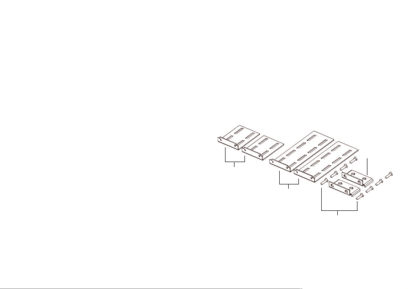
Short autoloader
brackets (part number
74-60604-02)
Long autoloader
brackets (part number
74-60604-01)
8 support bracket
screws
Support brackets
5
Tools
•#2 Phillips screwdriver
Parts
• 4 autoloader brackets (2 long and 2
short, to accommodate different rack
depths)
• 2 support brackets
• 8 10-32 x 1/4 inch button head screws
for the support brackets (4 per support
bracket)
Note: You also need 8 clip nuts and 8
screws, which are not included with your
autoloader but should be included with
your cabinet.
Prepare parts
and tools
2
Sections 2-4 explain
how to prepare and
install the autoloader.
4
Page 4

It takes two people to safely rackmount
your autoloader.
Warning
Before you begin, lower the rack’s leveler
feet and extend the rack’s anti-tip device.
Failure to extend the anti-tip device could
result in personal injury or damage to the
tape autoloader if the rack tips over.
Caution
Do not remove the top cover of the
autoloader during the installation process.
Removing the top cover could result in
damage to the autoloader.
Caution
Ensure that the rack and all equipment
mounted in the rack have a reliable
ground connection. Verify that the total
current of the rack components does not
exceed the current rating of the power
distribution unit or outlet receptacles.
!
!
!
Rackmount the
autoloader
4
7
Choose a
location
3
Choose a location to install the
autoloader.
Caution
Position the autoloader so that no cooling
vents or exhaust from other devices are
located directly in front of the unit; this
helps minimize the amount of foreign
debris entering the tape path. Excessive
dust and debris can damage tapes and
tape drives.
For details about accessing
cartridges and removing magazines,
see the User Manual.
!
6
Page 5
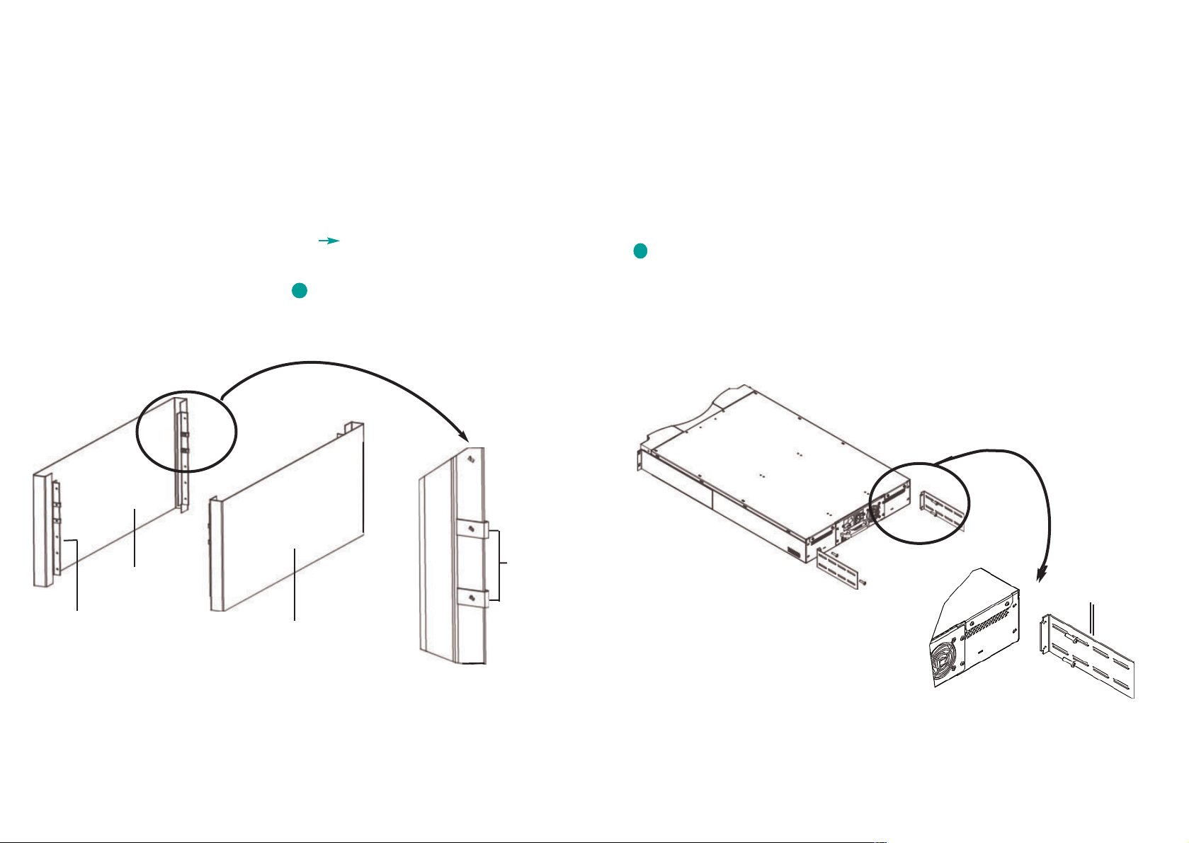
Select the long or short autoloader brackets and attach them to the rear of the
autoloader. (Procedure continues.)
Autoloader
bracket
b
9
Rail in rack
Outer cover
of rack
Outer cover
of rack
Clip nuts
Rackmount the
autoloader,
continued
For details about this procedure, see
the User Manual.
Install two clip nuts, 1.75 inches apart,
onto each of the four rails of the rack,
making sure that you install each pair of
clip nuts at exactly the same level.
a
8
Page 6

Put the autoloader into the rack and do
the following:
1. Position the autoloader in the rack so
that each autoloader bracket rests on a
support bracket. Each autoloader
bracket should slide along the lip of the
support bracket. (Procedure continues.)
Autoloader bracket
Support bracket
d
11
Rackmount the
autoloader,
continued
c
Attach one support bracket to each rear
rail, loosely installing the screws through
the clip nuts. Make sure that you attach
the side of the support bracket that has
only two holes, and do not tighten the
screws yet. You will tighten the screws in
Step h.
Outer cover of rack
Rear rail in rack
Support bracket
10
Page 7

Loosely install the four screws that
connect the support brackets (two
screws per support bracket) to the
autoloader brackets.
e
Verify that the autoloader is level.
Adjust as needed.
Tighten the four screws that attach the
two front ears to the front rails.
Tighten the four screws that connect
the two support brackets to the two
autoloader brackets.
Tighten the four screws that connect
the two support brackets to the two
rear rails.
f
g
h
i
Autoloader bracket
Support bracket
13
Rackmount the
autoloader,
continued
2. Slide the autoloader in place so that
the front ears of the autoloader align
with the front clip nuts. Then loosely
install the four screws that connect the
two support brackets to the two front
rails.
Front rail
Front ear
12
Page 8

e
f
g
If the autoloader will be the last device
on the SCSI bus, install the supplied
SCSI terminator to the remaining port
that is on the autoloader/DCA and then
tighten the screws.
Attach the other end of the SCSI cable
to the SCSI host adapter card.
Power back on any peripheral devices
that you powered off in Step b.
Double-stacked SCSI connector
Note: Do not power on the host computer at this time. You must configure the
autoloader for SCSI and Ethernet prior to
powering on the host.
15
5
Make the SCSI
connection
Caution
When installing cables, be careful not to
damage the SCSI pins on the connectors.
Damaged pins will cause the connection
to fail.
If the host computer is connected to a
network, check with the system administrator before turning off power.
Properly power off all peripheral devices
connected to the host computer.
Power off the host computer.
Install the supplied 68-pin SCSI cable to
the double-stacked SCSI connector that is
on the back of the autoloader/DCA and
tighten the screws. You can install the
SCSI cable in either port.
Note: Notice that the connector on the
end of the cable is offset. Make sure that
you install it with the correct orientation
so that you can fit a terminator or another cable in the other port.
!
d
a
b
c
Sections 5-9 explain
how to set up the
autoloader.
14
Page 9

7
Power on the
autoloader
Push the power switch on the back
of the autoloader to the on position
(the 1 is pressed).
When you first power on the
autoloader, it automatically runs a
Power On Self Test (POST). During
the POST, the left (green) LED flashes. After the POST, the left (green)
and right (amber) LED flash alternately.
Wait while the autoloader performs
its power-on sequence. During this
time, the following activities occur:
• The LCD displays the model and
firmware.
• The LCD displays the tests being
performed as part of the internal
power-on.
Note: If the autoloader displays a
warning message, press Escape to
clear the message.
• The autoloader performs a calibration and magazine element status.
The Ready LED flashes green. A +
appears in the upper right corner
of the LCD while calibration is in
progress.
When the power-on sequence completes and the autoloader is ready,
the LCD displays a list of the
autoloader options that are present
and the Ready LED is steady green.
Note: If there is a warning message
indicating a change, you may need to
press Escape to clear the message.
Note: After the first time you power
on the autoloader, you should use
the switch on the front to power on
and off the autoloader.
a
b
17
6
Connect the
power cord
Note: The first time you power on the
autoloader, do not power on the host.
Make sure that the power switch on the
back of the autoloader is off (the 0 is
pressed).
Connect the female end of the power
cord to the power connector on the back
of the autoloader.
Plug the male end of the power cord into
the power source.
a
b
c
16
Page 10

9
Set the
Ethernet
Ethernet is the method that the
autoloader uses to access a network.
The Ethernet connection is how you
access the Web Administration to
modify the SuperLoader configurations, such as the IP address. Each
Ethernet device must have a unique IP
address.
Use the front panel to determine and
modify the static IP address or set the
SuperLoader to a dynamic address.
If you are not using a dynamic address,
you must set the IP address and
Subnet mask.
For more details, see the User
Manual.
19
8
Set the SCSI ID
Each SCSI device that is attached to a
server or workstation must have a unique
SCSI ID. The SuperLoader is set to a
default SCSI ID of 5. Use the front panel
or Web Administration to change the SCSI
ID if necessary.
For details about setting the SCSI ID,
see the User Manual.
18
Page 11

Scroll to Right Magazine or Left
Magazine and press Enter to eject that
magazine.
If the front panel requests a password,
the default password is 000000. If you
are using the Web Administration, the
default passwords are
Username = guest
password = guest
The magazine selected will be released
and can be removed.
Caution
To prevent damage to the autoloader or
the magazine, use both hands when
removing the magazine from the
autoloader, supporting the entire length
of the magazine.
Grasp the magazine by the handle with
one hand and slide it out, supporting it
underneath with the other hand.
!
d
c
Note: When you eject a magazine, you
must fully remove it or fully re-install it
before powering off the autoloader.
21
Use magazines
and magazine
blanks
This section explains
how to correctly
handle magazines
and cartridges.
The Autoloader will not run unless both
magazine openings are properly closed.
One way that you can close the openings
is to use two magazines. If you use only
one magazine, then you must fill the
other magazine opening with a magazine
blank for the unit to become operational.
For instructions about how to
assemble a magazine blank, provided the one you received is not
assembled, see the User Manual.
Eject a magazine
When you want to remove several
cartridges at once, eject the magazine(s)
first.
On the LCD, press Enter and then scroll to
Commands. Press Enter again to select
Commands.
Scroll to Eject and press Enter.
a
b
20
Page 12

Load and unload cartridges
from a fully ejected magazine
There are two handles located on both
ends of the magazine. Move the slots
within the magazine by using these two
handles. You can use the two openings
along the top of the magazine and the
four openings along the bottom of the
magazine to load and unload cartridges
from the eight slots within each magazine.
Handle
Handle
View of right side of right magazine
23
Use magazines
and magazine
blanks,
continued
Install a magazine
For detailed instructions, see the
User Manual.
Grasp the magazine by the handle with
one hand and support it underneath with
the other hand.
Push the magazine in until it clicks and
locks into place. Make sure that you position the magazine correctly; it should slide
smoothly. If the magazine does not slide
all the way in, verify that the magazine is
properly oriented to the autoloader. If the
magazine is backwards or upside down, it
will not slide and lock into place.
a
b
22
Page 13

b
Properly orient the cartridge.
Note: There is a keying feature in each
slot that only allows you to fully insert the
cartridge one way.
25
Fully insert the cartridge into the slot.
When pushing the cartridge into the slot,
you will feel a small resistance until the
cartridge is properly latched into the slot.
All forward progress stops when the cartridge is fully inserted.
You can remove a cartridge in the same
manner as you insert it. Use the handles
to center the desired slot(s) in the openings on the side of the magazine. Using
your thumb and index finger, pull out the
cartridge. You will feel a small resistance
but continue to pull the cartridge until it
frees.
c
Identify a slot
Each slot has an identification mark that
is exposed when the slots are on the
upper section of the magazine. You can
see the identification mark on the top side
of the magazine.
Each slot has a unique identification number that corresponds to the side on which
the magazine is operating. If the magazine is operating on the left side, the slots
are numbered L1 through L8. If the magazine is operating on the right side, the
slots are numbered R9 through R16.
For a visual representation, see the
User Manual.
Use magazines
and magazine
blanks,
continued
Caution
To load and unload cartridges, it is recommended that you fully remove the magazine. If the magazine is not fully removed,
do not rotate the magazine.
!
To load cartridges in the magazine, center
a slot within one of the six openings
located on the side of the magazine.
a
Orientation mark that
shows which way is up
Correct orientation of cartridge
relative to the magazine
24
Page 14

 Loading...