


 Loading...
TM8100 Mobile Radios
TM8200 Mobile Radios
Installation Guide
MMA-00028-05 · Issue 5 · November 2012

Contact Information
Tait Communications
Corporate Head Office
Tait Limited
P.O. Box 1645
Christchurch
New Zealand
For the address and telephone number of regional offices, refer to our website:www.taitradio.com
Copyright and Trademarks
All information contained in this document is the property of Tait Limited. All rights reserved.
This document may not, in whole or in part, be copied, photocopied, reproduced, translated, stored, or reduced to any electronic medium or machine-readable form, without prior written permission from Tait Limited.
The word TAIT and the TAIT logo are trademarks of Tait Limited.
All trade names referenced are the service mark, trademark or registered trademark of the respective manufacturers.
Disclaimer
There are no warranties extended or granted by this document. Tait Limited accepts no responsibility for damage arising from use of the information contained in the document or of the equipment and software it describes. It is the responsibility of the user to ensure that use of such information, equipment and software complies with the laws, rules and regulations of the applicable jurisdictions.
NZ577009, NZ579051, NZ579364, NZ580361, AU2003281447, AU2004216984, AU2005267973, AU11677/2008, AU13745/2008, CN200930004200.4, CN200930009301.0, CN1031871, CN1070368, EU000915475-0001, EU000915475-0002, GB2386010, GB23865476, GB2413249, GB2413445, US5745840, US7411461, US7649893, US10/523952, US10/546696, US10/ 546697, US10/547964, US10/597339, US11/572700, US29/306491, US61/218015, US61/236663, US61/ 238769, US61/251372.
Environmental Responsibilities
Tait Limited is an environmentally responsible company which supports waste minimization, material recovery and restrictions in the use of hazardous materials.
The European Union’s Waste Electrical and Electronic Equipment (WEEE) Directive requires that this product be disposed of separately from the general waste stream when its service life is over. For more information about how to dispose of your unwanted Tait product, visit the Tait WEEE website at www.taitradio.com/ weee. Please be environmentally responsible and dispose through the original supplier, or contact Tait Limited.
Tait Limited also complies with the Restriction of the Use of Certain Hazardous Substances in Electrical and Electronic Equipment (RoHS) Directive in the European Union.
In China, we comply with the Measures for Administration of the Pollution Control of Electronic Information Products. We will comply with environmental requirements in other markets as they are introduced.
Enquiries and Comments
If you have any enquiries regarding this document, or any comments, suggestions and notifications of errors, please contact your regional Tait office.
Updates of Manual and Equipment
In the interests of improving the performance, reliability or servicing of the equipment, Tait Limited reserves the right to update the equipment or this document or both without prior notice.
Intellectual Property Rights
This product may be protected by one or more patents or designs of Tait Limited together with their international equivalents, pending patent or design applications, and registered trade marks: NZ409837, NZ409838, NZ508806, NZ508807, NZ509242, NZ509640, NZ509959, NZ510496, NZ511155, NZ511421, NZ516280/NZ519742, NZ520650/ NZ537902, NZ521450, NZ522236, NZ524369, NZ524378, NZ524509, NZ524537, NZ524630, NZ530819, NZ534475, NZ534692, NZ535471, NZ537434, NZ546295, NZ547713, NZ569985,
2 |
TM8100/TM8200 Installation Guide |
|
© Tait Limited November 2012 |

Contents
Preface . . . . . . . . . . . . . . . . . . . . . . . . . . . . . . . . . . . . . . . . . . . . . . . . . 5
Scope of Manual. . . . . . . . . . . . . . . . . . . . . . . . . . . . . . . . . . . . . . . . . . . . . . . . . 5
Associated Documentation . . . . . . . . . . . . . . . . . . . . . . . . . . . . . . . . . . . . . . . . . 5
Publication Record. . . . . . . . . . . . . . . . . . . . . . . . . . . . . . . . . . . . . . . . . . . . . . . 6
Document Conventions . . . . . . . . . . . . . . . . . . . . . . . . . . . . . . . . . . . . . . . . . . . 7
1 Safety and Regulatory Warnings . . . . . . . . . . . . . . . . . . . . . . . . . . . . |
. 8 |
|
1.1 |
RF Exposure Hazard. . . . . . . . . . . . . . . . . . . . . . . . . . . . . . . . . . . . . . . . |
. 8 |
1.2 |
Vehicle Manufacturer’s Installation Instructions. . . . . . . . . . . . . . . . . . . . . |
. 8 |
1.3 |
MPT 1362 Code of Practice . . . . . . . . . . . . . . . . . . . . . . . . . . . . . . . . . . |
. 8 |
1.4 |
Safe Radio Mounting . . . . . . . . . . . . . . . . . . . . . . . . . . . . . . . . . . . . . . . |
. 9 |
1.5 |
Interference with Vehicular Electronics . . . . . . . . . . . . . . . . . . . . . . . . . . |
. 9 |
1.6 |
Preparation when Drilling Holes . . . . . . . . . . . . . . . . . . . . . . . . . . . . . . . . |
9 |
1.7 |
Radio Installation in Gas or Fuel Tankers . . . . . . . . . . . . . . . . . . . . . . . . . . |
9 |
1.8 |
Vehicles Powered by Liquefied Petroleum Gas . . . . . . . . . . . . . . . . . . . . . |
10 |
1.9 |
Non-standard Radio Installations . . . . . . . . . . . . . . . . . . . . . . . . . . . . . . . |
10 |
1.10 |
Negative Earth Supply. . . . . . . . . . . . . . . . . . . . . . . . . . . . . . . . . . . . . . . |
10 |
2 Preparing the U-Bracket Installation . . . . . . . . . . . . . . . . . . . . . . . . . |
11 |
|
2.1 |
Installation Tools. . . . . . . . . . . . . . . . . . . . . . . . . . . . . . . . . . . . . . . . . . . |
11 |
2.2 |
Checking the Equipment for Completeness . . . . . . . . . . . . . . . . . . . . . . . |
11 |
2.3 |
Power Source and Ignition Control . . . . . . . . . . . . . . . . . . . . . . . . . . . . . |
13 |
3 Installing the Radio . . . . . . . . . . . . . . . . . . . . . . . . . . . . . . . . . . . . . |
14 |
|
3.1 Mounting and Removing the Control Head. . . . . . . . . . . . . . . . . . . . . . . 14 3.2 Selecting the Mounting Position . . . . . . . . . . . . . . . . . . . . . . . . . . . . . . . 16 3.3 Mounting the U-Bracket. . . . . . . . . . . . . . . . . . . . . . . . . . . . . . . . . . . . . 17 3.4 Installing the Antenna . . . . . . . . . . . . . . . . . . . . . . . . . . . . . . . . . . . . . . . 18 3.5 Connecting the Power Cable to the Power Source . . . . . . . . . . . . . . . . . . 19 3.6 Connecting a Remote Speaker . . . . . . . . . . . . . . . . . . . . . . . . . . . . . . . . 21 3.7 Connecting to the Auxiliary Connector (Ignition Signal, Emergency Switch,
External Alert Devices) . . . . . . . . . . . . . . . . . . . . . . . . . . . . . . . . . . . . . . 22 3.8 Installing the Radio. . . . . . . . . . . . . . . . . . . . . . . . . . . . . . . . . . . . . . . . . 27 3.9 Installing the Microphone . . . . . . . . . . . . . . . . . . . . . . . . . . . . . . . . . . . . 28 3.10 Checking the Installation . . . . . . . . . . . . . . . . . . . . . . . . . . . . . . . . . . . . . 29 3.11 Blank Control Head . . . . . . . . . . . . . . . . . . . . . . . . . . . . . . . . . . . . . . . . 30 3.12 RJ45 Control Head. . . . . . . . . . . . . . . . . . . . . . . . . . . . . . . . . . . . . . . . . 31
4 Installation Options . . . . . . . . . . . . . . . . . . . . . . . . . . . . . . . . . . . . . 32
4.1 Radio Body . . . . . . . . . . . . . . . . . . . . . . . . . . . . . . . . . . . . . . . . . . . . . . 33
4.2 Remote Control Head . . . . . . . . . . . . . . . . . . . . . . . . . . . . . . . . . . . . . . 34
4.3 Dual Control Heads . . . . . . . . . . . . . . . . . . . . . . . . . . . . . . . . . . . . . . . . 35
4.4 Hand-Held Control Head . . . . . . . . . . . . . . . . . . . . . . . . . . . . . . . . . . . . 37
TM8100/TM8200 Installation Guide |
Contents |
3 |
© Tait Limited November 2012 |
|
|
4.5 Dual-Radio System. . . . . . . . . . . . . . . . . . . . . . . . . . . . . . . . . . . . . . . . . 39
4.6 Desktop Power Supply . . . . . . . . . . . . . . . . . . . . . . . . . . . . . . . . . . . . . . 41
Tait Software License Agreement . . . . . . . . . . . . . . . . . . . . . . . . . . . . . . 42
4 |
Contents |
TM8100/TM8200 Installation Guide |
|
|
© Tait Limited November 2012 |

Preface
Scope of Manual
This manual describes the installation of the TM8100/TM8200 mobile radio using the U-bracket, and how to install and connect the microphone, antenna, emergency switch, and external alert device.
The radio can also be installed in many other ways, using different combinations of components and accessories. For information on:
■radio body installation
■remote control head installation
■dual control head installation
■hand-held control head installation
■dual-radio system
■desktop installation
refer to "Installation Options" on page 32, the installation instructions provided with the equipment, and the relevant sections in the service manual.
Some installation options may not be suitable for some models of radio. Consult your nearest Tait Dealer or Customer Service Organization for more information.
For information on installations with two bodies and one control head refer to the TM8260 Installation and Programming Guide (MMA-00041-xx).
Associated Documentation
The following associated documentation is available for this product:
■MTA-00011-xx Safety and Compliance Information
■MMA-00002-xx TM8100 User’s Guide
■MMA-00051-xx TM8235 User’s Guide
■MMA-00003-xx TM8250/TM8255 User’s Guide
■MMA-00040-xx TM8260 User’s Guide
■MMA-00041-xx TM8260 Installation and Programming Guide
■MMA-00005-xx TM8100/TM8200 Service Manual
The characters xx represent the issue number of the documentation.
This publication is also available in French (MMA-00044-xx),
Spanish (MMA-00045-xx), and Chinese (MMA-00048-xx).
TM8100/TM8200 Installation Guide |
Preface |
5 |
© Tait Limited November 2012 |
|
|

Technical notes are published from time to time to describe applications for Tait products, to provide technical details not included in manuals, and to offer solutions for any problems that arise.
All available TM8100/TM8200 product documentation is provided on the CD supplied with the service kit1. Updates may also be published on the Tait support website.
Publication Record
Issue |
Publication Date |
Description |
|
|
|
01 |
August 2005 |
First release |
|
|
|
02 |
July 2006 |
Auxiliary connector information updated |
|
|
TM8235 and TM8260 information added |
|
|
|
03 |
March 2008 |
References to hand-held control head, remote |
|
|
installations, and multi-head/multi-body |
|
|
installations added. |
|
|
Product codes for trigger-base bodies added. |
|
|
Information on antenna gain for 800MHz radios |
|
|
added. |
|
|
Part numbers for fuses corrected. |
|
|
Instructions on avoiding connection to centre tap |
|
|
of two 12V batteries added. |
|
|
Rating for 24V-to-12V converter added. |
|
|
|
04 |
November 2009 |
Installation Options section added. |
|
|
Minor corrections and additions. |
|
|
|
05 |
November 2012 |
New Tait logo |
|
|
|
1.Technical notes are only available in PDF format from the Tait support website. Consult your nearest Tait Dealer.
6 |
Preface |
TM8100/TM8200 Installation Guide |
|
|
© Tait Limited November 2012 |

Document Conventions
Please follow exactly any instruction that appears in the text as an ‘alert’. An alert provides necessary safety information as well as instruction in the proper use of the product. This manual uses the following types of alert:.
>25W
25W
Warning This alert is used when there is a hazardous situation which, if not avoided, could result in death or serious injury.
Caution This alert is used when there is a hazardous situation which, if not avoided, could result in minor or moderate injury.
Notice This alert is used to highlight information that is required to ensure procedures are performed correctly. Incorrectly performed procedures could result in equipment damage or malfunction.
This icon is used to draw your attention to information that may improve your understanding of the equipment or procedure.
Within this manual, the following symbols are used to highlight differences between radios with a transmit power of more than 25W and radios with a transmit power of 25W:
This symbol highlights information that is relevant to radios with a transmit power >25W.
This symbol highlights information that is relevant to radios with a transmit power of 25W.
TM8100/TM8200 Installation Guide |
Preface |
7 |
© Tait Limited November 2012 |
|
|

1 Safety and Regulatory Warnings
This section contains important information on the safe installation of the radio. You must read this information before starting the installation.
You must also read and observe the safety information on radio operation provided in the safety and compliance information and the user’s guide.
1.1RF Exposure Hazard
To comply with FCC RF exposure limits:
For radios with a transmit power >25W:
>25W
■ VHF radios must be installed using an antenna mounted centrally on the vehicle roof, with a gain of 2.15dBi or 5.15dBi.
■ UHF and 800MHz radios must be installed using an antenna mounted either centrally on the roof with a gain of 2.15dBi or 5.65dBi, or centrally mounted on the trunk with a gain of 5.65dBi.
For radios with a transmit power of 25W:
25W
■ The radio must be installed using an externally mounted antenna with a gain of either 2.15dBi or 5.15dBi.
In all cases, the antenna must not be mounted at a location such that any person or persons can come closer than 35 inches (0.9m) to the antenna.
1.2Vehicle Manufacturer’s Installation Instructions
Installation of this product in a vehicle must be performed according to the instructions provided by the vehicle manufacturer. For more information, refer to the vehicle manufacturer’s website or contact the vehicle manufacturer’s dealer.
1.3MPT 1362 Code of Practice
Mobile radios should be installed in accordance with the MPT 1362 Code of Practice.
8 |
Safety and Regulatory Warnings |
TM8100/TM8200 Installation Guide |
|
|
© Tait Limited November 2012 |

1.4Safe Radio Mounting
Warning Mount the radio securely so that it will not break loose in the event of a collision. An unsecured radio is dangerous to the vehicle occupants.
■Mount the radio and the microphone where they will not interfere with:
■the deployment of passenger airbags
■the vehicle operator controls
■the vehicle operator’s view
■Do not mount the radio vertically, with the control head facing down. This will violate compliance with the standards UL/CSA/EN 60950, Safety of Information Technology Equipment.
1.5Interference with Vehicular Electronics
Warning Some vehicular electronic devices may be prone to malfunction due to the lack of protection from RF energy when your radio is transmitting.
Examples of vehicular electronic devices that may be affected by RF energy are:
■electronic fuel injection systems
■electronic anti-skid braking systems
■electronic cruise control systems
■indicators
If the vehicle contains such equipment, consult the vehicle manufacturer or dealer to determine whether these electronic circuits will perform normally when the radio is transmitting.
1.6Preparation when Drilling Holes
Warning When drilling holes in the vehicle, check that drilling at the selected points will not damage existing wiring, fuel tanks, fuel and brake lines, or battery cables.
1.7Radio Installation in Gas or Fuel Tankers
Special conditions must be observed when installing a radio on gas and fuel tankers. Consult your radio provider or Tait-accredited service center for more details.
TM8100/TM8200 Installation Guide |
Safety and Regulatory Warnings |
9 |
© Tait Limited November 2012 |
|
|
1.8Vehicles Powered by Liquefied Petroleum Gas
Warning Radio installation in vehicles powered by LPG (liquefied petroleum gas) with the LPG container in a sealed-off space within the interior of the vehicle must conform to the National Fire Protection Association Standard NFPA 58.
This standard states that the radio equipment installation must meet the following requirements:
■The space containing the radio equipment shall be isolated by a seal from the space containing the LPG container and its fitting.
■Outside filling connections shall be used for the LPG container and its fittings.
■The LPG container space shall be vented to the outside of the vehicle.
1.9Non-standard Radio Installations
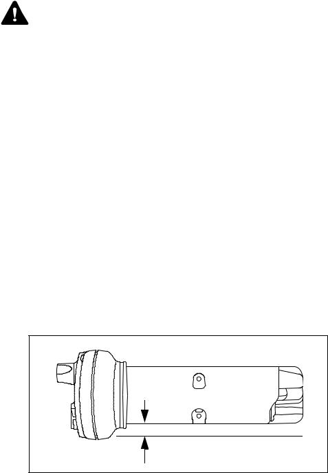
The installation U-bracket described in this guide has been designed so that there is enough airflow around the radio to provide cooling.
If a non-standard installation method is used, care must be taken that sufficient heat can be dissipated from the heatsink fins and the ridged bottom surface of the radio.
For this to be achieved, there must be a gap of more than 3/8 inch (10 mm) between the bottom surface of the radio chassis and the mounting surface. This is illustrated in the following diagram (TM8200 radio shown):
3/8 inch (10 mm) |
mounting surface |
1.10Negative Earth Supply
The radios are designed to operate only in a negative earth system.
10 |
Safety and Regulatory Warnings |
TM8100/TM8200 Installation Guide |
|
|
© Tait Limited November 2012 |
2 Preparing the U-Bracket Installation
This section contains the following information:
■installation tools
■checking the equipment for completeness
■choosing an installation configuration
2.1Installation Tools
The following tools are required to install the radio:
■drill and drill bits
■Pozidriv screwdriver
■5/16 inch (8mm) socket
■RF connector crimp tool
■fuse crimp tool
■in-line RF power meter capable of measuring forward and reflected power at the operating frequency of the radio
2.2Checking the Equipment for Completeness
Unpack the radio and check that you have the following:
1.A radio body with one of the following product codes:
>25W 25W
TM8100:
■TMAB12 standard 25W radio
■TMAB13 trigger-base 25W radio
■TMAB14 standard >25W radio
TM8200:
■TMAB22 standard 25W radio
■TMAB23 trigger-base 25W radio
■TMAB24 standard >25W radio
2.A control head with one of the following product codes:
TM8100:
■TMAC10 blank control head (TM8105 radio)
■TMAC20 2-digit display control head (TM8115 radio)
■TMAC50 1-digit-display control head (TM8110 radio)
TM8200:
■TMAC30 RJ45 control head (TM8252 radio)
■TMAC40 or TMAC42 graphical-display control head (TM8250 and TM8255 radios)
TM8100/TM8200 Installation Guide |
Preparing the U-Bracket Installation |
11 |
© Tait Limited November 2012 |
|
|

>25W 25W
>25W 25W
Installation Kit
Options
■TMAC60 3-digit-display control head (TM8235 radio)
■TMAC70 hand-held control head (TM8254 radio), with TMAC34 remote control head, and TMAA10-06 remote speaker (>25W radio) or TMAA10-03 remote speaker (25W radio)
The TMAC31, TMAC32 and TMAC34 remote interfaces are similar in appearance to the TMAC30 RJ45 control head of the telemetry radio. However, their electrical characteristics and signals are different. For more information, refer to the installation instructions provided with the remote kits.
3.TMAA02-01 microphone, TMAA02-08 keypad microphone including microphone clip and screws (not required for the TM8105, TM8252 or TM8254 radio)
4.A TMAA03-17 installation kit (>25W radio) or TMAA03-01
installation kit (25W radio), consisting of the following items:
■U-bracket
■thumbscrews
■self-drilling screws and washers
■power cable with DC connector
■fuses
■in-line fuse holders
■receptacles for a remote speaker (remote speaker not included)
■antenna connector
Refer to "Installation Kit Options" below.
Warning Danger of fire! The radio’s protection mechanisms rely on the correct fuses on both the negative and positive power supply leads being present. Failure to fit the correct fuses may result in fire or damage to the radio.
The correct fuse types are:
■>25W radios: 20A fuses (Tait IPN 265-00010-81)
■25W radios: 10A fuses (Tait IPN 265-00010-80)
Installation kits are also available without the U-bracket included and with other antenna connector options. Consult your nearest Tait Dealer or Customer Service Organization for more information.
12 |
Preparing the U-Bracket Installation |
TM8100/TM8200 Installation Guide |
|
|
© Tait Limited November 2012 |

2.3Power Source and Ignition Control
Direct Connection to the Power Source
Installation without Ignition Signal
The radio allows for different installation configurations for vehicles with respect to ignition signal and standby current. The installation configurations described below are based on the following hardware link configuration:
■hardware link 1 (+13.8V battery power sense): fitted
■hardware link 2 (ignition sense): fitted
For more information on the hardware links, refer to Table 3.4 on page 24 and to the service manual.
The radio’s power cable must always be connected directly to the power source (battery).
Notice Although it is possible to connect the radio in line with the vehicle ignition, this is not recommended, as it may draw too much current and damage the vehicle wiring and steering column or ignition switch. This may also cause the supply voltage of the radio to drop below the specified level.
The radio can always be turned on and off using the on/off button, independent of the ignition signal.
Connect the power cable directly to the power source as described in "Connecting the Power Cable to the Power Source" on page 19.
If hardware link 1 is fitted (factory default) and the ignition signal is not used, the standby current is approximately 50mA. To reduce the standby current to <3mA either:
Installation with Ignition Signal
■remove hardware link 1, or
■connect pin 4 (AUX GPI3) to pin 15 (AGND) of the auxiliary connector
With the above two options, the radio always stays off when power is first applied. The radio can only be turned on with the on/off button.
Connect the power cable directly to the power source as described in "Connecting the Power Cable to the Power Source" on page 19.
Connect pin 4 (AUX GPI3) of the auxiliary connector to the ignition signal as described in "Connecting to the Auxiliary Connector (Ignition Signal, Emergency Switch, External Alert Devices)" on page 22.
The AUX GPI3 line must be programmed to ‘Power Sense (Ignition)’ and active to ‘High’. For more information, refer to the online help of the programming application.
The TMAA04-05 ignition sense kit provides a suitable mating plug for the radio’s auxiliary connector. The plug includes wiring for the the ignition signal and analog ground.
TM8100/TM8200 Installation Guide |
Preparing the U-Bracket Installation |
13 |
© Tait Limited November 2012 |
|
|

3 Installing the Radio
This section contains the following information:
■mounting and removing the control head
■selecting the mounting position
■mounting the U-bracket
■installing the antenna
■connecting the power cable to the power source
■connecting a remote speaker
■connecting to the auxiliary connector (ignition signal, emergency switch, external alert devices)
■installing the radio
■installing the microphone
■checking the installation
■blank control head
■RJ45 control head
For information on other types of installation, refer to "Installation Options" on page 32, the installation instructions provided with the equipment, and the relevant sections in the service manual.
3.1Mounting and Removing the Control Head
Mounting the
Control Head
Notice The control head contains devices which can be damaged by static discharges. Always install or remove the control head in a static-safe environment. For information on antistatic precautions, go to the Electrostatic Discharge Association (ESD) website, http://www.esda.org.
The control head and its connection loom are delivered separately from the radio body. Before installing the radio, the control head should be mounted on the radio body.
The orientation of the radio body determines which way up the control head is mounted on the radio body.
Notice It may be necessary to mount the radio upside down to maintain a gap of more than 3/8 inch (10 mm) for air circulation between the underside of the radio body and the mounting surface.
14 |
Installing the Radio |
TM8100/TM8200 Installation Guide |
|
|
© Tait Limited November 2012 |

Figure 3.1 Mounting the control head
Removing the
Control Head
1.Plug the control-head loom onto the control-head connector.
2.Place one edge of the control head on either the top or bottom pair of snap features on the front of the radio body, then rotate to snap the opposite edge into place.
Notice During this procedure, take care that the control-head seal is not damaged. Damage to this seal reduces environmental protection.
Figure 3.2 Removing the control head
control head |
lever point |
control-head |
seal |
indication of |
lever point |
On the underside of the radio, two lever points are indicated on the radio body by a dot-dash-dot pattern (

 ). The lever point is between the control-head seal and the control head.
1.At either of the lever points, insert a 3/16 inch (5 mm) flat-bladed screwdriver between the control head and the control-head seal.
2.Use the screwdriver to lift the control head off the snap feature, then repeat in the other position. The control head can now be removed from the radio body.
TM8100/TM8200 Installation Guide |
Installing the Radio |
15 |
© Tait Limited November 2012 |
|
|
Loading...