


TB9100 Base Station
P25 CG Console Gateway
P25 TAG Trunked Analog Gateway
Installation and Operation Manual
MBA-00002-15 · Issue 15 · March 2014

Contact Information
Tait Communications
Corporate Head Office
Tait Limited
P.O. Box 1645
Christchurch
New Zealand
For the address and telephone number of regional offices, refer to our website:www.taitradio.com
Copyright and Trademarks
All information contained in this document is the property of Tait Limited. All rights reserved.
This document may not, in whole or in part, be copied, photocopied, reproduced, translated, stored, or reduced to any electronic medium or machine-readable form, without prior written permission from Tait Limited.
The word TAIT and the TAIT logo are trademarks of Tait Limited.
All trade names referenced are the service mark, trademark or registered trademark of the respective manufacturers.
Disclaimer
There are no warranties extended or granted by this document. Tait Limited accepts no responsibility for damage arising from use of the information contained in the document or of the equipment and software it describes. It is the responsibility of the user to ensure that use of such information, equipment and software complies with the laws, rules and regulations of the applicable jurisdictions.
Enquiries and Comments
If you have any enquiries regarding this document, or any comments, suggestions and notifications of errors, please contact your regional Tait office.
Updates of Manual and Equipment
In the interests of improving the performance, reliability or servicing of the equipment, Tait Limited reserves the right to update the equipment or this document or both without prior notice.
Intellectual Property Rights
This product may be protected by one or more patents or designs of Tait Limited together with their international equivalents, pending patent or design applications, and registered trade marks: NZ409837, NZ409838, NZ415277, NZ415278, NZ508806, NZ511155, NZ516280/NZ519742, NZ521450, NZ524369, NZ524378, NZ524509, NZ524537, NZ530819, NZ534475, NZ534692, NZ547713, NZ569985, NZ577009, NZ579051, NZ579364, NZ580361, NZ584534, NZ586889, NZ592624, NZ593887, NZ593888, NZ600346, NZ601933 ,
2
NZ607046, NZ607046, NZ610426, NZ610563, NZ612027, NZ613565, NZ615898, NZ615954, AU2004216984, AU321864, AU321868, AU339127, AU339391, CN1031871, CN1070368, CN200930004199.5, CN200930004200.4, CN200930009301.0, EU000915475-0001, EU000915475-0002, GB2413445, US12/870840, US13/082767, US13/185498, US13/465664, US13/ 542062, US13/542147, US13/763531, US13/896969, US14/032876, US29/401234, US29/401235, US5745840, US640974, US640977, US7411461, US7758996, US7937661, US8301682.
This product may also be made under license under one or more of the following U.S. Patents: 4,590,473 4,636,791 4,716,407 4,972,460 5,146,497 5,148,482 5,164,986 5,185,795 5,185,796 5,271,017 5,377,229 5,502,767.
The IMBE™ voice coding Technology embodied in this product is protected by intellectual property rights including patent rights, copyrights and trade secrets of Digital Voice Systems, Inc. This voice coding Technology is licensed solely for use within this Communications Equipment. The user of this Technology is explicitly prohibited from attempting to decompile, reverse engineer, or disassemble the Object Code, or in any other way convert the Object Code into a human-readable form. Protected by U.S. Patents 5,870,405, 5,826,222, 5,754,974, 5,701,390, 5,715,365, 5,649,050, 5,630,011, 5,581,656, 5,517,511, 5,491,772, 5,247,579, 5,226,084 and 5,195,166.
Environmental Responsibilities
Tait Limited is an environmentally responsible company which supports waste minimization, material recovery and restrictions in the use of hazardous materials.
The European Union’s Waste Electrical and Electronic Equipment (WEEE) Directive requires that this product be disposed of separately from the general waste stream when its service life is over. For more information about how to dispose of your unwanted Tait product, visit the Tait WEEE website at www.taitradio.com/ weee. Please be environmentally responsible and dispose through the original supplier, or contact Tait Limited.
Tait Limited also complies with the Restriction of the Use of Certain Hazardous Substances in Electrical and Electronic Equipment (RoHS) Directive in the European Union.
In China, we comply with the Measures for Administration of the Pollution Control of Electronic Information Products. We will comply with environmental requirements in other markets as they are introduced.
TB9100/P25 CG/P25 TAG Installation and Operation Manual © Tait Limited March 2014

Contents
Preface . . . . . . . . . . . . . . . . . . . . . . . . . . . . . . . . . . . . . . . . . . . . . . . . . . . . . 7
Scope of Manual . . . . . . . . . . . . . . . . . . . . . . . . . . . . . . . . . . . . . . . . . . . . . . . . . . . . 7
Document Conventions . . . . . . . . . . . . . . . . . . . . . . . . . . . . . . . . . . . . . . . . . . . . . . . 7
Associated Documentation . . . . . . . . . . . . . . . . . . . . . . . . . . . . . . . . . . . . . . . . . . . . . 8
Publication Record . . . . . . . . . . . . . . . . . . . . . . . . . . . . . . . . . . . . . . . . . . . . . . . . . . 9
1 Description. . . . . . . . . . . . . . . . . . . . . . . . . . . . . . . . . . . . . . . . . . . . . . . 11
1.1 Features . . . . . . . . . . . . . . . . . . . . . . . . . . . . . . . . . . . . . . . . . . . . . . . . . . . . . . 12
1.2 Base Station and Gateway . . . . . . . . . . . . . . . . . . . . . . . . . . . . . . . . . . . . . . . . . 12
1.3 Modules . . . . . . . . . . . . . . . . . . . . . . . . . . . . . . . . . . . . . . . . . . . . . . . . . . . . . . 13
Base Station Reciter. . . . . . . . . . . . . . . . . . . . . . . . . . . . . . . . . . . . . . . . . . . 14
Gateway Modules . . . . . . . . . . . . . . . . . . . . . . . . . . . . . . . . . . . . . . . . . . . . 14
Power Amplifier . . . . . . . . . . . . . . . . . . . . . . . . . . . . . . . . . . . . . . . . . . . . . 15
Power Management Unit . . . . . . . . . . . . . . . . . . . . . . . . . . . . . . . . . . . . . . . 15
Front Panel . . . . . . . . . . . . . . . . . . . . . . . . . . . . . . . . . . . . . . . . . . . . . . . . . 16
Control Panel . . . . . . . . . . . . . . . . . . . . . . . . . . . . . . . . . . . . . . . . . . . . . . . 16
Subrack . . . . . . . . . . . . . . . . . . . . . . . . . . . . . . . . . . . . . . . . . . . . . . . . . . . . 16
1.4 Frequency Bands and Sub-bands . . . . . . . . . . . . . . . . . . . . . . . . . . . . . . . . . . . . 17
1.5 Product Options . . . . . . . . . . . . . . . . . . . . . . . . . . . . . . . . . . . . . . . . . . . . . . . . 17
Base Station/Repeater . . . . . . . . . . . . . . . . . . . . . . . . . . . . . . . . . . . . . . . . . 17
12V DC PA-Only Base Station/Repeater . . . . . . . . . . . . . . . . . . . . . . . . . . . 18
Receive-only Base Station . . . . . . . . . . . . . . . . . . . . . . . . . . . . . . . . . . . . . . 18
Console Gateway. . . . . . . . . . . . . . . . . . . . . . . . . . . . . . . . . . . . . . . . . . . . . 18
Trunked Analog Gateway. . . . . . . . . . . . . . . . . . . . . . . . . . . . . . . . . . . . . . . 18
1.6 Applications . . . . . . . . . . . . . . . . . . . . . . . . . . . . . . . . . . . . . . . . . . . . . . . . . . . 19 Repeater . . . . . . . . . . . . . . . . . . . . . . . . . . . . . . . . . . . . . . . . . . . . . . . . . . . 19 Line-Connected Base Station . . . . . . . . . . . . . . . . . . . . . . . . . . . . . . . . . . . . 19 Channel Group . . . . . . . . . . . . . . . . . . . . . . . . . . . . . . . . . . . . . . . . . . . . . . 19 Trunking Control or Traffic Channel . . . . . . . . . . . . . . . . . . . . . . . . . . . . . . 19 Simulcast . . . . . . . . . . . . . . . . . . . . . . . . . . . . . . . . . . . . . . . . . . . . . . . . . . . 20 P25 Linking. . . . . . . . . . . . . . . . . . . . . . . . . . . . . . . . . . . . . . . . . . . . . . . . . 20 Data Gateway . . . . . . . . . . . . . . . . . . . . . . . . . . . . . . . . . . . . . . . . . . . . . . . 20 Console Gateway. . . . . . . . . . . . . . . . . . . . . . . . . . . . . . . . . . . . . . . . . . . . . 21 Trunked Analog Gateway. . . . . . . . . . . . . . . . . . . . . . . . . . . . . . . . . . . . . . . 21
1.7 Theory of Operation. . . . . . . . . . . . . . . . . . . . . . . . . . . . . . . . . . . . . . . . . . . . . 21
Signal Paths . . . . . . . . . . . . . . . . . . . . . . . . . . . . . . . . . . . . . . . . . . . . . . . . . 23
Run and Standby Modes . . . . . . . . . . . . . . . . . . . . . . . . . . . . . . . . . . . . . . . 24
Dual Mode . . . . . . . . . . . . . . . . . . . . . . . . . . . . . . . . . . . . . . . . . . . . . . . . . 24
Intermodule Communications . . . . . . . . . . . . . . . . . . . . . . . . . . . . . . . . . . . 26
Power Management . . . . . . . . . . . . . . . . . . . . . . . . . . . . . . . . . . . . . . . . . . . 27
Power Distribution . . . . . . . . . . . . . . . . . . . . . . . . . . . . . . . . . . . . . . . . . . . 27
Front Panel Fans . . . . . . . . . . . . . . . . . . . . . . . . . . . . . . . . . . . . . . . . . . . . . 29
TB9100/P25 CG/P25 TAG Installation and Operation Manual |
3 |
© Tait Limited March 2014 |
|
2 General Safety and Regulatory Information. . . . . . . . . . . . . . . . . . . . . . . . . 31
2.1 Personal Safety . . . . . . . . . . . . . . . . . . . . . . . . . . . . . . . . . . . . . . . . . . . . . . . . . 31 Unpacking and Moving the Equipment . . . . . . . . . . . . . . . . . . . . . . . . . . . . 31 Lethal Voltages . . . . . . . . . . . . . . . . . . . . . . . . . . . . . . . . . . . . . . . . . . . . . . 31 AC Power Connection . . . . . . . . . . . . . . . . . . . . . . . . . . . . . . . . . . . . . . . . 32 Explosive Environments. . . . . . . . . . . . . . . . . . . . . . . . . . . . . . . . . . . . . . . . 32 Proximity to RF Transmissions . . . . . . . . . . . . . . . . . . . . . . . . . . . . . . . . . . 32 High Temperatures . . . . . . . . . . . . . . . . . . . . . . . . . . . . . . . . . . . . . . . . . . . 32 LED Safety (EN60825-1) . . . . . . . . . . . . . . . . . . . . . . . . . . . . . . . . . . . . . . 32
2.2 Equipment Safety . . . . . . . . . . . . . . . . . . . . . . . . . . . . . . . . . . . . . . . . . . . . . . . 33 Installation and Servicing Personnel . . . . . . . . . . . . . . . . . . . . . . . . . . . . . . . 33 Preventing Damage to the PA . . . . . . . . . . . . . . . . . . . . . . . . . . . . . . . . . . . 33 ESD Precautions . . . . . . . . . . . . . . . . . . . . . . . . . . . . . . . . . . . . . . . . . . . . . 33 Anti-tampering Devices . . . . . . . . . . . . . . . . . . . . . . . . . . . . . . . . . . . . . . . . 34
2.3 Environmental Conditions . . . . . . . . . . . . . . . . . . . . . . . . . . . . . . . . . . . . . . . . 34
Operating Temperature Range. . . . . . . . . . . . . . . . . . . . . . . . . . . . . . . . . . . 34
Humidity . . . . . . . . . . . . . . . . . . . . . . . . . . . . . . . . . . . . . . . . . . . . . . . . . . 34
Dust and Dirt . . . . . . . . . . . . . . . . . . . . . . . . . . . . . . . . . . . . . . . . . . . . . . . 34
2.4 Regulatory Information . . . . . . . . . . . . . . . . . . . . . . . . . . . . . . . . . . . . . . . . . . 35
Distress Frequencies. . . . . . . . . . . . . . . . . . . . . . . . . . . . . . . . . . . . . . . . . . . 35
Compliance Standards . . . . . . . . . . . . . . . . . . . . . . . . . . . . . . . . . . . . . . . . . 35
FCC Compliance . . . . . . . . . . . . . . . . . . . . . . . . . . . . . . . . . . . . . . . . . . . . 35
FCC Narrowbanding Regulations . . . . . . . . . . . . . . . . . . . . . . . . . . . . . . . . 36
Unauthorized Modifications. . . . . . . . . . . . . . . . . . . . . . . . . . . . . . . . . . . . . 36
Health, Safety and Electromagnetic Compatibility in Europe . . . . . . . . . . . . . 36
3 Installation . . . . . . . . . . . . . . . . . . . . . . . . . . . . . . . . . . . . . . . . . . . . . . . 39
3.1 Before You Begin . . . . . . . . . . . . . . . . . . . . . . . . . . . . . . . . . . . . . . . . . . . . . . 39
Equipment Security . . . . . . . . . . . . . . . . . . . . . . . . . . . . . . . . . . . . . . . . . . . 39
Grounding and Lightning Protection . . . . . . . . . . . . . . . . . . . . . . . . . . . . . . 39
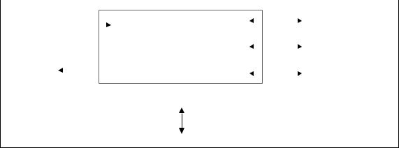
Equipment Ventilation. . . . . . . . . . . . . . . . . . . . . . . . . . . . . . . . . . . . . . . . . 40
Ambient Air Temperature Sensor . . . . . . . . . . . . . . . . . . . . . . . . . . . . . . . . . 40
Cabinet and Rack Ventilation . . . . . . . . . . . . . . . . . . . . . . . . . . . . . . . . . . . 40
3.2 Installing and Setting up the CSS. . . . . . . . . . . . . . . . . . . . . . . . . . . . . . . . . . . . 43 Setting up CSS Access Codes . . . . . . . . . . . . . . . . . . . . . . . . . . . . . . . . . . . . 43 PC Recommendations. . . . . . . . . . . . . . . . . . . . . . . . . . . . . . . . . . . . . . . . . 44
3.3 Unpacking and Moving the Subrack . . . . . . . . . . . . . . . . . . . . . . . . . . . . . . . . . 44
3.4 Setting Up on the Bench . . . . . . . . . . . . . . . . . . . . . . . . . . . . . . . . . . . . . . . . . 46 Confirming Operation . . . . . . . . . . . . . . . . . . . . . . . . . . . . . . . . . . . . . . . . . 47 Connecting the CSS for the First Time and Setting the IP Address. . . . . . . . . 48 Finding a Lost or Forgotten IP Address. . . . . . . . . . . . . . . . . . . . . . . . . . . . . 49 Customizing the Configuration . . . . . . . . . . . . . . . . . . . . . . . . . . . . . . . . . . 50 Recommended CSS Settings for Dual Base Stations . . . . . . . . . . . . . . . . . . . 50 Changing the Root Password. . . . . . . . . . . . . . . . . . . . . . . . . . . . . . . . . . . . 52 Short Tuning Procedure . . . . . . . . . . . . . . . . . . . . . . . . . . . . . . . . . . . . . . . 53 Checking the Modulation Fidelity . . . . . . . . . . . . . . . . . . . . . . . . . . . . . . . . 56 Other Operational Tests. . . . . . . . . . . . . . . . . . . . . . . . . . . . . . . . . . . . . . . . 58
3.5 Installing the Base Station on Site . . . . . . . . . . . . . . . . . . . . . . . . . . . . . . . . . . . 59 Base Stations for Trunked Systems . . . . . . . . . . . . . . . . . . . . . . . . . . . . . . . . 59
4 |
TB9100/P25 CG/P25 TAG Installation and Operation Manual |
|
© Tait Limited March 2014 |
Equipment Required . . . . . . . . . . . . . . . . . . . . . . . . . . . . . . . . . . . . . . . . . . 59
Mounting the Subrack . . . . . . . . . . . . . . . . . . . . . . . . . . . . . . . . . . . . . . . . . 60
3.6 Connecting Up the Base Station . . . . . . . . . . . . . . . . . . . . . . . . . . . . . . . . . . . . 64
Connection Overview . . . . . . . . . . . . . . . . . . . . . . . . . . . . . . . . . . . . . . . . . 64
Connecting AC Power. . . . . . . . . . . . . . . . . . . . . . . . . . . . . . . . . . . . . . . . . 65
Connecting DC Power . . . . . . . . . . . . . . . . . . . . . . . . . . . . . . . . . . . . . . . . 66
Connecting the Auxiliary DC Power Output . . . . . . . . . . . . . . . . . . . . . . . . 68
Connecting RF . . . . . . . . . . . . . . . . . . . . . . . . . . . . . . . . . . . . . . . . . . . . . . 69
Connecting an External Frequency Reference. . . . . . . . . . . . . . . . . . . . . . . . 70
Connecting a 1PPS Source. . . . . . . . . . . . . . . . . . . . . . . . . . . . . . . . . . . . . . 71
Connecting an Antenna Relay . . . . . . . . . . . . . . . . . . . . . . . . . . . . . . . . . . . 72
Connecting the Ethernet Line . . . . . . . . . . . . . . . . . . . . . . . . . . . . . . . . . . . 72
Connecting the Analog Line. . . . . . . . . . . . . . . . . . . . . . . . . . . . . . . . . . . . . 73
Connecting General Purpose Inputs and Outputs . . . . . . . . . . . . . . . . . . . . . 77
4 Operation. . . . . . . . . . . . . . . . . . . . . . . . . . . . . . . . . . . . . . . . . . . . . . . . 79
4.1 Control Panel . . . . . . . . . . . . . . . . . . . . . . . . . . . . . . . . . . . . . . . . . . . . . . . . . . 79
Speaker Operation . . . . . . . . . . . . . . . . . . . . . . . . . . . . . . . . . . . . . . . . . . . . 82
Microphone Operation . . . . . . . . . . . . . . . . . . . . . . . . . . . . . . . . . . . . . . . . 82
4.2 Monitoring with the CSS . . . . . . . . . . . . . . . . . . . . . . . . . . . . . . . . . . . . . . . . . 83
4.3 Monitoring Front Panel Fan Operation . . . . . . . . . . . . . . . . . . . . . . . . . . . . . . . 83
4.4 Module LED Indicators and Switches . . . . . . . . . . . . . . . . . . . . . . . . . . . . . . . . 84
Reciter . . . . . . . . . . . . . . . . . . . . . . . . . . . . . . . . . . . . . . . . . . . . . . . . . . . . 84
PA . . . . . . . . . . . . . . . . . . . . . . . . . . . . . . . . . . . . . . . . . . . . . . . . . . . . 86
PMU . . . . . . . . . . . . . . . . . . . . . . . . . . . . . . . . . . . . . . . . . . . . . . . . . . . . 87
5 Maintenance . . . . . . . . . . . . . . . . . . . . . . . . . . . . . . . . . . . . . . . . . . . . . . 89
6 Troubleshooting . . . . . . . . . . . . . . . . . . . . . . . . . . . . . . . . . . . . . . . . . . . 91
7 Replacing Modules . . . . . . . . . . . . . . . . . . . . . . . . . . . . . . . . . . . . . . . . . 95
7.1 Saving the Base Station’s Configuration . . . . . . . . . . . . . . . . . . . . . . . . . . . . . . . 95
7.2 Preliminary Disassembly . . . . . . . . . . . . . . . . . . . . . . . . . . . . . . . . . . . . . . . . . . 96
7.3 Replacing the Control Panel . . . . . . . . . . . . . . . . . . . . . . . . . . . . . . . . . . . . . . . 98
Configuring the Control Panel Board . . . . . . . . . . . . . . . . . . . . . . . . . . . . . . 99
7.4 Replacing a Reciter . . . . . . . . . . . . . . . . . . . . . . . . . . . . . . . . . . . . . . . . . . . . 101
7.5 Replacing a Power Amplifier . . . . . . . . . . . . . . . . . . . . . . . . . . . . . . . . . . . . . 103
7.6 Replacing a Power Management Unit . . . . . . . . . . . . . . . . . . . . . . . . . . . . . . . 105
7.7 Replacing the Front Panel Fans . . . . . . . . . . . . . . . . . . . . . . . . . . . . . . . . . . . . 106
7.8 Replacing the Module Guide Rails . . . . . . . . . . . . . . . . . . . . . . . . . . . . . . . . . 109
7.9 Replacing the Subrack Interconnect Board . . . . . . . . . . . . . . . . . . . . . . . . . . . |
110 |
Configuring the Subrack Interconnect Board. . . . . . . . . . . . . . . . . . . . . . . . |
112 |
7.10 Final Reassembly . . . . . . . . . . . . . . . . . . . . . . . . . . . . . . . . . . . . . . . . . . . . . . 115
Reprogramming . . . . . . . . . . . . . . . . . . . . . . . . . . . . . . . . . . . . . . . . . . . . 115
Fitting the Front Panel and Powering Up . . . . . . . . . . . . . . . . . . . . . . . . . . 115
TB9100/P25 CG/P25 TAG Installation and Operation Manual |
5 |
© Tait Limited March 2014 |
|
8 Technical Description . . . . . . . . . . . . . . . . . . . . . . . . . . . . . . . . . . . . . . .117
8.1 Mechanical Assembly . . . . . . . . . . . . . . . . . . . . . . . . . . . . . . . . . . . . . . . . . . . 117
8.2 Reciter Module Operation . . . . . . . . . . . . . . . . . . . . . . . . . . . . . . . . . . . . . . . 119
8.3 PA Module Operation . . . . . . . . . . . . . . . . . . . . . . . . . . . . . . . . . . . . . . . . . . 123
8.4 PMU Module Operation . . . . . . . . . . . . . . . . . . . . . . . . . . . . . . . . . . . . . . . . 126
PMU Operation on DC Input . . . . . . . . . . . . . . . . . . . . . . . . . . . . . . . . . . 129
8.5 Control Panel. . . . . . . . . . . . . . . . . . . . . . . . . . . . . . . . . . . . . . . . . . . . . . . . . 132
8.6 System Control Bus . . . . . . . . . . . . . . . . . . . . . . . . . . . . . . . . . . . . . . . . . . . . 135
Appendix A – Interface Pin Assignments . . . . . . . . . . . . . . . . . . . . . . . . . .139
D-range Connector . . . . . . . . . . . . . . . . . . . . . . . . . . . . . . . . . . . . . . . . . . 139 Analog Interface Connection . . . . . . . . . . . . . . . . . . . . . . . . . . . . . . . . . . . 139 Digital Interface Connection . . . . . . . . . . . . . . . . . . . . . . . . . . . . . . . . . . . 139 PMU Auxiliary DC Output . . . . . . . . . . . . . . . . . . . . . . . . . . . . . . . . . . . . 139 DC Input to 12V PA. . . . . . . . . . . . . . . . . . . . . . . . . . . . . . . . . . . . . . . . . 140 Microphone Connection . . . . . . . . . . . . . . . . . . . . . . . . . . . . . . . . . . . . . . 140
Appendix B – Inter-Module Connections . . . . . . . . . . . . . . . . . . . . . . . . . .141
5 or 50W Base Station. . . . . . . . . . . . . . . . . . . . . . . . . . . . . . . . . . . . . . . . 141 100W Base Station . . . . . . . . . . . . . . . . . . . . . . . . . . . . . . . . . . . . . . . . . . 142 12V PA Base Station . . . . . . . . . . . . . . . . . . . . . . . . . . . . . . . . . . . . . . . . . 143 Dual Channel 5 or 50W Base Station . . . . . . . . . . . . . . . . . . . . . . . . . . . . . 144 Five Reciters and One PMU . . . . . . . . . . . . . . . . . . . . . . . . . . . . . . . . . . . 146 Seven Reciters . . . . . . . . . . . . . . . . . . . . . . . . . . . . . . . . . . . . . . . . . . . . . 147
P25 Glossary . . . . . . . . . . . . . . . . . . . . . . . . . . . . . . . . . . . . . . . . . . . . . .149
6 |
TB9100/P25 CG/P25 TAG Installation and Operation Manual |
|
© Tait Limited March 2014 |
Preface
Scope of Manual
This manual primarily describes the TB9100 base station but also includes the P25 CG console gateway and P25 TAG trunked analog gateway. When “base station” is referred to, this generally applies to the console gateway and trunked analog gateway as well. When “reciter” is referred to, this generally applies also to the gateway module.
This manual is intended for use by experienced technicians familiar with installing and operating base station and gateway equipment. It includes a technical description of the equipment, maintenance and troubleshooting information.
Document Conventions
“File > Open” means “click File on the menu bar, then click Open on the list of commands that pops up”. “Monitor > Module Details > Channel Module” means “click the Monitor icon on the toolbar, then in the navigation pane find the Module Details group, and select Channel Module from it”.
Within this manual, four types of alerts may be given to the reader. The following paragraphs illustrate each type of alert and its associated symbol.
Warning This alert is used when there is a hazardous situation which, if not avoided, could result in death or serious injury.
Caution This alert is used when there is a hazardous situation which, if not avoided, could result in minor or moderate injury.
Notice This alert is used to highlight information that is required to ensure procedures are performed correctly. Incorrectly performed procedures could result in equipment damage or malfunction.
This icon is used to draw your attention to information that may improve your understanding of the equipment or procedure.
TB9100/P25 CG/P25 TAG Installation and Operation Manual |
Preface |
7 |
© Tait Limited March 2014 |
|
|
Associated Documentation
The current set of TB9100 product documentation is provided in PDF format on the product CD. Updates are made available on the Tait support web. Print copies of the documentation are available on request.
■TB9100 Specifications Manual (MBA-00014-xx).
■TB9100 Customer Service Software User’s Manual (MBA-00003-xx) and online Help.
■TB9100 Calibration Software User’s Manual (MBA-00004-xx) and online Help.
■TBA0STU/TBA0STP Calibration and Test Unit Operation Manual (MBA-00013-xx).
■TaitNet P25 Conventional Networks System Manual (MBA-00032-xx).
■TaitNet P25 Trunked Networks System Manual (MBA-00045-xx).
■TN9400 P25 Trunked Network System Manual (MNC-00001-xx).
■Safety and Compliance Information (MBA-00012-xx)
The characters xx represent the issue number of the documentation.
Technical notes are published from time to time to describe applications for Tait products, to provide technical details not included in manuals, and to offer solutions for any problems that arise. The product CD includes technical notes that were available at the time of release. Look for new or updated technical notes on Tait’s technical support website.
8 |
Preface |
TB9100/P25 CG/P25 TAG Installation and Operation Manual |
|
|
© Tait Limited March 2014 |
Publication Record
Issue |
Publication Date |
Description |
|
|
|
1 |
July 2004 |
First release |
|
|
|
2 |
January 2005 |
General updates; new photographs; |
|
|
Appendix C added |
|
|
|
3 |
March 2005 |
General updates; Appendix D added |
|
|
|
4 |
August 2005 |
General updates for version 1.2 release; |
|
|
Appendix D removed |
|
|
|
5 |
May 2006 |
General updates for version 2.1 release |
|
|
|
6 |
August 2006 |
General updates for version 2.2 release; |
|
|
H4 frequency band added; control panel |
|
|
updated; P25 CG console gateway |
|
|
added. |
|
|
|
7 |
January 2007 |
General updates for version 3.0. DFSI |
|
|
interface, centralized voting, voter and |
|
|
switch redesign. Modulation fidelity test. |
|
|
Recommendations for preventing |
|
|
damage to the PA. Carrying handles. |
|
|
|
8 |
November 2007 |
Updates for simulcast. Short tuning |
|
|
procedure. |
|
|
|
9 |
January 2009 |
General updates. P25 TAG trunked |
|
|
analog gateway added. Extra |
|
|
information on analog line connections. |
|
|
|
10 |
December 2009 |
General updates. Analog line connection |
|
|
information updated. 12V PA startup |
|
|
voltage changed. Subrack dimension |
|
|
drawing added. |
|
|
|
11 |
September 2010 |
General updates. Data gateway |
|
|
information added. |
|
|
|
12 |
August 2012 |
General updates for version 3.9 release. |
|
|
Information added on compliance |
|
|
standards, PMU fan thresholds, PA |
|
|
power foldback, and reprogramming |
|
|
base stations after replacing modules. |
|
|
|
13 |
November 2012 |
Information added on FCC |
|
|
narrowbanding regulations |
|
|
|
14 |
September 2013 |
Torque setting for SMA connectors |
|
|
reduced. |
|
|
|
15 |
March 2014 |
Information added on recommended |
|
|
CSS settings for dual base stations. |
|
|
PMU fan thresholds updated. |
|
|
Minor additions and corrections. |
|
|
|
TB9100/P25 CG/P25 TAG Installation and Operation Manual |
Preface |
9 |
© Tait Limited March 2014 |
|
|
10 |
Preface |
TB9100/P25 CG/P25 TAG Installation and Operation Manual |
|
|
© Tait Limited March 2014 |
1 Description
The Tait TB9100 base station/repeater is a robust state-of-the-art digital fixed station that combines Tait’s proven strengths in reliability, high performance and modular design with software-based configurability and operation, digital signal processing and voice-over-IP technology. Also available are a standalone P25 CG console gateway and a P25 TAG trunked analog gateway, providing full encryption features, but no RF functionality.
The base station, console gateway and trunked analog gateway are designed for operation in a Project 25 radio network. The base station can be configured as a repeater or as a line-connected base station, for operation in conventional or in trunked networks. The base station and console gateway can also be configured for operation as a data gateway in a conventional network. The console gateway and trunked analog gateway are used where encryption is required on the analog line interface.
The ability of the base station to interoperate in both analog FM and digital P25 modes, to link stations using standard Internet Protocol communications, and to add features through software options ensures that P25 systems designed with the TB9100 are scalable in both size and functionality.
The base station and gateways combine industry-leading digital voice quality with rugged design specifications and intuitive user interfaces. These products have been designed to meet the demanding needs of the public safety and public service sectors.
The base station’s RF interface is dual-mode analog/digital, allowing users of APCO P25 or analog radios to communicate via the network.
Its Ethernet interface provides built-in network connectivity, allowing the TB9100 to join with other TB9100 base stations and console gateways to form a channel group. This network supports voice over IP and remote management of all base stations and gateways.
The analog line allows the direct connection of third party dispatch systems.
TB9100/P25 CG/P25 TAG Installation and Operation Manual |
Description |
11 |
© Tait Limited March 2014 |
|
|
1.1Features
The following are some of the features of the base station:
■Fully compliant with the Project 25 Common Air Interface. Can therefore interoperate with any similarly compliant radios.
■Dual mode. Comprehensive analog and digital features ensure interoperability with analog or digital technology. The base station can switch seamlessly between analog FM and digital P25 communications on a per-call basis.
■Integrated built-in voting facility. No external voter is needed.
■Can be completely managed remotely from a PC running the Tait Customer Service Software (CSS): configuration, alarm monitoring, fault diagnosis, feature and firmware upgrades.
■An integrated wiring solution is provided for the system control bus and DC power connections to each reciter.
■Reciters can be replaced without affecting the operation of other reciters in the same subrack.
■Rugged construction with generous heatsinks and fan-forced cooling for continuous operation from –30°C to +60°C (–22°F to +140°F).
The following are some of the features of the gateways:
■Project 25 standard DES or AES encryption and decryption at the analog line interface.
■Support for MDC1200, E&M, and function tone signaling on the analog line.
1.2Base Station and Gateway
Like the base station, the console gateway and trunked analog gateway can be unpacked, given an IP address, set up on the bench, and used with a Calibration and Test Unit (CTU). AC and DC power, the analog line, and Ethernet are connected up in the same way for both a base station and a gateway. The gateway has a front panel with fans and a control panel. It can also be monitored and configured by the CSS, much as a base station. Although the gateway module has an RF board (as well as a digital board and a network board), that board has only limited functionality, such as providing clock signals. The gateway subrack can be populated with multiple gateway modules, in the same way that the base station can be populated with multiple reciters. A faulty gateway module or power management unit (PMU) is replaced in the same way.
The control panel in a console gateway operates as for a base station, except that the Carrier button has no effect and the microphone can only transmit via the connected channel group. The speaker can output the channel group’s vote winner (if unencrypted), but the console gateway cannot itself provide any receive audio, as it has no RF capability. The control panel in a
12 |
Description |
TB9100/P25 CG/P25 TAG Installation and Operation Manual |
|
|
© Tait Limited March 2014 |
trunked analog gateway has limited functionality. The Power and Alarm LEDs are used, but none of the other controls are operational.
Any references in this manual to the following do not apply to the gateways:
■Transmitting
■PA
■Receiving.
The gateway has one capability that the base station does not have. It can serve as an encryption/decryption point. Many references to encryption apply only to the gateway.
When “base station” is referred to, this generally applies to the console gateway and trunked analog gateway as well. When “reciter” is referred to, this generally applies also to the gateway module.
1.3Modules
The base station or gateway consists of a subrack with one of the following:
■Up to two transmit/receive channels.
■Up to five receive-only or gateway channels with a PMU.
■Up to seven receive-only or gateway channels (external power supply required).
The one PMU supplies and manages power to the whole subrack. One reciter or gateway module is needed for each channel and one PA is needed for each transmit/receive channel. There is also a front panel with fans, and a control panel. The modules are interconnected at the front of the subrack. External connections to the modules are located at the rear.
Modules come in different variants depending for example on the RF band or the supply voltage. The PA and the PMU are common to the TB8100 base station. Receive-only base stations and gateways do not need PAs.
Each module is inserted into the 4U subrack from the front and is secured at the front with a metal clamp. Both clamp and module are easily removed for rapid module replacement. The modules are secured laterally with plastic guides that clip into the top and bottom of the subrack. These guides can be easily repositioned to change the configuration of a subrack. The heavier modules are also secured laterally by metal tabs at the rear of the subrack.
The following provides a brief description of the available modules.
TB9100/P25 CG/P25 TAG Installation and Operation Manual |
Description |
13 |
© Tait Limited March 2014 |
|
|
Base Station Reciter
The reciter module comprises the receiver, exciter and digital control circuitry. It also incorporates the network board, which provides the Ethernet interface, the analog line interface, and general purpose digital inputs and outputs.
Reciters are installed in the subrack from right to left (viewed from the front), with the right-hand position corresponding to position 1 on the control panel. Only the reciter in
position 1 can communicate with the PMU (if fitted).
It is not possible to convert a reciter to a gateway module.
Gateway Modules
The gateway module of the console gateway and trunked analog gateway appears identical to the reciter of the base station. However, they are electronically distinct. The console gateway and trunked analog gateway have no RF capability. They perform P25 encryption and decryption at the analog line, which the base station is incapable of.
Gateway modules are installed in the subrack from right to left (viewed from the front), with the right-hand position corresponding to position 1 on the control panel. Only the gateway module in position 1 can communicate with the PMU (if fitted).
It is not possible to convert a gateway module into a reciter.
14 |
Description |
TB9100/P25 CG/P25 TAG Installation and Operation Manual |
|
|
© Tait Limited March 2014 |

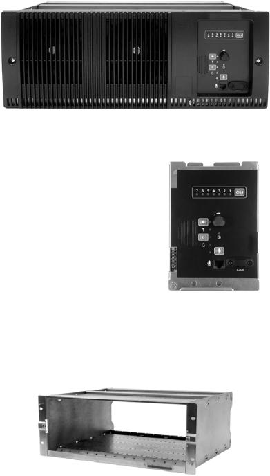
Power Amplifier
The power amplifier amplifies the RF output from the reciter and is available in 5W, 50W and 100W models.
The 5W and 50W models mount vertically in the subrack, while the 100W model mounts horizontally as it has a wider heatsink. The 100W PA is also fitted with an airflow duct.
5/50W PA |
100W PA |
All three models are designed to operate on the 28VDC output provided by the power management unit. In addition, variants of the 5W and 50W models are available for DC-only operation. These two 12V PAs are fitted with an internal boost regulator board, which converts the 12V nominal DC input to a 28VDC output to power the PA circuit boards. The boost regulator board also provides a 12VDC output to power the reciter.
The first 5W or 50W PA is installed in position 3 of the subrack. The second 5W or 50W PA is installed in position 5. The 100W PA occupies positions 3, 4 and 5 and shares a connection with the PMU to position 6 of the subrack. PAs are not required in a gateway or receive-only base station.
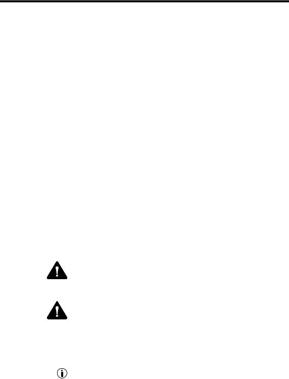
Power Management Unit
The PMU provides the 28VDC power supply for the modules in the subrack. The input voltage can be AC, DC or both AC and DC, depending on the model. The PMU also has an auxiliary DC output of 13.65VDC, 27.3VDC, or 54.6VDC, depending on the model.
The PMU can only be installed in positions 6 and 7 of the subrack. It is connected to position 6.
AC and DC PMU shown
TB9100/P25 CG/P25 TAG Installation and Operation Manual |
Description |
15 |
© Tait Limited March 2014 |
|
|
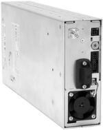
Front Panel
The front panel is mounted onto the subrack with two quick-release fasteners. It incorporates the cooling fans for the PAs and the PMU if these modules are present.
Control Panel
The control panel is mounted onto the subrack and is accessible through an opening in the front panel. The control panel provides some manual control of the channels in the subrack, can display status information for each channel and allows the technician to make and receive calls (refer to “Control Panel” on page 79).
It is a technician tool rather than a user facility.
Subrack
The 4U subrack is made of passivated steel and is designed to fit into a standard 19 inch rack or cabinet.
It is fitted with a configurable subrack interconnect board that provides switching and control logic. The position of a module in the rack is defined by the socket in the subrack interconnect board to which the module is connected by the system control bus.
16 |
Description |
TB9100/P25 CG/P25 TAG Installation and Operation Manual |
|
|
© Tait Limited March 2014 |
1.4Frequency Bands and Sub-bands
Much of the circuitry in the base station is common to both frequency bands, and is therefore covered by a single description in this manual. Where the circuitry differs between VHF and UHF, separate descriptions are provided for each frequency band. In some cases the descriptions refer to specific VHF or UHF bands or sub-bands, and these are identified with the letters listed in the following table.
|
Frequency |
Frequency Band and Sub-band |
|
|
Identification |
||
|
|
|
|
|
|
|
|
VHF |
B band |
B1 = 136MHz to 174MHz |
|
|
B2 = 136MHz to 156MHz |
||
|
B3 = 148MHz to 174MHz |
||
|
|
||
|
|
|
|
|
H band |
H0 |
= 380MHz to 520MHza |
|
|
H1 |
= 400MHz to 440MHz |
|
|
H2 |
= 440MHz to 480MHz |
UHF |
|
H3 |
= 470MHz to 520MHz |
|
H4 |
= 380MHz to 420MHz |
|
|
|
|
|
|
|
|
|
|
K band |
K4 = 762MHz to 870MHzb |
|
|
|
|
|
|
L band |
L1 = 852MHz to 854MHz and 928MHz to 930MHzc |
|
|
|
|
|
a.Only PAs with hardware version 00.02 and later can operate from 380MHz to 520MHz. PAs with hardware version 00.01 and earlier can only operate from 400MHz to 520MHz.
b.The actual frequency coverage in this band is:
Transmit: 762MHz to 776MHz, and 850MHz to 870MHz Receive: 792MHz to 824MHz
c.Only 5W L-band base stations are available. They currently only have compliance for sale in Australia, and are unavailable in other markets.
1.5Product Options
The modular design of the base station means that it is available in many variations. A range of features that can be enabled in software adds another level of configurability. Here are some of the different products that result from different module combinations.
Base Station/Repeater
The standard combination of modules is suitable for use as a line-connected base station and as a repeater. This is the typical base station configuration described in “Theory of Operation” on page 21. Depending on its PMU, it can operate on AC power, DC power, or a combination of both.
TB9100/P25 CG/P25 TAG Installation and Operation Manual |
Description |
17 |
© Tait Limited March 2014 |
|
|
12V DC PA-Only Base Station/Repeater
The base station can be provided without a PMU for those who prefer to use an external third party power supply. The 12V DC input is connected directly to the 12V PA. This is a variant of the PA that includes a boost regulator board. This board converts the 12V nominal DC input to a 28VDC output to power the PA circuit boards. The boost regulator board also provides a 12VDC output to power the reciter. Customers must provide their own power supply. Without a PMU, the base station can only be powered by DC and cannot carry out its power management functions.
Receive-only Base Station
The base station can be provided as a receive-only variant in systems that need sites to enhance the receive coverage. This consists of a single reciter in a subrack, with or without power management. The exciter is present but not licensed to transmit.
Console Gateway
A console gateway consists of a gateway module in a subrack, optionally with a PMU. A subrack can contain several gateway modules. The console gateway’s analog line connects to the dispatch system, and its Ethernet interface connects to the Tait P25 Network. It has no RF functionality.
Encrypted voice quality is indistinguishable from unencrypted.
The console gateway supports Project 25 compliant DES (via the basic encryption license) and AES (Advanced Encryption Standard) with the AES license.
Since the control panel is another analog access point, decryption at the control panel could be a point of insecurity in the system. For this reason, there is no encryption or decryption to the control panel. The control panel speaker plays unencrypted speech (if that is present at the gateway). If the gateway is receiving or transmitting encrypted speech, the speaker simply produces encrypted noise.
Trunked Analog Gateway
A trunked analog gateway consists of a gateway module in a subrack, optionally with a PMU. A subrack can contain several gateway modules. A trunked analog gateway differs from a console gateway only in the software feature licenses it has. The trunked analog gateway’s analog line connects to the dispatch system, and its Ethernet interface connects (via the CSSI protocol) to an RFSS controller in a Tait P25 Trunked Network. It has no RF functionality.
18 |
Description |
TB9100/P25 CG/P25 TAG Installation and Operation Manual |
|
|
© Tait Limited March 2014 |
Encrypted voice quality is indistinguishable from unencrypted.
The trunked analog gateway supports Project 25 compliant DES (via the basic encryption license) and AES (Advanced Encryption Standard) with the AES license.
The control panel in a trunked analog gateway has limited functionality. The Power and Alarm LEDs are operational, but the microphone and speaker are not used.
1.6Applications
TB9100 base stations can be used as repeaters or as base stations. They can be connected together as a channel group, to form a wide area repeater or wide area base station. They can be used in trunking systems and in conventional systems with analog or digital dispatch equipment. For more information, see the appropriate Tait P25 System Manual.
Repeater
The base station can function as a standalone repeater. The analog line is not used and the Ethernet line is only used for CSS access.
Line-Connected Base Station
Analog |
The base station can function as a line-connected base station. Analog |
|
dispatch equipment is connected to the analog line. |
Digital |
The base station can make available a digital fixed station interface (DFSI) |
|
for connecting to digital dispatch equipment. |
Channel Group
Base stations that are interconnected over an IP-based linking infrastructure can be configured as a channel group. Together, they operate as a single logical channel, forming a wide area repeater, wide area base station, wide area trunking control channel or trunking traffic channel.
Trunking Control or Traffic Channel
Base stations can be interfaced to an external trunking site controller. Under instructions from the site controller, they can function as a control channel or a traffic channel.
TB9100/P25 CG/P25 TAG Installation and Operation Manual |
Description |
19 |
© Tait Limited March 2014 |
|
|

Simulcast
Base stations can operate as part of a simulcast channel group. The transmitters in the channel group are synchronized and transmit simultaneously on the same frequency. Each transmitter needs a highly accurate 1PPS pulse and an external frequency reference, so that it can time transmissions with the required accuracy.
P25 Linking
A pair of base stations can function as linking transceivers and be used to provide an RF link, for example between a channel group and a base station at a remote site.
Figure 1.1 Base stations as linking transceivers
Base |
Linking |
Linking |
Base |
station |
transceiver |
transceiver |
station |
|
Channel group |
Channel group |
|
|
communications |
communications |
|
|
Local site |
Remote site |
|
A base station must be appropriately configured using the CSS before it can function as a linking transceiver. As voting information cannot be carried over the RF link, signals that the linking transceiver provides to its channel group must be assigned a source type and given a fixed impairment value. For details, see the appropriate Tait P25 System Manual and the CSS Help or manual.
Data Gateway
The data gateway is a function carried out in a Tait P25 base station or P25 console gateway operating in a TaitNet P25 conventional network. It provides a gateway between P25 radios and a data server. The data gateway interfaces to P25 radios using the P25 common air interface (CAI) and to a data server (such as the KMF) using the IP network. The data gateway function requires the Conventional Packet Data Services feature license and is enabled in configuration. For details, see the TaitNet P25 Conventional Networks System Manual and the CSS Help or manual.
20 |
Description |
TB9100/P25 CG/P25 TAG Installation and Operation Manual |
|
|
© Tait Limited March 2014 |
Console Gateway
The console gateway interfaces a third party analog dispatch console to a Tait P25 Network. It acts as an encryption/decryption point, enabling the analog dispatch console to participate in encrypted calls. A console gateway is a channel group member, connecting the dispatch console to the channel group.
Trunked Analog Gateway
The trunked analog gateway interfaces a third party analog dispatch console to a Tait P25 trunked network. Each trunked analog gateway makes a ‘channel’ available to the dispatcher by providing a connection into the trunked network. The dispatch console can be considered a virtual radio, with the gateway providing the dispatcher with a radio identity on the trunked network. The trunked analog gateway acts as an encryption/ decryption point, enabling the analog dispatch console to participate in encrypted calls.
1.7Theory of Operation
Figure 1.2 Base station high-level diagram
|
RF To |
External Reference |
|
RF From |
|
Antenna |
Frequency (if used) |
|
Antenna |
|
|
|
|
RS-232 + |
|
28VDC |
RF + |
|
Digital I/O |
AC I/P |
|
|
||
(high current) |
PA Key |
|
|
|
PMU |
Reciter |
|
||
PA |
|
Analog Line |
||
DC I/P |
|
|
|
(4-wire E&M) |
|
|
|
|
|
|
28VDC (low current) |
|
|
Ethernet |
|
|
|
|
Interface |
|
System Control Bus |
|
Network |
|
|
|
|
||
|
|
Control |
|
|
|
|
Panel |
|
|
|
|
Speaker |
Microphone |
|
|
|
O/P |
I/P |
|
TB9100/P25 CG/P25 TAG Installation and Operation Manual |
Description |
21 |
© Tait Limited March 2014 |
|
|
The reciter receives RF signals from its RF input and sends RF from its RF output to the PA, along with a PA key signal. The reciter also receives signals from and sends signals to the analog line, the Ethernet interface, and the control panel (see Figure 1.2).
A system control bus interconnects the modules and carries alarm and control signaling between the reciter and the other modules.
The control panel speaker and microphone enable the base station maintainer to communicate with the dispatcher or with subscriber unit radios. The Ethernet interface carries voice over IP as well as communications with the CSS.
The reciter carries out signal processing and has overall control of the base station. It comprises an RF, a digital, and a network board, as shown in Figure 1.3.
Figure 1.3 |
Reciter boards |
|
|
|
|
|
|
|
||||
|
|
|
|
|
|
|
|
|
|
|
|
|
|
RF I/P |
|
|
|
|
|
|
|
Ethernet |
|||
|
|
|
|
|
|
|
|
|||||
|
|
|
|
|
RF |
|
Digital |
|
Network |
|
|
Interface |
|
|
|
|
|
|
|
|
|||||
|
|
|
|
|
|
|
|
|
RS-232 + |
|||
|
RF O/P |
Board |
|
Board |
|
Board |
|
|
Digital I/O |
|||
|
|
|
|
|
|
|
|
|
||||
|
|
|
|
|
|
|
|
|
|
|
|
Analog Line |
|
|
|
|
|
|
|
|
|
|
|
||
|
|
|
|
|
|
|
|
|
|
|
|
|
|
|
|
|
|
|
|
|
|
|
|
|
|
|
|
|
|
|
|
|
|
|
|
|
|
|
|
|
|
|
|
|
|
Control |
|
|
|
|
|
|
|
|
|
|
|
|
Panel |
|
|
|
|
|
|
|
|
|
|
|
|
|
|
|
|
|
|
Maintainer Access
The RF board contains the receiver and exciter circuitry.
The digital board converts information between analog and digital and controls the maintainer’s access via the control panel. It also performs the air interface signal processing for both analog FM and digital P25 modes.
The network board acts as the link between the digital circuitry and the Tait P25 Network, and gives the base station an identity as a network element. It also provides the physical connections for the Ethernet, analog and RS-232 serial interfaces.
For more detailed information, see “Technical Description” on page 117.
22 |
Description |
TB9100/P25 CG/P25 TAG Installation and Operation Manual |
|
|
© Tait Limited March 2014 |

Signal Paths
Figure 1.4 gives an overview of signal paths within the reciter.
Figure 1.4 Reciter signal paths
Digital Board
InterfaceRF |
|
|
|
|
|
Modulator/ demodulator |
|
|
|
P25 |
|
|
|
|
|
|
|
|
|||
|
|
|
|
|
|
|
|
process |
||
|
|
|
|
|
|
|
|
|
|
modem |
|
|
ADC |
|
|
|
|
|
|
|
FM audio |
|
|
|
|
|
|
|
||||
|
|
|
|
|
|
|
|
|
|
|
|
|
|
|
|
|
|
|
|
|
|
|
Network board |
|
|
|
|
Protocol |
|
|
Main |
stack |
Ethernet |
|
RTP |
||
|
|
||
|
switch |
|
|
|
UDP |
|
|
|
|
|
|
|
|
IP |
Interface |
G.711 |
|
|
|
|
|
|
|
G.711 |
DSP |
G.711 |
|
|
|
|
|
Vocoder |
switch |
Vocoder |
|
|
|
||
ADC |
|
ADC |
Control panel Analog line
1.Incoming signals all go to the main switch.
a.Digital P25 signals from the RF interface go straight from the digital board to the main switch.
b.Analog FM signals from the RF interface go from the FM audio processing circuitry via a G.711 encoder to the DSP switch, which routes them to the main switch.
c.All signals from the channel group go through the protocol stack straight to the main switch.
d.Signals from the control panel microphone or from the analog line pass first through an ADC, which converts them from analog to a 128kbit/s digital stream. Then, if they are analog FM, they pass through a G.711 encoder. If they are digital P25, they pass through an IMBE vocoder. The DSP switch then routes them to the main switch.
2.The main switch handles the signals according to the reciter’s configuration and role within the channel group. It may vote between RF-originated signals. If there are multiple signals, it selects or prioritizes them.
3.The main switch routes the signals to the appropriate destinations:
■ RF interface (via the digital board), for transmitting P25 over the air)
■ Ethernet interface (via the IP protocol stack), for sending to the
TB9100/P25 CG/P25 TAG Installation and Operation Manual |
Description |
23 |
© Tait Limited March 2014 |
|
|
other channel group members
■ DSP switch, for further routing and for converting back to analog
4.The DSP switch coordinates the DSP processing of the signals and routes them to the RF interface, analog line and/or the control panel speaker).
5.Each destination interface makes available the signal with the highest priority for that interface.
Run and Standby Modes
The base station normally operates in Run mode, but you can use the CSS to put it in Standby mode.
Run mode |
In Run mode, the base station performs its normal functions. |
Standby mode |
When you program the base station or run invasive diagnostic tests, the base |
|
station must be in Standby mode. This takes the base station out of service. |
|
However, the control panel is still effective; you can use it to send and |
|
receive over the air and across the analog line and to receive from the channel |
|
group interface. |
Dual Mode
|
The base station can handle analog FM calls as well as digital P25 calls. It is |
|
a dual-mode base station. However, it can be configured to always operate |
|
in one mode. For example, if only digital P25 radios use the base station, the |
|
base station can ignore analog FM calls. Note that at any one time, the base |
|
station can only handle one call, either analog FM or digital P25. It cannot |
|
receive a call in one mode and repeat it in the other. |
Analog FM mode |
In Analog FM mode, the base station can receive and transmit over the RF |
|
interface using analog FM modulation. Analog FM speech is sent and |
|
received over the channel group interface using the G.711 format. |
Digital P25 mode |
In digital P25 mode, the base station can receive and transmit over the RF |
|
interface using digital P25 modulation. Digital speech is in the IMBE |
|
(Improved Multi-Band Excitation) format. |
Dual mode |
Dual mode is configured not for the base station as a whole, but for the |
configuration |
inputs at a particular interface. The mode of outputs is not configurable; it |
|
can always be either analog FM or digital P25, depending on the input. |
|
When the base station receives an input on an interface, it operates in the |
|
mode of that input. |
24 |
Description |
TB9100/P25 CG/P25 TAG Installation and Operation Manual |
|
|
© Tait Limited March 2014 |
Dual mode is configured or selected at the different inputs in the following way:
Input interface |
Description |
|
|
RF |
The RF interface can be configured in channel profiles |
|
to receive analog FM speech, digital P25 speech or |
|
both (dual mode). In dual mode, the receiver listens |
|
for digital P25 signals. If they are detected, the base |
|
station operates in digital P25 mode, otherwise in |
|
analog FM mode. |
|
|
Analog Line |
The analog line receives analog speech signals from |
|
the dispatch console. The current calling profile |
|
defines whether the signal is to be handled as digital |
|
P25 or analog FM. Different calling profiles can select |
|
different modes. |
|
|
Digital fixed station interface |
The DFSI receives speech signals whose mode has |
|
already been defined by the FSH. The FSI is always |
|
capable of receiving calls in either mode. |
|
|
Channel group interface |
The channel group interface receives speech signals |
|
whose mode has already been defined by the |
|
channel group member that is the source of the call. |
|
The channel group interface is always capable of |
|
receiving calls in either mode. |
|
|
Control Panel |
The control panel receives speech from the |
|
connected microphone. The user selects digital P25 |
|
or analog FM mode using the microphone button. |
|
Refer to “Microphone Operation” on page 82 for |
|
further details. The destination of the signal is |
|
configured by the CSS. |
|
|
TB9100/P25 CG/P25 TAG Installation and Operation Manual |
Description |
25 |
© Tait Limited March 2014 |
|
|

Intermodule Communications
A system control bus and a subrack interconnect board interconnect the modules in the subrack and carry alarm and control signaling between the reciter and the other modules, as shown in Figure 1.5.
Figure 1.5 Intermodule communication paths
|
|
|
Reciter |
|
PA |
|
PMU |
|
|
|
μP |
|
μP |
μP |
I2C Current |
|
|
|
|
|
|
|
Source |
|
|
C |
Speaker |
Mic |
Fan |
I2C |
Fan |
|
|
2 |
|
|
|
||
|
|
I |
|
|
|
||
Control Panel |
|
|
|
|
|
|
|
Microphone |
|
|
|
|
|
|
|
|
Speaker |
|
|
|
|
|
|
|
User |
I2C |
|
|
|
|
|
|
|
|
|
|
|
|
|
|
Controls |
|
|
|
|
|
|
|
|
|
|
|
Subrack Interconnect Board |
||
PA |
PMU |
|
|
|
|
|
|
Fan |
Fan |
|
|
|
|
|
|
26 |
Description |
TB9100/P25 CG/P25 TAG Installation and Operation Manual |
|
|
© Tait Limited March 2014 |
Power Management
AC to DC Changeover
Base stations with a PMU manage the supply of power to ensure uninterrupted operation of the base station. A range of parameters is monitored and can trigger alarms that are sent via the reciter to the CSS and a syslog collector.
When the PMU has an AC and a DC module, the base station can be powered by either the AC (mains) or the DC (battery) supply. The base station will default to the AC supply if both supplies are provided. If the AC supply becomes unavailable, a seamless changeover from the AC to DC supply takes place, providing that the battery voltage is above the configured minimum. You can use the CSS to monitor whether the base station is running on battery or mains power.
DC Operation |
When the base station is running off the DC supply and the battery voltage |
|
falls below the configured minimum, the base station will enter PMU |
|
Shutdown mode to protect the battery and base station equipment. The |
|
standby power supply card maintains the power to the PMU microprocessor, |
|
while the rest of the PMU is shut down. When the battery voltage rises to |
|
the configured startup setting, power is resumed to the DC supply. Refer to |
|
“PMU Operation on DC Input” on page 129 for more detailed |
|
information. |
Auxiliary Power |
The output from the auxiliary power supply board can be used to power |
Control |
other site equipment. The maximum output is 40W. |
Power Distribution
Subracks with a PMU
Figure 1.6 shows how power is distributed to modules in the subrack. One method is used if there is a PMU, another if there is a 12V PA and yet another if there is neither PMU nor PA.
The subrack can receive input power from either the AC or DC input. The PMU provides a 28V output to the PA and to the reciters. Internal seamless switching between the AC or DC input ensures there are no power interruptions should a changeover occur between the two inputs. The base station will default to the AC input if both AC and DC inputs are provided.
The AC converter has a series switch which isolates the mains input from the converter. The DC input, however, has much higher current ratings, and supports an on/off switch on the converter only.
The outputs from both the AC and DC high power converters are added together and fed to the PA via the PA1 and PA2 outputs. The auxiliary output is also tapped off this summed output.
TB9100/P25 CG/P25 TAG Installation and Operation Manual |
Description |
27 |
© Tait Limited March 2014 |
|
|

12V DC PA-only subracks
In 12V DC PA-only base stations, the DC power input is connected directly to the PA, where it is fed to the internal boost regulator board. This board provides a 12VDC output for the reciter and a 28VDC output for the PA circuit boards.
Subracks with no PA and no PMU
Distribution from the reciter
When the subrack has neither PMU or PA, reciters or gateway modules obtain their power from a DC terminal block at the rear of the subrack.
The reciter input power feed is distributed to all internal reciter boards. Local regulation ensures that noise and common mode interface signals are kept to a minimum between sub-assemblies. Various power supplies in the reciter further power and isolate critical sub-sections.
The reciter also powers the control panel, via a backpower protection diode. The system control bus is used to route power from the reciter to the control panel. When a reciter is powered and plugged into the control bus, if a control panel is connected there will always be a reciter present to drive the control bus functions.
Figure 1.6 |
Subrack power distribution |
|
|
|
|
|
|
|
|
|
|
|
|
|
|
|
|||||||||||
|
|
|
|
|
|
|
|
|
|
|
|
|
|
|
|
|
|
|
|
|
|
|
|
|
|
|
|
|
|
|
Subrack with PMU |
|
|
12 V DC |
Subrack with no |
||||||||||||||||||||
|
|
|
PA-only subrack |
PA and no PMU |
|||||||||||||||||||||||
|
|
|
|
DC |
AC |
|
|
|
|
|
|
|
|
|
12V |
10.8 - 32V |
|||||||||||
|
|
|
|
|
|
|
|
|
|
|
|
|
|
|
|
|
|
|
|
|
|
|
|
|
|
DC terminal at |
|
|
|
|
|
|
|
|
|
|
|
|
|
|
|
|
|
|
|
|
|
|
|
|
|
|
|
||
|
|
|
|
|
|
|
|
|
|
|
|
|
|
|
|
|
|
|
|
|
|
|
|
|
|
||
|
|
|
|
|
|
|
|
|
|
|
|
|
|
|
|
|
|
|
|
|
|
|
|
|
|
||
|
|
|
|
|
|
|
|
|
|
|
|
|
|
|
|
|
|
|
|
|
|
|
|
|
|
rear of subrack |
|
|
|
|
|
|
|
|
|
|
|
|
|
|
|
|
PA |
|
|
|
|
|
|
|
|
|
|||
|
|
|
|
|
PMU |
|
|
|
Aux. DC |
|
|
Boost |
|
|
|
|
|
|
|
|
|
|
|
||||
|
|
|
|
|
|
|
|
|
|
Regulator |
|
|
|
|
|
|
|
|
|
|
|
||||||
|
|
|
|
|
|
|
|
|
|
|
|
|
|
|
|
|
|
|
|
|
|
|
|
||||
|
|
|
|
|
|
|
|
|
|
|
|
|
|
|
|
28V |
|
|
|
|
|
|
|
J17 connector |
|||
|
|
|
|
|
|
|
|
|
|
|
|
|
|
|
|
|
|
|
|
|
|
|
|
|
|
on subrack inter- |
|
|
|
|
28V |
|
|
28V |
|
|
|
|
|
|
|
|
|
|
|
|
|
|
|
|
|
connect board |
|||
|
|
|
|
|
|
|
|
|
|
|
|
|
|
|
|
|
|
|
|
|
|
|
|
||||
|
|
|
|
|
|
|
|
|
|
|
|
|
|
|
|
|
|
|
12V |
|
|
|
|
|
|
|
|
|
|
|
|
|
|
|
|
|
|
|
|
|
|
|
|
|
|
|
|
|
|||||||
|
|
|
|
|
|
|
|
|
|
|
|
|
|
|
|
|
|
|
|
|
|
|
|
|
|
|
|
|
|
|
|
|
|
|
|
|
|
|
|
|
|
|
|
|
|
|
|
|
|
|
|
|
|
|
|
|
|
PA |
|
|
|
|
|
Reciter |
|
|
|
Reciter |
|
|
|
Reciter |
|
||||||||||
|
|
|
|
|
|
|
|
|
|
|
|
|
|
|
|
|
|
|
|
|
|
|
|
|
|
|
|
|
|
|
|
|
|
|
|
|
|
|
28V |
|
|
|
12V |
|
|
|
|
10.8 |
|
||||||
|
|
|
|
|
|
|
|
|
|
|
|
|
|
|
|
|
|
|
|
|
|
|
|
|
|
- 32V |
|
|
|
|
|
|
|
|
|
|
|
|
|
|
|
|
|
|
|
|
|
|
|
|
|
|
|
|
|
|
|
|
|
|
|
|
|
|
|
|
|
|
|
|
|
|
|
|
|
|
|
|
|
|
|
|
|
|
|
|
|
|
|
|
|
|
Control |
|
|
|
Control |
|
|
|
Control |
|
|||||||||
|
|
|
|
|
|
|
|
|
Panel |
|
|
|
Panel |
|
|
|
Panel |
|
|||||||||
|
|
|
|
|
|
|
|
|
|
|
|
|
|
|
|
|
|
|
|
|
|
|
|
|
|
|
|
|
|
|
|
|
|
|
|
|
|
|
|
|
|
|
|
|
|
|
|
|
|
|
|
|
|
|
|
28 |
Description |
TB9100/P25 CG/P25 TAG Installation and Operation Manual |
|
|
© Tait Limited March 2014 |
Front Panel Fans
Configuring Fan
Control
The front panel can be equipped with up to two fans. One fan is for the PMU and the other is for the PAs. (Reciters also have fans, see “Reciter Fan Operation” on page 121.)
Front panel fans do not operate continuously but are switched on and off as needed by the reciter firmware.
When the base station powers up, the fans turn on: the PMU fan runs first, followed by the PA fan (the reciter fans will also power up, after the PA fan). Each fan will run for about 5 seconds before switching off.
Front panel fans must have the correct wiring: power and ground (2-wire fans), or power, ground, and rotation detect (3-wire fans). Both fans in a subrack must be of the same type. If 3-wire fans are fitted, the reciter can monitor whether the fans are rotating and generate an alarm if the fan fails.
The control and monitoring of the fans is performed by the reciter selected at the control panel. We recommend that you enable the fan alarms for reciter 1 and disable the fan alarms for the other reciters.
The operation of the PA fan is configurable via the CSS; you can specify the threshold temperature at which the fan will be turned on, and set the fan to operate only when the PA is transmitting.
The PMU fan has fixed on/off thresholds and a defined set of duty cycles based on the PMU temperature and load current, as described in the following table.
PMU Temperature |
Current |
Fan Duty Cycle |
|
|
|
|
|
<149°F (65°C) |
<4A |
always off |
|
|
4A |
–6A |
2 minutes on, 8 minutes off |
|
6A |
–8A |
2 minutes on, 5 minutes off |
|
8A |
–12A |
3 minutes on, 3 minutes off |
|
12A–14A |
4 minutes on, 1 minute off |
|
|
≥15A |
always on |
|
|
|
|
|
>149°F (65°C) |
–– |
|
always on |
|
|
|
|
TB9100/P25 CG/P25 TAG Installation and Operation Manual |
Description |
29 |
© Tait Limited March 2014 |
|
|
30 |
Description |
TB9100/P25 CG/P25 TAG Installation and Operation Manual |
|
|
© Tait Limited March 2014 |
 Loading...