


OPERATOR’S MANUAL
AUTOMATED HEMATOLOGY ANALYZER
KX-21
CHAPTER 1: |
INTRODUCTION |
CHAPTER 2: |
SAMPLE ANALYSIS |
CHAPTER 3: |
DISPLAY AND PROCESSING OF ANALYSIS RESULTS |
CHAPTER 4: MAINTENANCE AND SUPPLIES REPLACEMENT |
|
CHAPTER 5: |
QUALITY CONTROL |
CHAPTER 6: |
CALIBRATION |
CHAPTER 7: |
TROUBLESHOOTING |
CHAPTER 8: |
ADJUSTMENT |
CHAPTER 9: |
FUNCTIONAL DESCRIPTION |
CHAPTER 10: INSTRUMENT SETUP |
|
APPENDIX A: |
INSTALLATION |
APPENDIX B: TECHNICAL INFORMATION
INDEX
SYSMEX CORPORATION
KOBE, JAPAN
Copyright 1997 - 2000 by SYSMEX CORPORATION |
|
All rights reserved. No part of this Operator’s Manual may be |
Code No. 461-2261-1 |
reproduced in any form or by any means whatsoever without |
PRINTED IN JAPAN |
prior written permission of SYSMEX CORPORATION. |
Date of Last Revision: January 2000 |

•Sysmex is a registered trademark of SYSMEX CORPORATION.
•CELLCLEAN, CELLPACK, EIGHTCHECK-3WP, STROMATOLYSER-WH are trademarks of SYSMEX CORPORATION.
•Cubitainer is a registered trademark of Hedwin Corporation.
•Teflon is a registered trademark of E.I. du Pont de Nemours & Co., Inc.
•VENOJECT is a registered trademark of Terumo Corporation.
•Other trademarks referenced are property of their respective owners.
•It is prohibited to reproduce part or all of the contents of this Manual without permission.
•The display screens carried in this Manual may in some cases differ from actual screens.
•We reserve the right to make further improvements and incorporate them in our products, which then will have some points that differ from descriptions in this Manual.
•Patient names and doctor names are entered for information and illustration purposes only, and do not imply real specific persons.
Sysmex KX-21 Operator’s Manual -- Revised October 1998
RECEIVING INSTRUCTIONS
The KX-21 has been thoroughly tested before shipment, and has been packaged carefully to prevent damage from shipping and handling. Reagents and options have also been sent and will arrive at approximately the same time as the analyzer. Follow these guidelines when the system arrives:
•Check to see that the arrows on the sides of the packages are pointing up. If the arrows do not point up, remark this information on the bill of lading.
•Visually inspect the outside of the package for rips, dents, or possible shipping damage. Document any sign of damage on the bill of lading, regardless of how insignificant it may appear. This is for your protection!
•Notify your service representative that the KX-21 system and its components have arrived.
•Wait for your service representative to unpack the system and open the packages.
•Follow the unpacking and storage instructions provided on the outside of the package. Special requirements such as refrigeration are clearly marked on the outside of the carton and will be included in the unpacking instructions and package inserts.
WARRANTY INFORMATION
All instruments manufactured by Sysmex® are warranted against defective materials or workmanship for a period of one year commencing on the installation date at the customer's required location.
This Warranty does not cover any defect, malfunction, or damage due to:
1. Accident, neglect or willful mistreatment of the product
2. Failure to use, operate, service, or maintain the product in accordance with the applicable Sysmex Operator's Manual
3. Failure to use the appropriate reagents or chemicals specified for the product
Sysmex KX-21 Operator’s Manual -- Revised October 1998 |
I |
ENSURE SAFE OPERATION OF THE INSTRUMENT
Before operating this instrument, carefully read the "Ensure Safe Operation of the Instrument" and OPERATOR’S MANUAL, and strictly follow the instructions given in them.
This manual carries a variety of illustrations to make sure that the product can be used safely and correctly, thus preventing you and others from suffering injuries and damage to property.
The illustrations and meaning are described in the following.
Do understand what they mean before proceeding to the text of the MANUAL.
Meaning of Signs
WARNING • If this sign is ignored and the instrument is operated incorrectly, there is a potentially hazardous situation which could result in death or serious
injury of an operator, or grave property damage.
• If this sign is ignored and the instrument is operated incorrectly, there is CAUTION a potentially hazardous situation which may result in injury of an
operator, adverse effect on output results, or will cause property damage.
Caution on Diagnosis
• This product is a clinical instrument for screening of abnormalities. CAUTION Clinical judgments by physicians should take into account results from
clinical examinations and other test results besides hematology result.
II |
Sysmex KX-21 Operator’s Manual -- Revised October 1998 |

 WARNING
•In the event the instrument emits abnormal odor or any smoke, turn off the power immediately and disconnect the power plug from the wall socket.
If the instrument is used continuously in that state, there is a hazard that fire, electrical shock, or injury may result.
Contact your Sysmex service representative for inspection.
•Take care not to spill blood or reagent, or drop wire staples or paper clips into the instrument.
Those might cause short circuit or smoke emission. If such trouble should occur, turn off the power supply immediately and pull off the power plug from the wall socket. Then contact Sysmex service representative for inspection.
•Do not touch the electrical circuits inside the cover. Especially if your hands are wet, there is a hazard that electrical shock may result.
•Always wear rubber gloves when performing maintenance work or inspection. Use specified tools and parts.
After work is over, wash your hands with disinfectant.
There is a possibility that those areas of the hand which came in contact with blood could suffer infection, electrical shock, or burn.
•Be careful when handling samples.
Always wear rubber gloves; otherwise infection by bacteria could result. If bacteria happen to enter your eye or a cut, wash it off with plenty of water, and immediately see a doctor.
•When discarding waste liquid, or disassembling/assembling the related parts, do not touch the waste liquid.
If it is contaminated with blood, infection of bacteria may result. If you should touch the waste liquid inadvertently, wash it off with disinfectant first, then wash it off with soap.
When Handling Reagent
•If a reagent happens to enter your eye, wash it off immediately using plenty of water, and take medical treatment at once.
•If you should swallow it inadvertently, call for a doctor immediately, drink plenty of water, and throw up.
•If it happens to adhere to the hand or the skin of other area, wash it off using plenty of water.
•When discarding waste liquid and instrument consumable, take proper disposing steps as medical, ineffective, and industrial wastes.
If they are contaminated with blood, infection of bacteria may result.
•Do not modify the instrument. (Modification is prohibited by Pharmaceutical Affairs Law in Japan.) Check the regulations that apply to laboratories in your country.
Sysmex KX-21 Operator’s Manual -- Revised October 1998 |
III |

 WARNING
Power Supply, Connection, and Grounding
•Never put the power plug in any socket other than the specified voltage.
Otherwise, fire or electrical shock will result.
•When installing the instrument, be sure to ground it.
Otherwise, fire or electrical shock will result.
Handling Power Supply Cord
•Take care not to damage the power cord, place a heavy device on it, or pull it forcibly.
Otherwise, the wire may break causing fire or electrical shock.
•When connecting the instrument to a peripheral (host computer), be sure to switch off the power supply beforehand.
Otherwise, electrical shock or instrument failure may result.
I V |
Sysmex KX-21 Operator’s Manual -- Revised October 1998 |

 CAUTION
Use of Reagents
•After unpacking, be sure not to allow dust, dirt, or bacteria to come in touch with the reagent.
•Do not use reagents which are out of the expiration date.
• Handle a reagent gently to prevent formation of bubbles.
•Take care not to spill a reagent. If it spills, wipe it off immediately using a wet cloth or the like.
•Follow other instructions described on the Package Insert on each reagent.
Use of Instrument
•When performing maintenance work or inspection, use specified tools and parts. Do not use substitute parts, or modify the instrument. It is hazardous.
•Do not bring your body or clothes close to the instrument.
•Those who have no or only limited experience in using reagents are recommended to have guidance or assistance of those with sufficient experience .
•If the instrument has developed a trouble by any chance, a person in charge of it should take steps within the range specified in the OPERATOR’S MANUAL. As to troubles other than mentioned in it, contact Sysmex service representative for repair.
•Unpacking, installation, and confirmation of initial operation must be done by Sysmex service representative.
Environment for Use
•Install the instrument in a place which is not subject to water splash.
•Install the instrument in a place which is not subject to adverse effects of high
temperature, high humidity, dust, direct sunlight, etc.
•Do not give the instrument a strong vibration or impact.
•Do not install the instrument near a chemical storage or a place where a gas is generated .
Sysmex KX-21 Operator’s Manual -- Revised October 1998 Sysmex KX-21 Operator’s Manual -- Revised January 2000
V
STRUCTURE OF THIS MANUAL
Read this manual carefully so you will be able to use the instrument to its full extent, and operate it correctly. This manual contains ten Chapters and APPENDICES as listed in the following:
Chapter 1: |
Introduction |
Describes overview of this instrument, including the |
||
|
|
outline of the instrument, operation procedure, and |
||
|
|
messages, and cautions during installation. |
||
Chapter 2: |
Sample Analysis |
Describes procedures for start-up of the instrument, |
||
|
|
measurement of the sample, and shut-down. |
||
|
|
Summarizes the operation method for analyzing the |
||
|
|
sample. |
||
Chapter 3: |
Display and Processing of |
Describes the displayed content of the analysis data, |
||
|
Analysis Results |
and the process of the latest sample/stored data. |
||
|
Also describes the manual analysis and the external |
|||
|
|
|||
|
|
output. |
||
Chapter 4: |
Maintenance and Supplies |
Describes scheduled maintenance and replacement |
||
|
Replacement |
method of supplies such as reagent. |
||
|
|
|
|
|
Chapter 5: |
Quality Control |
Describes execution procedures of the |
|
control and L- |
X |
||||
|
|
J control for quality control. |
||
Chapter 6: |
Calibration |
Describes procedures for automatic/manual calibration. |
||
Chapter 7: |
Troubleshooting |
Describes error messages and troubleshooting. |
||
|
|
|
||
Chapter 8: |
Adjustment |
Describes the method of pressure adjustment based on |
||
|
|
the troubleshooting. |
||
Chapter 9: |
Functional Description |
Describes the analyzing principles of this instrument |
||
|
|
and names of the components. |
||
Chapter 10: |
Instrument Setup |
Describes the system environment setting such as |
||
|
|
date, time, and unit, and the data analysis setting such |
||
|
|
as data error judgment. |
||
Appendix A: |
Installation |
Describes the installation method of the KX-21. |
||
|
|
|
||
Appendix B: |
Technical Information |
Technical reference data describing the specification for |
||
|
|
host output format. |
||
|
|
(The host output function is an option.) |
||
V I |
Sysmex KX-21 Operator’s Manual -- Revised October 1998 |
INTRODUCTION
Thank you for purchasing the Sysmex® Automated Hematology Analyzer KX-21. Carefully read the OPERATOR'S MANUAL for correct use of the unit.
Keep this MANUAL handy after reading. It will continue to be of your service in finding specific information about this instrument.
Sysmex KX-21 Operator’s Manual -- Revised October 1998 |
VII |
PREMISES FOR SIGNS
Meaning of Signs
WARNING • If this sign is ignored and the instrument is operated incorrectly, there is a potentially hazardous situation which could result in death or serious
injury of an operator, or grave property damage.
CAUTION • If this sign is ignored and the instrument is operated incorrectly, there is a potentially hazardous situation which may result in injury of an
operator, adverse effect on output results, or will cause property damage.
CAUTION: • Indicates what we would like you to know to maintain instrument performance and prevent its damage.
NOTE: • Indicates information which will come handy in operating the instrument.
Document Conventions
In explaining operation, this manual uses the conventions as shown below.
•The keys on the panel keyboard are expressed within square brackets. For example: [SELECT], [ENTER], [ ]
]
•The display on LCD appears within quotation marks. For example: "Stand-by," "WB"
•The name of menu appears within quotation marks. For example: "2: Quality Control," "6: Settings"
NOTE: • LCD and printing described in this manual may differ from that in practice.
•Due to the improvement of the product, the content of this manual may not conform with the product.
VIII |
Sysmex KX-21 Operator’s Manual -- Revised October 1998 |
KX-21 OPERATOR’S MANUAL
TABLE OF CONTENTS
CHAPTER 1: INTRODUCTION
1. |
INTRODUCTION................................................................. |
1-1 |
|
2. |
OVERVIEW OF INSTRUMENT............................................... |
1-2 |
|
3. |
OPTION UNITS ................................................................... |
1-3 |
|
4. |
OUTLINE OF OPERATION .................................................... |
1-3 |
|
5. |
AUTOMATIC STOP FUNCTION OF PNEUMATIC UNIT............... |
1-3 |
|
6. |
ANALYSIS PARAMETERS .................................................... |
1-4 |
|
7. |
PANEL KEYBOARD ............................................................ |
1-6 |
|
8. |
GRAPHIC SCREEN .............................................................. |
1-7 |
|
|
8.1 |
Contents of Display ........................................................ |
1-7 |
|
8.2 |
Status Display Messages................................................... |
1-8 |
|
8.3 |
LCD Brightness Adjustment ............................................. |
1-11 |
9. |
EMERGENCY STOP PROCEDURE ......................................... |
1-11 |
|
10. |
ALARM SOUNDS ............................................................... |
1-11 |
|
11. |
CONTENTS OF PACKAGE ................................................... |
1-11 |
|
12. |
INSTALLATION ENVIRONMENT .......................................... |
1-12 |
|
|
12.1 |
Installation and Relocation ............................................... |
1-12 |
|
12.2 |
Grounding .................................................................. |
1-12 |
|
12.3 |
Installation Space .......................................................... |
1-13 |
|
12.4 |
Installation Environment ................................................. |
1-14 |
13. |
INSTRUMENT SPECIFICATIONS .......................................... |
1-15 |
|
14. |
MENU TREE ..................................................................... |
1-18 |
|
CHAPTER 2: SAMPLE ANALYSIS
1. |
INTRODUCTION................................................................. |
2-1 |
|
|
1.1 |
Overview of Analysis Modes ............................................. |
2-1 |
|
1.2 |
Analysis Procedure Flow Chart........................................... |
2-2 |
2. |
START-UP PROCEDURE....................................................... |
2-3 |
|
|
2.2 |
Inspection before Turning ON the Power ............................... |
2-3 |
|
2.2 |
Turning ON the Power and Self-Check ................................. |
2-5 |
3. |
QUALITY CONTROL ........................................................... |
2-8 |
|
4. |
PROCEDURES IN EACH ANALYSIS MODE .............................. |
2-9 |
|
|
4.1 |
Whole Blood (WB) Mode ................................................ |
2-9 |
|
4.2 |
Pre-Diluted (PD) Mode ................................................... |
2-16 |
5. |
DISPLAY AND PRINTING OF ANALYSIS RESULT ................... |
2-24 |
|
|
5.1 |
Display of Analysis Result ............................................... |
2-24 |
|
5.2 |
Printing of Analysis Result ............................................... |
2-25 |
6. |
LIMITATIONS ................................................................... |
2-26 |
|
|
6.1 |
Cell Count Parameters .................................................... |
2-26 |
|
6.2 |
Limitation of Hemoglobin................................................ |
2-27 |
7. |
EXPECTED RESULTS ......................................................... |
2-28 |
|
8. |
STOPPING THE PNEUMATIC UNIT ....................................... |
2-29 |
|
9. |
EXECUTION OF SHUTDOWN............................................... |
2-30 |
|
|
9.1 |
Shutdown Procedure ...................................................... |
2-30 |
Sysmex KX-21 Operator’s Manual -- Revised January 2000 |
i |

CHAPTER 3: DISPLAY AND PROCESSING OFANALYSIS RESULTS
1. |
INTRODUCTION................................................................. |
3-1 |
|
2. |
PROCESSING LATEST SAMPLES ........................................... |
3-2 |
|
|
2.1 |
Display of Analysis Result ................................................ |
3-2 |
|
2.2 |
Manual Discrimination .................................................... |
3-6 |
|
2.3 |
Printing..................................................................... |
3-10 |
|
2.4 |
Print Paper Feed .......................................................... |
3-10 |
3. |
PROCESSING STORED DATA.............................................. |
3-11 |
|
|
3.1 |
Executing and Quitting Stored Data Processing Program........... |
3-11 |
|
3.2 |
Stored Data Screen ....................................................... |
3-12 |
|
3.3 |
Deletion .................................................................... |
3-15 |
|
3.4 |
Printing..................................................................... |
3-16 |
|
3.5 |
HC Output (Option) ...................................................... |
3-16 |
|
3.6 |
Correcting a Sample Number ........................................... |
3-17 |
CHAPTER 4: MAINTENANCE AND SUPPLIES REPLACEMENT
1. |
INTRODUCTION................................................................. |
4-1 |
|
2. |
KX-21 MAINTENANCE CHECKLIST ....................................... |
4-2 |
|
3 |
DAILY MAINTENANCE AND PROCEDURE ............................. |
4-4 |
|
|
3.1 |
Clean TD Chamber and Diluted Sample Line (Shutdown) ........... |
4-4 |
|
3.2 |
Check Trap Chamber Level and Discard ................................ |
4-6 |
4. |
WEEKLY MAINTENANCE AND PROCEDURE .......................... |
4-7 |
|
|
4.1 |
Clean SRV Tray ............................................................ |
4-7 |
5. |
MONTHLY MAINTENANCE AND PROCEDURE ........................ |
4-9 |
|
|
5.1 |
Clean Waste Chamber (Rinse Sequence)................................ |
4-9 |
|
5.2 |
Clean Transducer (Rinse Sequence) .................................... |
4-12 |
6. |
EVERY 3-MONTH MAINTENANCE AND PROCEDURE............. |
4-16 |
|
|
6.1 |
Clean Sample Rotor Valve (SRV)....................................... |
4-16 |
|
6.2 |
Reset SRV Cycle Counter ............................................... |
4-22 |
7. |
AS-NEEDED MAINTENANCE AND PROCEDURE .................... |
4-24 |
|
|
7.1 |
Auto Rinse .................................................................. |
4-24 |
|
7.2 |
Clean Rinse Cup ........................................................... |
4-26 |
|
7.3 |
Clean WBC/RBC Transducer Aperture ................................ |
4-28 |
|
7.4 |
Replace Waste Tank....................................................... |
4-32 |
8. |
SUPPLIES REPLACEMENT ................................................. |
4-33 |
|
|
8.1 |
Replenish Reagent ......................................................... |
4-33 |
|
8.2 |
Replace Fuse ............................................................... |
4-36 |
|
8.3 |
Replace Printer Paper ..................................................... |
4-37 |
|
8.4 |
Supplies List................................................................ |
4-40 |
9. |
CONFIRMATION OF CYCLE NUMBER.................................. |
4-41 |
|
|
9.1 |
Operation Procedure ..................................................... |
4-41 |
ii |
Sysmex KX-21 Operator’s Manual -- Revised January 2000 |

CHAPTER 5: QUALITY CONTROL
1. |
INTRODUCTION................................................................. |
5-1 |
|||||
|
1.1 |
|
|
Control |
5-1 |
||
|
|
X |
|||||
|
1.2 |
Levy-Jennings Control (L-J) .............................................. |
5-1 |
||||
|
1.3 |
QC Chart Screen ............................................................ |
5-2 |
||||
2. |
QC ANALYSIS PROCEDURE ................................................. |
5-4 |
|||||
|
2.1 |
QC Analysis Procedure Flow Chart...................................... |
5-4 |
||||
|
2.2 |
Execute QC Program....................................................... |
5-5 |
||||
|
2.3 |
Select QC File............................................................... |
5-5 |
||||
|
2.4 |
Erase All ..................................................................... |
5-6 |
||||
|
2.5 |
Set TARGET/LIMIT Values.............................................. |
5-7 |
||||
|
2.6 |
Execute |
|
Control |
5-9 |
||
|
X |
||||||
|
2.7 |
Execute L-J Control ....................................................... |
5-18 |
||||
|
2.8 |
Exit from QC Control Program .......................................... |
5-24 |
||||
3. |
DELETION........................................................................ |
5-25 |
|||||
4. |
PRINT.............................................................................. |
5-27 |
|||||
5. |
HC OUTPUT (OPTION) ...................................................... |
5-29 |
|||||
CHAPTER 6: CALIBRATION
1. |
INTRODUCTION................................................................. |
6-1 |
|
|
1.1 |
Calibration Execution Timing ............................................ |
6-1 |
|
1.2 |
Samples Used for Calibration ............................................. |
6-1 |
|
1.3 |
Reference Values ........................................................... |
6-1 |
|
1.4 |
Calibration Flow Chart..................................................... |
6-2 |
2. |
AUTOMATIC CALIBRATION ................................................ |
6-3 |
|
|
2.1 |
Executing Automatic Calibration Program ............................. |
6-3 |
|
2.2 |
Automatic Calibration Procedure......................................... |
6-4 |
3. |
MANUAL CALIBRATION ..................................................... |
6-9 |
|
|
3.1 |
Calculating Calibration Value ............................................ |
6-9 |
|
3.2 |
Manual Calibration Procedure ........................................... |
6-10 |
Sysmex KX-21 Operator’s Manual -- Revised January 2000 |
iii |

CHAPTER 7: TROUBLESHOOTING
1. |
INTRODUCTION ................................................................ |
7-1 |
|
2. |
WHEN YOU SUSPECT A TROUBLE ........................................ |
7-2 |
|
|
2.1 |
Alphabetical List of Error Messages |
|
|
|
Displayed on Analysis Screen............................................ |
7-3 |
|
2.2 |
Alphabetical List of Error Messages Displayed on HELP Screen .. |
7-4 |
|
2.3 |
Functional List of Error Messages....................................... |
7-5 |
3. |
TROUBLESHOOTING GUIDE ................................................ |
7-7 |
|
|
3.1 |
Pressure/Vacuum Errors .................................................. |
7-7 |
|
3.2 |
Chamber Errors .......................................................... |
7-10 |
|
3.3 |
Motor Errors .............................................................. |
7-13 |
|
3.4 |
Transducer Errors ........................................................ |
7-15 |
|
3.5 |
Temperature Errors ...................................................... |
7-16 |
|
3.6 |
Analysis Errors ........................................................... |
7-17 |
|
3.7 |
Memory Errors ........................................................... |
7-23 |
|
3.8 |
Others...................................................................... |
7-25 |
|
3.9 |
Maintenance Errors ...................................................... |
7-27 |
|
3.10 |
Built-in Printer Errors ................................................... |
7-30 |
|
3.11 |
External Device Errors (When this option is incorporated) ........ |
7-33 |
4. |
STATUS DISPLAY ............................................................ |
7-34 |
|
CHAPTER 8: ADJUSTMENT
1. |
INTRODUCTION ................................................................ |
8-1 |
|
2. |
ADJUSTMENT OF PRESSURE AND VACUUM .......................... |
8-2 |
|
|
2.1 |
Location of Control Knobs ............................................... |
8-2 |
|
2.2 |
Pressure and Vacuum Display ........................................... |
8-3 |
|
2.3 |
Adjusting Pressure to 0.5 kg/cm2 ........................................ |
8-5 |
|
2.4 |
Adjusting Vacuum to 250 mmHg ....................................... |
8-6 |
iv |
Sysmex KX-21 Operator’s Manual -- Revised January 2000 |

CHAPTER 9: FUNCTIONAL DESCRIPTION
1. |
INTRODUCTION................................................................. |
9-1 |
|
2. |
DETECTION PRINCIPLE....................................................... |
9-2 |
|
|
2.1 |
DC Detection Method...................................................... |
9-2 |
|
2.2 |
Non-Cyanide Hemoglobin Analysis Method ........................... |
9-2 |
3. |
MEASURING UNIT HYDRAULIC SYSTEM BLOCK DIAGRAM..... |
9-4 |
|
4. |
CBC ANALYSIS .................................................................. |
9-5 |
|
|
4.1 |
WBC/HGB Analysis Flow ................................................ |
9-5 |
|
4.2 |
RBC/PLT Analysis Flow .................................................. |
9-7 |
|
4.3 |
Calculation of RBC Constant ............................................. |
9-9 |
5. |
BLOOD CELL DISCRIMINATION CIRCUIT ............................ |
9-10 |
|
|
5.1 |
WBC Discriminator ...................................................... |
9-10 |
|
5.2 |
RBC Discriminator ....................................................... |
9-10 |
|
5.3 |
PLT Discriminator........................................................ |
9-10 |
6. |
ANALYSIS OF HISTOGRAM ............................................... |
9-11 |
|
|
6.1 |
Analysis of WBC Histogram............................................ |
9-11 |
|
6.2 |
Analysis of RBC/PLT Histogram ...................................... |
9-20 |
7. |
ELECTRIC SYSTEM .......................................................... |
9-28 |
|
8. |
NAMES AND FUNCTIONS OF INSTRUMENTS........................ |
9-30 |
|
|
8.1 |
Front Panel ................................................................ |
9-30 |
|
8.2 |
Front Interior .............................................................. |
9-31 |
|
8.3 |
Right Side Panel .......................................................... |
9-32 |
|
8.4 |
Left Side Panel ............................................................ |
9-33 |
|
8.5 |
Left Side Interior.......................................................... |
9-34 |
|
8.6 |
Rear Panel ................................................................. |
9-35 |
CHAPTER 10: INSTRUMENT SETUP
1. |
INTRODUCTION............................................................... |
10-1 |
2. |
SYSTEM SETUP................................................................ |
10-2 |
3. |
DATE/TIME SETTINGS ...................................................... |
10-7 |
4. |
PATIENT LIMIT ............................................................... |
10-10 |
5. |
QC SETTINGS ................................................................. |
10-13 |
6. |
HOST SETTINGS (OPTION) ................................................ |
10-16 |
7. |
PRINTER SETTINGS ......................................................... |
10-21 |
8. |
PRINT SET VALUES ......................................................... |
10-24 |
9. |
PERIPHERAL SETTINGS ................................................... |
10-25 |
10. |
FACTORY SETTINGS ....................................................... |
10-27 |
Sysmex KX-21 Operator’s Manual -- Revised January 2000 |
v |

APPENDIX A: INSTALLATION
1. |
INTRODUCTION................................................................ |
A-1 |
|
2. |
CHECK BEFORE INSTALLATION ......................................... |
A-2 |
|
3. |
INSTALLATION SPACE....................................................... |
A-3 |
|
4. |
REMOVE SHIPPING CLAMPS............................................... |
A-4 |
|
5. |
CONNECT TUBE................................................................ |
A-6 |
|
|
5.1 |
Prepare Reagent............................................................ |
A-6 |
|
5.2 |
Connect CELLPACK ..................................................... |
A-6 |
|
5.3 |
Connect STROMATOLYSER-WH..................................... |
A-8 |
|
5.4 |
Connect Waste Line ....................................................... |
A-9 |
6. |
SET PRINTER PAPER......................................................... |
A-10 |
|
7. |
CONNECT POWER CORD ................................................... |
A-12 |
|
8. |
TURN POWER ON ............................................................. |
A-12 |
|
APPENDIX B: TECHNICAL INFORMATION
1. OUTPUT FORMAT FOR HOST COMPUTER (Option) ................... |
B-1 |
|
1.1 |
Hardware..................................................................... |
B-1 |
1.2 |
Software...................................................................... |
B-3 |
INDEX
vi |
Sysmex KX-21 Operator’s Manual -- Revised January 2000 |

CHAPTER 1 |
INTRODUCTION |
|
|
1. |
INTRODUCTION ................................................................. |
1-1 |
|
2. |
OVERVIEW OF INSTRUMENT................................................ |
1-2 |
|
3. |
OPTION UNITS................................................................. . |
. 1-3 |
|
4. |
OUTLINE OF OPERATION..................................................... |
1-3 |
|
5. |
AUTOMATIC STOP FUNCTION OF PNEUMATIC UNIT................ |
1-3 |
|
6. |
ANALYSIS PARAMETERS..................................................... |
1-4 |
|
7. |
PANEL KEYBOARD ............................................................. |
1-6 |
|
8. |
GRAPHIC SCREEN.............................................................. |
1-7 |
|
|
8.1 |
Contents of Display......................................................... |
1-7 |
|
8.2 |
Status Display Messages ................................................... |
1-8 |
|
8.3 |
LCD Brightness Adjustment.............................................. |
1-11 |
9. |
EMERGENCY STOP PROCEDURE.......................................... |
1-11 |
|
10. |
ALARM SOUNDS ............................................................... |
1-11 |
|
11. |
CONTENTS OF PACKAGE.................................................... |
1-11 |
|
12. |
INSTALLATION ENVIRONMENT........................................... |
1-12 |
|
|
12.1 |
Installation and Relocation ................................................ |
1-12 |
|
12.2 |
Grounding ................................................................. . |
1-12 |
|
12.3 |
Installation Space........................................................... |
1-13 |
|
12.4 |
Installation Environment .................................................. |
1-14 |
13. |
INSTRUMENT SPECIFICATIONS........................................... |
1-15 |
|
14. |
MENU TREE................................................................. . . . . . |
1-18 |
|
Sysmex KX-21 Operator’s Manual -- Revised October 1998

INTRODUCTION
1 . INTRODUCTION
The Sysmex KX-21 is an automatic multi-parameter blood cell counter for in vitro diagnostic use in clinical laboratories.
The KX-21 processes approximately 60 samples an hour and displays on the LCD screen the particle distribution curves of WBC, RBC, and platelets, along with data of 18 parameters, as the analysis results.
Chapter 1 introduces the overview of the instrument, analysis procedure, etc. that we recommend you to read before using the KX-21. The main contents of Chapter 1 are as follows:
Overview of Instrument
The important functions of the KX-21 and the options for efficient operation are explained.
Main Points of Analysis Procedure
Explanation is given on the procedure for implementing each analysis mode, descriptions and functions of the keys on panel keyboard, and the messages on the LCD screen.
Precautions at Time of Installation
Explanation is given on the matters that need to be confirmed before installation, such as installation space, required equipment, environmental conditions.
Instrument Specifications
The instrument specifications are described.
Menu Tree
This chapter describes the KX-21 menu tree and the corresponding chapters which explain the usage of the menus.
Sysmex KX-21 Operator’s Manual -- Revised October 1998 |
1-1 |

INTRODUCTION
2 . OVERVIEW OF INSTRUMENT
The KX-21 performs speedy and accurate analysis of 18 parameters in blood and detects the abnormal samples. To assure easy sorting of abnormal samples in the laboratory, the instrument displays abnormal analysis data with abnormal marks attached on the LCD screen. Thus displayed analysis data allows detecting those samples which are outside the tolerance and need further analysis and reconsideration.
The KX-21 employs three detector blocks and two kinds of reagents for blood analysis. The WBC count is measured by the WBC detector block using the DC detection method. The RBC count and platelets are taken by the RBC detector block, also using the DC detection method. The HGB detector block measures the hemoglobin concentration using the noncyanide hemoglobin method.
Figure 1-2-1: Overview of KX-21
1-2 |
Sysmex KX-21 Operator’s Manual -- Revised October 1998 |

INTRODUCTION
3 . OPTION UNITS
This instrument offers several option units to ensure its efficient operation. The options that can be used with the KX-21 are:
• Serial interface: Outputs analysis data and QC data to the host computer. Ordering Information: OUTPUT UNIT NO. 1 KX-21 (Part No. 973-4531-1)
4 . OUTLINE OF OPERATION
Two analysis modes are available with the KX-21: whole blood mode and pre-diluted mode. Analysis procedures in these modes are listed below.
Whole blood mode |
Pre-diluted mode |
Check before turning ON the power.
Turn ON the power.
•Self-check
•Background check
|
|
Ready |
|
|
Select whole blood mode. |
Select pre-diluted mode. |
|
|
Set sample No. |
Prepare analysis samples in pre-diluted mode |
|
|
|
(1:26 dilution). |
|
|
|
Set sample No. |
|
Set sample to the sample probe.
Press the start switch.
•Execute analysis.
•End analysis.
Ready
Check after analysis.
Execute shutdown.
Turn off the power.
Table 1-4-1: Outline of Operation
•The work by an operator is shown in shaded cells.
•Ready : "Ready" is displayed on the LCD screen. In this state, various operations
including analysis, settings, and data processing can be performed.
5 . AUTOMATIC STOP FUNCTION OF PNEUMATIC UNIT
The KX-21, when left non-operating for 15 minutes, automatically stops the pneumatic unit. This function saves power consumption and extends component service life. In addition, with this function, analysis-ready status can be resumed faster than by turning on the power. It is also possible to manually stop the pneumatic unit through the Select Menu screen.
Sysmexex KX--21 Operator’s Manual ----RevisedJanuaryOctober20001998 |
1-3 |
INTRODUCTION
6 . ANALYSIS PARAMETERS
This instrument analyzes the following parameters using three detector blocks and two kinds of reagents:
1)Whole WBC (white blood cell) (Analysis principle: DC detection method) WBC count in 1 L of whole blood
2)LYM% [W-SCR] (WBC-Small Cell Ratio)
Ratio (%) of lymphocytes (small cells) to whole WBC
3)MXD% [W-MCR] (WBC-Middle Cell Ratio)
Ratio (%) of the summation of basophils, eosinophils and monocytes (middle cells) to whole WBC
4)NEUT% [W-LCR] (WBC-Large Cell Ratio)
Ratio (%) of neutrophils (large cells) to whole WBC
5)LYM# [W-SCC] (WBC-Small Cell Count)
Absolute count of lymphocytes (small cells) in 1 L of whole blood
6)MXD# [W-MCC] (WBC-Middle Cell Count)
Absolute count of the basophils, eosinophils and monocytes (middle cells) in 1 L of whole blood
7)NEUT# [W-LCC] (WBC-Large Cell Count)
Absolute count of neutrophils (large cells) in 1 L of whole blood
8)RBC (red blood cell) (Analysis principle: DC detection method) RBC count in 1 L of whole blood
9)HGB (Hemoglobin) (Analysis principle: Non-Cyanide hemoglobin analysis method) Volume (gram) of hemoglobin in 1 dL of whole blood
10)HCT (Hematocrit value) (Analysis principle: RBC pulse height detection method) Ratio (%) of whole RBC volume in whole blood
11)MCV (Mean RBC volume)
Mean RBC volume (fL) in whole blood, which is calculated by Hct/RBC.
12)MCH (Mean RBC hemoglobin)
Mean hemoglobin volume (pg) per RBC, which is calculated by Hgb/RBC.
13)MCHC (Mean RBC hemoglobin concentration)
Mean hemoglobin concentration (g/dL), which is calculated by Hgb/Hct.
1-4 |
Sysmex KX-21 Operator’s Manual -- Revised October 1998 |

INTRODUCTION
14)RDW-CV (RBC distribution width - CV)
RBC distribution width (%) calculated from the points defining 68.26% of the entire area spreading from the peak of the RBC particle distribution curve.
15)RDW-SD (RBC distribution width - SD)
The distribution width (fL) at the height of 20% from the bottom when the peak RBC particle distribution curve is taken as 100%.
16)PLT (Platelet) (Analysis principle: DC detection method) Platelet count in 1 L of whole blood
17)PDW (Platelet distribution width)*
The distribution width (fL) at the height of 20% from the bottom with the peak of platelet particle distribution curve taken as 100%.
18)MPV (Mean platelet volume) Mean volume of platelet (fL)
19)P-LCR (Large platelet ratio) *
Ratio (%) of large platelet volume exceeding 12 fL to the platelet volume
NOTE: • When analyzing in the pre-diluted mode, only the CBC8 parameters are output.
•The RBC distribution width is the switchover type between RDW-SD and RDW-CV.
*For Investigational Use Only in the United States of America. Not a reportable parameter.
Sysmex KX-21 Operator’s Manual -- Revised October 1998 |
1-5 |

INTRODUCTION
7 . PANEL KEYBOARD
The KX-21 is provided with the 22-key panel keyboard.
7 |
8 |
9 |
SAMPLE No. |
|
|||
4 |
5 |
6 |
ENTER |
1 |
2 |
3 |
SELECT |
0 |
-/. |
C |
MODE |
|
|
|
HELP |
|
|
|
SHUTDOWN |
Figure 1-7-1: Panel Keyboard |
|||
Name |
Function |
SAMPLE No. Used to set a sample No. and QC File No.
ENTER |
Used to fix a sample No., selected menu, etc. |
SELECT |
Used to select a menu. Press this key to display the Select Menu screen. When |
|
you press it while the Select Menu screen is displayed, the Analysis screen returns. |
MODE |
Used to changeover analysis mode (whole blood mode/pre-diluted mode). |
HELP |
Used when an error has occurred. |
SHUTDOWN |
Used to execute shutdown program. |
0 - 9 |
Used to enter numerics such as a sample No., QC File No., and set value. |
−/. |
Used to enter "−" (hyphen) of a sample No., the decimal point of a set value. |
C |
Used to delete characters when entering numerics, and stop the alarm. |
, |
Used to select a menu. Each time a key is pressed, the cursor moves to the |
|
previous or the next item. |
, |
Used to select conditions when setting, and to select Manual Discriminator. |
Table 1-7-1: Functions of Panel Keyboard
CAUTION: • When the alarm is sounding after an error, etc. occurred, press [C] key to stop it or press [HELP] key to display the HELP screen. By pressing [HELP] key, the alarm stops and the HELP screen appears. While the alarm is sounding, the keys other than [C] key and [HELP] key cannot be used.
1-6 |
Sysmex KX-21 Operator’s Manual -- Revised October 1998 |

INTRODUCTION
8 . GRAPHIC SCREEN
8 . 1 Contents of Display
Next Sample
Next Sample No. Analysis Mode Status Display |
Analysis Progress Status |
No.1 |
WB |
|
Ready |
|
No.0 |
WB |
|
00/00 00:00 |
|
|
|
|
|
WBC |
0.0×10³/ L LYM% |
---.-% |
|
|
|
|
|
|
RBC |
0.00×10⁶/ L MXD% |
---.-% |
|
|
|
|
|
|
HGB |
0.0g/dL |
NEUT% |
---.-% |
|
|
|
|
|
HCT |
0.0% |
LYM# |
---.-×103/ L |
|
|||
|
MCV |
---.-fL |
MXD# |
---.-×103/ L |
Analysis Result |
|||
|
MCH |
---.-pg |
NEUT# |
---.-×103/ L |
Display Area |
|||
|
MCHC |
---.-g/dL |
RDW |
---.-fL |
|
|||
|
PLT |
0×103/ L PDW |
---.-fL |
|
||||
|
|
|
MPV |
---.-fL |
|
|||
|
|
|
P-LCR ---.-% |
|
||||
|
|
|
|
|
|
|
|
Menu Display Area |
|
|
|
|
|
|
|
|
|
|
|
|
|
|
|
|
|
|
|
1:M.Discri. 2:Print |
3:Paper Feed |
|
|
|
|||
|
|
|
||||||
|
|
Figure 1-8-1: Graphic LCD |
|
|||||
|
|
|
|
|
||||
Name |
|
|
Function |
|
||||
Next Sample No. |
Displays the sample No. to be analyzed next. |
|
||||||
Next Sample |
Displays the analysis mode for the sample to be analyzed next. |
|||||||
Analysis Mode |
WB: whole blood mode |
|
|
|
|
|
||
|
|
|
|
|
|
|
||
|
|
PD: pre-diluted mode |
|
|
|
|
|
|
Analysis Progress |
With the start-to-end analysis progress classified into six steps, the |
|||||||
Status |
present progress status is displayed. |
|
||||||
Status Display |
Status of the unit is displayed. |
|
||||||
Menu Display Area |
Useable menus for each screen are displayed. |
|||||||
Analysis Result |
The area for displaying analysis result |
|
||||||
Display Area |
|
|
|
|
|
|
|
|
Table 1-8-1: Contents of Display
Sysmex KX-21 Operator’s Manual -- Revised October 1998 |
1-7 |

INTRODUCTION
8 . 2 Status Display Messages
The KX-21 displays instrument status message on the LCD screen.
This section gives the meanings of status messages displayed on the LCD screen.
Display Message |
Meaning |
The instrument is making self-check. When the power is turned ON, the instrument checks itself automatically. When the power is turned ON, [00-01] appears briefly in the right lower corner, which indicates the version of the unit control program.
Sysmex KX-21
[00-01]
Please wait.
|
|
The hydraulic system is undergoing Auto |
|
|
Rinse. When the power is turned ON, the |
*Auto Rinse* |
|
|
|
|
instrument starts self-check and motor check, |
|
|
|
|
|
followed by auto rinse of the hydraulic |
|
|
system. Auto rinse is also performed when |
|
|
"5: Auto Rinse" in the Select menu is |
|
Please wait. |
executed and when [SHUTDOWN] key is |
|
pressed. When an automatic background |
|
|
|
|
|
|
check shows a background count exceeding |
|
|
the permissible background count level, rinse |
|
|
sequence is automatically extended. |
|
|
|
1-8 |
Sysmex KX-21 Operator’s Manual -- Revised October 1998 |

INTRODUCTION
|
|
|
Display Message |
|
Meaning |
|||
|
|
|
|
|
|
|
|
The instrument is ready for analysis in the |
|
|
No.1 |
|
WB |
|
|
|
whole blood mode. "No." in the left upper |
|
|
|
|
Ready |
|
|
||
|
|
|
|
|
|
corner indicates the sample No. to be |
||
|
No.0 |
|
WB |
|
|
00/00 00:00 |
||
|
WBC |
|
0.0×10³/ L LYM% |
---.-% |
analyzed next. |
|||
|
RBC |
0.00×10⁶/ L MXD% |
---.-% |
|
||||
|
HGB |
|
0.0g/dL |
NEUT% |
---.-% |
|
||
|
HCT |
|
0.0% |
LYM# |
---.-×103/ L |
|
||
|
MCV |
---.-fL |
MXD# |
---.-×103/ L |
|
|||
|
MCH |
---.-pg |
NEUT# |
---.-×103/ L |
|
|||
|
MCHC |
---.-g/dL |
RDW |
---.-fL |
|
|||
|
PLT |
|
|
0×103/ L PDW |
---.-fL |
|
||
|
|
|
|
|
MPV |
---.-fL |
|
|
|
|
|
|
|
P-LCR |
---.-% |
|
|
1:M.Discri. |
2:Print |
3:Paper Feed |
|
|||
No.1 |
PD |
|
|
The instrument is ready for pre-diluted mode |
||
No.0 |
|
Ready |
00/00 00:00 |
analysis. "No." in the left upper corner shows |
||
PD |
|
the sample No. to be analyzed next. |
||||
WBC |
0.0×10³/ L LYM% |
---.-% |
||||
RBC |
0.00×10⁶/ L MXD% |
---.-% |
|
|||
HGB |
0.0g/dL |
NEUT% |
---.-% |
|
||
HCT |
0.0% |
LYM# |
---.-×103/ L |
|
||
MCV |
---.-fL |
MXD# |
---.-×103/ L |
|
||
MCH |
---.-pg |
NEUT# |
---.-×103/ L |
|
||
MCHC |
---.-g/dL |
RDW |
---.-fL |
|
||
PLT |
|
0×103/ L PDW |
---.-fL |
|
||
|
|
|
MPV |
---.-fL |
|
|
|
|
|
P-LCR ---.-% |
|
||
1:M.Discri. |
2:Print |
3:Paper Feed |
|
|||
FILE No.1 |
QC |
|
|
The instrument is ready for X control. "FILE |
||
|
|
Ready |
|
No. 1" in the left upper corner shows QC file |
||
|
X1 |
X2 |
X |
Judgement |
||
WBC |
No. |
|||||
|
|
|
|
|||
RBC |
|
|
|
|
|
|
HGB |
|
|
|
|
|
|
HCT |
|
|
|
|
|
|
MCV |
|
|
|
|
|
|
MCH |
|
|
|
|
|
|
MCHC |
|
|
|
|
|
|
PLT |
|
|
|
|
|
|
FILE No.1 |
|
QC |
|
|
The instrument is ready for L-J control. "FILE |
|
|
Ready |
|
No. 1" in the left upper corner shows QC file |
|
|
|
|
|||
WBC |
Data |
Judgement |
No. |
||
|
|
|
|
||
|
|
|
|
|
|
RBC |
|
|
|
|
|
HGB |
|
|
|
|
|
HCT |
|
|
|
|
|
MCV |
|
|
|
|
|
MCH |
|
|
|
|
|
MCHC |
|
|
|
|
|
PLT |
|
|
|
|
|
|
|
|
|
|
|
|
|
|
|
|
|
Sysmex KX-21 Operator’s Manual -- Revised October 1998 |
1-9 |

INTRODUCTION
|
Display Message |
Meaning |
|
|
The whole blood mode is turning into the pre- |
|
*Change Mode* |
|
|
|
diluted mode, or the pre-diluted mode is |
|
|
|
|
|
turning into the whole blood mode. |
|
Please wait. |
|
|
|
|
|
|
|
|
|
|
|
|
|
|
|
|
|
|
The sample is being aspirated in whole blood |
|
|
No.123457 WB |
|
|
|
|
|
|
mode analysis. |
||
|
|
|
Aspirating |
|
|
|
|||||
|
|
|
|
|
|
|
|
|
|
|
|
|
|
|
|
|
|
|
|
|
|
|
|
|
|
|
|
|
|
|
|
|
|
|
The sample is being aspirated in pre-diluted |
|
|
No.123457 |
PD |
|
|
|
|
|
|
mode analysis. |
|
|
|
|
Aspirating |
||||||||
|
|
|
|
||||||||
|
|
|
|
|
|
|
|
|
|
|
|
|
|
|
|
|
|
|
|
|
|
|
|
|
|
|
|
|
|
|
|
|
|
|
Samples are being aspirated, diluted, and |
|
|
No.123457 WB |
|
|
|
|
|
|
counted in whole blood mode (or pre-diluted |
||
|
|
|
Analyzing |
|
|
|
|||||
|
|
|
|
|
|
||||||
|
|
|
|
|
|
|
|
|
|
|
mode). |
|
|
|
|
|
|
|
|
|
|
|
|
|
|
|
|
|
|
|
|
|
|
|
Hydraulic line in the whole blood mode (or |
|
|
No.123457 WB |
|
|
|
|
|
|
pre-diluted mode) is being rinsed. |
||
|
|
|
|
Rinsing |
|
|
|
||||
|
|
|
|
|
|
|
|||||
|
|
|
|
|
|
|
|
|
|
|
|
|
|
|
|
|
|
|
|
|
|
|
An error occurs, making analysis impossible. |
|
|
No.123457 WB |
|
Replenish Diluent |
|
|
(When an error occurs, the error message |
||||
|
|
|
Not Ready |
|
|
|
|||||
|
|
|
|
|
|||||||
|
|
|
|
|
|
|
|
|
|
|
appears in reversed display in the right upper |
|
|
|
|
|
|
|
|
|
|
|
area of the LCD screen.) |
|
|
|
|
|
|
|
|
|
|
|
When operation has been suspended over |
|
|
|
|
|
|
|
15 minutes, the compressor power is turned |
||||
|
|
No.123457 WB |
|
PU Sleeping |
|
|
|||||
|
|
|
Not Ready |
|
|
|
OFF and this message is displayed. Press |
||||
|
|
|
|
|
|||||||
|
|
|
|
|
|
|
|
|
|
|
the [START] switch to get ready for analysis. |
|
|
|
|
|
|
|
|
|
|
|
|
|
|
|
|
|
|
|
|
|
|
|
When the power is turned off without making |
|
Momentary power failure occurred. |
shutdown process or when power outage |
|||||||||
|
caused the instrument to stop, this message |
||||||||||
|
|
|
|
|
|
|
|
|
|
|
|
|
|
|
|
|
|
|
|
|
|
|
appears when the unit is started next time. |
|
|
|
|
|
|
|
|
|
|
|
When data is automatically output to the host |
|
|
WB |
* |
|
computer, " * " mark lights up in the right |
||||||
|
|
Ready |
|
|
|
|
|
|
upper corner of the screen. This applies only |
||
|
|
|
|
|
|
|
|
|
|
|
|
|
|
|
|
|
|
|
|
|
|
|
when an optional serial interface is |
|
|
|
|
|
|
|
|
|
|
|
|
|
|
|
|
|
|
|
|
|
|
|
incorporated. |
1-10 |
Sysmex KX-21 Operator’s Manual -- Revised October 1998 |
INTRODUCTION
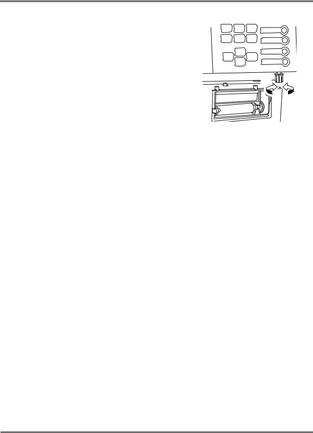
8 . 3 LCD Brightness Adjustment
Open the front cover of the instrument. LCD brightness can be adjusted using the brightness adjustment knob under the panel keyboard. Turning to the right brightens the light and turning to the left dims it.
Light Dark
9 . EMERGENCY STOP PROCEDURE
When there arises the need to stop the instrument urgently because of power outage, etc., in the laboratory, turn off the instrument power switch.
1 0 . ALARM SOUNDS
The KX-21 indicates different situations by five kinds of alarm sounds:
1. |
Key sound (single beep) |
|
Sounds about 0.1 second when a key on the panel keyboard is pressed. |
2. |
Input error sound (short beep) |
|
Sounds about 1 second when a wrong key is pressed on the panel keyboard. |
3. |
Analysis error sound (long beep) |
|
Sounds when an error occurs in the instrument and continues until you press [C] key |
|
or [HELP] key on the panel keyboard. |
4. |
Sound at sample aspiration |
|
Usually: A single "beep" when the start switch is pressed; "beep, beep" when |
|
aspiration is finished. |
Sample No. "0" or in pre-diluted mode: Beep sounds (beep, beep, ...) continue from pressing the start switch until aspiration ends.
1 1 . CONTENTS OF PACKAGE
The instrument is fully inspected before leaving the factory and carefully packed to withstand shocks in transit. Upon arrival, check the package to see that there is no external damage. Sysmex service representative will unpack, install the instrument, and make initial settings. To confirm the contents of the package, refer to "Appendix A: Installation."
Sysmex KX-21 Operator’s Manual -- Revised October 1998 |
1-11 |

INTRODUCTION
1 2 . INSTALLATION ENVIRONMENT
1 2 . 1 Installation and Relocation
The KX-21 is installed by Sysmex Service representative. In case relocation becomes necessary after installation, contact your Sysmex service representative.
Pay careful attention to this because if relocation, etc. of the instrument should be conducted by the customer, resulting in any trouble, warranty would not be applied even in the warranty period.
1 2 . 2 Grounding
The instrument power supply cord uses the 3-prong plug. When the power supply socket is 3-prong with grounding, simply plug it to the socket.
117 VAC Spec. |
220 VAC Spec. |
240 VAC Spec. |
Figure 1-12-1: Plugs
WARNING • Make sure to ground the instrument. Inadequate grounding could cause electrical shocks.
NOTE: • The number of power supply sockets required is one.
1-12 |
Sysmex KX-21 Operator’s Manual -- Revised October 1998 |

INTRODUCTION
1 2 . 3 Installation Space
To ensure that the instrument fulfills its function, it is important to install it at an appropriate place:
•Choose a place that is close to the power supply and proper waterway.
•Secure a place spacious enough for maintenance and service. Giving consideration to heat radiation by the instrument, provide at least 50 cm distance from the wall to side, rear, and top panels.
•Choose a place where reagent is easy to handle.
The instrument dimensions are shown below. The power supply cord is 1.8 m long, the waste tube up to 6 m long, and the diluent (CELLPACK) tube up to 2 m long.
|
Width (mm) |
Depth (mm) |
Height (mm) |
Weight (kg) |
Main Unit |
420 |
355 |
480 |
28 |
480
420
355
Figure 1-12-2: Instrument Dimensions
CAUTION: • When the diluent (CELLPACK) tube is more than 2 m long, it may be impossible to have reagent aspirated. Avoid setting CELLPACK at a level higher than the instrument; otherwise, reagent may flow into the vacuum line, possibly damaging the instrument.
Sysmex KX-21 Operator’s Manual -- Revised October 1998 |
1-13 |
 Loading...