


 Loading...
SERVICE MANUAL
Automated Blood Coagulation Analyzer
CA-500
Section 1 |
Specifications |
Section 2 |
Hydraulics and Mechanics |
Section 3 |
Electronics |
Section 4 |
Adjustment |
Section 5 |
Service Program |
Section 6 |
Error Messages and Troubleshooting |
Section 7 |
Schematics |
Appendix A |
Parts List |
Appendix B |
Installation |
Appendix C |
Disassembly |
SYSMEX CORPORATION
KOBE, JAPAN
SYSMEX CORPORATION, TECHNO CENTER 4-4-4 Takatsukadai, Nishi-ku, Kobe 651-2271, Japan TELEPHONE: 81-78-991-1911
FAX: 81-78-992-3274 URL=http://www.sysmex.co.jp
SYSMEX AMERICA, Inc.
1 Nelson C. White Parkway, Mundelein IL 60060, U.S.A.
TELEPHONE: 1-847-996-4500
FAX: 1-847-996-4505
URL=http://www.sysmex.com/
SYSMEX UK LIMITED
Sunrise Parkway, Linford Wood (East), Milton Keynes, Buckinghamshire, MK14 6QF, U.K. TELEPHONE: 44-1908-669555
FAX: 44-1908-669409
SYSMEX EUROPE GmbH
Bornbarch 1 22848, Norderstedt, Germany
TELEPHONE: 49-40-527260
FAX: 49-40-52726100
SYSMEX SINGAPORE PTE LTD.
2 Woodlands Sector 1, #01-06, Woodlands Spectrum Singapore 738068 TELEPHONE: 65-221-3629
FAX: 65-221-3687
Copyright © 1999 through 2001 by SYSMEX CORPORATION
First Edition |
November 1999 |
Second Edition |
December 2001 |
All right reserved. No part of this book may be reproduced in any form or by any electronic or mechanical means, including information storage and retrieval systems, without written permission from the publisher.
Printed in Japan
Part Code Number
Printed Manual: 601-8244-3
CD-ROM Manual: 601-8268-2

SECTION 1 SPECIFICATIONS |
To Cover |
||
1.1 |
Outline |
.................................................................................................................................................. |
1-1 |
1.2 |
Name and Model .................................................................................................................................. |
1-1 |
|
1.3 |
Configuration .............................................................................................................and Dimensions |
1-1 |
|
|
1.3.1 .......................................................................Configuration and Expandability of the System |
1-1 |
|
|
1.3.2 .......................................................................................................................... |
Power Source |
1-2 |
|
1.3.3 .......................................................................................................... |
Dimensions and Weight |
1-2 |
|
1.3.4 ..........................................................................................Each Unit Function and Operation |
1-2 |
|
|
1.3.5 ...................................................................................................... |
Principles of Measurement |
1-3 |
1.4 |
Performance, ....................................................................................Intended Use and Effectiveness |
1-3 |
|
|
1.4.1 ........................................................................................................................... |
Intended Use |
1-3 |
|
1.4.2 ............................................................................................................................ |
Performance |
1-3 |
|
1.4.3 ................................................................................................................................. |
Functions |
1-9 |
1.5 |
Acoustic ..........................................................................................................................Noise Level |
1-13 |
|
1.6 |
Environmental ...................................................................................................................Conditions |
1-14 |
|
|
1.6.1 ......................................................................................................... |
Operating Environment |
1-14 |
|
1.6.2 .............................................................................................................Reagents to be used |
1-14 |
|
1.7 |
How to ..................................................................................................................................Operate |
1-15 |
|
CA-500 Series S/M |
Revised December 2001 8 |

SECTION 1 SPECIFICATIONS
1.1OUTLINE
The Sysmex CA-500 Automated Blood Coagulation Analyzer obtains clotting times by detecting changes in scattered light intensity reflected from a diluted sample with buffer reagent which are illuminated by red light of LED.
Incubated plasma taken from the centrifuged sample blood is rapidly mixed with warmed reagent and coagulation is performed and analyzed. Its result can be automatically displayed and printed. In accordance with the way of coagulation the chromogenics substrate method and the method of immunoassay are optionally available on this unit .
1.2NAME AND MODEL
Name: |
AUTOMATED BLOOD COAGULATION ANALYZER |
Model: |
CA-510, CA-520, CA-530, CA-540, CA-550, CA-560 |
1.3CONFIGURATION AND DIMENSIONS
1.3.1Configuration and Expandability of the System
(1)Configuration
1)Main Unit (including Sampler Unit, Pneumatic Unit and Built-in Printer)
2)Chromogenic Unit and Bar Code Reader can be connected according to the following combinations as the factory option.
|
Reagent Cooler Unit |
Chromogenic Unit |
Immunoassay |
Bar Code Reader |
CA-510 |
– |
– |
– |
Option |
CA-520 |
– |
– |
– |
O |
CA-530 |
O |
O |
– |
Option |
CA-540 |
O |
O |
– |
O |
CA-550 |
O |
O |
O* |
Option |
CA-560 |
O |
O |
O* |
O |
*575 nm is used for Immunoassy.
(2)Factory Option
1)ID Bar Code Reader (optional supply is available for CA-510 and CA-530)
Sample ID numbers can be automatically read by Built-in Type Bar Code Reader (built in the sampler unit), which can scan the samples in one rack and the STAT sample. (CA-520, CA-540)
2)Chromogenic Unit
The chromogenic analysis is available on Chromogenic Unit built in Main Unit. (CA-530, CA-540)
3)Immunoassay Unit
The immunoassay is available on Immunoassay Unit built in Main Unit. (CA-550, CA-560)
4)Reagent Cooler Unit
Cooling reagent (for four parameters) is available on Reagent Cooler Unit built in Main Unit. (CA-530, CA-540)
(3)Interface with Other Instruments
1)RS-232C
2)PC-DPS(C), CA-DPS, SIS, or Host Computer can be connected.
CA-500 Series S/M |
1-1 |
Revised December 2001 8 |

1.3.2Power Source
(1) |
Rated voltage |
|
|
|
|
|
||
|
AC 100 V/117 V ± 10% |
|
|
|
|
|
||
|
AC 230 V ± 15% |
|
|
|
|
|
||
(2) |
Type of Current |
|
|
|
|
|
||
|
Direct Current |
|
|
|
|
|
||
(3) |
Frequency |
|
|
|
|
|
|
|
|
50 or 60 Hz |
|
|
|
|
|
||
(4) |
Maximum power consumption |
|
|
|
|
|||
|
Unit |
|
CA-510 |
CA-520 |
CA-530 |
CA-540 |
CA-550 |
CA-560 |
|
Main Unit |
|
310 VA or less |
320 VA or less |
380 VA or less |
400 VA or less |
380 VA or less |
400 VA or less |
(5) |
Class and Type of Electrical Protection |
|
|
|
|
|||
|
Class-I electrical apparatus, Type-B electrical apparatus |
|
|
|
||||
1.3.3Dimensions and Weight
(1)Dimensions (excluding projections)
540 mm (width) X 487 mm (height) X 470 mm (depth) ± 3% respectively
(2)Weight
Unit |
CA-510 |
CA-520 |
CA-530 |
CA-540 |
CA-550 |
CA-560 |
Main Unit |
43 kg |
44 kg |
44 kg |
45 kg |
44 kg |
45 kg |
1.3.4Each Unit Function and Operation
(1)Main Unit Power Switch Turns the power ON/OFF
(2)Display Unit
Displays the analysis registrations, analysis results, stored information and operation contents on the LCD.
(3)Control Unit
Using LCD and Touch Panel, controls the operation in dialog.
(4)XYZ Drive Mechanism
Dispenses sample and reagent. Transfers the reaction tubes.
(5)Mechanical Stop Switch
Stops the operation temporary.
(6)Detector Block
Determines the coagulation time by measuring changes in the intensity of light scattered by increasing turbidity.
(7)Chromogenic Unit
Detects the changes in the light absorbance by the transmitted light.
(8)Immunoassay Unit
Detects the changes in the light absorbance by the transmitted light.
(9)Temperature Control Unit
Controls temperatures for Detector Block, Reagent Heater Section and Cooling Section.
(10)System Control Unit Controls Main Unit system.
(11)Drive Circuit Unit
Controls each motor ‘s driving.
(12)Pneumatic Unit
(13)Sampler Unit
Enables the continuous automatic operations by the sampler. One sampler rack can contain 10 sample tubes.
CA-500 Series S/M |
1-2 |
Revised December 2001 8 |

1.3.5Principles of Measurement
1.3.5.1Biological Activation Method
(1)Coagulation Reaction Detection Method (Scattered Light Measuring Method):
Red light (660 nm) is irradiated onto the mixture of plasma and reagent and the change of the scattered light is detected, corresponding to the turbidity change when the fibrinogen is converted to fibrin.
(2)Coagulation End-Point Detection Method (Percent Detection Method):
Let the scattered light intensity at the time when the coagulation reagent is added to be 0% and that when the coagulation reaction is completed to 100. The coagulation time is obtained from the time to reach the presumed percent of the coagulation curve.
1.3.5.2Chromogenic Substrate Method
(1)Calorimetric Method Rate Method
1.4PERFORMANCE, INTENDED USE AND EFFECTIVENESS
1.4.1Intended Use
This unit measures the coagulation of the plasma or serum component of anti-coagulant (sodium citrate) added human blood.
1.4.2Performance
(1) Measurement Parameters and Display Parameters (Default Unit is shown in [ ]).
1) |
Prothrombin Time (PT) |
[second] |
||
|
Calculated Parameters: |
|
|
|
|
(a) |
Prothrombin Activation Percent |
|
[%] |
|
(b) |
Prothrombin Ratio |
|
[ – ] |
|
(c) International Normalized Ratio (INR) |
|
[ INR ] |
|
|
(d) Derived Fbg (for export specification only) |
|
[mg/dL] |
|
2) |
Activated Partial Thromboplastin Time (APTT) |
[second] |
||
|
Calculated Parameters: |
|
|
|
|
(a) |
APTT Ratio |
|
[ – ] |
|
(b) Activation Percent (for European and UK specifications only) |
[% ] |
||
3) |
Fibrinogen (Fbg) |
[second] |
||
|
Calculated Parameters: |
|
|
|
|
(a) |
Fibrinogen Concentration |
|
[mg/dL] |
4) |
Thrombo Test (Plasma Method) |
[second] |
||
|
Calculated Parameters: |
|
|
|
|
(a) |
Activation Percent |
|
[%] |
|
(b) INR (for European and UK specification only) |
|
[ – ] |
|
CA-500 Series S/M |
1-3 |
Revised December 2001 8 |

5) |
Normotest (NT) |
[second] |
|
|
Calculated Parameters: |
|
|
|
(a) |
Activation Percent |
[%] |
|
(b) INR (for European and UK specification only) |
[ – ] |
|
6) |
Thrombin Time (for export specifications only) |
[second] |
|
7) |
Factor (II, V, VII, VIII, IX, X, XI, XII) |
[second] |
|
|
Calculated Parameters: |
|
|
|
(a) |
Activation Percent |
[%] |
8) |
Protein C Coagulum (PCc) |
[second] |
|
|
Calculated Parameters: |
|
|
|
(a) |
Activation Percent |
[%] |
(9) |
Batroxithonbin (BXT) |
[second] |
|
(10) |
LA1, LA2 |
[second] |
|
[Options] |
|
|
|
(11) |
Anti-thrombin III (AT-III) |
[%] |
|
(12) |
α2 Anti-plasmin (APL) |
[%] |
|
(13) |
Anti-plasminogen (Plg) |
[%] |
|
(14) |
Protein C (PC) |
[%] |
|
(15) |
Heparin (Hep) |
[%] |
|
|
International Unit |
[IU/mL] |
|
(16) |
FDP (SFDP) |
[µg/mL] |
|
(17) |
Plasma FDP (PFDP) |
[µg/mL] |
|
(18) |
D-Dimer (DPI/DD) |
[g/mL] [µg/mL] |
|
(2)Measurement Ranges
1)Fbg
Measuring is possible from 25 mg/dL to 1000 mg/dL of the fibrinogen concentration.
(In case of 450 mg/dL or above, measurement is performed with automatic re-dilution in high Fbg concentration mode, and in case of 50 mg/dL or less, in low Fbg concentration mode. In CA-550 and CA-560, measurement for 900 mg/dL or above is performed in high Fbg concentration mode, and for 100 mg/dL or less, in low Fbg concentration mode. )
2)D-Dimer (CA-550 and CA-560 only)
With applicable reagents, measuring is possible from 50 to 9999 µ/gL. However, the concentration of 2000 µ/gL or above is measureed in 8-hold dilution mode (+D-Dimer).
3)Serum FDP(CA-550 and CA-560 only)
With applicable reagents, measuring is possible from 2.5 to 320 µg/mL . However, the concentration of 40 µg/mL or above is measureed in 8-hold dilution mode (+PFC).
4)Plasma FDP (CA-550 and CA-560 only)
With applicable reagents, measuring is possible from 2.5 to 480 µg/mL. However, in the concentration of 60 µg/mL or above, measurement is performed in 8-hold dilution mode (+PFC).
CA-500 Series S/M |
1-4 |
Revised December 2001 8 |

(3)Measurement Time
1)Maximum Measurement Time in Standard Mode
PT |
100 seconds (120 seconds in CA-550 and CA-560) |
Fbg |
100 seconds |
Others |
190 seconds |
ATIII |
30 seconds |
2)Maximum Measurement Time in Automatic Extended Mode
All Parameters |
600 seconds |
(4)Accuracy
When control plasma N is measured consecutively 10 times, measurement error of the average time (second) should lie within the following ranges. (The ambient temperature must be 25 ± 10°C.)
PT |
± 8% or less |
APTT |
± 8% or less |
(5)Reproducibility
Coefficient of variation, when control plasma N is measured consecutively 10 times, should lie within the following ranges with 95 % confidence if specified reagents are used. The ranges should be observed when measuring was performed on 10 to 30 µg/mL of diluent sample with SFDP and PFDP, and on 500 to 1000 µg/mL of diluent sample with D-Dimer.
PT, APTT |
[second] |
CV within 2% |
TTO, NT |
[second] |
CV within 4% |
Fbg |
[second] |
CV within 4% |
Factor (II, V, VII, VIII, IX, X, XI, XII) |
||
|
[second] |
CV within 5% |
TT |
[second] |
CV within 10% |
BXT |
[second] |
CV within 4% |
LA1/LA2 |
[second] |
CV within 4% |
PCc |
[second] |
CV within 5% |
AT-III |
[%] |
CV within 5% |
APL |
[%] |
CV within 5% |
Plg |
[%] |
CV within 5% |
BCPC |
[%] |
CV within 5% |
Hep |
[IU/mL] |
CV within 5% |
SFDP |
[µg/mL] |
CV within 10% |
PFDP |
[µg/mL] |
CV within 10% |
D-Dimmer |
[µg/L] [µg/mL] |
CV within 10% |
CA-500 Series S/M |
1-5 |
Revised December 2001 8 |

(6)Stability
1)Temperature Stability
Variation of measurement (Activation % for AT III) at 15°C (C15) or 35°C (C35) from that at 25°C (C25) lies within the following ranges, when this formula is used.
|
|
C15 (or C35) - C25 |
|
|
x 100 |
|
|
|
|
||
|
|
|
|
|
|
|
|
C25 |
|
||
|
|
|
|
|
|
PT, APTT (second) |
± 8% or less |
||||
Fbg, TTO, HpT (second) |
± 10% or less |
||||
AT III (%) |
± 10% or less |
||||
D-Dimmer (µg/L) |
± 10% or less |
||||
2)Stability within-a-day
Variation of measurement (Activation % for AT III) at the time of 2, 4 and 8 hours from that at 30 minutes after the power is turned on (initial value) lies within the following ranges. The ambient temperature at the time of measurement should be within the specified range. Temperature variation must be within 5°C.
( Measurement after 2, 4 or 8 hours ) - ( Measurement at 30 minutes )
x 100
( Measurement at 30 minutes )
PT, APTT (second) |
± 8% or less |
Fbg, TTO, HpT (second) |
± 10% or less |
AT III (%) |
± 10% or less |
D-Dimmer (µg/L) |
± 10% or less |
3)Long-term Stability (daily variation)
Variations in measurement values (Activation % for AT III) during the continuous 10 days lie within the following ranges. The ambient temperature at the time of measurement should be within the specified range. Temperature variation must be within 5°C.
( Measurement after second day ) - ( Mean Measurement )
x 100
( Mean Measurement )
PT, APTT (second) |
± 8% or less |
Fbg, TTO, HpT (second) |
± 10% or less |
AT III (%) |
± 10% or less |
D-Dimmer (µg/L) |
± 10% or less |
4)Stability against Power Source Variation
Variation of measurement (Activation % for AT III) lies within the following ranges when the rated voltage changes at ±10%.
( Measurement at +10% or -10% ) - ( Measurement at rated voltage )
x 100
( Measurement at rated voltage )
PT, APTT (second) |
± 8% or less |
Fbg, TTO, HpT (second) |
± 10% or less |
AT III (%) |
± 10% or less |
D-Dimmer (µg/L) |
± 10% or less |
CA-500 Series S/M |
1-6 |
Revised December 2001 8 |

(7)Analysis Mode and Sample Throughput
1)Analysis Mode
5 parameters are selected out of 7 parameters (14 parameters in CA-550 and CA-560) to perform random analysis.
2)Sample Throughput
Maximum Throughput: approx. 54 tests/hour (when PT single parameter is measured) Mean Throughput (PT, APTT, Fbg): approx. 40 tests/hour (when three parameters are measured at
the same time)
Mean throughput in this case means the mean throughput at the point of which an hour has passed from
a Start-key entry.
(8)Time Resolution
1)Coagulation
Time resolution is as follows depending on the elapsed time from the start of measurement.
0.1 second |
2 through 120 seconds |
0.2 second |
120 through 240 seconds |
1.0 second |
240 through 600 seconds |
2)Chromogenics Substrate Method and Immunoassay Method
The unit can continue performing sampling every second up to 600 seconds at maximum.
(9)Compensation functions
1)Setting of Coagulation Detection End Point
The coagulation detection point can be set every 1% within the range of 2 to 80%, enabling the data calibration.
2)External compensation Function
The measured data is corrected with the linear equation.
(10)Required Volume of Plasma and Reagent
The required sample amount for each parameter and the required volume of reagent for the measurement of one sample are shown below. (Unit in µL)
Parameter |
Sample/Reagent |
Quantity |
|
(1) |
PT |
Citrated Plasma |
50 |
|
|
Pt |
100 |
(2) |
APTT |
Citrated Plasma |
50 |
|
|
Aptt |
50 |
|
|
CaC12 |
50 |
(3) |
Fbg |
Citrated Plasma |
5 |
|
|
Owren’s Veronal buffer |
95 |
|
|
Fbg |
50 |
(4) |
TTO |
Citrated Plasma |
20 |
|
|
Owren’s Veronal buffer |
30 |
|
|
CA-Series Comlex Factor TTO |
125 |
(5) |
HpT |
Citrated Plasma |
10 |
|
|
Owren’s Veronal buffer |
40 |
|
|
CA-Series Complex Factor HPT |
125 |
(6) |
TT |
Citrated Plasma |
100 |
|
|
Owren’s Veronal buffer |
50 |
(7) |
II, V, YII, X |
Citrated Plasma |
5 |
|
|
Owren’s Veronal buffer |
45 |
|
|
Factor Deficient Plasma |
50 |
|
|
PT |
100 |
(Continues to the next page.)
CA-500 Series S/M |
1-7 |
Revised December 2001 8 |
|
|
(Continued from the previous page.) |
|
Parameter |
Sample/Reagent |
Quantity |
|
(8) VII, IX, XI, XII |
Citrated Plasma |
5 or 10 |
|
|
|
Owren’s Veronal buffer |
45 or40 |
|
|
Factor Deficient Plasma |
50 |
|
|
APTT |
50 |
|
|
Calcium Chroride |
50 |
(9) |
PC.c |
Citrated Plasma |
5 |
|
|
Protein C Deficient Plasma |
35 |
|
|
Protein C Activator |
40 |
|
|
APTT |
40 |
|
|
Calcium Chloride |
40 |
(10) |
BXT |
Citrated Plasma |
50 |
|
|
Batroxobin |
100 |
(11) |
La1 |
Citrated Plasma |
100 |
|
|
LA1 |
100 |
|
La2 |
Citrated Plasma |
100 |
|
|
LA2 |
100 |
(12) |
AT3 |
Citrated Plasma |
10 |
|
|
Owren’s Veronal buffer |
83 |
|
|
Thrombin Reagent |
125 |
|
|
Substrate Reagent |
33 |
(13) |
APL |
Citrated Plasma |
16 |
|
|
Owren’s Veronal buffer |
83 |
|
|
Plasmin |
125 |
|
|
Plasmin Substrate |
33 |
(14) |
Plg |
Citrated Plasma |
16 |
|
|
Owren’s Veronal buffer |
112 |
|
|
Streptkinase Reagent |
125 |
|
|
Plasmin Substrate |
25 |
(15) |
BCPC |
Citrated Plasma |
20 |
|
|
Protein C Activator |
125 |
|
|
Substrate Reagent |
30 |
(16) |
Hep |
Citrated Plasma |
20 |
|
|
ATIII Reagent |
20 |
|
|
Factor Xa Reagent |
125 |
|
|
Heparin Substrate |
40 |
(17) |
DDPI |
Citrated Plasma |
50 |
|
AdDD |
Accelerator |
25 |
|
|
Latex |
150 |
(18) |
DD |
D-D Dimer Standard |
16 |
|
|
Elpia Ace D-D Dimer Stabilizer |
116 |
|
|
Elpia Ace D-D Dimer Latex |
33 |
|
|
Elpia Ace D-D Dimer Diluent |
112 |
(19) |
SFDP |
Standard Set For Elpia FDP |
10 |
|
|
Elpia FDP Stabilizer |
122 |
|
|
Elpia FDP Latex |
22 |
|
|
Owren’s Veronal buffer |
97 |
(20) |
PFDP (in 800 nm analysis) |
P-Fdp Standard |
16 |
|
|
Latex Test BL-2 P-FDP Diluent |
66 |
|
|
Latex Test BL-2 P-FDP Latex |
94 |
|
|
P-FDP Diluent |
80 |
(21) |
PFDP (in 575 nm analysis) |
P-FDP Standard |
16 |
|
|
Latex Test BL-2 P-FDP Diluent |
66 |
|
|
Latex Test BL-2 P-FDP Latex |
94 |
|
|
P-FDP Diluent |
112 |
Additionally, approximately 6 mL of distilled water and approximately 212 µL (at the maximum) of rinsing solution (CA CLEAN I) are required for rinsing per test.
CA-500 Series S/M |
1-8 |
Revised December 2001 8 |

1.4.3Functions
(1)Sample Tube Transportation Function
Sample tube is transported from the sample tube rack to the sample incubation unit by the Slide Catcher Method.
(2)Reaction Tube Feeding Function
1) |
Reaction Tube Feeding Method: |
Fed manually to Reaction Tube Rack |
2) |
Number of Reaction Tube: |
2 racks containing 30 tubes each (maximum 60 reaction tubes) |
3) |
Kinds of Reaction Tube: |
Tube SU-40 for CA-1000 |
4) |
Detecting Reaction Tube: |
Detected by Reaction Tube Detective Sensor |
(3)Sample Plasma and Reagent Dispensing Function
One dispensing pipette with the heating function moves up and down, traverses, and dispenses the sample and the reagent.
1) |
Temperature Control Accuracy: |
37.0 ± 1.0°C (with ambient temperature of 15 ~ 30°C) |
2) |
Waiting Time for Setting Temp.: |
within 30 minutes |
3) |
Volumetric Method: |
Sample and reagent are aspirated, dispensed and rinsed by the |
|
|
syringe. |
4) |
Volumetric Syringe: |
1 |
5) |
Pipette: |
1 |
(4)Liquid Surface Detection Function
The pipette has the liquid surface detection function, so that it senses the meniscus automatically and then stops at a certain depth of the sample or the reagent.
(5)Sampler Function
1) |
Sample Storing Method: |
Sysmex Rack |
2) |
Maximum Sample Storage: |
1 rack (10 samples) |
3)Usable Collection Tubes:
The following types with inside diameter of 8 mm or more.
(i)15 (OD) X 75 ~ 100 mm length
(ii)12 (OD) X 75 ~ 100 mm length
(iii)10 (OD) X 65 mm length (The optional spacer is required.)
(iv)Sample cup of 2 mL or 4 mL
4) |
Sample Cooling Function: |
None |
5) |
Sample ID Reading Function: |
Sample ID No. can be read by the Bar Code Reader. |
(6)STAT Sample Measurement Function
1)The specified sample in the STAT Sample Rack can be analyzed, interrupting the usual analysis. Within 10 minutes from the interruption by the STAT sample analysis, the analysis result can be output (when the single parameter is analyzed).
2)Number of STAT sample One sample only.
(7)Measurement Interrupt/Restart Function (CA-550 and CA-560 only)
The analyzer has the function to allow setting additional samples to the rack in process after starting a measurement and measuring them. The registration of the additional samples can be made on the left side from the left-end tube position for the samples already set in rack and registered for measurement.
CA-500 Series S/M |
1-9 |
Revised December 2001 8 |

(8)Reagent Storage Function
1) |
Reagent Storage Method: |
|
Stored in the reagent rack |
|
|
|||
2) |
Reagent holder capacity: |
|
Maximum 10 kinds of reagent bottles can be set in the reagent |
|||||
|
|
|
|
rack. Buffer and rinsing solution can also be set. |
||||
3) |
Usable container: |
|
Dade Bering’s old DADE for 5 mL, a sample cup, can be set, and |
|||||
|
|
|
|
also GW5, a new type of reagent bottles only for |
||||
|
|
|
|
CA-550/CA-560, can be set. |
|
|
||
|
|
|
|
(The outer diameter of the reagent bottle should be less than |
||||
|
|
|
|
22.5 mm, and also, if the inner diameter is too small, use the |
||||
|
|
|
|
bottle adapter.) |
|
|
||
4) |
Reagent Cooling Function: |
|
Four reagents can be cooled. (CA-530, CA-540) |
|||||
5) |
Temperature Control Accuracy: |
within 15 ± 2°C (Room temperature: 15°C - 30°C) |
||||||
6) |
Waiting time for setting temp.: |
within 30 minutes |
|
|
||||
7) |
Reagent Mixing Function: |
|
None |
|
|
|
|
|
|
Type of reagent |
|
Number of |
Cooling function |
|
Container which can be |
|
|
|
|
accommodation |
|
|
accommodated |
|
||
|
PT |
|
|
1 |
Yes |
|
|
|
|
APTT |
|
|
2 |
No |
|
DADE 5 mL Reagent Bottle |
|
|
Fbg |
|
|
1 |
Yes |
|
|
|
|
TTO |
|
|
1 |
No |
|
(with outer diameter of |
|
|
NT |
|
|
1 |
No |
|
22.3 mm) |
|
|
TT |
|
|
1 |
Yes |
|
|
|
|
AT-III |
|
|
2 |
Yes (only one) |
|
|
|
|
Buffer |
|
|
1 |
No |
|
|
|
|
CA CLEAN I |
|
|
1 |
No |
|
|
|
(9)Detection Function
1)Principle of Measurement [Coagulation Method]: [Chromogenic Method]: [Immunoassay]:
2)Number of Detectors [Coagulation Method]: [Chromogenic Method]: [Immunoassay]:
3)No. of Incubation wells:
4)Temperature Control Accuracy:
5)Waiting time for setting temp.:
(10)Pipette Rinsing Function
Scattered Light Measuring Method (wave length 660 nm) Calorimetric method (wave length 405 nm)
Colorimetric method (wave length 575 nm)
4 detection wells (High and Low sensitivity automatic switching)
1 detection well
1 detection well
6 wells
within 37.0 ± 0.5°C (ambient temperature: 15°C-30°C) within 37.0 ± 1.0°C for Incubation Well
within 30 minutes
1) |
External Container: |
Rinse Bottle and Waste Bottle |
|
2) |
Rinse Cup: |
Probe Rinse Cup (Outside) and Probe Rinse Cup (Inside) |
|
3) |
Rinsing Function: |
Pipette is rinsed by controlling the syringe and the solenoid valve, with |
|
|
|
applying the pressure on the Rinse Bottle. |
|
4) |
Waste Draining: |
The waste is aspirated by controlling the |
solenoid valve, with applying |
|
|
vacuum on the waste bottle. |
|
CA-500 Series S/M |
1-10 |
Revised December 2001 8 |

(11)XYZ Driving Function
Pipette and sample catcher mechanism on the head unit (Z axis) is driven by the XY-axis mechanism to dispense sample and reagent and transfer and discard the reaction tubes.
1) |
XY-axis Mechanism: |
Linear Slider driven by stepper motor |
2) |
Z-axis Mechanism: |
Pipette and sample tube catcher are driven by one motor. |
(12)Mixing Function
After dispensing the reagent, the reaction tube is vibrated and mixed by the miniature motor.
(13)Sample Data Storage Function
1)Contents of Data
(i)Measurement data
(ii)Setting values
(iii)Quality control data
(iv)Date (year, month, day, hour, minute)
2)Memory Capacity
(i)Data of 300 samples (maximum 1500 tests = 300 samples X 5 parameters). The analysis print data is not stored once the power is OFF. As for the reaction curve, the latest 600 tests are stored.
(ii)Quality control data: 12 kinds X 7 parameters X 180 plots (CA-510 to CA-540)
6 kinds X 14 parameters X 180 plots. To the Quality Control file, the parameters of dilution magnification such as -Fbg, +Fbg, +DD, +DDPl, +SFD, and +PFD are also included. (CA-550 and CA-560 only)
(14)Display and Input Function
1)Display Type
Graphic panel display + touch panel using a 3.2 X 4 inch liquid crystal display (white and black back light)
2)Displayed Data
(i)Date
(ii)Measurement condition, Analysis status, Results
(iii)Stored sample: Stored sample list: Date, Time, Sample ID number, Parameter name, Measured data, Reaction curves (CA-550 and CA-560 allow zooming in to view), Rack number. (CA-550 and CA-560 only).
(iv)Quality control (QC data, QC chart)
(Only CA-550 and CA-560 can carry markings on screen display about the data beyond the upper and lower limits of quality control. In addition, the CA-550 and CA-560 analyzers stores the data of slight coagulation errors.)
(v)Standard curve (SC data, SC chart)
(vi)Operation messages
(vii)Error messages
(viii)Maintenance information and various setting values
(ix)Temperatures at incubation well, heater pipette, reagent cooler unit
3)Input Method
Change, select, and set functions on each screen by LCD touch panel method.
CA-500 Series S/M |
1-11 |
Revised December 2001 8 |

(15)Printing Function
1)Printing Method
Graphic print by a built-in thermal printer
2)Printed Data
(i)Stored sample data (the same as the measured data)
(ii)Quality control (QC data, QC chart)
(iii)Measured data (Date, Time, Sample ID number, Parameter name, Measured data, Reaction curve, Analysis print data, Rack number (CA-550 and CA-560 only))
(iv)Standard curve (SC data, SC chart)
(v)Confirmation messages, Error messages
(vi)Maintenance information and various setting values (CA-550 and CA-560 can print at each parameter.)
(16)Quality Control Function
1)L-J control or X control is possible using control material.
2)Applicable parameters: PT, APTT, Fbg, TTO, NT, TT, AT III
14 parameters (CA-550 and CA-560 only)
-Fbg, +Fbg, +DD, +DDPl, +SFD, and +PFD are also treated as parameters and QC analysis can be performed on each parameter. (CA-550 and CA-560 only)
3) Number of stored files: 12 files for each parameter
67files (CA-550 and CA-560 only)
4)Number of data points: 180 for each parameter
(17)Select Function
1)Measurement Mode
(i)Random access measurement mode
5 parameters are selected out of 7 parameters (14 parameters in CA-550 and CA-560) and the five parameters are measured at random.
(ii)Programmable measurement mode
All parameters are measured with changing the measurement order.
(iii)Replication mode
The same sample is measured twice (or more) and the mean value is determined to be the measurement result. However, the throughput is less than half number of that of ordinary measurement.
2)Settings
(i)Sample ID number
(ii)Date/Time
(iii)Setting function for APTT heating time
2, 3, 4 or 5 (minutes) of heating time can be set. (Standard setting is 3 minutes and the throughput changes if other time is set.)
3)Output
Automatic transfer or Manual transfer can be set.
Raw data output is available in Service mode. (CA-550 and CA-560 only)
4)Stored data processing
Displaying and printing the stored data is possible.
5)Service Function
For the Customer: |
Displaying of standard curve data and setting of abnormal values |
|
(range) |
For the Servicing Personnel: |
Service mode, System tests, Memory Initialization, and |
|
adjustment/setting (of X-Y axis position) |
CA-500 Series S/M |
1-12 |
Revised December 2001 8 |

(18)Standard Curve Setting Function
Standard curve of seven parameters (14 parameters in CA-550 and CA-560) can be set at six points or less within the measurable range. Setting Standard Curve is performed by the Auto dilution or Manual Entry. (Manual dilution analysis is available only in CA-550 and CA-560.) Two kinds of standard curves can be set to one parameter (only in CA-550 and CA-560). Settings should be given to each parameter individually.
(19)Analytical Algorithm corresponding to V-Lin-Integral (CA-550 and CA-560 only)
As a new analysis method, analytical algorithm equivalent to V-Lin-Integral is provided.
(20)APTT Initial Reaction Check Algorithm (CA-550 and CA-560 only) An algorithm to check APTT’s initial reactions is newly provided.
(21)Detector Block Self-Checking Function (CA-550 and CA-560 only)
Besides the already-provided functions to adjust the detector block, a function is newly provided that the analyzer self-monitors the state of the detector block and carry out auto calibration.
(22)Error Alert Function
1)Unit Error monitoring function
(i)Temperature of heater section
(ii)Shortage of reagent
(iii)Presence or absence of sample rack
(iv)Shortage of rinse solution
(v)Overflow from the waste bottle
(vi)Operation of mechanical parts
(vii)Operation of printer
(viii)Shortage of printer paper
(ix)Serial output
(x)Other self-diagnosis by service mode
2)Sample Abnormality monitoring function
(i)Upper and lower limit judgment (PT, APTT, Fbg, TTO, NT, TT, AT-III) Display when the measured data exceeds the preset range.
(23)External Input/Output Function
The I/O terminal in accordance with RS-232C is provided as bit serial voltage I/O.
(24)Protection Function
1)Over-heat protection thermal fuse (Pipette Unit and Detector Block)
2)Mechanical stop switch
3)Light Shield cover open/close switch
4)Sampler position sensor
(25)Display Languages
Capable of displaying six languages such as Japanese, English, French, Italian, German, and Spanish. Screen displays and messages should be consistent with those of existing models.
1.5ACOUSTIC NOISE LEVEL
Noise level should be within the following values. (The measuring position is 1 meter from the front of the product.
(1) |
Stand-by status: |
58 dB or less |
(2) |
Measuring operation status: |
60 dB or less |
Temporary noises (less than 65 dB continued within 5 seconds) are produced on occasions, such as home positioning of X-Y table or syringe drive mechanism are not included.
CA-500 Series S/M |
1-13 |
Revised December 2001 8 |

1.6ENVIRONMENTAL CONDITIONS
1.6.1Operating Environment
(1) |
Ambient temperature: |
15 |
~ 35°C |
(2) |
Relative humidity: |
30 ~ 85% (non-condensing) |
|
(3) |
Atmospheric pressure: |
70 |
~ 106 kPa |
(4) |
Place to be installed: |
avoid direct sunlight, dust, vibration and acid vapors |
|
1.6.2Reagents to be used
Parameter |
Reagent |
PT |
Thromborel S |
|
Dade Innovin |
|
Dade Thromboplastin C plus |
APTT |
Pathromtin SL |
|
Dade Actia Activated Cephanloplastin Reagent |
|
Dade Actia FS Activated FTT Reagent |
|
Dade Actia FSL Activated FTT Reagent |
|
Calcium Chroloride Solution (0.025 mol/l) |
Fbg |
Dade Thrombin Reagent |
TT |
Thrombin Clotting Time Reagent |
II |
Clotting Factor-II Deficient Plasma |
V |
Clotting Factor-V Deficient Plasma |
YII |
Clotting Factor-VII Deficient Plasma |
X |
Clotting Factor-X Deficient Plasma |
VIII |
Clotting Factor-VIII Deficient Plasma |
IX |
Clotting Factor-IX Deficient Plasma |
XI |
Clotting Factor-XI Deficient Plasma |
XII |
Clotting Factor-XII Deficient Plasma |
LA1/LA2 |
LA1 Screening Reagent/LA2 Confirmation Reagent |
PC.c |
Protein C reagent |
BXT |
Batroxobin reagent |
AT3 |
Berichrom Antithrombin (A) |
APL |
Berichrom α2-Antiplasmin |
Plg |
Berichrom Plasminogen |
BCPC |
Berichrom Protein C |
Hep |
Berichrom Heparin |
PFDP |
Latex Test BL-2 P-FDP |
|
P-FDP Diluents |
DDPI/AdDD |
D-Dimer PLUS/Advanced D-Dimer |
|
Control Plasma N(Human) |
|
Control Plasma P(Human) |
|
DadeCi-Trol Coagulation Control,Level 1 |
|
DadeCi-Trol Coagulation Control,Level 2 |
|
DadeCi-Trol Coagulation Control,Level 3 |
|
Standard Human Plasma |
|
P-FDP Standard |
|
D-Dimer PLUS Standard Plasma |
|
PT Calibration Plasma Kit |
|
CA CLEAN |
|
CA CLEAN |
CA-500 Series S/M |
1-14 |
Revised December 2001 8 |

1.7HOW TO OPERATE
Check
Instrument
Power ON
Analysis
Preparation
Start Analysis
Result Output
•Check the rinse solution (distilled water) to make sure that the analyzer is ready for operation.
•Turn the instrument power ON 30 minutes before the analysis.
•Dissolve reagents 30 minutes before the analysis. Set the reagents to the reagent holder.
Execute the quality control to check the instrument condition.
•Set the sample to the sampler. Enter sample orders to be analyzed. Press the [Start] key to start analysis.
•The analysis results will be displayed on LCD and printed out on printer paper.
|
|
• Remove the reagents and the sample. |
End Analysis |
||
|
|
• Execute the daily maintenance for the next analysis. |
Shutdown |
||
|
|
• Rinse the pipette and turn the instrument power OFF. |
Power |
OFF |
|
CA-500 Series S/M |
1-15 |
Revised December 2001 8 |

SECTION 2 HYDRAULIC/MECHANICAL SYSTEMS |
|
To Cover |
||
2.1 |
TUBING DIAGRAM.............................................................................................................................. |
2-1 |
||
2.2 |
HYDRAULIC SYSTEM OPERATION .................................................................................................. |
2-2 |
||
|
2.2.1 |
Structure................................................................................................................................ |
2-2 |
|
|
2.2.2 |
Operation............................................................................................................................... |
2-2 |
|
2.3 |
PRESSURE CIRCUIT.......................................................................................................................... |
2-4 |
||
|
2.3.1 |
Structure................................................................................................................................ |
2-4 |
|
|
2.3.2 |
Operation............................................................................................................................... |
2-4 |
|
2.4 |
DETECTOR BLOCK............................................................................................................................ |
2-5 |
||
|
2.4.1 |
Outline ................................................................................................................................... |
2-5 |
|
|
2.4.2 |
Specifications/Functions........................................................................................................ |
2-5 |
|
|
2.4.3 |
Assembly Diagram ................................................................................................................ |
2-5 |
|
2.5 |
REAGENT COOLING UNIT ................................................................................................................ |
2-6 |
||
|
2.5.1 |
Outline ................................................................................................................................... |
2-6 |
|
|
2.5.2 |
Specifications/Functions........................................................................................................ |
2-6 |
|
|
2.5.3 |
Assembly Diagram ................................................................................................................ |
2-6 |
|
2.6 |
VOLUMETRIC UNIT ............................................................................................................................ |
2-7 |
||
|
2.6.1 |
Outline ................................................................................................................................... |
2-7 |
|
|
2.6.2 |
Specifications/Functions........................................................................................................ |
2-7 |
|
|
2.6.3 |
Assembly Diagram ................................................................................................................ |
2-7 |
|
2.7 |
X-Y DRIVE UNIT (X-AXIS MOTOR ASSEMBLY/DRIVE-AXIS ARM ASSEMBLY) |
.............................2-8 |
||
|
2.7.1 |
Outline ................................................................................................................................... |
2-8 |
|
|
2.7.2 |
Specifications/Functions........................................................................................................ |
2-8 |
|
|
2.7.3 |
Assembly Diagram ................................................................................................................ |
2-8 |
|
2.8 |
Z-AXIS DRIVE UNIT (Z-AXIS BASE ASSEMBLY) .............................................................................. |
2-9 |
||
|
2.8.1 |
Outline ................................................................................................................................... |
2-9 |
|
|
2.8.2 |
Specifications/Functions........................................................................................................ |
2-9 |
|
|
2.8.3 |
Assembly Diagram ................................................................................................................ |
2-9 |
|
2.9 |
BAR CODE READER UNIT (ID COMPLETED PARTS) ................................................................... |
2-10 |
||
|
2.9.1 |
Outline ................................................................................................................................. |
2-10 |
|
|
2.9.2 |
Specifications/Functions...................................................................................................... |
2-10 |
|
2.10 |
PUMP UNIT (PRESSURE PUMP/VACUUM PUMP COMPLETED PARTS) .................................... |
2-11 |
||
|
2.10.1 |
Outline ................................................................................................................................. |
2-11 |
|
|
2.10.2 |
Specifications/Functions...................................................................................................... |
2-11 |
|
|
2.10.3 |
Assembly Diagram .............................................................................................................. |
2-11 |
|
CA-500 Series S/M |
Revised December 2001 8 |

SECTION 2 HYDRAULIC/MECHANICAL SYSTEMS
2.1TUBING DIAGRAM
|
|
|
|
|
Probe Rinse Cup (Outside) |
|
|
|
|
|
MAIN (PCNo.6362) |
|
Probe Rinse Cup (Inside) |
|
|
||
|
|
|
|
|
|
|
||
|
|
|
|
Rubber Tube No. 7 |
Si4 (95) |
|
|
|
|
|
|
|
|
|
|
|
|
|
|
|
|
TF2 (450) |
|
|
|
Trash Box |
|
|
|
SV No.14 |
Rinse Cup |
|
|
||
|
|
|
|
|
|
|||
|
|
|
|
|
|
|
|
|
|
|
Si1 |
TA |
|
|
|
TF1 (1600) |
|
|
|
(620) |
|
|
|
|
|
|
|
|
(100) |
|
|
|
|
|
|
|
|
|
|
|
|
|
|
|
Pressure |
Si2 |
(240) |
|
|
LFAA |
|
|
|
|
|
|
|
Si3 1201518H |
|
|
|
|
Pump |
|
|
|
TA (250) |
TF1 |
|
|
|
|
Chamber No. 4 |
|
(12) |
Volumetric |
Pipette |
|||
|
|
|
|
(200) |
||||
|
|
|
|
|
|
|||
|
|
|
|
Hydraulic Connector |
Piston |
|
||
|
|
|
|
|
|
|||
|
|
TA |
TA |
No. 23 |
|
|
|
|
(520)(80)
Vacuum |
TA (160) |
|
|
|
Si2 |
M |
Pump |
|
|
|
|
(530) |
|
|
|
B |
B |
S |
B |
|
|
|
|
|
|
Rear Panel |
|
|
Si2 |
black blue |
red |
green |
Si2 (200) |
|
|
|
|
|
|
||
|
|
|
|
|
|
|
|
(240) |
Si2 |
|
|
|
|
|
Check Valve |
|
|
|
|
|
|
(240) |
|
|
|
|
|
|
Si2 |
Filter |
|
Si2 |
Si2 |
|
|
Si2 |
|
|
|||
|
(240) |
(500) |
(500) |
|
||
|
|
(240) |
|
|
|
|
Trap Chamber
No. 7Assy
Rinse Bottle |
Waste Bottle |
Si2
(500)
Si1: Tube Silicone 2 x 5
Si2: Tube Silicone 4 x 8
Si3: Tube Silicone 1/32 x 3/32 inches Si4: Tube Silicone 6 x 10
TF1: Tube Teflon 1.2 x 2.0
TF2: Tube Teflon 1.5 x 2.5
TA: Tube Toalone 3 x 6
B:Connecting Tube No. 50
C:Connecting Tube No. 3
S:Nipple No. 123
CA-500 Series S/M |
2-1 |
Revised December 2001 8 |
2.2HYDRAULIC SYSTEM OPERATION
2.2.1Structure
The hydraulic system consists of the volumetric syringe for volumetric dispensing of samples or reagent, the filling line using the pressure pump and solenoid valve, and the drain line using the vacuum pump.
2.2.2Operation
(1)Outline of Hydraulic System Operation
This system's filling and draining are operated by pressure created by the pressure pump and vacuum pump in the system. Therefore the pressure is applied to the rinse bottle and the vacuum is applied to the waste bottle.
(a)Filling line
A constant pressure is applied to the rinse bottle. The valve connected to the line opens to feed rinse solution.
(b)Drain Line
The drain line is released to the atmosphere at the rinse cup. The vacuum pump operates only when the vacuum to aspirate the waste into the waste bottle. The vacuum is not monitored. Instead, instrument checks if the liquid level becomes abnormal when the sample probe is moved to the Probe Rinse Cup (inside) (if liquid is not drained properly, the drain error occurs).
(2)Analysis Starting Operation
(a)Rinsing at Analysis Start
The sample probe moves to the Probe Rinse Cup (outside) to detect the syringe home position. The probe moves into the Probe Rinse Cup (inside) to remove remaining liquid on the probe tip. The probe moves to rinse solution position to aspirate CACLEAN I. Aspirated rinse solution is kept in the probe for a certain time to rinse the probe inside. (This can be changed in Service Program.)
The sample probe moves to the Probe Rinse Cup (inside), and the rinsing solution flows by opening SV on Rinse Cup. At this time, the syringe piston moves to drain the rinse solution.
The probe moves into the Probe Rinse Cup (outside), and both the Probe Rinse Cup valve and the valve on probe open to rinse the probe.
(b)Reagent Aspirating and Dispensing
When aspirating sample or reagent, the probe moves to a sample to aspirate, lowers into the test tube, detects the liquid surface, then the volumetric syringe descends and aspirates the sample. At this time, the solenoid valve does not operate (keep closed).
When draining, the probe moves to the reaction tube in the Reaction Tube Rack to dispense, the volumetric syringe ascends and dispenses the sample. After that, the probe moves to home position, and moves to the Probe Rinse Cup (inside).
CA-500 Series S/M |
2-2 |
Revised December 2001 8 |

(c)Probe Rinsing after Sample Aspiration
The probe moves to the Probe Rinse Cup (inside). The Probe Rinse Cup (inside) valve opens to empty rinse solution from the probe.
Then the probe moves to the Probe Rinse Cup (outside) to remove a drop from the probe tip.
(d)Reagent Aspiration and Dispensing
The probe, which stops for cleaning after sample aspiration, moves to the reagent rack to aspirate, descends into the reagent vial, detects the liquid surface, and then the volumetric syringe descends to aspirate the reagent.
At this time, the solenoid valves does not function (closed).
When dispensing, the probe moves to the heated reaction tube, catches that reaction tube, then moves to the dispensing position, and dispenses the heated reagent into the reaction tube. After dispensing, the mixing motor mixes the sample and reagent in the tube, and sets it in the detecting well.
(e)Rinsing after Reagent Dispensing and Mixing
After reagent dispensing and mixing, the probe moves to the Probe Rinse Cup (inside). The Probe Rinse Cup (inside) valve opens to flow rinse solution out of the probe.
Next, the probe moves to the Probe Rinse Cup (outside), the probe tip touches the liquid, and then a drop adhering on its tip is removed. The probe then moves to rinse solution and aspirates CACLEAN I. After aspiration, it moves to the Probe Rinse Cup (inside), and the probe valve opens to feed out rinse solution. At this time, the syringe piston moves to dispense the rinse solution.
The probe moves to the Probe Rinse Cup (outside), and both the Probe Rinse Cup valve and the valve on probe open to rinse the probe.
(f)Probe Rinsing
The Rinse Probe key causes the probe to move to Probe Rinse Cup (outside) and detect the syringe home position. Then the probe moves into the Probe Rinse Cup (inside), and any liquid remaining on the probe tip is removed. After that, the probe moves to rinse solution and aspirates CACLEAN I.
After aspiration, the probe aspirates rinse solution 2 minutes to clean the its inside.
Now the probe moves to the Probe Rinse Cup (inside) and causes the probe valve to open and feed out rinse solution. At this time, the syringe piston moves to dispense the rinse solution.
Next, the probe moves to the Probe Rinse Cup (outside), and both the Probe Rinse Cup (outside) valve and the valve on probe open to rinse the probe.
After rinsing, the probe returns to the home position.
CA-500 Series S/M |
2-3 |
Revised December 2001 8 |

2.3PRESSURE CIRCUIT
2.3.1Structure
The pressure circuit of this system consists of two circuits: the pressure circuit designed for filling solution by the pressure pump and the vacuum circuit designed for liquid draining by the vacuum pump.
The pressure system comprises the pressure pump, circuit for its control, pump driving circuit, a bottle for filling, and a valve for filling line circuit.
The vacuum circuit system comprises the vacuum pump, pump driving circuit, and drain line circuit with a waste bottle.
For the hydraulic circuit that uses pressure to flow rinse solution.
2.3.2Operation
(1)Outline of Pump Operation
The filling and draining by this system are performed by the pressure and vacuum. Therefore the pressure is applied to the rinse bottles connected to the outside of the system.
(a)Pressure System
The pressure system generates pressure by the pressure pump, and utilizes the pressure sensor to monitor and control the generated pressure to maintain a predetermined amount of rinse solution. The rinse solution in the rinse bottle is kept under a certain pressure by the pressure controlling, and it is supplied by opening the valve connected to the system.
(b)Vacuum System
The vacuum circuit is released to the atmosphere at the rinse cup. The vacuum pump operates only at the time of draining to aspirate the waste into its bottle. The vacuum circuit is not monitored. Instead, checking is made on whether or not the liquid level becomes abnormal when the sample probe moves into the Probe Rinse Cup (inside) (if waste is not drained properly, the drain error occurs).
(2)Specifications/Functions
(a)Pressure Pump Pump type:
Drive power supply: AC 100 V, 50/60 Hz Pressure generation: Over 300 g/cm2
(b)Vacuum Pump Pump type:
Drive power supply: AC 100 V, 50/60 Hz Vacuum generation: Over -100 g/cm2
CA-500 Series S/M |
2-4 |
Revised December 2001 8 |

2.4DETECTOR BLOCK
2.4.1Outline
The CA-500 detector block is provided with 4 scattered light detecting ports, 1 transmitted light detecting port, and 6 incubation wells.
The detector block is kept at 37°C by the heater and the semiconductor temperature sensor.
2.4.2Specifications/Functions
(1) Analysis System
Scattered Light Detection
Detector Unit: |
4 ports |
Light Source: |
LED H-2000L (peak wavelength 660 nm) |
Photo Diode: |
S1133 silicon diode |
Filter: |
R-60 (band-pass: over 600 nm) |
Transmitted Light Detection |
|
Detector Unit: |
1 port |
Light Source: |
LED NLPB-500 |
Photo Diode: |
S1133 silicon diode |
Filter: |
405 nm band-pass filter |
Transmitted Light Detection (Immunoassy) |
|
Detector Unit: |
1 port |
Light Source: |
LED TLGE159P |
Photo Diode: |
S1133 silicon diode |
Filter: |
575 nm band-pass filter |
(2) Other |
|
Incubation well: |
6 wells |
Heater: |
28 W film heater |
Overheat protection: |
76°C thermal fuse |
2.4.3Assembly Diagram
|
|
|
|
|
|
|
|
|
|
|
|
|
|
|
CA-500 Series S/M |
2-5 |
Revised December 2001 8 |
||

2.5REAGENT COOLING UNIT
2.5.1Outline
To cold-store reagents, electronic cooling element (Peltier element) cools the 4-hole reagent set.
2.5.2Specifications/Functions
Cooling source: |
Peltier element (1 piece, DC 12 V applied) |
Cooling: |
1 unit of DC fan and fin-type radiator |
Temperature detection: |
Semiconductor temperature sensor - 1 unit |
2.5.3Assembly Diagram
CA-500 Series S/M |
2-6 |
Revised December 2001 8 |

2.6VOLUMETRIC UNIT
2.6.1Outline
The volumetric unit is used to measure a predetermined volume of sample, reagent, buffer, and rinse.
2.6.2Specifications/Functions
(1) |
Drive System |
|
|
Drive source: |
Unipolar-type stepping motor (1-2 phase excitation, constant current drive) |
|
Power transmission: |
Timing belt type |
|
Resolving power: |
Approx. 0.02 mm/step |
|
Drive speed: |
Approx. 1300 pps (at high speed in trapezoidal control) |
|
Sensor: |
For drive unit home position (transmission type) - 1 unit |
(2) |
Syringe System |
|
|
Piston diameter: |
3 mm |
|
Vertical stroke: |
Approx. 21 mm |
|
Syringe volume: |
Approx. 151 µL/21 mm |
|
Life: |
300,000 cycles |
2.6.3Assembly Diagram
CA-500 Series S/M |
2-7 |
Revised December 2001 8 |
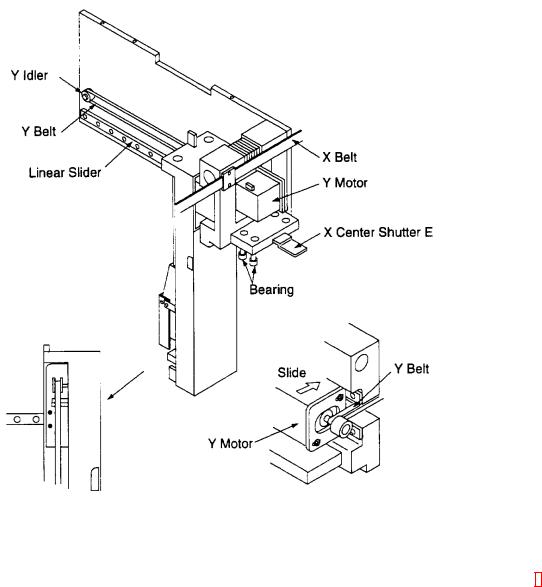
2.7X-Y DRIVE UNIT (X-AXIS MOTOR ASSEMBLY/DRIVE-AXIS ARM ASSEMBLY)
2.7.1Outline
This unit moves the sample probe, which aspirates and dispense plasma and reagent, to the Sample Rack, Reagent Rack, and Reaction Tube Rack; and drives, in X-Y direction, the catcher which moves reaction tubes from the reaction tube rack to the heater section, detector block, and further to dispense/discard hole.
2.7.2Specifications/Functions
(1)X-Direction System
Drive Source: |
Unipolar type stepping motor (1-2 phase excitation, constant current drive) |
Drive transmission: |
Timing belt type |
Resolving power: |
Approx. 0.08 mm/step |
Drive speed: |
Approx. 4500 pps (at high speed in trapezoidal control) |
Sensor: |
For drive unit home position (transmission type) - 1 unit |
(2) Y-Direction System |
|
Drive Source: |
Unipolar type stepping motor (1-2 phase excitation, constant current drive) |
Drive transmission: |
Timing belt type |
Resolving power: |
Approx. 0.08 mm/step |
Drive speed: |
Approx. 4000 pps (at high speed in trapezoidal control) |
Sensor: |
For drive unit home position (transmission type) - 1 unit |
2.7.3Assembly Diagram
CA-500 Series S/M |
2-8 |
Revised December 2001 8 |

2.8Z-AXIS DRIVE UNIT (Z-AXIS BASE ASSEMBLY)
2.8.1Outline
To use the sample probe for aspiration or draining and to move reaction tubes, this unit grips the catcher and drives it in Z direction. The Z-axis base assembly incorporates a mechanism for mixing plasma and reagent in reaction tubes.
2.8.2Specifications/Functions
(1) |
Z-Direction System |
|
|
Drive Source: |
Unipolar type stepping motor (1-2 phase excitation, constant current drive) |
|
Drive transmission: |
Timing belt type |
|
Resolving power: |
Approx. 0.08 mm/step |
|
Drive speed: |
Approx. 3100 pps (at high speed in trapezoidal control) |
|
Sensor: |
For drive unit home position (transmission type) - 1 unit |
(2) |
Stirring Function |
|
|
Power source: |
DC motor (Driving voltage: 1.05 V) |
(3) |
Reaction tube Presence Detection |
|
|
Sensor: |
Detects presence of reaction tubes (modulation-reflection type) - 1 unit |
(4) |
Sample Probe |
|
|
Shape Material: |
ID 0.50 mm/OD 0.85 mm, SUS316 |
|
Heater: |
|
|
Sensor: |
Glass chip thermistor |
|
Overheat protection: |
Thermal fuse 76°C |
2.8.3Assembly Diagram
CA-500 Series S/M |
2-9 |
Revised December 2001 8 |

2.9BAR CODE READER UNIT (ID COMPLETED PARTS)
2.9.1Outline
This unit drives the bar code reader, which reads ID labels affixed on the sampler set on the sample table.
2.9.2Specifications/Functions
(1) |
Drive System |
|
|
Drive Source: |
Unipolar-type stepping motor (2-phase excitation, constant current drive) |
|
Drive Transmission: |
Timing belt type |
|
Resolving Power: |
Approx. mm/step |
|
Drive Speed: |
Approx. pps (at high speed in constant control) |
|
Sensor: |
For drive unit home position (transmission type) - 1 unit |
(2) |
ID Specifications |
|
|
Light Source/Receptor Element: LED/CCD image sensor |
|
|
Read Width: |
80 mm |
|
Scan Cycles: |
500 scans/500 decodes per second |
|
Interface: |
Conforms to RS-232C |
|
Power Source: |
DC 5 V, 300 mA |
|
Corresponding Code: |
CODE39, NW-7, Industrial 2 of 5, CODE 128, etc. |
CA-500 Series S/M |
2-10 |
Revised December 2001 8 |

2.10PUMP UNIT (PRESSURE PUMP/VACUUM PUMP COMPLETED PARTS)
2.10.1Outline
The pump unit comprises the pressure pump that applies positive pressure into the bottle to feed rinse solution from the rinse bottle into the system and the vacuum pump that applies vacuum into the bottle to feed out waste from the system into waste bottle.
2.10.2Specifications/Functions
(1)Pressure Pump Structure:
Pressure: 250 mmHg as adjusted 19
(2)Vacuum Pump Structure:
Vacuum: Approx. 180 mmHg as not adjusted 19
2.10.3Assembly Diagram
CA-500 Series S/M |
2-11 |
Revised February 2004 |
|
|
19 TB200408 |
Loading...