


OPERATOR’S MANUAL
Automated Blood Coagulation Analyzer
CA-50
CHAPTER 1: |
INTRODUCTION |
CHAPTER 2: |
ANALYSIS PREPARATION |
CHAPTER 3: |
SAMPLE ANALYSIS |
CHAPTER 4: DISPLAY OF ANALYSIS RESULTS |
|
CHAPTER 5: |
MAINTENANCE & SUPPLIES REPLACEMENT |
CHAPTER 6: |
QUALITY CONTROL |
CHAPTER 7: |
SETTING STANDARD CURVES |
CHAPTER 8: |
TROUBLESHOOTING |
CHAPTER 9: |
FUNCTIONAL DESCRIPTION |
CHAPTER 10: INSTRUMENT SETUP |
|
APPENDIX A: |
INSTALLATION |
APPENDIX B: TECHNICAL INFORMATION
INDEX
SYSMEX CORPORATION
KOBE, JAPAN
Copyright 1999 - 2001 by SYSMEX CORPORATION |
|
All rights reserved. No part of this Operator’s Manual may be |
Code No. 461-2035-2 |
reproduced in any form or by any means whatsoever without |
PRINTED IN JAPAN |
prior written permission of SYSMEX CORPORATION. |
Date of Last Revision: February 2001 |

•Sysmex is a registered trademark of SYSMEX CORPORATION.
•Dade is a registered trademark of Dade Behring Inc.
•Actin and Ci-Trol are registered trademarks of Dade International Inc.
•Eppendorf is a registered trademark of Eppendorf-Netherler-Hinz GmbH.
•Other trademarks referenced are property of their respective owners.
•It is prohibited to reproduce part or all of the contents of this Manual without permission.
•The display screens shown in this manual may differ slightly from the actual displays.
•As a result of product improvements, details described in this manual may differ slightly from the actual product.
•Patient names and doctor names are entered for information and illustration purposes only, and do not imply real specific persons.
Sysmex CA-50 Operator’s Manual -- Revised July 1999
RECEIVING INSTRUCTIONS
The CA-50 has been thoroughly tested before shipment, and has been packaged carefully to prevent damage from shipping and handling. Reagents and options have also been sent and will arrive accompanying the analyzer. Follow these guidelines when the system arrives:
•Check to see that the arrows on the sides of the packages are pointing up. If the arrows do not point up, record this information on the bill of lading.
•Visually inspect the outside of the package for rips, dents, or possible shipping damage. Document any sign of damage on the bill of lading, regardless of how insignificant it may appear. This is for your protection!
•Notify your service representative that the CA-50 system and its components have arrived.
•Wait for your service representative to unpack the system and open the packages.
•Follow the unpacking and storage instructions provided on the outside of the package. Special requirements such as refrigeration are clearly marked on the outside of the carton and will be included in the unpacking instructions and package inserts.
WARRANTY INFORMATION
All instruments manufactured by Sysmex® are warranted against defective materials or workmanship for a period of one year commencing on the installation date at the customer's required location.
This Warranty does not cover any defect, malfunction, or damage due to:
1. Accident, neglect or willful mistreatment of the product
2. Failure to use, operate, service, or maintain the product in accordance with the applicable Sysmex Operator's Manual
3. Failure to use the appropriate reagents or chemicals specified for the product
Sysmex CA-50 Operator’s Manual -- Revised July 1999 |
I |

ENSURE SAFE OPERATION OF THE INSTRUMENT
Before operating this instrument, carefully read the "Ensure Safe Operation of the Instrument" and OPERATOR’S MANUAL, and strictly follow the instructions given in them.
This manual carries a variety of illustrations to make sure that the product can be used safely and correctly, thus preventing you and others from suffering injuries and damage to property.
The illustrations and meaning are described in the following.
Do understand what they mean before proceeding to the text of the MANUAL.
Meaning of Signs
 WARNING • If this sign is ignored and the instrument is operated incorrectly, there is a potentially hazardous situation which could result in death or serious injury of an operator, or grave property damage.
CAUTION • If this sign is ignored and the instrument is operated incorrectly, there is a potentially hazardous situation which may result in injury of an operator, adverse effect on output, or may cause property damage.
Caution on Diagnosis
CAUTION • This product is a clinical examination instrument for screening. In making clinical judgment based on analysis results, a physician is requested to take clinical examination results and other test results into consideration.
II |
Sysmex CA-50 Operator’s Manual -- Revised July 1999 |

 WARNING
•In the event the instrument emits abnormal odor or any smoke, turn OFF the power immediately and disconnect the power plug from the wall socket.
If the instrument is used continuously in that state, there is a hazard that fire, electrical shock, or injury may result.
Contact your Sysmex service representative for inspection.
•Take care not to spill blood or reagent, or drop wire staples or paper clips into the instrument.
Those might cause short circuit or smoke emission. If such trouble should occur, turn OFF the power immediately and disconnect the power plug from the wall socket. Then contact your Sysmex service representative for inspection.
•Do not touch the electrical circuits inside the cover. Especially if your hands are wet, there is a hazard that electrical shock may result.
•During an analysis, do not open the pipette guide and put in hands or fingers. That could cause injury. When the pipette guide is opened during an analysis, an alarm sounds and the operation stops.
•Always wear rubber gloves when performing maintenance work or inspection. Use specified tools and parts.
After work is over, wash your hands with disinfectant.
There is a possibility that those areas of your hands which came in contact with blood could suffer infection.
•Be careful when handling samples.
Always wear rubber gloves; otherwise infection by bacteria could result. If sample splash happened to enter your eye or a cut, wash it off with plenty of water, and immediately see a physician.
When Handling Reagent
•If a reagent happens to enter your eye, wash it off immediately using plenty of water, and take medical treatment at once.
•If you should swallow it inadvertently, call for a physician immediately, drink plenty of water, and throw up.
•If it happens to adhere to your hands or skins, wash it off using plenty of water.
•When discarding used reaction tubes and instrument consumables, take proper
disposing steps as medical, infectious, and industrial wastes.
If they are contaminated with blood, infection of bacteria may result.
•Do not modify the instrument. Its modification is prohibited by Pharmaceutical Affairs Law.
Sysmex CA-50 Operator’s Manual -- Revised July 1999 |
III |

 WARNING
Power Supply, Connection, and Grounding
•Never put the power plug in any socket other than the AC 117, 220 or 240 V socket.
Otherwise, fire or electrical shock will result.
•When installing the instrument, be sure to ground it.
Otherwise, fire or electrical shock will result.
Handling Power Supply Cord
•Take care not to damage the power cord, place a heavy device on it, or pull it forcibly.
Otherwise, the wire may break causing fire or electrical shock.
•When connecting the instrument to a peripheral (host computer), be sure to switch OFF the power beforehand.
Otherwise, electrical shock or instrument failure may result.
I V |
Sysmex CA-50 Operator’s Manual -- Revised July 1999 |

 CAUTION
Use of Reagents
•After unpacking, be sure not to allow dust, dirt, or bacteria to come in touch with the reagent.
• Do not |
use reagents which have expired. |
• Handle |
a reagent gently to prevent formation of bubbles. |
•Take care not to spill a reagent. If it spills, wipe it off immediately using a wet cloth or the like.
•Follow other instructions described on the Package Insert in each reagent.
Use of Instrument
•When performing maintenance work or inspection, use specified tools and parts. Do not use substitute parts, or modify the instrument. It is hazardous.
•Those who have no or only limited experience in using instrument are recommended to have guidance or assistance of those with sufficient experience.
•If the instrument has developed a trouble by any chance, a person in charge of it should take steps within the range specified in the OPERATOR’S MANUAL. As to troubles other than mentioned, contact your Sysmex service representative for assistance or service.
•Unpacking, installation, and confirmation of initial setup must be done by your Sysmex service representative.
Environment for Use
•Install the instrument in a place which is not subject to water splash.
•Install the instrument in a place which is not subject to adverse effects of high
temperature, high humidity, dust, direct sunlight, strong lighting, etc.
•Do not give the instrument a strong vibration or impact.
•Do not install the instrument near a chemical storage or a place where a gas is generated.
Recommended Pipette and Pipette Chip
• We recommended that you use the following pipettes and pipette chips to add
plasma and |
dispense/add reagents. |
|
• |
Pipette: |
Eppendorf reference 4910 (50 - 200 L) |
• |
Pipette |
Eppendorf 300 L chip |
For details on the usage of the pipette and pipette chip, refer to the instruction manuals attached to them.
CA-50 |
-- |
July 1999 |
V |
SysmexCA-50 Operator’sManual-- RevisedDecember 2000 |
|||
INTRODUCTION
Thank you for purchasing the Sysmex® Automated Blood Coagulation Analyzer CA-50. Carefully read the OPERATOR’S MANUAL for correct use of the unit.
Keep this MANUAL in good condition after reading. It will continue to be of your help in finding specific information about this instrument.
V I |
Sysmex CA-50 Operator’s Manual -- Revised July 1999 |
CONTENTS OF THIS MANUAL
To make full use of the functions of this instrument, thoroughly read this manual and use the instrument as directed. The Operator’s Manual is made up of the ten chapters and appendices listed below.
Chapter 1: |
Introduction |
Provides an overview of the instrument, explaining its |
|
|
equipment, operating procedures, and messages as |
|
|
well as points to be careful about during installation. |
|
|
|
Chapter 2: |
Analysis Preparation |
Explains how to prepare the instrument, reagents, and |
|
|
samples before performing analyses. |
|
|
|
Chapter 3: |
Sample Analysis |
Describes how to analyze samples and explains |
|
|
registration procedures for sample ID numbers and |
|
|
analysis parameters. |
|
|
|
Chapter 4: |
Display of Analysis Results |
Explains the screen displays and the processing of |
|
|
external output. |
|
|
|
Chapter 5: |
Maintenance & Supplies |
Explains the periodic maintenance procedures and how |
|
Replacement |
to replace reagent and other supplies. |
|
|
|
Chapter 6: |
Quality Control |
Explains how to perform quality control analyses and |
|
|
how to print and store quality control data. |
|
|
|
Chapter 7: |
Setting Standard Curves |
Explains how to prepare standard curves. |
|
|
|
Chapter 8: |
Troubleshooting |
Explains the error messages and how to troubleshoot. |
|
|
|
Chapter 9: |
Functional Description |
Explains the coagulation detection principles. Also lists |
|
|
the names and functions of the each parts. |
|
|
|
Chapter 10: |
Instrument Setup |
Explains how to preset the instrument's various |
|
|
settings, such as the data measure settings (including |
|
|
limits that indicate abnormal data) and the test protocol |
|
|
settings. |
|
|
|
Appendix A: |
Installation |
Explains how to install the CA-50. |
|
|
|
Appendix B: |
Technical Information |
Includes data output format for host computer and other |
|
|
reference materials. |
|
|
|
Sysmex CA-50 Operator’s Manual -- Revised July 1999 |
VII |

PREMISES FOR SIGNS
Meaning of Signs
 WARNING • If this sign is ignored and the instrument is operated incorrectly, there is a potentially hazardous situation which could result in death or serious injury of an operator, or grave property damage.
CAUTION • If this sign is ignored and the instrument is operated incorrectly, there is a potentially hazardous situation which may result in injury of an operator, adverse effect on output, or may cause property damage.
CAUTION: • Indicates what we would like you to know to maintain instrument performance and prevent its damage.
NOTE: • Indicates information which will come handy in operating the instrument.
Document Conventions
In explaining operation, this manual uses the conventions as shown below.
•The keys on the panel keyboard are expressed within square brackets. For example: [Start], [Print], [ ]
]
•The display on LCD appears within quotation marks. For example: "PT", "QC"
NOTE: • LCD and printing described in this manual may differ from those in practice.
•As a result of product improvements, details described in this manual may differ slightly from the actual product.
VIII |
Sysmex CA-50 Operator’s Manual -- Revised July 1999 |
CA-50 OPERATOR’S MANUAL
TABLE OF CONTENTS
CHAPTER 1: INTRODUCTION |
|
||
1. |
INTRODUCTION ......................................................................................... |
1-1 |
|
2. |
INSTRUMENT OVERVIEW ....................................................................... |
1-2 |
|
3. |
OUTLINE OF OPERATION ........................................................................ |
1-3 |
|
4. |
ANALYSIS PARAMETERS AND CALCULATION PARAMETERS...... |
1-4 |
|
5. |
LCD SCREEN AND INPUT KEYS ............................................................. |
1-6 |
|
|
5.1 |
LCD Screen ......................................................................................... |
1-6 |
|
5.2 |
Input Keys............................................................................................ |
1-7 |
6. |
PASSWORDS ............................................................................................... |
1-8 |
|
7. |
ALARMS ................................................................................................... |
1-8 |
|
8. |
DETECTOR LED.......................................................................................... |
1-9 |
|
9. |
PACKAGING................................................................................................ |
1-9 |
|
10. |
INSTALLATION ENVIRONMENT.......................................................... |
1-10 |
|
|
10.1 |
Installation and Relocation ................................................................ |
1-10 |
|
10.2 |
Grounding.......................................................................................... |
1-10 |
|
10.3 |
Installation Space............................................................................... |
1-11 |
|
10.4 |
Installation Environment ................................................................... |
1-11 |
11. |
INSTRUMENT SPECIFICATIONS........................................................... |
1-12 |
|
12. |
MENU TREE............................................................................................... |
1-16 |
|
13. |
MAIN MENU.............................................................................................. |
1-17 |
|
CHAPTER 2: ANALYSIS PREPARATION |
|
||
1. |
INTRODUCTION ......................................................................................... |
2-1 |
|
2. |
BEFORE TURNING ON THE POWER ...................................................... |
2-2 |
|
3. |
TURNING ON THE POWER....................................................................... |
2-2 |
|
4. |
REAGENT PREPARATION ........................................................................ |
2-4 |
|
|
4.1 |
Preparing the Reagents ........................................................................ |
2-4 |
|
4.2 |
Setting the Reaction Tubes and Reagents............................................ |
2-5 |
5. |
CHECKING THE STANDARD CURVES .................................................. |
2-6 |
|
6. |
QUALITY CONTROL.................................................................................. |
2-7 |
|
7. |
SAMPLE PREPARATION........................................................................... |
2-8 |
|
CHAPTER 3: SAMPLE ANALYSIS |
|
||
1. |
INTRODUCTION ......................................................................................... |
3-1 |
|
2. |
WORK LIST.................................................................................................. |
3-2 |
|
|
2.1 |
Selecting the Analysis Parameter ........................................................ |
3-2 |
|
2.2 |
Registering the Sample ID Number..................................................... |
3-4 |
3. |
SAMPLE ANALYSIS................................................................................... |
3-6 |
|
|
3.1 |
Start of Analysis .................................................................................. |
3-7 |
|
3.2 |
Adding the Reagents............................................................................ |
3-8 |
|
3.3 |
Registering and Analyzing the Next Sample..................................... |
3-11 |
4. |
SHUTDOWN .............................................................................................. |
3-12 |
|
Sysmexex CA--50Operator’sManual--RevisedJulyDecember1999 2000 |
i |

CHAPTER 4: DISPLAY OF ANALYSIS RESULTS |
|
||
1. |
INTRODUCTION................................................................... |
4-1 |
|
2. |
DISPLAYING AND PRINTING OUT ANALYSIS RESULTS ............. |
4-1 |
|
|
2.1 |
Displaying the Analysis Results ........................................... |
4-1 |
|
2.2 |
Printing Out the Analysis Results.......................................... |
4-3 |
3. |
DISPLAYING DETAILED ANALYSIS RESULTS .......................... |
4-5 |
|
4. |
OUTPUTTING ANALYSIS RESULTS ......................................... |
4-7 |
|
CHAPTER 5: MAINTENANCE & SUPPLIES REPLACEMENT |
|
||
1. |
INTRODUCTION................................................................... |
5-1 |
|
2. |
CA-50 MAINTENANCE CHECKLIST ......................................... |
5-2 |
|
3. |
DAILY MAINTENANCE AND INSPECTION ................................ |
5-3 |
|
|
3.1 |
Cleaning the Reaction Tube Holder, Incubator, and Pipette guide .... |
5-3 |
4. |
WEEKLY MAINTENANCE AND INSPECTION ............................ |
5-4 |
|
|
4.1 |
Cleaning the Instrument ..................................................... |
5-4 |
|
4.2 |
Cleaning by Blower.......................................................... |
5-5 |
5. |
REPLACING SUPPLIES .......................................................... |
5-6 |
|
|
5.1 |
Replacing Fuses .............................................................. |
5-6 |
|
5.2 |
Replacing Printer Paper ..................................................... |
5-7 |
|
5.3 |
Supply Parts List ............................................................. |
5-8 |
CHAPTER 6: QUALITY CONTROL |
|
||
1. |
INTRODUCTION................................................................... |
6-1 |
|
|
1.1 |
Quality Control File.......................................................... |
6-1 |
|
1.2 |
Quality Control Analysis.................................................... |
6-1 |
|
1.3 |
QC Error Check .............................................................. |
6-2 |
2. |
QUALITY CONTROL MENU.................................................... |
6-3 |
|
|
2.1 |
Displaying the QC Chart .................................................... |
6-3 |
3. |
SELECTING THE QUALITY CONTROL FILE .............................. |
6-4 |
|
|
3.1 |
Selecting the Quality Control Parameter.................................. |
6-4 |
|
3.2 |
Selecting the Quality Control File ......................................... |
6-5 |
4. |
PRINTING OUT THE QC CHART .............................................. |
6-6 |
|
5. |
DELETING THE QUALITY CONTROL DATA .............................. |
6-7 |
|
|
5.1 |
Deleting the Data............................................................. |
6-7 |
|
5.2 |
Deleting the File.............................................................. |
6-8 |
6. |
QUALITY CONTROL SETTINGS .............................................. |
6-9 |
|
ii |
SysmexSysmexCA-50CAOperator’s-50 Operator’sManualManual-- Revised-- RevisedDecemberJuly 1999 |

CHAPTER 7: SETTING STANDARD CURVES |
|
||
1. |
INTRODUCTION ......................................................................................... |
7-1 |
|
2. |
OBTAINING DATA FOR STANDARD CURVE....................................... |
7-1 |
|
3. |
STANDARD CURVE MENU ...................................................................... |
7-4 |
|
4. |
PREPARING THE STANDARD CURVE................................................... |
7-6 |
|
|
4.1 |
Selecting the Analysis Parameter ........................................................ |
7-6 |
|
4.2 |
Inputting the Standard Curve Data ...................................................... |
7-7 |
5. |
PRINTING OUT THE STANDARD CURVE ........................................... |
7-10 |
|
6. |
SETTING THE CALCULATION PARAMETERS................................... |
7-11 |
|
|
6.1 |
Calculation Parameter Setting Menu................................................. |
7-11 |
|
6.2 |
Setting the Activity Percent and Concentration................................. |
7-12 |
|
6.3 |
Setting the Ratio ................................................................................ |
7-14 |
|
6.4 |
Setting the INR .................................................................................. |
7-15 |
|
6.5 |
Setting the DFbg................................................................................ |
7-16 |
|
6.6 |
Printing Out the Calculation Parameter Settings............................... |
7-17 |
7. |
DELETING THE STANDARD CURVE DATA ....................................... |
7-18 |
|
CHAPTER 8: TROUBLESHOOTING |
|
||
1. |
INTRODUCTION ......................................................................................... |
8-1 |
|
2. |
WHEN YOU SUSPECT AN ERROR .......................................................... |
8-1 |
|
3. |
TROUBLESHOOTING BY ERROR MESSAGE........................................ |
8-2 |
|
|
3.1 |
Troubleshooting Guide ........................................................................ |
8-2 |
|
3.2 |
Instrument Errors and Corrective Actions........................................... |
8-3 |
|
3.3 |
Analysis Data Errors and Corrective Actions...................................... |
8-5 |
4. |
INSTRUMENT CHECK............................................................................... |
8-8 |
|
|
4.1 |
Test Program Menu ............................................................................. |
8-8 |
|
4.2 |
Display of Temperatures...................................................................... |
8-9 |
|
4.3 |
Sensor Test......................................................................................... |
8-10 |
|
4.4 |
Key Entry Test................................................................................... |
8-11 |
|
4.5 |
Built-in Printer Test ........................................................................... |
8-11 |
|
4.6 |
Communication Test.......................................................................... |
8-12 |
|
4.7 |
LCD Screen Test................................................................................ |
8-12 |
CHAPTER 9: FUNCTIONAL DESCRIPTION |
|
||
1. |
INTRODUCTION ......................................................................................... |
9-1 |
|
2. |
DETECTION PRINCIPLES FOR COAGULATION METHOD ................ |
9-2 |
|
|
2.1 |
Optical Detection Method (Scattered Light Detection Method) ......... |
9-2 |
|
2.2 |
Blood Coagulation and Scattered Light Intensity................................ |
9-3 |
|
2.3 |
Coagulation Point Detection Method |
|
|
|
(Percentage Detection Method) .......................................................... |
9-4 |
|
2.4 |
Standard Curve for Coagulation Method............................................. |
9-5 |
|
2.5 |
Calculation of PT Ratio and INR Value.............................................. |
9-5 |
|
2.6 |
Analysis Flow ...................................................................................... |
9-6 |
3. |
ANALYSIS MECHANISM ........................................................................ |
9-10 |
|
4. |
INSTRUMENT COMPONENTS AND FUNCTIONS .............................. |
9-11 |
|
|
4.1 |
Front, Top, and Right Side ................................................................ |
9-11 |
|
4.2 |
Rear .................................................................................................. |
9-13 |
|
4.3 |
Bottom ............................................................................................... |
9-14 |
Sysmexex CA--50Operator’sManual--RevisedJulyDecember1999 2000 |
iii |

CHAPTER 10: INSTRUMENT SETUP |
|
||
1. |
INTRODUCTION................................................................. |
10-1 |
|
2. |
SETTING MENU ................................................................. |
10-2 |
|
3. |
MEASURE SETTINGS .......................................................... |
10-3 |
|
|
3.1 |
Measure Setting Menu..................................................... |
10-3 |
|
3.2 |
Test Protocol Settings ..................................................... |
10-4 |
|
3.3 |
Data Check Parameter & Mark Limit Settings......................... |
10-9 |
|
3.4 |
Report Limit Settings ..................................................... |
10-13 |
|
3.5 |
Replication Difference Limit Settings.................................. |
10-17 |
|
3.6 |
Measure Mode & Sample Incubation Ready Check Settings ....... |
10-20 |
|
3.7 |
Conversion Settings....................................................... |
10-23 |
4. |
I/O SETTINGS ................................................................... |
10-26 |
|
|
4.1 |
I/O Setting Menu .......................................................... |
10-26 |
|
4.2 |
Built-In Printer Settings .................................................. |
10-26 |
|
4.3 |
Host Computer Settings .................................................. |
10-28 |
|
4.4 |
Printing Out I/O Settings ................................................. |
10-31 |
5. |
SYSTEM SETTINGS............................................................ |
10-32 |
|
|
5.1 |
System Setting Menu ..................................................... |
10-32 |
|
5.2 |
Date Settings ............................................................... |
10-32 |
|
5.3 |
Time Settings .............................................................. |
10-33 |
|
5.4 |
Password Settings ......................................................... |
10-34 |
6. |
PRINTING OUT ALL SETTINGS ............................................ |
10-36 |
|
APPENDIX A: INSTALLATION |
|
||
1. |
INTRODUCTION.................................................................. |
A-1 |
|
2. |
CHECK BEFORE INSTALLATION ........................................... |
A-1 |
|
3. |
INSTALLATION SPACE ........................................................ |
A-2 |
|
4.CHANGING THE INSTALLATION DIRECTION OF PIPETTE
|
GUIDE ............................................................................... |
A-3 |
|
5. |
INSTALLING THE FILTER ..................................................... |
A-5 |
|
6. |
CONNECTING THE POWER CORD AND CONNECTION CORD ..... |
A-5 |
|
|
6.1 |
Connecting the Power Cord ............................................... |
A-5 |
|
6.2 |
Connecting the Connection Cord ......................................... |
A-7 |
7. |
ADJUSTING THE LCD BRIGHTNESS ....................................... |
A-8 |
|
8. |
SETTING A PRINTER PAPER.................................................. |
A-9 |
|
APPENDIX B: TECHNICAL INFORMATION |
|
||
1. |
OUTPUT FORMAT FOR HOST COMPUTER ............................... |
B-1 |
|
|
1.1 |
Hardware ..................................................................... |
B-1 |
|
1.2 |
Software ...................................................................... |
B-2 |
|
1.3 |
Text Format .................................................................. |
B-3 |
2. |
FACTORY DEFAULT SETTINGS ............................................. |
B-7 |
|
|
2.1 |
QC Parameters and Factory Default Settings ........................... |
B-7 |
|
2.2 |
Standard Curve Data and Factory Default Settings..................... |
B-8 |
|
2.3 |
Standard Curve Calculation Parameters and |
|
|
|
Factory Default Settings ................................................... |
B-11 |
|
2.4 |
Instrument Setting Parameters and Factory Default Settings ........ |
B-12 |
INDEX
iv |
Sysmex CA-50 Operator’s Manual -- Revised July 1999 |

CHAPTER 1 |
INTRODUCTION |
|
|
1. |
INTRODUCTION ................................................................................ |
1-1 |
|
2. |
INSTRUMENT OVERVIEW ................................................................. . |
.1-2 |
|
3. |
OUTLINE OF OPERATION ................................................................. . . |
.1-3 |
|
4. |
ANALYSIS PARAMETERS AND CALCULATION PARAMETERS.................... |
1-4 |
|
5. |
LCD SCREEN AND INPUT KEYS ........................................................... |
1-6 |
|
|
5.1 |
LCD Screen ................................................................................. |
1-6 |
|
5.2 |
Input Keys .................................................................................. |
1-7 |
6. |
PASSWORDS..................................................................................... |
1-8 |
|
7. |
ALARMS........................................................................................... |
1-8 |
|
8. |
DETECTOR LED ................................................................................. |
1-9 |
|
9. |
PACKAGING..................................................................................... |
1-9 |
|
10. |
INSTALLATION ENVIRONMENT ......................................................... |
1-10 |
|
|
10.1 |
Installation and Relocation .............................................................. |
1-10 |
|
10.2 |
Grounding................................................................................. |
1-10 |
|
10.3 |
Installation Space......................................................................... |
1-11 |
|
10.4 |
Installation Environment................................................................. |
1-11 |
11. |
INSTRUMENT SPECIFICATIONS......................................................... |
1-12 |
|
12. |
MENU TREE.................................................................................... |
1-16 |
|
13. |
MAIN MENU ................................................................................... |
1-17 |
|
Sysmex CA-50 Operator’s Manual -- Revised December 2000

INTRODUCTION
1 . INTRODUCTION
The Sysmex® CA-50 is an automated blood coagulation analyzer For In Vitro Diagnostic Use to perform blood coagulation tests in clinical laboratories.
Chapter 1 provides an overview of the instrument and analysis procedures that should be read before the CA-50 is used in a daily routine.
The major elements of Chapter 1 are listed below.
Instrument Overview
Provides an overview of the CA-50’s functions.
Analysis Procedure Overview
Provides an overview of the analysis procedure, LCD screen display, and key operation.
Installation Precautions
Explains matters that require confirmation before installing the instrument, such as the installation space, required equipment, and environmental conditions.
Instrument Specifications
Provides the instrument specifications.
Menu Tree
Shows a menu tree of the CA-50.
Sysmex CA-50 Operator’s Manual -- Revised December 2000 |
1-1 |
INTRODUCTION
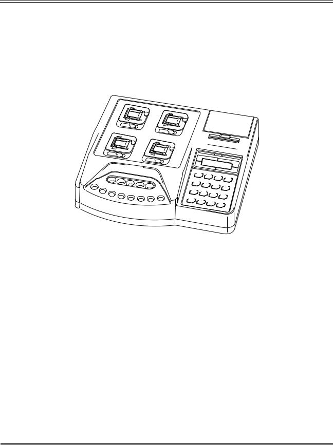
2 . INSTRUMENT OVERVIEW
The CA-50 is an automated blood coagulation analyzer that can quickly analyze samples with a high degree of accuracy. The CA-50 can analyze samples using a Coagulation Method; and the analyzed data can be displayed on its LCD screen and printed by the built-in printer. The CA-50 also has some supplemental functions including quality control.
Figure 1-1: Overview of CA-50
1-2 |
Sysmex CA-50 Operator’s Manual -- Revised December 2000 |

INTRODUCTION
3 . OUTLINE OF OPERATION
The CA-50 performs an analysis by the following procedure.
Table 1-1: CA-50 Analysis Procedure
Check before turning ON power
Power ON
Self-check
Ready
Preparation for analysis
Work List
Press [START] key
Execution of sample incubation
Addition of reagents
Execution of analysis
Discard used reaction tubes
Ready
Power OFF
Operation after analysis completion
: Indicates actions performed by the operator.
Ready : Indicates that the instrument is in the ready status. At this time, the detector LED of each channel will light up in green indicating that you can perform operations such as analysis and settings.
Sysmex CA-50 Operator’s Manual -- Revised December 2000 |
1-3 |

INTRODUCTION
4 . ANALYSIS PARAMETERS AND CALCULATION PARAMETERS
The CA-50 can analyze and calculate the parameters shown below. Additional analysis and calculation parameters can be registered as well.
The following list shows the analysis and calculation parameters that can be analyzed by the CA50.
Table 1-2: CA-50 Analysis Parameters and Calculation Parameters
M e t h o d |
Analysis parameter |
Calculation parameter |
Coagulation |
Prothrombin Time (PT) |
Prothrombin Activity Percent |
Method |
Activated Partial Thromboplastin Time |
Prothrombin Ratio |
|
(APTT) |
INR |
|
Fibrinogen (Fbg) |
Derived Fbg |
|
Thrombotest (TTO) |
Fibrinogen Concentration |
|
Normotest (NT) |
Thrombotest Activity Percent |
|
Thrombin Time (TT) |
Normotest Activity Percent |
|
Extrinsic Factor Deficiency Assay |
Factor II Activity Percent |
|
(II, V, VII, X) |
Factor V Activity Percent |
|
Intrinsic Factor Deficiency Assay |
Factor VII Activity Percent |
|
(VIII, IX, XI, XII) |
Factor VIII Activity Percent |
|
|
|
|
|
Factor IX Activity Percent |
|
|
Factor X Activity Percent |
|
|
Factor XI Activity Percent |
|
|
Factor XII Activity Percent |
CAUTION • If you analyze with a wrong reagent, correct analysis results will not be obtained.
NOTE: • You can set up to 3 types of calculation parameters each for an analysis parameter.
1-4 |
Sysmex CA-50 Operator’s Manual -- Revised December 2000 |

INTRODUCTION
CAUTION Interpretation of APTT Abnormal Early Reaction.
• APTT results less than or equal to 20.0 seconds, APTT results with NC (No Coagulation), SC (Slight Coagulation) or CCE (Coag. Curve Error) error messages, or abnormally short APTT results may be caused by an abnormal early reaction.
APTT results with an abnormal early reaction can be identified in the analysis data.
• If an APTT result less than or equal to 20.0 seconds is obtained, the following steps should be taken:
1. Verify sample and reagent integrity along with maintenance procedures. 2. Print out the Analysis data.
See Chapter 4, Section 4: OUTPUTTING ANALYSIS RESULT and Chapter 10, Section 4.2: Built-In Printer Settings.
Note that the stored analysis results will be deleted, when you start a next analysis on the same channel or you turn OFF the power or so on.
3. Observe time in the “2%” position.
4. If that time is equal to or less than 15 seconds, then an abnormal early reaction may have occurred.
5. Re-analyze the sample.
6. If result is the same, it should not be reported.
7. Review the previous patient history to determine acceptability of patient results. Results of the other parameters considered, then make overall evaluation.
8. Follow your laboratory's alternate protocol.
• An error code may or may not be associated with this result.
• An abnormal early reaction rarely occurs.
• The CA-50 should be set up so that any APTT results of less than or equal to 20.0 seconds will have a message of <20.1 seconds on the printout.
• To set up this function see Chapter 10, Section 3.4: Report Limit Settings and enter 20.1 for the APTT lower limit.
• Remember to change the Built-in Printer Settings back to “List” after review of the analysis data.
Sysmex CA-50 Operator’s Manual -- Revised December 2000 |
1-5 |
INTRODUCTION
5 . LCD SCREEN AND INPUT KEYS
5 . 1 LCD Screen
The instrument’s status, analysis results, and all other information are displayed on the CA-50’s LCD screen. The screen is capable of displaying 16 characters by 2 lines maximum.
Display position of the each analysis channel on the screen
CH3 CH4
CH1 CH2
Figure 1-2: Display position of the each analysis channel on the screen
On the Analysis screen, the LCD screen is split into four parts to show the data of respective channels from 1 to 4.
Analysis parameters are abbreviated into two characters as shown below:
• |
PT: PT |
• |
F5: Factor V |
• |
AP: APTT |
• |
F7: Factor VII |
• |
Fg: Fbg |
• |
F8: Factor VIII |
• |
TO: TTO |
• |
F9: Factor IX |
• |
NT: NT |
• |
10: Factor X |
• |
TT: TT |
• |
11: Factor XI |
• |
F2: Factor II |
• |
12: Factor XII |
Settings Screen
ID No. Entry
Select CH(1-4)?1
Figure 1-3: Example of Settings Screen
On the Settings screen, parameters to be set or selected are displayed on the upper and lower lines.
1-6 |
Sysmex CA-50 Operator’s Manual -- Revised December 2000 |
INTRODUCTION
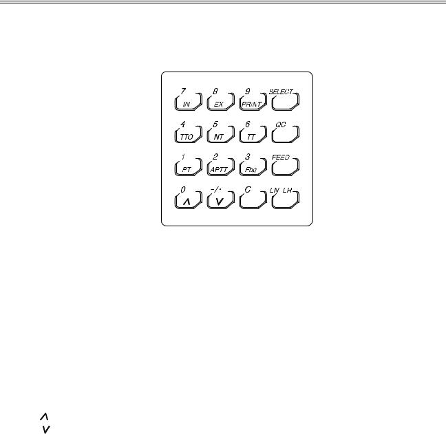
5 . 2 Input Keys
By using the input keys, you can perform each setting such as entering numerals and selecting various parameters.
|
|
|
|
Figure 1-4: Input Keys |
|
|
|
|
|
|
Table 1-3: Operation of Input Keys |
|
|
|
|
|
|
|
|
|
|
|
|
Key |
Operation |
|
|
|
|
|
1/PT |
Press to input the number "1" or select "PT". |
|
|
|
|
|
2/APTT |
Press to input the number "2" or select "APTT". |
|
|
|
|
|
3/Fbg |
Press to input the number "3" or select "Fbg". |
|
|
|
|
|
4/TTO |
Press to input the number "4" or select "TTO". |
|
|
|
|
|
5/NT |
Press to input the number "5" or select "NT". |
|
|
|
|
|
6/TT |
Press to input the number "6" or select "TT". |
|
|
|
|
|
7/IN |
Press to input the number "7" or select "intrinsic factor". |
|
|
|
|
|
8/EX |
Press to input the number "8" or select "extrinsic factor". |
|
|
|
|
|
9/PRINT |
Press to input the number "9" or print a menu. |
|
|
|
|
|
0/ |
Press to input the number "0", scroll a menu up, or switch to the previous data. |
|
|
|
|
|
-/./ |
Press to input a hyphen or a decimal point, scroll a menu down, or switch to the next |
|
|
|
|
|
|
data. |
|
|
|
|
|
C |
Press to clear inputted data or stop an error beep. |
|
|
|
|
|
SELECT |
Press to switch between Menu and Ready, cancel updated data (when confirmed), or |
|
|
|
|
|
|
return to the previous screen. |
|
|
|
|
|
QC |
Press to input "QC" (when inputting an ID number). |
|
|
|
|
|
FEED |
Press to feed paper. |
|
|
|
|
|
ENTER |
Press to set inputted data or execute updated data (when confirmed). |
|
|
|
|
|
|
|
|
|
|
|
|
CAUTION: |
• When a key has two or more functions, the function will be changed over |
|
|
|
|
|
|
depending on the situation when the key is pressed. |
|
|
|
|
|
|
|
|
|
|
|
|
|
|
|
|
|
|
|
|
|
|
|
|
|
|
|
|
|
|
Sysmex CA-50 Operator’s Manual -- Revised December 2000 |
1-7 |

INTRODUCTION
6 . PASSWORDS
Important programs are protected by a password so that the programs can be executed under the control of a supervisor.
When a menu that is protected by a password is to be executed, a Password Entry window will appear. To execute the menu, enter the preset password and press the [Enter] key.
For details on how to set the password, see Chapter 10, Section 5.4: Password Settings.
7 . ALARMS
The CA-50 makes three types of alarm sounds.
1.Key Entry
A short beep will sound each time an input key is pressed.
2.Reagent addition timing
Two short beeps followed by a long beep will sound to let you know the timing of adding reagents.
The time allowed for reagent addition is preset at 10 seconds as default; 5 seconds before and after the time of addition. If you wish to change the allowed time, see Chapter 10, Section 3.2: Test Protocol Settings.
Table 1-4: Reagent Addition Timing Alarm
|
Reagent |
|
5 seconds |
|
• • • |
Reagent |
• • • |
Reagent |
|
|
addition allowed |
|
before |
|
|
addition |
|
|
addition |
|
time (start) |
|
|
|
|
|
|
|
allowed time |
|
|
|
|
|
|
|
|
|
(end) |
|
Two short |
No sound |
A short |
A short beep |
A long beep |
A short beep |
A long beep |
||
|
beeps |
|
beep |
|
|
|
|
|
|
|
|
|
|
One beep |
For 0.5 |
One beep |
An error beep |
||
|
|
|
|
per second |
seconds |
per second |
|
||
|
|
|
|
|
|
|
|
|
|
|
|
|
|
|
|
|
|
|
|
|
|
|
|
|
|
|
|
|
|
Allowed time for reagent addition
3.Error
A long beep will sound when an error occurs on the instrument. The beep will continue to sound until the [C] key is pressed.
1-8 |
Sysmex CA-50 Operator’s Manual -- Revised December 2000 |

INTRODUCTION
8 . DETECTOR LED
The detector LED of each channel indicates the status as shown in the table below.
Table 1-5: Operation of Detector LED
During |
Ready |
During |
Reagent |
During photo |
Ready |
warming-up |
|
incubation |
addition timing |
detection |
|
|
|
|
|
|
|
Turns off |
Lights up in |
Blinks in red |
Blinks in green |
Lights up in red |
Lights up in |
|
green |
|
|
|
green |
9 . PACKAGING
The CA-50 is thoroughly checked before it is shipped from the factory, and is carefully packaged to withstand shocks during shipment.
After the CA-50 has been delivered, check the packaging. Make sure that the instrument is free of exterior damage.
Your Sysmex service representative will unpack and install the instrument after delivery and will also set the initial settings.
Sysmex CA-50 Operator’s Manual -- Revised December 2000 |
1-9 |

INTRODUCTION
1 0 . INSTALLATION ENVIRONMENT
10 . 1 Installation and Relocation
The CA-50 is installed by your Sysmex Service representative. In case relocation becomes necessary after installation, see Appendix A: INSTALLATION to install the instrument correctly.
WARNING • When relocating the CA-50, be sure to wear rubber gloves. After the relocation, wash your hands with disinfectant solution.
If your hands are contaminated with blood, infection by bacteria or the like can occur.
CAUTION • When relocating the CA-50, hold the instrument securely. If the instrument falls, you can get injured or the instrument can be damaged.
10 . 2 Grounding
The instrument power supply cord uses a 3-prong plug. When the power supply socket is 3- prong (with grounded), simply plug it to the socket.
117 VAC Spec. |
220 VAC Spec. |
240 VAC Spec. |
Figure 1-5: Plugs
WARNING • Make sure to ground the instrument. Inadequate grounding could cause electrical shocks.
NOTE: • The number of power supply sockets required is 1.
1-10 |
Sysmex CA-50 Operator’s Manual -- Revised December 2000 |

INTRODUCTION
10 . 3 Installation Space
To ensure that the instrument fulfills its function, it is important to install it in an appropriate place:
•Select a place that is close to the power supply.
•Secure a place spacious enough for maintenance and service. Giving consideration to heat radiation by the instrument, provide at least 10 cm distance from the wall to the rear panel.
The instrument dimensions are shown below. The power supply cord is 1.8 m long.
Table 1-6: Instrument Dimensions
Width (mm) |
Depth (mm) |
Height (mm) |
Weight (kg) |
|
327 |
302 |
113 |
4.5 |
|
|
327 |
mm |
|
|
|
|
|
|
|
|
|
|
113 |
mm |
|
|
|
|
|
302 |
mm |
|
Figure 1-6: Instrument Dimensions
10. 4 Installation Environment
•Use the instrument at an ambient temperature of 15°C - 35°C (optimum: 23°C).
•Use it at a relative humidity range of 30% - 85%.
•Avoid a place that can become extremely hot or cold.
•Avoid a place that can be exposed to direct sunlight.
•Choose a well-ventilated place.
•Avoid a place close to a wireless telegraph or communication facility where high frequency waves can be generated or radio interference can occur.
•Do not use in dusty areas.
Sysmex CA-50 Operator’s Manual -- Revised December 2000 |
1-11 |

INTRODUCTION
1 1 . INSTRUMENT SPECIFICATIONS
Analysis parameters/Calculation parameters
See Section 4: ANALYSIS PARAMETERS AND CALCULATION PARAMETERS in this chapter.
Simultaneous Random Analysis of 4 Parameters
Random analysis is possible.
Required Sample |
|
L |
Prothrombin Time (PT): |
50 |
|
Activated Partial Thromboplastin Time (APTT): |
50 |
L |
Fibrinogen (Fbg): |
10 |
L |
Thrombotest (TTO): |
20 |
L |
Normotest (NT): |
10 |
L |
Thrombin Time (TT): |
100 |
L |
Extrinsic Factor Deficiency Assay (II, V, VII, X): |
5 |
L |
Intrinsic Factor Deficiency Assay (VIII, IX, XI, XII): |
5 |
L |
Analysis Principles
Coagulation Method
1. Coagulation Reaction Detection Method (Scattered Light Detection Method)
Irradiates red light (660 nm) onto a mixture of blood plasma and reagent and detects the change in turbidity (when the fibrin clots are formed) as the change in scattered light. And measures the coagulation time.
2. |
Coagulation Point Detection Method (Percentage Detection Method) |
|
Calculates the coagulation time as the time required to achieve the amount of scattered light |
|
that is set for the coagulation detection point, using the amount of scattered light that is |
|
present just after the start of detection as 0%, and the amount of scattered light that is |
|
present at the completion of coagulation as 100%. |
Range of Analysis
Fibrinogen Concentration
Can analyze from 50 mg/dL to 450 mg/dL.
Detection Time
Detects within the maximum detection time, and measures the result.
Typical maximum detection time: 100 seconds for PT and Fbg; 190 seconds for others. Maximum detection time: 600 seconds for each parameter
1-12 |
Sysmex CA-50 Operator’s Manual -- Revised December 2000 |

INTRODUCTION
Reproducibility |
|
Prothrombin Time (PT): |
C.V. 2% or less |
Activated Partial Thromboplastin Time (APTT): |
C.V. 2% or less |
Fibrinogen (Fbg): |
C.V. 4% or less |
Thrombotest (TTO): |
C.V. 4% or less |
Normotest (NT): |
C.V. 4% or less |
Thrombin Time (TT): |
C.V. 10% or less |
Extrinsic Factor Deficiency Assay (II, V, VII, X): |
C.V. 5% or less |
Intrinsic Factor Deficiency Assay (VIII, IX, XI, XII): |
C.V. 5% or less |
*The data above are variation coefficients for coagulation times (in seconds) or for the amount of change in activity% taken from 10 analyses of Dade Behring Ci-Trol Level 1 (control plasma), with the reagents below used.
Thromboplastin•C plus
Dade Behring Actin Activated Cephaloplastin Reagent 20 mM Calcium Chloride Solution
Dade Behring Fibrinogen Determination Reagents Owren's Veronal Buffer
CA Series Complex Factor TTO CA Series Complex Factor HPT
Dade Behring Factor-deficient Plasma
Display
Displays characters on a liquid crystal display (LCD).
Printing
Permits graphic printing through a built-in printer. (Printer paper specification: F1-1, width: 58 mm)
External Input/Output
Equipped with an RS-232C serial port (bit serial voltage signal).
Detector
Detector: 4 wells (Scattered light detector)
Incubator
Incubator: 5 wells
Reaction Tube Holder
Reaction tube holder: 8 wells
Temperature Control
Detector: 37°C±0.5°C
Incubator: 37°C±1°C
Applies when room temperature is within 15°C - 35°C.
Time to Reach Temperature Setting
Reaches preset temperature within 30 minutes after power is turned ON (when the room temperature is within the specified range).
Sysmex CA-50 Operator’s Manual -- Revised December 2000 |
1-13 |

INTRODUCTION
Quality Control |
|
|
50 points × 3 files, 14 parameters |
|
|
control (L-J control): |
|
|
|
X |
|
|
||
Standard Curve |
|
|
|
|
6 points, 14 parameters |
|
|
|
|
Power |
|
|
117 VAC±10%, 230 VAC±15% |
|
Rated voltage: |
|
|
||
Frequency: |
|
|
50 Hz or 60 Hz |
|
Power consumption: |
|
|
90 VA or less |
|
Temperature Compensation Required: |
Approx. 307 BTU/h (77 kcal/h) |
|||
Environmental Requirements |
|
|
||
15°C - 35°C |
|
|
|
|
Dimensions/Weight |
|
× 302 (D) × 113 (H) mm; approx. 4.5 kg |
||
Main Unit: |
327 (W) |
|||
1-14 |
Sysmex CA-50 Operator’s Manual -- Revised December 2000 |

INTRODUCTION
CAUTION Interpretation of APTT Abnormal Early Reaction.
• APTT results less than or equal to 20.0 seconds, APTT results with NC (No Coagulation), SC (Slight Coagulation) or CCE (Coag. Curve Error) error messages, or abnormally short APTT results may be caused by an abnormal early reaction.
APTT results with an abnormal early reaction can be identified in the analysis data.
• If an APTT result less than or equal to 20.0 seconds is obtained, the following steps should be taken:
1. Verify sample and reagent integrity along with maintenance procedures. 2. Print out the Analysis data.
See Chapter 4, Section 4: OUTPUTTING ANALYSIS RESULT and Chapter 10, Section 4.2: Built-In Printer Settings.
Note that the stored analysis results will be deleted, when you start a next analysis on the same channel or you turn OFF the power or so on.
3. Observe time in the “2%” position.
4. If that time is equal to or less than 15 seconds, then an abnormal early reaction may have occurred.
5. Re-analyze the sample.
6. If result is the same, it should not be reported.
7. Review the previous patient history to determine acceptability of patient results. Results of the other parameters considered, then make overall evaluation.
8. Follow your laboratory's alternate protocol.
• An error code may or may not be associated with this result.
• An abnormal early reaction rarely occurs.
• The CA-50 should be set up so that any APTT results of less than or equal to 20.0 seconds will have a message of <20.1 seconds on the printout.
• To set up this function see Chapter 10, Section 3.4: Report Limit Settings and enter 20.1 for the APTT lower limit.
• Remember to change the Built-in Printer Settings back to “List” after review of the analysis data.
Sysmex CA-50 Operator’s Manual -- Revised December 2000 |
1-15 |
 Loading...