Symmons S-3500 Service Manual


 Dia™
Dia™
Tub-Shower Systems S-3500, S-3501, S-3502 Series
Installation and Service Instructions
Model Number Series
S-3502.......... Tub-Shower System S-3502-X....... Valve includes stops S-3502-TRM. Trim only
S-3501.......... Shower System S-3501-X....... Valve includes stops S-3501-TRM. Trim only
S-3500.......... Shower Valve System S-3500-X....... Valve includes stops S-3500-TRM. Trim only
S-3500TS...... Tub-Shower Valve Sys. S-3500TS-X.. Valve includes stops
Need Help?
Symmons customer service: (800) 796-6667, (781) 848-2250
customerservice@symmons.com Mon - Fri 7:30 am - 7:00 pm EST
www.symmons.com/service
•Technical help
•Product information
•Warranty policy
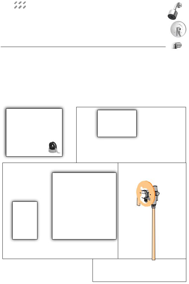
Visual Guide Dia Tub-Shower Systems, S-3500, S-3501, S-3502 Series
Tools & Materials |
Arm and ange |
|
300S |
3/32"
1 |
2 |
3 |
4 |
Model Series
S-3500 S-3502 S-3500-X S-3502-X S-3500-TRM S-3502-TRM
S-3501 S-3500TS S-3501-X S-3500TS-X S-3501-TRM
|
Showerhead |
|
352SH |
|
Mounting |
|
plate, T-177 |
Screwless escutcheon kit |
Temp Limit |
RTS-011, brass |
stop screw |
RTS-012, plastic |
|
Handle kit |
|
|
HOT |
|
T-242A |
|
|
||
|
|
|
supply inlet |
|
|
Dome |
Escutcheon |
Escutcheon |
|
3/32" |
cover |
|
mounting plate |
|
|
|
|
||
Volume control handle |
|
|
|
|
or diverter handle |
|
|
|
|
RTS-013, brass |
|
|
|
|
RTS-014, plastic |
|
|
|
|
Note: Piping, ttings and tools are not included. |
Tub spout |
|||
Actual plumbing should be determined and |
||||
067 |
||||
installed by a licensed plumber. |
|
|
||
|
|
|
||
Protective valve shield (not shown) T-176 |
|
|||
Model Series
S-3501
S-3501-X S-3501-TRM
S-3502
S-3502-X S-3502-TRM
Temptrol® Control Valve
S-4001-BODY S-4001-X-BODY S-4002-BODY S-4002-X-BODY
COLD supply inlet
Model Series S-3500 S-3500-X
S-3500TS S-3500TS-X
S-3501
S-3501-X
S-3502
S-3502-X
Model Series S-3502 S-3502-X S-3502-TRM

Installation Instructions
Rough-in Installation
Control valve assembly, piping and fittings (Note: Illustrations below show valve model without stops)
Reference as required: |
Page |
Visual guide.................................... |
1 |
Dimensions illustration................. |
4 |
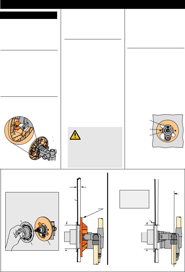
1)Determine wall thickness
■■Determine type of wall and wall thickness where valve will be mounted.
■■Consider whether to use mounting plate by reviewing figure 2 below.
■■Skip ahead to Step 3 if mounting plate is not used.
2)Attach valve mounting plate
Seat mounting plate against valve assembly as illustrated in figure 1.
Figure 1 Mounting plate
3)Attach protective shield
■■Reference figure 2 to determine whether shield is required.
■■Attach protective shield by snap fitting over end of valve spindle.
4)Install piping, fittings and control valve
Piping and fittings not supplied
■■Control Valve
Install through cutout hole in wall as specified in figure 2 below and dimension illustration on page 4.
■■Showerhead (S on valve)
Pipe from outlet port on valve marked S to showerhead mounting arm location.
■■Hot & Cold Supply (H & C)
Pipe hot water supply to valve inlet marked H and cold water supply to valve inlet marked C.
■■Tub Spout (T on valve)
Pipe from outlet port on valve marked T to tub spout.
Important! Do not substitute Tub Spout with restrictive fittings such as
PEX, CPVC or outlet accessories such as a ledge spout, hose and spray that would subject the valve to excessive internal back pressure, otherwise operation will be compromised.
5)Remove protective shield
If protective shield was attached in Step 3 then remove shield snap fitted over the end of valve spindle once valve is securely installed and wall finish work has been completed.
6)Adjust valve packing nut
Reference figure 3 below
■■Turn hot & cold supplies on. Valve will not operate unless both hot and cold water supply pressures are turned on.
■■Place handle over end of control spindle stem.
■■Adjust packing nut for positive frictional resistance as handle is rotated from shutoff position across adjustment range.
Temp Limit |
|
stop screw |
|
packing nut |
|
control |
|
spindle |
|
stem |
wall |
Figure 3 Valve adjustments
Walls for using T-177 mounting plate
Fiberglass or acrylic walls (required)
Plaster or other type walls (optional) 1/16" (2 mm) min 1/2" (13 mm) max
Protective shield |
nished |
When mounting plate is used, |
|
then shield is optional for |
wall |
protecting end of valve during |
|
installation. |
|
"snap on-off" |
|
p/n T-176 p/n T-177
wall cutout hole size  3-1/2" (95 mm) min
4" (101 mm) max
Ensure valve’s mounting plate is ush against inner wall
Dry wall, plaster or other type wall
1/2" (13 mm) or greater 

 nished wall
2-3/8" ± 1/2" 
(60 mm ±13 mm) pipe centerline to nished wall
Finished wall must beush with back side of protective shield surface
Protective shield
"snap on-off" 


(required when mounting plate is not used)
wall cutout hole size  3-1/2" (89 mm) min
4" (101 mm) max
Figure 2 Mounting valve
Page 2
 Loading...