


Advanced security made easy
™
™
plug&playsecurity
DVR4-5000™
4 Channel Digital Video Recorder with Built-In 10.2” LCD Screen
Operating Instructions
SW349-DAT
www.swannsecurity.com
SR349-DAT-60010-130809
1

Before You Begin
FCC Verification:
NOTE: This equipment has been tested and found to comply with the limits for Class B digital device, pursuant to part 15 of the FCC Rules. These limits are designed to provide reasonable protection against harmful interference in a residential installation. This equipment generates, uses and can radiate radio frequency energy and, if not installed and used in accordance with the instructions, may cause harmful interference to radio or television reception, which can be determined by turning the equipment off and on, the user is encouraged to try to correct the interference by one or more of the following measures:
·Reorient or relocate the receiving antenna
·Increase the separation between the equipment and the receiver
·Connect the equipment into an outlet on a circuit different from that to which the receiver is connected
·Consult the dealer or an experienced radio/TV technician for help
These devices comply with part 15 of the FCC Rules. Operation is subject to the following two conditions:
(1)These devices may not cause harmful interference, and
(2)These devices must accept any interference received, including interference that may cause undesired operation.
IMPORTANT NOTE: Prohibition against eavesdropping
Except for the operations of law enforcement officers conducted under lawful authority, no person shall use, either directly or indirectly, a device operated pursuant to the provisions of this Part for the purpose of overhearing or recording the private conversations of others unless such use is authorized by all of the parties engaging in the conversation.
WARNING: Modifications not approved by the party responsible for compliance could void user’s authority to operate the equipment.
IMPORTANT SAFETY INSTRUCTIONS:
·Make sure product is fixed correctly and stable if fastened in place
·Do not operate if wires and terminals are exposed
·Do not cover vents on the side or back of the DVR and allow adequate space for ventilation
DEFAULT PASSWORD INFORMATION
·This DVR is password protected.
·To unlock the DVR for the first time, the default password is “111111”.
·To ensure your ongoing privacy, we strongly recommend changing the password as soon as possible. Choose something that you’ll remember, but that others would be unlikely to guess.
·If you do manage to lock yourself out of the DVR, you’ll need to contact us at the
Swann Technical Support Telephone Helpdesk - the number is on the back cover.
2

Contents
Before You Begin |
2 |
Contents |
3 |
Package Contents |
4 |
Overview |
4 |
DVR Layout |
5-6 |
Connections & Installation |
|
Connecting Cameras and Power Adapter |
7 |
Connecting and Using the Mouse |
8 |
Turning the DVR On/Off and Auto Recovery |
8 |
Menu Operation |
9 |
Accessing and Navigating the Menu System |
9 |
Setting DVR Time |
9 |
Image Display |
10 |
Single Camera View |
10 |
Multi Camera View |
10 |
Camera Menu |
11 |
Record Menu |
11-12 |
Screen Menu |
12 |
Motion Detection Menu |
13 |
Alarm Menu |
13 |
Audio Menu |
14 |
System Menu |
14-15 |
Time Search |
15 |
Language Menu |
16 |
Exit Menu |
16 |
Starting the DVR With a New Hard Drive |
16 |
Changing the Hard Drive |
17 |
Backing Up Footage to PC |
18 |
Viewing Backup Footage on a PC |
19 |
Using the VVFPlayer software |
19 |
VVFPlayer Interface |
19 |
Extract footage from a larger video clip |
20 |
Exporting an AVI file |
20 |
Troubleshooting Guide |
21 |
Technical Specifications |
22 |
Warranty Information |
23 |
Technical Support Details |
Back cover |
3

Package Contents

 DVR4-5000™ 10.2” LCD Digital Video Recorder

 320GB Hard Drive (already installed)

 Remote Control (with Batteries)

 PS2 Mouse

 Power Adapter with Cable

 Security Stickers (4 Pack)

 Software CD

 Operating Instructions
If you are missing any of the 
 Easy Setup Guide components above, contact
Swann Communications for assistance.
Overview
Congratulations on your fine choice in stand-alone video monitoring systems!
The DVR4-5000 is a reliable, cost-effective digital video recorder with the added convenience of a built-in LCD screen. It will, when properly configured, autonomously work around the clock, recording incidents as they happen to its built in hard drive.
The DVR4-5000 is also easy to use: we’ve included a PS2 mouse which makes navigating through the menus a breeze. There’s also a remote control for added convenience.
The DVR4-5000 can monitor up to four cameras simultaneously - so, if you need to upgrade your system in the future, there’s room for you to do so.
Oh, and the stylish appearance of the unit doesn’t actually affect its performance, but it does look really cool. Which always helps.
The default password to unlock the DVR is “111111”.
4
Layout of DVR

 Front Panel
1 |
8 |
10 |
|
|
|
|
|
|
|
|
|
|
|
|
|
|
|
|
|
|
|
|
|
|
|
|
|
|
|
|
|
|
|
|
|
|
|
|
|
|
|
|
|
|
|
|
|
|
|
|
|
|
|
|
|
|
|
|
|
|
|
|
|
|
|
|
|
|
|
|
|
|
|
|
|
|
|
|
|
|
|
|
|
|
|
|
|
|
|
|
|
|
|
|
|
|
|
|
|
|
|
|
|
|
|
|
|
|
|
|
|
|
|
|
|
|
|
|
|
|
|
|
|
|
|
|
|
|
|
|
|
|
|
|
|
|
|
|
|
|
|
|
|
|
|
|
|
|
|
|
|
|
|
|
|
|
|
|
|
|
|
|
|
|
|
|
|
|
|
|
|
|
|
|
|
|
|
|
|
|
|
|
|
6 |
7 |
|
|
4 |
|
5 |
8 |
|
2 |
|
11 |
|
|
|
|
9 |
|
12 |
||||||||||
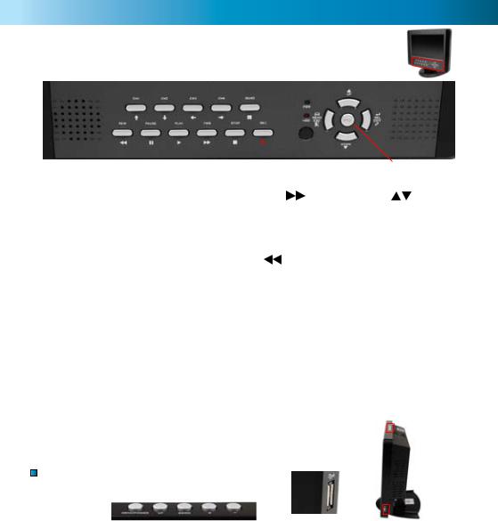
1. Quad & Channels 1 to 4 |
|
|
5. FWD (Fast-Forward) |
|
|
9. UP / DOWN |
|||||||||||||||||||||||
Changes the viewing mode on |
|
|
Press to speed up playback. The |
Used for navigation and to |
|||||||||||||||||||||||||
the DVR. Channels 1 through 4 |
|
|
more FWD is pressed, the faster |
change values in the menus. |
|||||||||||||||||||||||||
will display that channel. Quad |
|
|
the footage will play (choose |
10. SELECT / EDIT |
|||||||||||||||||||||||||
will display a split-screen view |
|
|
from x2, x3 and x4 speeds). |
|
|
||||||||||||||||||||||||
divided |
into four |
windows. |
|
|
6. REW (Rewind) |
|
|
|
|
|
Selects |
and confirms value |
|||||||||||||||||
When viewing the menu, the |
|
|
|
|
|
|
|
changes in the menu. |
|||||||||||||||||||||
Channel buttons are used for |
|
|
When playing back, press REW |
11. LEDS / IR SENSOR |
|||||||||||||||||||||||||
navigation. |
|
|
|
|
|
|
|
to play footage backwards. The |
|||||||||||||||||||||
2. REC (Record) |
|
|
|
|
|
|
|
speed and quality of rewind- |
The red LED lights up whilst in |
||||||||||||||||||||
|
|
|
|
|
|
|
ing footage will depend on the |
record or playback mode. The |
|||||||||||||||||||||
The REC button will engage |
|
|
quality settings when it was re- |
green LED is lit whilst the unit |
|||||||||||||||||||||||||
manual |
recording mode. The |
|
|
corded. |
|
|
|
|
|
|
|
|
is supplied with power and |
||||||||||||||||
record icon will be displayed |
|
|
7. PAUSE |
|
|
|
|
|
|
|
|
turned on. The IR sensor is for |
|||||||||||||||||
onscreen whilst the DVR is re- |
|
|
|
|
|
|
|
|
|
|
the infrared remote control. |
||||||||||||||||||
cording. |
|
|
|
|
|
|
|
|
|
|
Pauses playback. |
|
|
|
|
|
12. PTZ (Pan, Tilt, Zoom) |
||||||||||||
3. STOP |
|
|
|
|
|
|
|
|
|
|
8. MENU / ESC |
|
|
|
|
|
|||||||||||||
|
|
|
|
|
|
|
|
|
|
|
|
|
|
|
Press PTZ to enter Pan, Tilt, |
||||||||||||||
Stops playback. |
|
|
|
|
|
|
|
Opens the DVR menu when in |
Zoom control mode. |
||||||||||||||||||||
4. PLAY |
|
|
|
|
|
|
|
|
|
|
live viewing or playback modes. |
|
|
|
|
|
|
|
|
||||||||||
|
|
|
|
|
|
|
|
|
|
When in a menu, this button |
|
|
|
|
|
|
|
|
|||||||||||
Once an event has been record- |
|
|
will take you back to the pre- |
|
|
|
|
|
|
|
|
||||||||||||||||||
ed, use PLAY to enter playback |
|
|
vious screen or menu you were |
|
|
|
|
|
|
|
|
||||||||||||||||||
mode. You will be taken directly |
|
|
in. |
|
|
|
|
|
|
|
|
|
|
|
|
|
|
|
|
|
|
||||||||
to the time-search interface. |
|
|
|
|
|
|
|
|
|
|
|
|
|
|
|
|
|
|
|
|
|
|
|
||||||
Top Panel and Side USB port |
|
|
|
|
|
|
|
|
|
|
|
||||||||||||||||||
|
|
|
|
|
|
|
|
|
|
|
|||||||||||||||||||
|
|
|
|
1 |
|
2 |
3 |
4 |
5 |
|
|
|
|
|
|
|
|
|
6 |
|
|
||||||||
|
|
|
|
|
|
|
|
|
|
|
|
|
|
|
|||||||||||||||
|
|
|
|
|
|
|
|
|
|
|
|
|
|
|
|
|
|
|
|
|
|
|
|
|
|
|
|
|
|
|
|
|
|
|
|
|
|
|
|
|
|
|
|
|
|
|
|
|
|
|
|
|
|
|
|
|
|
|
|
|
|
|
|
|
|
|
|
|
|
|
|
|
|
|
|
|
|
|
|
|
|
|
|
|
|
|
|
|
|
1. MENU / POWER
Press quickly to display the LCD configuration menu or move the cursor to the right. Press and hold for a few seconds to turn the screen (not the DVR itself) on or off.
2. DOWN
Move the parameter prompt in the LCD menu downwards.
3. UP
Move the parameter prompt in the LCD menu upwards.
4. & 5. + / -
Increases/decreases the volume of the built-in speakers when not in the LCD menu. When in the LCD menu, these buttons alters the selected value.
6. SIDE USB PORT
Used for attaching a compatible USB flash drive, for backing up footage.
Note: Do not connect the DVR to a computer, or to any device other than a USB flash drive.
Other devices may be harmed, or harm the DVR.
5
DVR Layout (cont)

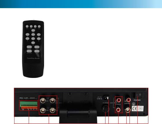
 Remote Control
|
|
|
|
|
|
|
|
|
|
|
|
|
|
1. |
Channel 1 - 4, Quad |
|
1 |
|
|
|
|
|
|
|
|
|
|
|
|
|
2. Rew |
||
|
|
|
|
|
|
|
|
|
|
|
|
|
||||
|
|
|
|
|
|
|
|
|
|
|
|
|
3. |
Play |
||
|
|
|
|
|
|
|
|
|
|
|
|
|
||||
2 |
|
|
|
|
|
|
|
|
|
|
|
|
|
|||
|
|
|
|
|
|
|
|
|
|
|
|
4 |
|
|
||
3 |
|
|
|
|
|
|
|
|
|
|
|
4. Fwd |
||||
|
|
|
|
|
|
|||||||||||
|
|
|
|
|
|
|
|
|
|
|
|
6 |
||||
5 |
|
|
|
|
|
|
|
|
|
|
|
|||||
7 |
5. |
REC |
||||||||||||||
|
||||||||||||||||
8 |
|
|
|
|
|
|
|
|
|
|
|
|
|
|||
|
|
|
|
|
|
|
|
|
|
|
|
11 6. |
Pause |
|||
9 |
|
|
|
|
|
|||||||||||
|
|
|
|
|
|
|||||||||||
10 |
|
|
|
|
|
12 |
7. |
Stop |
||||||||
|
|
|
|
|||||||||||||
|
|
|
|
|
|
|
|
|
|
|
|
|
||||
|
|
|
|
|
|
|
|
|
|
|
|
|
|
8. |
PTZ |
|
|
|
|
|
|
|
|
|
|
|
|
|
|
|
9. |
Menu/Esc |
|
10. |
Select/Enter |
11. |
Up |
12.Down
Functions:
All buttons on the remote control operate in exactly the same manner as their namesake on the front panel of the DVR.
In fact, the remote control is essentially an exact copy of the front interface of the DVR, somewhat rearranged.
Thus, it does not matter at all whether you use the front panel or the remote control - the remote is simply for your convenience.

 Rear Panel
81
1.VIDEO INPUT
Where you connect your cameras, using BNC connectors. If any of your cameras use RCA connectors, you’ll need to use an RCA to BNC adaptor.
2. VIDEO OUTPUT
A composite video output. You can use this to connect the DVR to another monitor (such as a television). The additional monitor will display the same image(s) as the incorporated monitor.
3. AUDIO INPUT
You can connect two audio sources to the DVR. The audio sources may be microphones from your cameras, or separate audio sources.
4. AUDIO OUTPUT
A line-level audio output. Can be connected to a television, amplifier or external recording device. Will output the same signal as heard on the builtin speakers.
5 6 |
3 |
2 4 |
7 |
5. PS2 MOUSE
To attach a PS2 compatible mouse (included).
6. DC 12V
Connect the included power supply to this connection.
7. MASTER POWER SWITCH
Turns the DVR on and off. Overrides the button on the top of the unit.
8. RS485 / ALARM / SENSOR
SENSOR: For connecting up to four external sensors to the DVR.
ALARM: To connect an alarm output to the DVR. RS485: These two ports are RS485 asynchronous serial connectors. Typically, these are used to control PTZ capable systems.
Note: These are advanced features of the DVR, and are recommended for experienced users and/ or professional installations.
6

Connecting Cameras and Power Adapters
1 3
 4
4
2 |
5 |
|
1.Connect the Power and BNC ends of the
MaxiBright Camera to an Extension Cable.
2.Connect the end of the BNC Extension Cable to a Video Input on the back of the DVR.
3.Connect the Power Connector of the
Extension Cable to the Power Splitters.
4.Connect the Power Splitter to the Camera Power Adapter.
5.Plug in the Camera Power Adapter and the DVR Power Adapter to mains power outlets.
Tips and Tricks
Connecting the cameras and the DVR is relatively straight forward. However, there are a couple of things that can go amiss, particularly if you’re not familiar with connecting A/V equipment. Here’s a couple of points to watch out for:
1.Double check if your plugging a cable into an input or an output. Plugging a camera into an output will not yield any useful results, likewise attaching a TV to an input won’t display anything.
2.When installing cables, avoid placing cables too near mains electrical cables. AC power generates an electromagnetic field which will interfere with information being transmitted along the cable.
3.For best results, avoid joining cables together. Joining cables reduces signal integrity - if you really need a longer cable, we suggest purchasing a longer extension cable.
7

Using the Mouse

 Attaching the Mouse
Plug the PS2 connector for the mouse into the PS2 port on the back of the DVR.
Note that the USB port on the side of the DVR does not support a mouse being connected. The DVR is compatible with a PS2 mouse only.

 Using the PS2 Mouse
When a mouse is connected, a cursor will be displayed on the screen which can be moved by moving the mouse, much like the mouse cursor on a computer.
Click the left mouse button to select an item or to change a setting in a menu. Additionally, in quad-view, click a channel to enlarge it to full-screen.
When in the menu system, use the right mouse button to go up one level. When in the live viewing or playback mode, right clicking the screen will bring up a quicktask bar, containing playback controls and a menu icon. These operate in the same manner as the physical buttons they represent.
Turning the DVR On/Off and Auto Recovery

 Powering the DVR On/Off
To turn on your DVR connect the Power Adapter to the DC 12V input on the back of the unit. Turn the master power switch on the back of the DVR on. This will power on the DVR itself.
If the screen does not turn on, press and hold the power button on the top of the DVR.
To turn the screen off, press and hold the power button on the top panel. To completely turn off the DVR, use the master power switch on the rear panel.

 Auto-Recovery Feature
The DVR4-5000™ is equipped with an Auto-Recovery feature. Should a power outage occur while you are recording the DVR will automatically resume recording once power is restored.
8
 Loading...