


English
960H
Digital Video Recorder
8/9-channel models
EN |
|
INSTRUCTION MANUAL |
1

Before You Begin
FCC Verification
Note: This equipment has been tested and found to comply with the limits for Class B digital device, pursuant to part 15 of the FCC Rules. These limits are designed to provide reasonable protection against harmful interference in a residential installation. This equipment generates, uses and can radiate radio frequency energy and, if not installed and
used in accordance with the instructions, may cause harmful interference to radio or television reception, which can be determined by turning the equipment off and on, the user is encouraged to try to correct the interference by one or more of the following measures:
•Reorient or relocate the receiving antenna
•Increase the separation between the equipment and the receiver
•Connect the equipment into an outlet on a circuit different from that to which the receiver is connected
•Consult the dealer or an experienced radio/TV technician for help
These devices comply with part 15 of the FCC Rules. Operation is subject to the following two conditions:
•These devices may not cause harmful interference, and
•These devices must accept any interference received, including interference that may cause undesired operation.
IMPORTANT NOTE:
All jurisdictions have specific laws and regulations relating to the use of cameras. Before using any camera for any purpose, it is the buyer’s responsibility to be aware of all applicable laws and regulations that prohibit or limit the use of cameras and to comply with the applicable laws and regulations.
FCC Regulation (for USA): Prohibition against eavesdropping
Except for the operations of law enforcement officers conducted under lawful authority, no person shall use, either directly or indirectly, a device operated pursuant to the provisions of this Part for the purpose of overhearing or recording the private conversations of others unless such use is authorized by all of the parties engaging in the conversation.
WARNING
Modifications not approved by the party responsible for compliance could void user’s authority to operate the equipment.
IMPORTANT SAFETY INSTRUCTIONS
•Make sure product is fixed correctly and stable if fastened in place
•Do not operate if wires and terminals are exposed
•Do not cover vents on the side or back of the DVR and allow adequate space for ventilation
2
DEFAULT PASSWORD INFORMATION
To ensure your privacy, this DVR supports password protection.
The default, all-access username is ‘admin’, the default password is ‘12345’.
To ensure your ongoing privacy, we strongly recommend setting a password as soon as possible. Choose something that you’ll remember, but that others would be unlikely to guess.
IMPORTANT NOTICE - Do NOT lose or forget your password. To ensure that your DVR has the best security possible, password recovery has been designed to be a complicated and time consuming process. Only a select number of staff at theSwann Technical Support Telephone Helpdesk can assist. Password retrieval can take several days, which means you willNOT be able to access your DVR during this time.
BATTERY INFORMATION
This product contains a removable battery. If you need to replace or dispose of the internal battery.
The battery is located on the mainboard of the DVR. It is a primary lithium CR2032 button cell.
To access, remove and/or replace the battery:
• Ensure the DVR is turned OFFNEVER. open the DVR’s case while power is connected.
•Remove the five screws holding the cover on the DVR.
•If replacing the battery, ensure that it is an exact match for size, type andcapacity.
•Be sure to safely dispose of the battery. The process for battery disposal/recycling varies from location to location, please check with the relevant local authority for method.
BATTERY SAFETY INSTRUCTIONS
•Do NOT attempt to open, puncture, disassemble or modify the battery in any way.
•Do NOT subject it to sudden shock or heat.
•Do NOT dispose of battery in fire.

Contents
|
|
|
System: General |
46 |
Introduction |
|
|||
|
|
System: User |
47 |
|
Getting Started |
5 |
|
||
|
System: System Information |
48 |
||
Installation Guidelines |
6 |
|
System: Maintenance |
49 |
DVR Front Panel |
6 |
|
|
|
DVR Rear Panel |
7 |
|
|
|
|
Reference |
|
||
Connection Diagram |
8 |
|
|
|
Connecting Additional Devices |
9 |
|
SwannView Link Windows Interface |
51 |
|
|
|
SwannView Link: Local Settings |
52 |
|
|
|
SwannView Link: Device Settings |
53 |
Basic Setup |
|
|||
|
|
SwannView Link Mobile Interface |
57 |
|
Controlling the DVR |
11 |
|
Troubleshooting |
59 |
Setup Wizard: General |
12 |
|
Third Party Hardware |
60 |
Setup Wizard: Email |
13 |
|
Warranty Information |
61 |
Setup Wizard: System Time |
14 |
|
Helpdesk / Technical Support Details |
Rear |
Setup Wizard: Account Configuration |
15 |
|
|
|
Setting up your Smartphone or Tablet |
16 |
|
|
|
Setting up your PC |
17 |
|
|
|
Live View Mode |
20 |
|
|
|
About 960H Widescreen Videos |
20 |
|
|
|
Menu Layout |
21 |
|
|
|
|
|
|
|
|
Menu Functions |
|
|
|
|
Overview |
23 |
|
|
|
Display: Camera |
24 |
|
|
|
Display: Output |
25 |
|
|
|
Recording: Encode |
26 |
|
|
|
Recording: Option |
27 |
|
|
|
Recording: Schedule |
28 |
|
|
|
Search: Playback |
29 |
|
|
|
The Playback Interface |
30 |
|
|
|
Specific Incident Backup |
31 |
|
|
|
Search: Backup |
31 |
|
|
|
Search: Event / Log Search |
32 |
|
|
|
Network: General |
33 |
|
|
|
Network: Advanced |
34 |
|
|
|
Network: Advanced: DDNS |
35 |
|
|
|
Network: Advanced: NTP |
35 |
|
|
|
Network: Advanced: Email Settings |
36 |
|
|
|
Network: Advanced: IP Filter |
37 |
|
|
|
Network: Network Status |
37 |
|
|
|
Alarm: Motion |
38 |
|
|
|
Alarm: Motion Detection Configuration |
39 |
|
|
|
Alarm: Motion Detection Notes |
40 |
|
|
|
Alarm: Motion Detection - Action |
41 |
|
|
|
Alarm: Video Loss |
41 |
|
|
|
Alarm: Exception |
42 |
|
|
|
Device: HDD |
43 |
|
|
|
Device: S.M.A.R.T. |
43 |
|
|
|
Device: PTZ |
44 |
|
|
|
3

Chapter
1
Introduction
4

EN INTRODUCTION
Getting Started
Congratulations on your purchase of this Swann DVR. You’ve made a fine choice for keeping a watchful eye over your home or business. Let’s take a moment to talk about some of the features this DVR offers, and how to get the most out of them.
Oh my, this is a big manual. How long will this take?
Yes, but you won’t have to read all of it - you should be up and running by page 20!
It can take a few hours to connect everything and run through the setup procedure.
The latter half of this manual is for users who want to get the most out of the DVR’s capabilities. While the DVR is seriously configurable, the out-of-the-box settings do a great job in 90% of situations, but some users will want to get into the nitty-gritty detail, so that information is presented for those who need it.
The Basic Setup
The default settings of the DVR will cover most basic installation requirements of the DVR.
To get the most out of your hard drive, we’ve configured the DVR to record only when it detects motion - that way, you won’t fill the hard drive with video of nothing happening.
Before installing anything, connect the DVR and cameras and test your system.
We ensure everything is working properly when we ship them out, but sometimes things can be damaged in
transport, and occasionally components can fail. Better to find out now, before everything is fixed in place!
Getting the DVR Setup
There are three stages to getting your DVR set up. If you want to use the default settings, you’ll only need to complete steps one and two.
1. Connecting the DVR (page 6 topage 9 )
This section details what you can connect to the different inputs/outputs of the DVR.
Everyone’s setup will vary a little bit - it depends on what cameras came with the DVR (if any) and what device(s) you’ve already got.
2. Basic DVR Setup
The DVR needs a few things to be set properly before it can do its thing. Follow the instructions frompage 12 topage 18
to get everything working.
3. Optional: DVR Menu Functions
The latter part of this manual is a how-to guide on using the menus in the DVR system to perform common and advanced DVR operations.
Take your time to read through this chapter and explore the many capabilities that this Swann DVR can offer you. You will learn how to do things like adjusting the video display settings, searching for recordings, customizing alarm motion settings to something that’s more appropriate for your circumstances and lots more.
Note: The out-of-the-box settings really do work well, and we’d only suggest changing them if you’ve got a really specific plan in mind.
Accessing this DVR from your Smartphone or Tablet
This DVR supports live viewing on your Smartphone or Tablet. We have developed an app called SwannView Link for the AndroidandiOSplatforms.ForAndroidusers,pleasedownload the app from Google Play. If you have an Apple device, please go to the Apple App Store. As we are continually improving the documentation that we include with our products, you can find the latest user guide for our app at www.swann.com.
Now with extra “H”: 960H and what it means
This DVR is compatible and is intended for use with 960H cameras. What does this really mean?
A traditional CCTV camera operates at a resolution of approximately 720 x 480 (NTSC) or 720 x 576 (PAL) pixels* and a 4:3 aspect ratio. By extending the image to a widescreen format, 960H technology increases the horizontal resolution of the camera, thereby increasing the area viewed and the resolution it’s viewed at.
In general, 960H is best suited:
•monitoring a wider area than traditional CCTV cameras could cover at the same detail
•being displayed on high-definition widescreen televisions/monitors
•for upgrading from traditional CCTV cameras, while reusing previously installed coaxial cables.
*The resolution is approximate as analog video doesn’t really work this way. The resolution listed is the equivalent for a standard pixel matrix.
INTRODUCTION
5

INTRODUCTION
EN INTRODUCTION
Installation Guidelines
•Do not expose the DVR to moisture. Water is the archenemy of electrical components and also poses a high risk of electric shock.
•Avoid dusty locations. Dust has a tendency to build up inside the DVR case, leading to a high risk of failure or even fire.
•Only install the DVR in a well ventilated space. Like all electronics, the circuitry and hard drive in the DVR produce heat, and this heat needs a way out.
•Do not open the DVR case except to install/swap the hard drive inside. There are no user serviceable parts inside.
•Do not cut or modify any cable for any reason. Doing so
will void your warranty, as well as pose a great risk of fire or electrical shock.
•Do not expose the DVR to sudden bumps or shocks (for example, being dropped). The DVR is as robust as possible, but many of the internal components are quite fragile.
•Remember that the DVR is, in all likelihood, going to be left on 24 hours a day, 7 days a week. Keep this in mind when choosing a location for installation.
•Never open the case whilst the DVR is plugged in, and never turn the DVR on whilst the case is open.
DVR Front Panel
1 |
2 |
3 |
4 |
5 |
6 |
7 |
8 |
*8-Channel DVR4200 model shown above. Availability of the buttons described here can vary in some models.
|
|
||
Name |
Function |
||
1 |
USB Port |
ForconnectingUSBexternalstoragetotheDVRforbackup,orforapplyingnewfirmware. |
|
|
|
|
|
2 |
Play/Pause |
Opens the playback interface from the live viewing mode. Pauses playback or resumes |
|
Button |
playback. |
||
|
|||
3 |
Display Button |
Toggles between full screen and split-screen views. |
|
|
|
|
|
4 |
Menu Button |
Opens the DVR’s menu, or goes back one step from a submenu. |
|
5Select Button For selecting menu options in the DVR system.
6Directional Pad For navigating around menus in the DVR system.
7 |
Power LED |
Power indicator. This LED lights up when the DVR is switched on. |
|
|
|
8 |
HDD LED |
Hard Drive Indicator. This LED blinks rapidly when the hard drive is active. |
6
EN INTRODUCTION
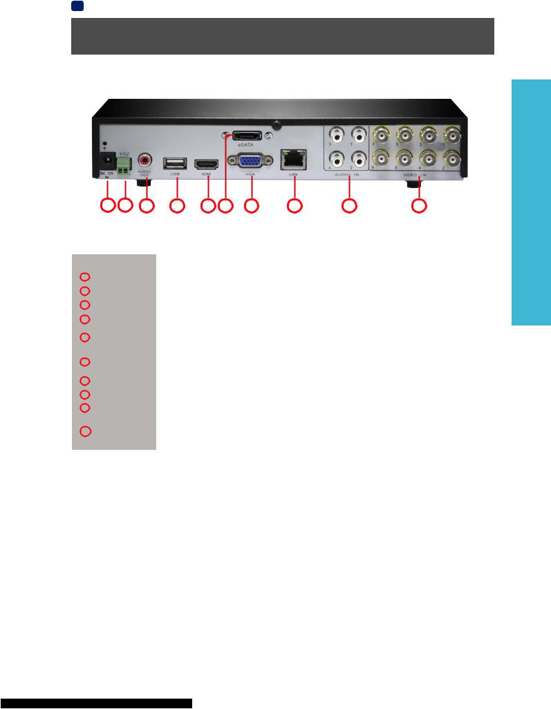
DVR Rear Panel
1 |
2 |
3 |
4 |
5 |
6 |
7 |
8 |
9 |
10 |
|
|
||
Name |
Function |
||
1 |
Power Input |
This is where you connect the supplied DC 12V power adapter to your DVR. |
|
2 |
PTZ |
For connecting RS485 cables to control a PTZ (pan, tilt, zoom) device on the DVR. |
|
3 |
AUDIO OUT |
RCA port for audio output. Used to connect your speaker or headphone. |
|
|
|
|
|
4 |
USB |
For connecting the USB mouse. |
|
5 |
HDMI |
The primary video output of the DVR. For the highest possible video output quality, we |
|
suggest using this output on a use a monitor/television capable of displaying Full HD 1080p. |
|||
|
|
||
6 |
eSATA |
To connect an external hard drive which will act as a live recording drive in the same |
|
manner as the installed HDD. |
|||
|
|
||
7 |
VGA |
For connecting a television or PC monitor with a VGA input. |
|
|
|
|
|
8 |
LAN |
Connect to your home network router using an Ethernet cable to access the Internet. |
|
9 |
AUDIO IN |
RCA ports for connecting microphones to record audio. |
|
|
VIDEO IN |
These are your video inputs where you connect your cameras via the BNC connector to |
|
10 |
display video feed on your TV. The channels are labelled by numbers in the same order as |
||
|
|
they appear on your DVR’s Live View interface. |
|
INTRODUCTION
7

EN INTRODUCTION
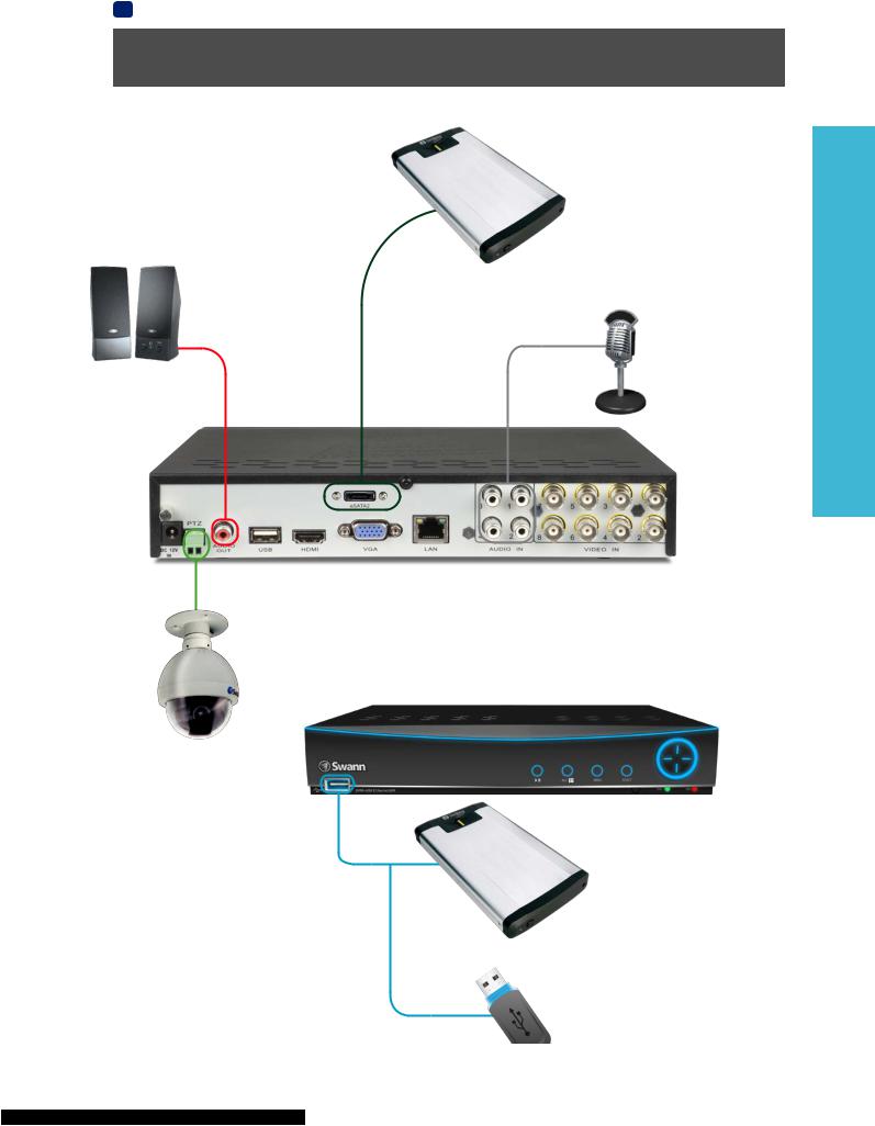
Connection Diagram
INTRODUCTION
Connect the Video (BNC-connector) and Power cables from the camera to the extension cable then connect the Video cable on the other end of the extension cable to a Video input on the rear of the DVR. Do this for the other cameras in your kit.
Connect the power supply to the Power input on the DVR and then plug it into a wall outlet.
Connect the cameras to power using the power splitter then connect the power adapter to a wall outlet.
Connect the mouse to the USB port.
If you’ve got a TV or monitor with HDMI in, connect to the HDMI port on the DVR.
8
Connect the Ethernet cable from the LAN port on the DVR to a spare port on your router.
If you’ve got a monitor with VGA but not
HDMI, connect it to the VGA output on the
DVR.
EN INTRODUCTION
Connecting Additional Devices
The Audio Out port can be used to connect a pair of speakers or headphones.
The PTZ port (RS485) can be used to connect compatible PTZ devices, such as this Swann PTZ dome.
An external hard drive with a USB-compatible interface (USB 2.0 recommended) can be connected to the front USB port of the DVR.
The front USB port also supports USB solid-state storage, such as flash drives.
An external hard drive with an eSATA port can be connected to the eSATA port on the DVR.
It can be used to record live footage in the same way as the interal HDD(s).
The Audio In ports can be used to connect audio devices such as microphones to the DVR.
INTRODUCTION
9

Chapter
2
Basic Setup
10
EN BASIC SETUP
Controlling the DVR
Starting the DVR for the first time:
When you first boot the DVR, it will automatically start the Setup Wizard which will guide you through the various setup options available.
The USB Mouse
The easiest way to operate the DVR is to use the included USB optical mouse - we put together the look and feel of the menu system specifically for mouse-friendly navigation.
The controls are pretty easy to remember - heck, there are only two buttons. It couldn’t be simpler.
Left click:
Selects an item or confirms a choice.
Right click:
Opens the menu bar from the live viewing screen. Returns one “step” from a submenu.
Opens a context menu in some settings screens.
The Scroll Wheel:
Can be used to adjust the values of sliders and scales when highlighted by the mouse.
The Remote Control
The DVR also comes supplied with a remote control unit. Like the USB Mouse, it can be used to perform all the main functions of the DVR. For details of what each button does, see the layout of the remote control below.


 Wireless Mice and Bluetooth devices are NOT compatible with the DVR.
 Please use the USB optical mouse supplied.
Shutting Down & Rebooting
If you want to shut down or reboot the DVR, or simply log out of the user account you’re logged in as, access the Shutdown menu which is accessible via the main menu.
To ensure the integrity of your data and recordings, always selectShut Down when powering off the DVR.
BASIC SETUP
11
EN BASIC SETUP
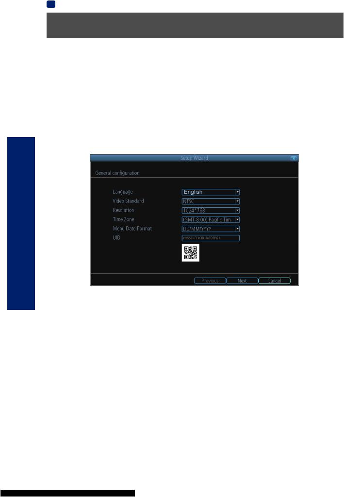
Setup Wizard: General
The Setup Wizard will run automatically the first time you start the DVR.
The wizard will guide you through all the settings you need to get your DVR up and working, specifically:
•Choosing your Language
•Setting Video Format and Resolution
•Setting the Date Format and your Time Zone
•Configuring your email account settings so that the DVR can send you alerts and the DVR UID
•Synchronizing the DVR’s time with an online server
•Choosing the settings for Daylight Savings Time (DST)
•Changing the DVR’s Admin account default password
General Configuration
SETUP BASIC
Language: Choose the language you’d like the menu system to be displayed in.
Video Standard: Choose between NTSC (for the USA, Canada, Mexico, Japan, Korea and some other regions) or PAL (UK, Europe, Australia and some other areas). If this is set incorrectly, images from your cameras will be distorted, black and white, or simply not appear at all.
Resolution: The screen resolution setting for the DVR display. Typically, you’ll want to set this to be equal to the native resolution of your monitor/television (check the manufacturer’s documentation). For example, if the DVR is connected to your HDTV, you would want to set it to the highest possible setting, 1920 x 1080, to give you the best picture quality.
Time Zone:Choose the time zone you’re in. It’s really important to select the right time zone if you’re using NTP (Network Time Protocol).
Some common time zones: In the USA, EST (Eastern Standard Time) is GMT -5:00, where PST (Pacific Standard Time) is GMT -8:00. The UK is GMT +0:00, and the East Coast of Australia is GMT +10:00.
Menu Date Format: How you’d like the date to be displayed. Choose whichever format that’s standard in your region.
UID: This is the DVR’s Unique IDentifier number which you will use later to connect your PC or SmartPhone to the DVR using Swann’s Peer to Peer technology.
If you need to change any of these settings later, you can find these options here:Main Menu -> System -> General
12
EN BASIC SETUP
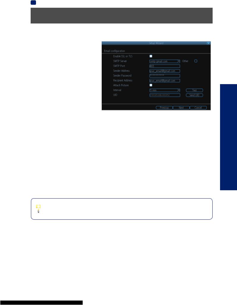
Setup Wizard: Email
If you want the DVR to send email alerts as alarm events are detected, then you’ll need to configure an outgoing email server for the DVR to use, and choose an email address for it to send to.
We recommend creating an account with Gmail (www.gmail.com) specifically for the DVR. These instructions assume you’re using a GMail account. If you’re using a different email, see “Network: Advanced: Email Settings” on page 36 for details.
Enable SSL or TLS:Enable.
SMTP Server: The SMTP address of your email server. There are 3 preset options to select from: smtp.gmail.com, smtp.live.com or smtp.mail.yahoo. com
Other: Allows for custom definintion of an outgoing email server. See“Network: Advanced: Email
Settings” on page 36 if you want to use an email server other than ones providedRecommended. for advanced users ONLY.
SMTP Port: The SMTP port of your email server. Gmail’s is 465(this value will self-populate)
Sender Address: The email address you want your DVR to send alerts from. For example,your_email @gmail.com Sender Password: The password of your sending email address.
Recipient Address Enter: an email address for the DVR to send alerts to (usually your personal email address).
Attach Picture: When selected, the DVR will attach a still image to better illustrate what has caused the alarm/alert state. Interval: The minimum amount of time that must elapse after the DVR sends an email alert before it can be triggered again.
Test: To check if you’ve set up email alerts properly, click the Test button. If your connection and email details are ok, you will see a message on the DVR screen confirming the email was sent successfully. After a short delay, you will also receive an e-mail in your inbox (Recipient’s Address) informing you that email alerts from the DVR has been set up. If the test is unsuccessful, please check your sender’s address/password and recipient’s address(es) and try again.
UID: This is the DVR’sU nique IDentifier number. We will use this UID to configure the SwannView Link app & software and connect to your DVR. You can click theSend UIDbutton to receive an email containing the UID (that’s assuming your email details are configured).
Send UID: When you’ve finished testing your email, click theS nd UIDbutton to send the DVR UID to your email address (Recipient’s Address) so you can use it for access from SwannView Link on your PC etc.
BASIC SETUP
Your DVR does not send out email alerts immediately when events occur. The frequency of email alerts depends on the “Interval” setting you specify here.
13
SETUP BASIC
14
EN BASIC SETUP
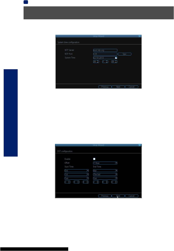
Setup Wizard: System Time
NTP
NTP stands for “Network Time Protocol”. It’s a way for the DVR to connect to the Internet and automatically update and maintain accurate time. There’s no requirement to use NTP, but it’s easy to setup and free to use, so there’s really no reason not to.
NTP Server: The default server used to obtain accurate time.
NTP Port: The default is123 . You should only change this if you’re using a different NTP server, and you know they use a different port. If you’re usingpool.ntp.org , ensure the port is 123.
Sync:Triggers the DVR to automatically synchronize its internal clock with the time server immediately. If your DVR is connected to the Internet, the DVR will update the time immediately.
System Time:The DVR’s current date and time.
DST Configuration
If your time zone observes daylight saving time and you want your DVR’s clock to be updated automatically when daylight saving time starts and ends, make sure theEnable checkbox is selected. You can configure when daylight saving time starts and ends, for example - 2 a.m. on the first Sunday of a particular month.
Note: Make sure your time offset is set correctly or both your DVR’s normal time and DST time may be out.
Offset: The amount by which the time changes during DST. For the vast majority of locations, the offset is one hour, but exceptions to this rule exist.
Start Time / End Time:When DST begins and ends in your locale.
EN BASIC SETUP
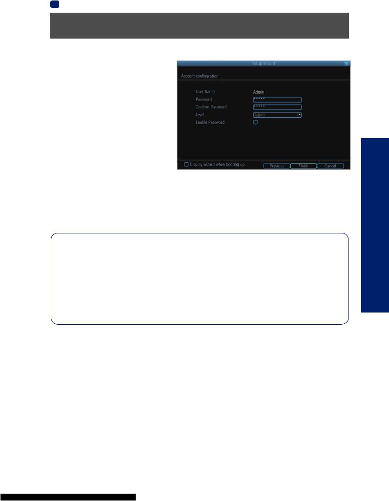
Setup Wizard: Account Configuration
Account Configuration
Here you can change the default password of the Admin account. For on-going protection against unauthorized access, we strongly suggest setting a new password for yourAdmin account.
User Name: The DVR’s default administration account, which is always called “Admin”. You can’t change theAdmin user name.
Password: The password you’d like to be associated with theAdmin account. A password can be between 1 and 8 characters in length, and consists of numbers only (no letters or symbols). The default password that’s masked on screen is “12345”.
Confirm Password: Re-enter the password to ensure accuracy.
Level: This field is greyed out because theAdmin
account always has the highest level of access. There are two additional access levels available - Guest and Operator.
Enable Password:Select this if you want to be prompted for the user account’s password when accessing the main menu. This adds an extra layer of authentication on your DVR
Display wizard when booting up (checkbox):Select this if you want the DVR to automatically run the configuration wizard when it boots up. You can also run the wizard at any time by clicking the  icon on the DVR menu bar.
Default Password Information
To ensure your privacy, this DVR supports password protection.
The default, all-access username is “admin”. If the DVR asks you to log in before you’ve set a password, enter admin as your username and leave the password blank. This will give you access to all areas of the DVR.
The password function is disabled by default. However, if you’re asked for a password, the default is “12345”.
To ensure your ongoing privacy, we strongly recommend setting a password as soon as possible. Choose something that you’ll remember, but that others would be unlikely to guess.
If you do manage to lock yourself out of the DVR, you’ll need to contact us at the Swann Technical Support Telephone Helpdesk - the number is on the back cover.
BASIC SETUP
Finishing the Setup Wizard
When you clickFinish , the DVR will update and save your settings. It may reboot while doing so.
15
SETUP BASIC
16
EN BASIC SETUP
Setting up your Smartphone or Tablet
Have a Smartphone or Tablet?
Then head to the respective Apple App Store or Google Play, downloadSwannViewthe Link app (orSwannView Link HD for tablets) for free and turn your iOS or Android device into a monitoring centre for your DVR. Have the peace of mind that you can monitor your home at any time from any place. With “SwannLink” Peer to Peer technology, connecting your smartphone, tablet or PC to your DVR is so easy - there’s practically no need to fiddle around with complicated network configuration. Best of all, it only takes minutes to get it all up and running!
Important Note: As the SwannView Link app is constantly under development to improve your user experience, the following screens may differ slightly from the actual app.
Configuring the SwannView Link App
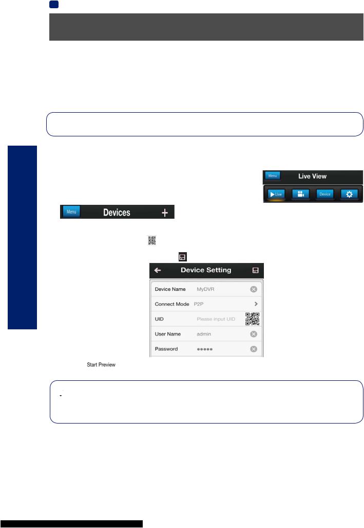
After you have downloaded and installed SwannView Link (HD) on your smartphone or tablet, locate the app and tap the icon to run. Take your smartphone/tablet to your DVR and follow the instructions below.
1.In theLive Viewscreen, tap  at the top left and then tap
 .
.
2.In theDevices menu, tap+ to add a new Device as shown below.
3.On the DVR you will see a sticker with a QR Code and your UID number (the sticker will be on the top or bottom of the DVR case depending on which DVR model you have).
On the app, tap the QR Code button and use your smartphone’s camera to scan the QR sticker on the DVR. This automatically populates theUID box with the DVR’s UID. Enter a Device Name (anything you like), the username and
password for your DVR as shown below and tap to save your settings.
4. Next, tap to automatically check the number of channels and then you will see your cameras on screen and that’s it, you’re connected!


 Need more details?
Full explanation of the SwannView Link’s app interface is detailed in the Reference chapter from page 57to page 58 .
EN BASIC SETUP
Setting up your PC
SwannView Link Software
Your DVR comes with powerful remote access and interface software, calledSwannView Link. You can setup and configure almost all aspects of the DVR from the SwannView Link interface.
The SwannView Link software will allow you to:
•view images from your DVR in real-time,
•playback recorded footage,
•copy footage to your local PC and
•adjust settings and configure the DVR.
In fact, theSwannView Link software is so powerful, you don’t even need to connect a monitor to the DVR if there’s a computer on the local network that you’re runningSwannView Linkon.
For quick and easy configuration of the DVR’s settings, recording quality and schedule, we suggest using the remote
interface inSwannView Link .
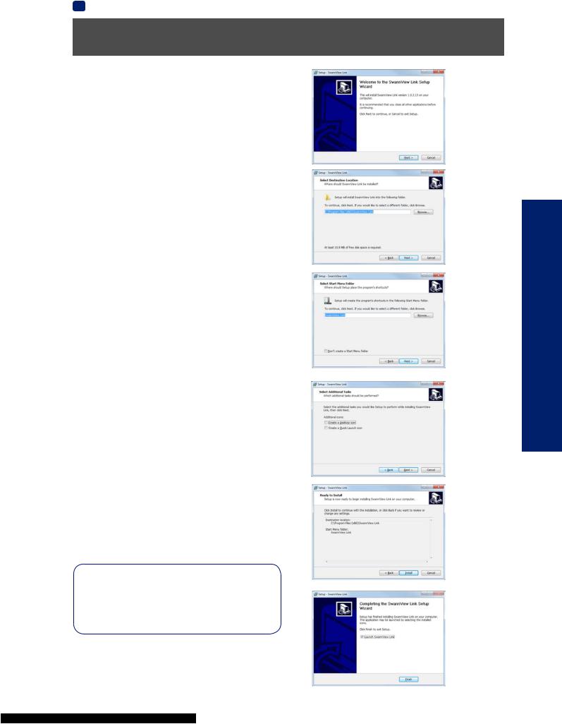
How to install SwannView Link:
•Insert the included CD into your computer.
•Click theSwannView Link PC Monitoring Software button from the Software Installation Menu to begin installation.
•You may be asked by UAC (User Account Control) to allow SwannView Link to “make changes” to your system. Select
Allow or Continue.
•You’ll see an installation wizard. Simply follow the prompts to install the software.
•Once theSwannView Link software is installed, it should automatically detect your DVR on your network.
Minimum PC Requirements:
2.0GHz or faster CPU |
(Dual-core recommended) |
1GB or more RAM |
(2GB recommended) |
10/100Mbps Network |
(1000Mbps recommended) |
Internet connection |
(512kbps+ recommended) |
1024x768 resolution |
(1280x720 recommended) |
Supported Operating Systems
Microsoft Windows XP, Microsoft Windows Vista,
Microsoft Windows 7 and Microsoft Windows 8
NOTE: Windows XP, Windows Vista, Windows 7 and Windows 8 are registered trademarks of Microsoft Corporation.
Got a Mac?
Check out www.swann.com/myDVRmac
for the latest Mac-based remote access software.
BASIC SETUP
17

SETUP BASIC
EN BASIC SETUP
Setting up your PC
Logging on to SwannView Link
•To connect from your PC to your DVR, make sure your DVR is on and all connections are ok.
•On your PC, open the email that your DVR sent when you were setting up your email account during the Setup Wizard which should look something like this image and locate the the UID:
•Copy the UID (highlight the text - right click with your mouse and
click “Copy”). In this example, start with the X and end with the T then paste it into the field marked UID as shown above right.
• Then, enter yourUsername (the default ofadmin is already entered) andPassword (default is12345 ), then clickLogin . After a few seconds, you will see your cameras live on your PC.


 Main Stream or SubStream?
Each video feed of the DVR is comprised of two components, the Main Stream and theSubStream . Main Stream is the higher
quality of the two streams, and is what you’ll see on the DVR itself or via a local networkSubstream. |
is a fraction of theMain |
|
Stream, and what you’ll see over the Internet or via a mobile device. Typically,Substreamthe |
will be of significantly lower |
|
quality and bitrate than theMain Stream . |
|
|
SwannView Link Interface
After you successful log on to SwannView Link, you will see the following screen:
Preview / Playback / Setup
Image Controls
Channel List
Main Viewing
Area
Playback and |
Viewing Modes |
Backup Links |
& Volume Control |


 Need more details?
Full explanation of the SwannView Link’s software interface and remote configuration options are detailed in the Reference chapter frompage 51 to page 56. SwannView Link’s software interface is functionally very similar to the DVR’s menu system, and you’ll find more detailed information about all menu options and settings there.
18
EN BASIC SETUP
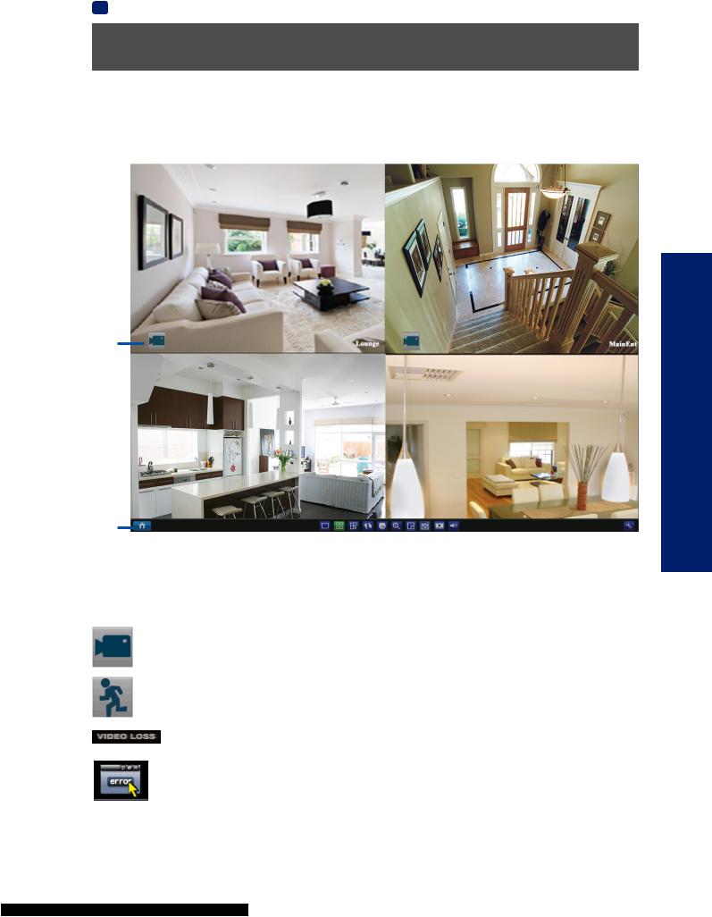
Live View Mode
The Live View Screen
Live View is the default display mode for the DVR. Each camera that’s connected to the DVR will be displayed here. You can check the status and operate your DVR and cameras with the icons and menus on the Live View screen.
Status Icons
BASIC SETUP
Menu Bar
Status Icons
Information on the DVR and camera status is displayed as icons on the Live View screen. Each camera will show its own status icons. Icons are there to give you a quick snippet of what’s going on with your cameras - whether your camera has detected motion or even when your camera is having a connectivity issue. The following is a guide of what each icon represents:
The camera icon indicates that this camera is currently recording. This icon will be the same whether the recording was scheduled, initiated manually or triggered by motion (though the motion icon will also be present if there’s motion detected).
The motion icon indicates that the DVR is detecting motion coming from this camera. It doesn’t necessarily mean it’s recording (the camera icon will be there, too, if that’s the case!).
Video Loss indicates that the channel displaying this has lost the feed from its camera. This may be caused by a disconnected/damaged cable, the camera may have lost power, the camera may have been de-registered from the channel or the video standard might be wrong (PAL/NTSC).
If you see this icon on-screen (it’ll be lurking in the lower right corner by default) it indicates that something has gone wrong. Click the icon to access theEvent Logwhere you’ll get more information about exactly what has gone wrong.
19
 Loading...