


RETAIN THESE INSTRUCTIONS
FOR FUTURE REFERENCE
This appliance may be installed in an aftermarket permanently located, manufactured home (USA only) or mobile home, where not prohibited by local codes. This appliance is only for use with the type of gas indicated on the rating plate. This appliance is not convertible for use with other gases, unless a certified kit is used.
INSTALLATION
INSTRUCTIONS
B-VENT
GHC-5500/6500 AND GRD-5500/6500 SERIES
B-VENTED GAS FIREPLACES
P/N 700,027M REV. E 07/2004
MODELS
Millivolt Electronic
Models Models
|
|
|
|
|
|
|
|
|
GHC-5500N |
GHC-5500NE-2 |
||
|
|
|
|
|
|
|
|
|
GHC-5500P |
GHC-5500PE-2 |
||
|
|
|
|
|
|
|
|
|
GRD-5500N |
GRD-5500NE-2 |
||
|
|
|
|
|
|
|
|
|
GRD-5500P |
GRD-5500PE-2 |
||
|
|
|
|
|
|
|
|
|
GHC-6500N |
GHC-6500EN |
||
|
|
|
|
|
|
|
|
|
GHC-6500P |
GHC-6500EP |
||
|
|
|
|
|
|
|
|
|
GRD-6500N |
GRD-6500EN |
||
|
|
|
|
|
|
|
|
|
GRD-6500P |
GRD-6500EP |
||
|
|
|
|
|
|
|
|
|
|
|
|
|
|
|
|
For GHC/GRD-5500 |
|
|
|
|
|
|
|
|
|
|
|
|
WH Report No. J20046562 |
|
|
|
|
AVERTISSEMENT: ASSUREZ-VOUS DE BIEN SUIVRE |
|
|
||
|
|
|
|
|
|
|
|
|
|
|||
|
|
|
For GHC/GRD-6500 |
|
|
|
|
LESINSTRUCTIONSDONNÉDANSCETTENOTICEPOUR |
|
|
||
|
|
|
WH Report No. J20046564 |
|
|
|
|
RÉDUIRE AU MINIMUM LE RISQUE D'INCENDIE OU |
|
|
||
|
|
|
|
|
|
|
|
|
|
|||
|
|
|
|
|
|
|
|
POUR ÉVITER TOUT DOMMAGE MATÉRIEL, TOUTE |
|
|
||
|
|
|
|
|
|
|
|
BLESSURE OU LA MORT. |
|
|
|
|
|
WARNING:IFTHEINFORMATIONINTHISMANUAL |
|
|
|
|
|
||||||
|
|
|
|
|
|
|
|
|
|
|||
|
IS NOT FOLLOWED EXACTLY, A FIRE OR EXPLO- |
|
|
|
|
POUR VOTRE SÉCURITÉ: Ne pas entreposer ni utiliser |
|
|||||
|
SION MAY RESULT CAUSING PROPERTY DAM- |
|
|
|
|
d'essence ni d'autre vaperurs ou liquides inflammables |
|
|||||
|
AGE, PERSONAL INJURY OR LOSS OF LIFE. |
|
|
|
|
dans le voisinage de cet appareil ou de tout autre |
|
|||||
FOR YOUR SAFETY: Do not store or use gasoline |
|
|
|
appareil. |
|
|
|
|||||
|
|
|
|
|
|
|
|
|||||
or other flammable vapors or liquids in the vicin- |
|
|
|
POUR VOTRE SÉCURITÉ: Que faire si vous sentez une |
|
|||||||
ity of this or any other appliance. |
|
|
|
odeur de gaz: |
|
|
|
|||||
FOR YOUR SAFETY: What to do if you smell gas: |
|
|
|
• Ne pas tenter d'allumer d'appareil. |
|
|||||||
• |
DO NOT light any appliance. |
|
|
|
• Ne touchez à aucun interrupteur. Ne pas vous servir |
|
||||||
|
|
|
|
des téléphones se trouvant dans le batiment où |
|
|||||||
• |
DO NOT touch any electrical switches. |
|
|
|
|
|
||||||
|
|
|
|
vous vous trouvez. |
|
|
|
|||||
• |
DO NOT use any phone in your building. |
|
|
|
|
|
|
|
||||
|
|
|
• |
Evacuez la piéce, le bâtiment ou la zone. |
|
|||||||
• |
Immediately call your gas supplier from a |
|
|
|
|
|||||||
|
|
|
• |
Appeflez immédiatement votre fournisseur de gaz |
|
|||||||
|
|
neighbor’s phone. |
|
|
|
|
||||||
|
|
|
|
|
|
depuis un voisin. Suivez les instructions du |
|
|||||
Follow your gas suppliers instructions. |
|
|
|
|
|
|||||||
|
|
|
|
fournisseur. |
|
|
|
|||||
• If your gas supplier cannot be reached, call the |
|
|
|
|
|
|
|
|||||
|
|
|
• Si vous ne pouvez rejoindre le fournisseur de gaz, |
|
||||||||
|
|
fire department. |
|
|
|
|
||||||
|
|
|
|
|
|
appelez le service dos incendies. |
|
|||||
|
|
|
|
|
|
|
|
|
|
|||
Installation and service must be performed by a |
|
|
|
L'installation et service doit être exécuté par un qualifié |
|
|||||||
qualified installer, service agency or the gas |
|
|
|
|
||||||||
|
|
|
installer, agence de service ou le fournisseur de gaz. |
|
||||||||
supplier. |
|
|
|
|
||||||||
|
|
|
|
|
|
|
1 |
|||||
|
|
|
NOTE: DIAGRAMS & |
|
ILLUSTRATIONS NOT TO SCALE. |
|
|
|||||

TABLE OF CONTENTS |
|
|
Packaging ........................................ |
page |
2 |
Introduction ..................................... |
page |
2 |
General Information ......................... |
page |
2 |
Location .......................................... |
page |
3 |
Appliance Specifications - 5500 ...... |
page |
4 |
Appliance Specifications - 6500 ...... |
page |
5 |
Venting ............................................ |
page |
6 |
Clearances ....................................... |
page |
6 |
Framing Specifications .................... |
page |
6 |
Typical Installation Sequence .......... |
page |
7 |
Pre-Installation Notes ...................... |
page |
7 |
Installation ....................................... |
page |
8 |
Field Wiring ..................................... |
page |
9 |
Connecting Gas Line ........................ |
page |
11 |
Outside Air Kit Installation ............... |
page |
11 |
Log and Rockwool Installation ........ |
page |
12 |
Appliance Operation ........................ |
page |
12 |
Millivolt Appliance Checkout ............ |
page |
12 |
Electronic Appliance Checkout ......... |
page |
13 |
Safety Limit Switch Operation ......... |
page |
13 |
Adjustments .................................... |
page |
14 |
Finishing Requirements ................... |
page |
14 |
Cold Climate Insulation .................... |
page |
16 |
Installation Accessories ................... |
page |
16 |
Gas Conversion Kits .................. |
page 16 |
|
This installation manual will help you obtain a safe, efficient, dependable installation for your appliance and vent system.Please read and understand these instructions before beginning your installation.
PACKAGING
The assembled vented gas fireplace is packaged with:
1- one cartoned log set located in firebox area.
2- one bag of glowing embers (rockwool) located in the bottom compartment.
3- one envelope containing the literature package which consists of the homeowner's manual, installation instructions, and warranty; envelope is located in the control area.
4- wall switch for burner operation taped to top of unit.
INTRODUCTION
The GHC-5500/6500N, P models are circulating system appliances; the GRD-5500/6500N, P models are radiant heat system appliances; both types utilize a millivolt gas control valve and a piezo ignition system. There is no need for an external power source to operate these systems. They are designed to operate on either natural or propane gas.
2
The GHC-5500NE-2, PE-2 and GHC-6500EN, EP models are circulating system appliances; the GRD-5500NE-2, PE-2 and GRD-6500EN, EP models are radiant heat system appliances; both utilize an electronic gas control valve along with an intermittent ignition system.
These systems require an external power source in order to operate. They are designed to operate on either natural or propane gas.
These appliances comply with National Safety Standards and are tested and listed by Warnock Hersey (Report No. J20046562 - for 5500 series; J20046564 - for 6500 series models) to ANSI Z21.50 - 2000 (in Canada, CSA 2.22 - 2000), and CAN/CGA-2.17-M91 in both USA and Canada, as vented gas fireplaces.
Installation must conform to local codes. In the absence of local codes, installation must comply with the current National Fuel Gas Code, ANSI Z223.1 (NFPA 54). (In Canada, the current CAN/CGA B149 installation code.) Electrical wiring must comply with local codes. In the absence of local codes, installation must be in accordance with the National Electrical Code, NFPA 70 - (latest edition). (In Canada, the current CSA C22.1 Canadian Electric Code.)
DO NOT ATTEMPT TO ALTER OR MODIFY THE CONSTRUCTION OF THE APPLIANCE OR ITS COMPONENTS. ANY MODIFICATION OR ALTERATION MAY VOID THE WARRANTY, CERTIFICATION AND LISTINGS OF THIS UNIT.
WARNING: IMPROPER INSTALLATION, ADJUSTMENT, ALTERATION, SERVICE OR MAINTENANCE CAN CAUSE INJURY OR PROPERTY DAMAGE. REFER TO THIS MANUAL. FOR ASSISTANCE OR ADDITIONAL INFORMATION CONSULT A QUALIFIED INSTALLER, SERVICE AGENCY OR THE GAS SUPPLIER.
GENERAL INFORMATION
Note: Installation and repair should be performed by a qualified service person. The appliance should be inspected annually by a qualified professional service technician. More frequent inspections and cleanings may be required due to excessive lint from carpeting, bedding material, etc. It is imperative that the control compartment, burners and circulating air passage ways of the appliance be kept clean.
S'assurer que le brùleur et le compartiment des commandes sont propres. Voir les instructions d'installation et d'utilisation qui accompagnent l'apareil.
NOTE: DIAGRAMS & ILLUSTRATIONS NOT TO SCALE.
Provide adequate clearances around air openings and adequate accessibility clearance for service and proper operation. Never obstruct the front openings of the appliance.
WARNING: THESE FIREPLACES ARE VENTED DECORATIVE GAS APPLIANCES. DO NOT BURN WOOD OR OTHER MATERIAL IN THESE APPLIANCES.
These appliances are designed to operate on natural or propane gas only. The use of other fuels or combination of fuels will degrade the performance of this system and may be dangerous.
For elevations of 0-2000 ft. (0-610 m.) the GHC/GRD-5500 input is 24,000 BTU/HR for both natural and propane gases, the GHC/ GRD-6500 input is 27,000 BTU/HR for both natural and propane gases.
Table 1 shows the units' factory-installed gas orifice size for installations at elevations of 0-2000 feet (0-610 meters).
GHC |
Orifice size |
Elevation |
|
GRD |
|
|
Feet |
Series |
Nat. |
Prop. |
(meters) |
|
|
||
|
|
|
|
5500 |
#43 |
#54 |
0-2000 |
|
|
|
|
6500 |
#41 |
#53 |
(0-610) |
|
|||
|
|
|
|
Table 1
Table 2 shows the units' gas orifice size for installations at elevations greater than 2000 ft. (0-610 m.). These orifices must be ordered separatelyusingthekitnumberslistedintable2.
GHC |
Orifice size |
Elevation |
||
(Kit Number) |
||||
GRD |
Feet |
|||
|
|
|||
Series |
Nat. |
Prop. |
(meters) |
|
|
|
|||
|
|
|
|
|
5500 |
#44 |
#55 |
greater |
|
(040611) |
(040612) |
|||
|
than |
|||
|
|
|
||
6500 |
#43 |
#55 |
2000 |
|
(610) |
||||
(051916) |
(051917) |
|||
|
|
|||
|
|
|
|
|
Table 2
Nominal operating pressures for the manifold side of the gas control system are; 3.5 inches water column (6.54 MmHg) for natural gas models and 10 inches water column (18.69 MmHg) for propane gas models.

Do not use these appliances if any part has been under water. Immediately call a qualified, professional service technician to inspect the appliance and to replace any parts of the control system and any gas control which have been under water.
Ne pas se servir de cet appareil s'il a été plongé dans l'eau, complètement ou en partie. Appeler un technicien qualifié pour inspecter l'appareil et remplacer toute partie du système de contrôle et toute commande qui ont été plongés dans l'lau.
This appliance may be installed in an aftermarket permanently located, manufactured home (USA only) or mobile home, where not prohibited by local codes. This appliance is only for use with the type of gas indicated on the rating plate. This appliance is not convertible for use with other gases, unless a certified kit is used.
Cet appareil peut être installé dans un maison préfabriquée (É.-U. seulement) ou mobile déjà installée à demeure si les réglements locaux le permettent.
Cet appareil doit être utilisé uniquement avec les types de gaz indiqués sur la plaque signalétique. Ne pas l'utiliser avec d'autres gaz sauf si un kit de conversion certifié est installé.
Millivolt appliances may be fitted at time of manufacture with either a Robertshaw millivolt gas control valve or Robertshaw electronic gas control valve. Both valves have been tested with and approved for use with these appliances and are listed accordingly.
A ¹⁄ " NPT test gage connection is provided on either gas control valve adjacent to the outlet to the main burner.
Minimum inlet gas pressure to the appliance is 4.5 inches water column (1.12 kPa) for natural gas and 11 inches water column (2.74 kPa) for propane for the purpose of input adjustment.
Maximum inlet gas supply pressure to the appliance is 10.5 inches water column (2.61 kPa) for natural gas and 13.0 inches water column (3.23 kPa) for propane.
The appliance must be isolated from the gas supply piping system (by closing its individual manual shut-off valve) during any pressure testing of the gas supply piping system at test pressures equal to or less than ¹⁄ psig (3.5) kPa).
The appliance and its individual shut-off valve must be disconnected from the gas supply piping system during any pressure testing of that system at pressures in excess of ¹⁄ psig (3.5 kPa).
These appliances must not be connected to a chimney or flue serving a separate solid fuel burning appliance.
Do not place clothing or other materials on or near this appliance.
WARNING: FAILURE TO COMPLY WITH THE INSTALLATION AND OPERATING INSTRUCTIONS PROVIDED IN THIS DOCUMENT WILL RESULT IN AN IMPROPERLY INSTALLED AND OPERATING APPLIANCE, VOIDING ITS WARRANTY. ANY CHANGE TO THIS APPLIANCE AND/OR ITS OPERATING CONTROLS IS DANGEROUS. IMPROPER INSTALLATION OR USE OF THIS APPLIANCE CAN CAUSE SERIOUS INJURY OR DEATH FORM FIRE, BURNS, EXPLOSION OR CARBON MONOXIDE POISONING.
Carbon Monoxide Poisoning: Early signs of carbon monoxide poisoning are similar to the flu with headaches, dizziness and/or nausea. If you have these signs, obtain fresh air immediately. Turn off the gas supply to the appliance and have it serviced by a qualified professional, as it may not be operating correctly.
WARNING: B-VENT APPLIANCES ARE NOT DESIGNED TO OPERATE IN NEGATIVELY PRESSUREDENVIRONMENTS(PRESSURE WITHIN THE HOME IS LESS THAN PRESSURES OUTSIDE). SIGNIFICANT NEGATIVELY PRESSURED ENVIRONMENTS CAUSED BY WEATHER, HOME DESIGN, OR OTHER DEVICES MAY IMPACT THE OPERATION OF THESE APPLIANCES. NEGATIVE PRESSURES MAY RESULT IN POOR FLAME APPEARANCE, SOOTING, DAMAGE TO PROPERTY AND/OR SEVERE PERSONAL INJURY. DO NOT OPERATE THESEAPPLIANCESINNEGATIVELYPRESSURED ENVIRONMENTS.
WARNING: CHILDREN AND ADULTS SHOULD BE ALERTED TO THE HAZARDS OF HIGH SURFACE TEMPERATURES. USE CAUTION AROUND THE APPLIANCE TO AVOID BURNS OR CLOTHING IGNITION. YOUNG CHILDREN SHOULD BE CAREFULLY SUPERVISED WHEN THEY ARE IN THE SAME ROOM AS THE APPLIANCE.
WARNING: DO NOT PLACE CLOTHING OR OTHER FLAMMABLE MATERIALS
ON OR NEAR THIS APPLIANCE.
NOTE: DIAGRAMS & ILLUSTRATIONS NOT TO SCALE.
AVERTISSEMENT: SURVEILLER LES ENFANTS. GARDER LES VÊTEMENTS, LES MEUBLES, L'ESSENCE OU AUTRES LIQUIDES À VAPEUR INFLAMMABLES LIN DE L'APPAREIL.
WARNING: THIS APPLIANCE MAY ONLY BE FITTED WITH DOORS CERTIFIED FOR USE WITH THE APPLIANCE.
AVERTISSEMENT: POUR UTILISATION UNIQUEMENT AVEC LES PORTES EN VERRE CERTIFIÊES AVEC L'APPAREIL.
These appliances are equipped with an integral combustion air door and actuator arm. Combustion air kits are optional. Install as shown in step 7 on page 11.
LOCATION
Typical Locations
Figure 1
In selecting the location, the aesthetic and functional use of the appliance are primary concerns. However, vent system routing to the exterior and access to the fuel supply are also important. Due to high temperatures the appliance should be located out of traffic and away from furniture and draperies. Consideration should be given to traffic ways, furniture, draperies, etc., due to elevatedsurfacetemperatures.Thelocationshould also be free of electrical, plumbing or other heating/air conditioning ducting.
The appliance should be mounted on a fully supported base extending the full width and depth of the unit. The appliance may be located on or near conventional construction materials. However, if installed on combustible materials, such as carpeting, vinyl tile, etc., a metal or wood barrier covering the entire bottom surface must be used.
These appliances may be used for bedroom installations in the United States and are listed accordingly. These units may not be installed in bedrooms in Canada.
3
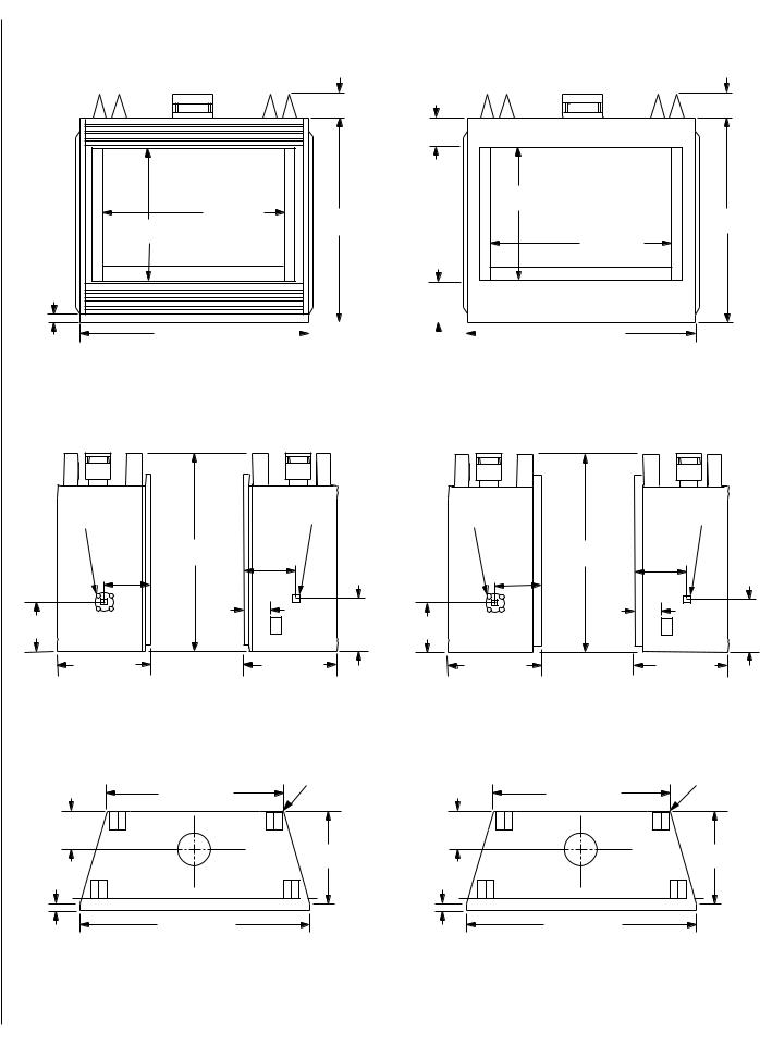
APPLIANCE SPECIFICATIONS GHC/GRD-5500
GHC-5500 |
GRD-5500 |
4 ¹⁄ " |
4 ¹⁄ " |
(108 mm) |
(108 mm) |
|
|
6 ¹⁄ " |
|
|
(165 mm) |
|
|
21" |
33 ¹⁄ " |
|
(533 mm) |
(845 mm) |
34 ¹⁄ " |
34 ¹⁄ " |
21" |
(876 mm) |
(876 mm) |
(533 mm) |
|
33 ¹⁄ " |
|
|
(845 mm) |
1 ¹⁄ " |
|
|
(38 mm) |
|
7 " |
|
|
(178 mm) |
35 ⁄ " (911 mm) |
|
|
|
|
|
|
|
|
35 ⁄ " (911 mm) |
|
|
|
|
|
|
|
|
||
|
|
|
|
|
|
|
|
||
Front View |
|
|
|
|
|
|
Front View |
||
Combustion |
|
Gas Inlet |
Combustion |
|
Gas Inlet |
Air Inlet |
|
Line |
Air Inlet |
|
Line |
|
38 ³⁄ " |
10 " |
|
38 ³⁄ " |
9 " |
10 ¹⁄ " |
(984 mm) |
(254 mm) |
9 ¹⁄ " |
(984 mm) |
(229 mm) |
(267 mm) |
|
|
(241 mm) |
|
|
|
4 ¹⁄ " |
8 ¹⁄ " |
|
4 ¹⁄ " |
8 ¹⁄ " |
8 ¹⁄ " |
(114 mm) |
8 ¹⁄ " |
(114 mm) |
||
(216 mm) |
|
(216 mm) |
(216 mm) |
|
(216 mm) |
|
|
|
|
||
16" (406 mm) |
|
16" (406 mm) |
15" (381 mm) |
|
15" (381 mm) |
Left View |
|
Right View |
Left View |
|
Right View |
|
Top Spacers (4) |
Top Spacers (4) |
|
27 ³⁄ " (705 mm) |
27 ³⁄ " (705 mm) |
|
6 ¹⁄ " |
6 ¹⁄ " |
|
(165 mm) |
(165 mm) |
|
15 " |
15 " |
|
(381 mm) |
(381 mm) |
|
1" |
1" |
|
(25.4 mm) |
(25.4 mm) |
|
35 ⁄ " (911 mm) |
35 ⁄ " (911 mm) |
|
Top View |
Top View |
|
Figure 2 |
|
4 |
NOTE: DIAGRAMS & ILLUSTRATIONS NOT TO SCALE. |
|

APPLIANCE SPECIFICATIONS GHC/GRD-6500
GHC-6500 |
GRD-6500 |
4 ¹⁄ " |
4 ¹⁄ " |
(108 mm) |
(108 mm) |
6 ³⁄ " |
|
|
|
6 ¹⁄ " |
|
(162 mm) |
|
|
|
(165 mm) |
|
21 ¹⁄ " |
|
|
|
21" |
|
(546 mm) |
|
|
|
(533 mm) |
|
32" (813 mm) |
36 |
¹⁄ " |
16 ¹⁄ " |
36 ¹⁄ " |
|
21" |
|
||||
(533 mm) |
³⁄ " (959 mm) |
(921 mm) |
(413 mm) |
(921 mm) |
|
37 |
|
|
32" (813 mm) |
|
|
16 ¹⁄ " |
|
|
|
|
|
(413 mm) |
|
|
|
37 ³⁄ " (959 mm) |
|
39 ⁄ " (1013 mm) |
|
|
|
||
|
|
|
|
||
1 ¹⁄ " |
|
|
|
|
|
(38 mm) |
|
|
|
8 ³⁄ " |
|
|
|
|
|
(222 mm) |
|
40 ⁄ " (1032 mm) |
|
|
40 ⁄ " (1032 mm) |
|
|
Front View |
Front View |
¹⁄ " |
|
Nailing |
Nailing |
|
¹⁄ " |
|
(13 mm) |
|
|
(13 mm) |
|||
Combustion |
Flange |
Flange |
|
|||
Spacer |
Gas Inlet |
Spacer |
||||
|
|
|||||
|
Air Inlet |
|
|
|
||
|
|
|
|
Line |
|
|
|
|
40 ¹⁄ " |
|
|
||
|
7 ¹⁄ " |
(1029 mm) |
|
|
||
|
|
|
6 ¹⁄ " |
|
||
|
(191 mm) |
|
|
|
||
|
|
|
|
(165 mm) |
|
|
|
|
|
4 ¹⁄ " |
|
|
|
10 ¹⁄ " |
|
|
(105 mm) |
|
|
|
(267 mm) |
6 ¹⁄ " |
5" |
|
|
5" |
|
|
(165 mm) |
(127 mm) |
|
|
(127 mm) |
|
|
20" (508 mm) |
|
|
17 ⁄ " |
|
|
|
|
|
|
(454 mm) |
|
|
|
Left View |
|
|
Right View |
|
|
¹⁄ " |
|
Nailing |
Nailing |
|
¹⁄ " |
(13 mm) |
Combustion |
Flange |
Flange |
|
(13 mm) |
Spacer |
|
|
Gas Inlet |
Spacer |
|
|
Air Inlet |
|
|
|
|
|
|
|
Line |
|
|
|
|
|
|
|
|
|
|
40 ¹⁄ " |
|
|
|
|
7 ¹⁄ " |
(1029 mm) |
|
|
|
|
|
|
6 ¹⁄ " |
|
|
|
(191 mm) |
|
|
|
|
|
|
|
|
(165 mm) |
|
|
|
|
4 ¹⁄ " |
|
|
10 ¹⁄ " |
|
|
(105 mm) |
|
|
(267 mm) |
6 ¹⁄ " |
5" |
|
|
5" |
|
(165 mm) |
(127 mm) |
|
|
(127 mm) |
|
19" (483 mm) |
|
|
17 ⁄ " |
|
|
|
|
|
(454 mm) |
|
|
Left View |
|
|
Right View |
|
|
|
Top Spacers (4) |
|
Top Spacers (4) |
|
31" (787 mm) |
|
31" (787 mm) |
|
7 ³⁄ " |
¹⁄ " |
7 ³⁄ " |
¹⁄ " |
|
(197 mm) |
(197 mm) |
|
||
|
(13 mm) |
|
(13 mm) |
|
|
Spacer ¹⁄ " |
17 ⁄ " |
Spacer ¹⁄ " |
17 ⁄ " |
|
(13 mm) |
(454 mm) |
(13 mm) |
(454 mm) |
1" |
|
⁄ " |
|
|
|
(16 mm) |
|
|
|
(25.4 mm) |
|
|
|
|
|
|
|
|
|
|
40 ⁄ " (1032 mm) |
1 ⁄ " |
40 ⁄ " (1032 mm) |
|
|
|
|
|
|
|
Top View |
(41 mm) |
Top View |
|
|
|
|
||
Figure 3 |
|
|
|
|
|
|
NOTE: DIAGRAMS & ILLUSTRATIONS NOT TO SCALE. |
|
5 |

Venting
Gas Vent Rule – Gas vent caps are not permitted within 8 feet (2.4 mm) of a vertical wall or similar obstruction. Gas vent caps that are located 8' or more from a portion of a building which extends at an angle greater than 45° upward from the horizontal may terminate in accordance with the table in Figure 4, provided that in no case shall any discharge opening on the cap be less than 2' (610 mm) horizontally from the roof surface (National Fuel Gas Code ANSI Z223.1 (NFPA 54) 7.6.2) (CAN/CGA B149).
X
12
Roof Pitch is X/12
Minimum Height from Roof to Lowest Discharge Opening
|
Minimum Height |
|
Roof Slope |
from Roof to Lowest |
|
Discharge Opening |
||
|
|
|
|
Feet |
Meters |
Flat to 6/12 |
1' 0" |
0.3 |
Over 7/12 to 9/12 |
2' 0" |
0.6 |
Over 10/12 to 12/12 |
4' 0" |
1.2 |
Over 13/12 to 16/12 |
6' 0" |
1.8 |
|
|
|
Over 17/12 to 21/12 |
8' 0" |
2.4 |
|
|
|
Note: Venting terminals shall not be recessed into a wall or siding.
Figure 4
6
APPLIANCE CLEARANCES
|
GHC/GRD-5500 |
GHC/GRD-6500 |
|
|
|
|
|
Back |
1/2 in. (13mm) |
1/2 in. (13mm) |
|
|
0 in. (0 mm) to spacers |
||
|
|
||
|
|
|
|
Sides |
1/2 in. (13mm)** |
1/2 in. (13mm)** |
|
|
0 in. (0 mm) to spacers |
||
|
|
||
|
|
|
|
Top Spacers |
0 in. (0 mm) |
||
|
|
|
|
Floor |
0 in. (0 mm) |
||
|
|
|
|
*From |
|
|
|
Bottom of |
65 1/2 in. (1664 mm) |
67 1/2 in. (1715 mm) |
|
Unit to |
|||
|
|
||
Ceiling |
|
|
|
|
|
|
|
Vent |
1 in. (25.4 mm) |
||
|
|
|
|
|
SERVICE CLEARANCE |
||
|
|
|
|
Front |
3 Feet (0.9 meters) |
||
|
|
|
|
* Note: See also Figure 32 on page 14 for an illustration of this clearance, for clearances to a sidewall and for mantel clearances.
**Note: The nailing tabs and the area directly behind the nailing tabs are exempt from the clearances described in the above table. See Figure 9 on page 8.
Table 3
FRAMING SPECIFICATIONS
Use Only 2x4 or Larger
Lumber
Header
E
D
A
*C
Note: If the Outside Combustion Air Kit is to be installed, it must be installed before the appliance is framed and enclosed in the finishing walls.
B
Gas Supply Line
Left or Right Side - 5500
Right Side Only - 6500
*Note: The framed depth - dimension “C”- from a framed wall, must always be measured from a finished surface. If a wall covering such as drywall is to be attached to the rear wall, then dimension “C” must be measured from the drywall surface. It is important that this dimension be exact.
|
Model No. |
|
A |
B |
C |
D |
E |
|
|
|
|
|
|
|
|
|
|
|
GHC/GRD-5500 |
in. |
33 1/4 |
38 3/4 |
15 1/2 |
8 1/2 |
8 1/2 |
|
|
|
|
|
|
|
|
||
|
mm |
845 |
984 |
394 |
216 |
216 |
||
|
|
|||||||
|
|
|
|
|
|
|
|
|
|
GHC/GRD-6500 |
in. |
40 3/4 |
40 3/4 |
18 |
6 1/2 |
5 |
|
|
|
|
|
|
|
|
||
Figure 5 |
mm |
1035 |
1035 |
457 |
165 |
127 |
||
|
||||||||
|
|
|
|
|
|
|
||
NOTE: DIAGRAMS & ILLUSTRATIONS NOT TO SCALE. |
|
|
|
|
|
|||
 Loading...