


Superior CDST-CMP, CDPF-CEP, CDST-CEP, CDCR-CEN, CDST-CMN User Manual
...
|
|
|
|
|
|
|
|
|
|
|
|
INSTALLATION |
|
|
|
|
|
|
|
|
|
|
|
|
|
|
|
|
|
|
INSTRUCTIONS |
|
|
|
|
|
|
|
|
|
|
|
|
|
|
|
|
|
|
|
|
|
|
|
|
|
|
|
|
|
|
|
|
|
|
|
|
|
|
|
|
|
|
|
|
|
|
|
|
|
|
|
|
|
|
|
|
DIRECT VENT |
|
|
|
|
|
|
|
|
|
|
|
|
|
|
|
|
|
|
MULTI-OPEN SERIES |
||||||
|
|
This appliance may be installed in an aftermar- |
|
|
|
|
|
|||||||||||
|
|
|
|
|
|
|
|
|
|
|
|
|
|
|||||
|
|
ket permanently located, manufactured home |
|
|
|
|
|
VENTED GAS FIREPLACE HEATERS - DIRECT VENT MODELS |
||||||||||
|
|
(USA only) or mobile home, where not prohib- |
|
|
|
|
|
P/N 700,001M REV. H 09/2005 |
|
|
|
|
|
|
||||
|
|
ited by local codes. This appliance is only for |
|
|
|
|
|
MODELS |
|
|
|
|
|
|
||||
|
|
use with the type of gas indicated on the rating |
|
|
|
|
|
|
|
|
|
|
|
|||||
|
|
plate. This appliance is not convertible for use |
|
|
|
|
|
Millivolt Models |
Electronic Models |
|||||||||
|
|
with other gases, unless a certified kit is used. |
|
|
|
|
|
|||||||||||
|
|
|
|
|
|
|
CDST-CMN CDCL-CMN |
CDST-CEN |
CDCL-CEN |
|||||||||
|
|
|
|
|
|
|
|
|
|
|
|
|||||||
|
|
|
|
|
|
|
|
|
|
|
|
|||||||
|
|
|
|
|
|
|
|
|
|
|
|
CDST-CMP CDCL-CMP |
CDST-CEP |
CDCL-CEP |
||||
|
|
|
|
|
|
|
|
|
|
|
|
|||||||
|
|
WARNING:IFTHEINFORMATIONINTHISMANUAL |
|
|
|
|
|
|
CDPF-CMN CDCR-CMN |
CDPF-CEN |
CDCR-CEN |
|||||||
|
|
IS NOT FOLLOWED EXACTLY, A FIRE OR EXPLO- |
|
|
|
|
|
|
CDPF-CMP CDCR-CMP |
CDPF-CEP |
CDCR-CEP |
|||||||
|
|
SION MAY RESULT CAUSING PROPERTY DAM- |
|
|
|
|
|
|
|
|
|
|
|
|
|
|||
|
|
AGE, PERSONAL INJURY OR LOSS OF LIFE. |
|
|
|
|
|
|
RETAIN THESE INSTRUCTIONS |
|||||||||
|
|
|
|
|
|
|
|
|
|
|
|
FOR FUTURE REFERENCE |
|
|
|
|
|
|
|
|
FOR YOUR SAFETY: Do not store or use gasoline |
|
|
|
|
|
|
|
|
|
|
||||||
|
|
|
|
|
|
|
|
|
|
|
|
|
|
|||||
|
|
or other flammable vapors or liquids in the vicin- |
|
|
|
|
|
|
|
|
|
|
|
|
||||
|
|
|
|
|
AVERTISSEMENT: ASSUREZ-VOUS DE BIEN SUIVRE |
|
|
|
|
|||||||||
|
|
ity of this or any other appliance. |
|
|
|
|
|
|
|
|
||||||||
|
|
|
|
|
|
LESINSTRUCTIONSDONNÉDANSCETTENOTICEPOUR |
|
|
|
|
||||||||
|
|
|
|
|
|
|
|
|
|
|
|
|
|
|
||||
|
|
FOR YOUR SAFETY: What to do if you smell gas: |
|
|
|
|
RÉDUIRE AU MINIMUM LE RISQUE D'INCENDIE OU |
|
|
|
|
|||||||
|
|
|
|
|
|
|
|
|
|
|
POUR ÉVITER TOUT DOMMAGE MATÉRIEL, TOUTE |
|
|
|
|
|||
|
|
• DO NOT light any appliance. |
|
|
|
|
BLESSURE OU LA MORT. |
|
|
|
|
|
|
|||||
|
|
• |
DO NOT touch any electrical switches. |
|
|
|
|
POUR VOTRE SÉCURITÉ: Ne pas entreposer ni utiliser |
|
|
|
|||||||
|
|
• |
DO NOT use any phone in your building. |
|
|
|
|
|
|
|
||||||||
|
|
|
|
|
|
d'essence ni d'autre vapeurs ou liquides inflammables |
|
|
|
|||||||||
|
|
• |
Immediately call your gas supplier from a |
|
|
|
|
|
|
|
||||||||
|
|
|
|
|
|
dans le voisinage de cet appareil ou de tout autre |
|
|
|
|||||||||
|
|
|
neighbor’s phone. Follow your gas suppliers |
|
|
|
|
|
|
|
||||||||
|
|
|
|
|
|
|
appareil. |
|
|
|
|
|
|
|||||
|
|
|
instructions. |
|
|
|
|
|
|
|
|
|
|
|||||
|
|
|
|
|
|
|
|
|
|
|
|
|
|
|
||||
|
|
• If your gas supplier cannot be reached, call the |
|
|
|
|
POUR VOTRE SÉCURITÉ: Que faire si vous sentez une |
|
|
|
||||||||
|
|
|
fire department. |
|
|
|
|
|
|
|
||||||||
|
|
|
|
|
|
|
odeur de gaz: |
|
|
|
|
|
|
|||||
|
|
|
|
|
|
|
|
|
|
|
|
|
|
|
|
|
||
|
|
Installation and service must be performed by a |
|
|
|
|
• |
Ne pas tenter d'allumer d'appareil. |
|
|
|
|
|
|||||
|
|
qualified installer, service agency or the gas |
|
|
|
|
|
|
|
|
|
|||||||
|
|
|
|
|
|
• Ne touchez à aucun interrupteur. Ne pas vous servir |
|
|
|
|||||||||
|
|
supplier. |
|
|
|
|
|
|
|
|||||||||
|
|
|
|
|
|
|
des téléphones se trouvant dans le batiment où |
|
|
|
||||||||
|
|
|
|
|
|
|
|
|
|
|
|
|
|
|
||||
|
|
|
|
|
|
|
|
|
|
|
|
vous vous trouvez. |
|
|
|
|
|
|
|
|
|
|
|
|
|
|
|
|
|
• |
Evacuez la piéce, le bâtiment ou la zone. |
|
|
|
|||
|
|
|
|
|
|
|
|
|
|
|
• |
Appelez immédiatement votre fournisseur de gaz |
|
|
|
|||
|
|
|
|
|
WH Report No. J20006712 |
|
|
|
|
|
|
depuis un voisin. Suivez les instructions du |
|
|
|
|||
|
|
|
|
|
|
|
|
|
|
|
|
fournisseur. |
|
|
|
|
|
|
|
|
|
|
|
|
|
|
|
|
|
|
|
|
|
|
|
|
|
|
|
|
|
|
|
|
|
|
|
|
• Si vous ne pouvez rejoindre le fournisseur de gaz, |
|
|
|
||||
A French manual is available upon request. Order Form Number |
|
|
|
|
|
appelez le service dos incendies. |
|
|
|
|
|
|||||||
|
|
|
|
|
|
|
|
|
|
|
|
|||||||
700,001CF. |
|
|
|
|
L'installation et service doit être exécuté par un qualifié |
|
|
|
||||||||||
|
|
|
|
|
|
|
|
|
|
|
|
|
|
|||||
Ce manuel d’installation est disponible en francais, simplement |
|
|
|
|
installeur, agence de service ou le fournisseur de gaz. |
|
|
|
||||||||||
en faire la demande. Numéro de la pièce 700,001CF.NOTE: DIAGRAMS & |
|
ILLUSTRATIONS NOT TO SCALE. |
|
|
|
|
1 |
|||||||||||
|
|
|
||||||||||||||||
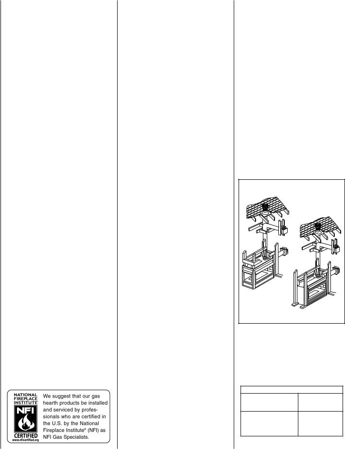
TABLE OF CONTENTS |
|
|
|
Packaging ........................................ |
page |
2 |
|
Introduction ..................................... |
page |
2 |
|
General Information ......................... |
page |
2 |
|
Location |
.......................................... |
page |
3 |
Appliance and Vent Clearances ....... |
page |
4 |
|
Vent Termination Clearances ........... |
page |
4 |
|
Typical Installation Sequence .......... |
page |
5 |
|
Detailed Installation Steps ............... |
page |
5 |
|
Step 1. |
Framing ............................. |
page |
5 |
Fireplace Specifications ................... |
page |
8 |
|
Step 2. Routing Gas Line ............... |
page |
10 |
|
Step 3. Install the Venting System . page |
10 |
||
Vertical Termination Systems .......... |
page |
11 |
|
Vent Section Length Chart ............... |
page |
11 |
|
Vertical Vent Tables and Figures ...... |
page |
14 |
|
Horizontal Termination System ........ |
page |
16 |
|
Horizontal Vent Tables and Figures . page |
18 |
||
Venting Using Flexible Vent Pipe ..... |
page |
21 |
|
Step 4. |
Field Wiring ....................... |
page |
22 |
Step 5. Optional Blower Kit Wiring |
page |
22 |
|
Step 6. Connecting Gas Line .......... |
page |
23 |
|
Step 7. Installing Logs, Decorative Volcanic |
|||
Stone and Glowing Embers ........... |
page |
23 |
|
Step 8. |
Checking Unit Operation ..... |
page |
23 |
Step 9. |
Installing Glass |
|
|
Enclosure Panels ........................... |
page |
24 |
|
Step 10. Burner Adjustments ........... |
page |
24 |
|
Step 11. Hood Installation ............... |
page |
25 |
|
Finishing Requirements ................... |
page |
25 |
|
Cold Climate Insulation .................... |
page |
25 |
|
Installation Accessories ................... |
page |
26 |
|
Gas Conversion Kits .................. |
page 28 |
||
This installation manual will help you achieve a safe, efficient and dependable installation for your appliance and vent system. Please read and understand these instructions before beginning your installation.
DO NOT ATTEMPT TO ALTER OR MODIFY THE CONSTRUCTION OF THE APPLIANCE OR ITS COMPONENTS. ANY MODIFICATION OR ALTERATION MAY VOID THE WARRANTY, CERTIFICATION AND LISTINGS OF THIS UNIT.
2
PACKAGING
The assembled vented gas fireplace heater is packaged with:
1- one cartoned log set located in firebox area; decorative volcanic stone and glowing embers (rockwool) located inside the bottom cabinet compartment.
2- one envelope containing the literature package which consists of the homeowner's manual, installation instructions, warranty, and 8 (CDST), 4 (CDPF, CDCR and CDCL) nailing flanges; envelope is located on top of the unit.
3- one vent restrictor to be applied as shown on page 10 ; restrictor is taped to the envelope.
4- two hoods (CDST, CDCR, CDCL), or three hoods (CDPF) taped to the top of the fireplace.
INTRODUCTION
These fireplaces are designed, tested and listed for operation and installation with, and only with, Secure Vent™ Direct Vent System Components, Secure Flex™ Flexible Vent Components manufactured by Security Chimneys International and Z-Flex™ Model GA Venting Systems, listed to UL1777 and ULCS635 manufactured by Flexmaster Canada Limited. These approved vent system components are labeled for identification. DO NOT use any other manufacturer's vent components with these appliances.
The millivolt appliances are designed to operate on either natural or propane gas. A millivolt gas control valve with piezo ignition system provides safe, efficient operation. If any optional accessories which require electrical power are being installed, the electrical power must be provided at the time of appliance installation.
Electronic appliances are designed to operate on natural or propane gas. An electronic intermittent pilot ignition system provides safe, efficient operation. External electrical power is required to operate these units.
These appliances comply with National Safety Standards and are tested and listed by Warnock Hersey (Report No. J20006712) to ANSI Z21.88-2000 (in Canada, CSA-2.33-2000), and CAN/CGA-2.17-M91 in both USA and Canada, as vented gas fireplace heaters.
Both millivolt and electronic versions of these appliances are listed by Warnock Hersey for installation in bedrooms and mobile homes.
Installation must conform to local codes. In the absence of local codes, installation must comply with the current National Fuel Gas Code, ANSI Z223.1. (In Canada, the current CAN-1 B149 installation code.) Electrical wiring must comply with the National Electrical Code ANSI/ NFPA 70 - (latest edition). (In Canada, the
current CSA C22-1 Canadian Electrical Code.)
NOTE: DIAGRAMS & ILLUSTRATIONS NOT TO SCALE.
GENERAL INFORMATION
Note: Installation and repair should be performed by a qualified service person. The appliance should be inspected annually by a qualified professional service technician. More frequent inspections and cleanings may be required due to excessive lint from carpeting, bedding material, etc. It is imperative that the control compartment, burners and circulating air passage ways of the appliance be kept clean.
S'assurer que le brùleur et le compartiment des commandes sont propres. Voir les instructions d'installation et d'utilisation qui accompagnent l'appareil.
Provide adequate clearances around air openings and adequate accessibility clearance for service and proper operation. Never obstruct the front, back and/or side viewing surfaces of the appliance.
These appliances are designed to operate on natural or propane gas only.
TYPICAL INSTALLATION |
CDPF |
CDST |
Figure 1 |
Millivolt Models -
Millivolt models come standard with the manually-modulated gas valve; flame appearance and heat output can be controlled at the gas valve.
Input of millivolt models is shown in the following table:
Millivolt Models
Natural and Propane
Input rate (BTU/H)
Gas Models
Manuallymodulated
CDST-CMN, CDPF-CMN,
CDCL-CMN, CDCR-CMN,
30,000 TO 37,500
CDST-CMP, CDPF-CMP,
CDCL-CMP, CDCR-CMP
NOTE: DIAGRAMS & ILLUSTRATIONS NOT TO SCALE.

Electronic Models -
Electronic models have a fixed rate gas valve. Input of electronic models is shown in the following table:
Electronic |
Models |
|
Natural and Propane |
|
Input rate (BTU/H) |
Gas Models |
|
Fixed Rate |
CDST-CEN, CDPF-CEN, |
|
|
CDCL-CEN, CDCR-CEN, |
|
37,500 |
CDST-CEP, CDPF-CEP, |
|
|
|
|
|
CDCL-CEP, CDCR-CEP |
|
|
All Models -
Maximum manifold pressure is 3.5 in. w.c. (0.87 kPa) for natural gas and 10 in. w.c. (2.49 kPa) for LP/Propane gas.
Installations at Altitudes of 0 to 4500 ft.- Units are tested and approved for elevations of 0 to 4500 feet (0 to 1372 meters).
Installations at Altitudes above 4500 ft.- For elevations above 4500 feet (1372 meters), install the unit according to the regulations of the local authorities having jurisdiction and, in the USA, the latest edition of the National Fuel Gas Code (ANSI Z223.1) or, in Canada, the latest edition of the CAN1-B149.1 and .2 codes.
Table 1 shows the units' gas orifice size for the elevations indicated.
Model |
Orifice size* |
Elevation |
||
No. |
|
|
Feet (meters) |
|
Nat. |
Prop. |
|||
|
|
|||
|
|
|
|
|
CDST |
|
|
|
|
CDPF |
#44 |
#55 |
0-4500 |
|
CDCR |
(0-1370 ) |
|||
|
|
|||
CDCL |
|
|
|
|
|
|
|
|
|
* Each model has two burners. Each burner contains one of these orifices.
Table 1
The millivolt appliances are manually controlled and feature a spark ignitor (piezo) that allows the appliance's pilot gas to be lit without the use of matches or batteries. This system will still function in the event of a power outage.
Do not use these appliances if any part has been under water. Immediately call a qualified, professional service technician to inspect the appliance and to replace any parts of the control system and any gas control which have been under water.
Ne pas se servir de cet appareil s'il a été plongé dans l'eau, complètement ou en partie. Appeler un technicien qualifié pour inspecter l'appareil et remplacer toute partie du système de contrôle et toute commande qui ont été plongés dans l'eau.
This appliance may be installed in an aftermarket permanently located, manufactured home (USA only) or mobile home, where not prohibited by local codes. This appliance is only for use with the type of gas indicated on the rating plate. This appliance is not convertible for use with other gases, unless a certified kit is used.
Cet appareil peut être installé dans un maison préfabriquée (É.-U. seulement) ou mobile déjà installée à demeure si les réglements locaux le permettent. Cet appareil doit être utilisé uniquement avec les types de gaz indiqués sur la plaque signalétique. Ne pas l'utiliser avec d'autres gaz sauf si un kit de conversion certifié est installé.
Test gage connections are provided on the front of the millivolt gas control valve (identified IN for the inlet and OUT for the manifold side). A ¹⁄ " NPT test gage connection is provided at the inlet and outlet side of the electronic gas control valve.
Minimum inlet gas pressure to these appliances is 5.0 inches water column (1.24 kPa) for natural gas and 11.0 inches water column (2.74 kPa) for propane for the purpose of input adjustment.
Maximum inlet gas supply pressure to these appliances is 10.5 inches water column (2.61 kPa) for natural gas and 13.0 inches water column (3.23 kPa) for propane.
These appliances must be isolated from the gas supply piping system (by closing their individual manual shut-off valve) during any pressure testing of the gas supply piping system at test pressures equal to or less than ¹⁄ psig (3.5 kPa).
These appliances and their individual shut-off valves must be disconnected from the gas supply piping system during any pressure testing of that system at pressures in excess of ¹⁄ psig (3.5 kPa).
These appliances must not be connected to a chimney or flue serving a separate solid fuel burning appliance.
Carbon Monoxide Poisoning: Early signs of carbon monoxide poisoning are similar to the flu with headaches, dizziness and/or nausea. If you have these signs, obtain fresh air immediately. Turn off the gas supply to the appliance and have it serviced by a qualified professional, as it may not be operating correctly.
NOTE: DIAGRAMS & ILLUSTRATIONS NOT TO SCALE.
WARNING: FAILURE TO COMPLY WITH THE INSTALLATION AND OPERATING INSTRUCTIONS PROVIDED IN THIS DOCUMENT WILL RESULT IN AN IMPROPERLY INSTALLED AND OPERATING APPLIANCE, VOIDING ITS WARRANTY. ANY CHANGE TO THIS APPLIANCE AND/OR ITS OPERATING CONTROLS IS DANGEROUS. IMPROPER INSTALLATION OR USE OF THIS APPLIANCE CAN CAUSE SERIOUS INJURY OR DEATH FROM FIRE, BURNS, EXPLOSION OR CARBON MONOXIDE POISONING.
WARNING: CHILDREN AND ADULTS SHOULD BE ALERTED TO THE HAZARDS OF HIGH SURFACE TEMPERATURES. USE CAUTION AROUND THE APPLIANCE TO AVOID BURNS OR CLOTHING IGNITION. YOUNG CHILDREN SHOULD BE CAREFULLY SUPERVISED WHEN THEY ARE IN THE SAME ROOM AS THE APPLIANCE.
WARNING: DO NOT PLACE CLOTHING OR OTHER FLAMMABLE MATERIALS ON OR NEAR THIS APPLIANCE.
AVERTISSEMENT: SURVEILLER LES ENFANTS. GARDER LES VÊTEMENTS, LES MEUBLES, L'ESSENCE OU AUTRES LIQUIDES À VAPEUR INFLAMMABLES À COTE DE L'APPAREIL.
LOCATION
In selecting the location, the aesthetic and functional use of the appliance are primary concerns. However, vent system routing to the outside atmosphere and access to the fuel supply are also important. Consideration should be given to traffic ways, furniture, draperies, etc., due to high surface temperatures (Figure 2 ). The location should also be free of electrical, plumbing or other heating/air conditioning ducting.
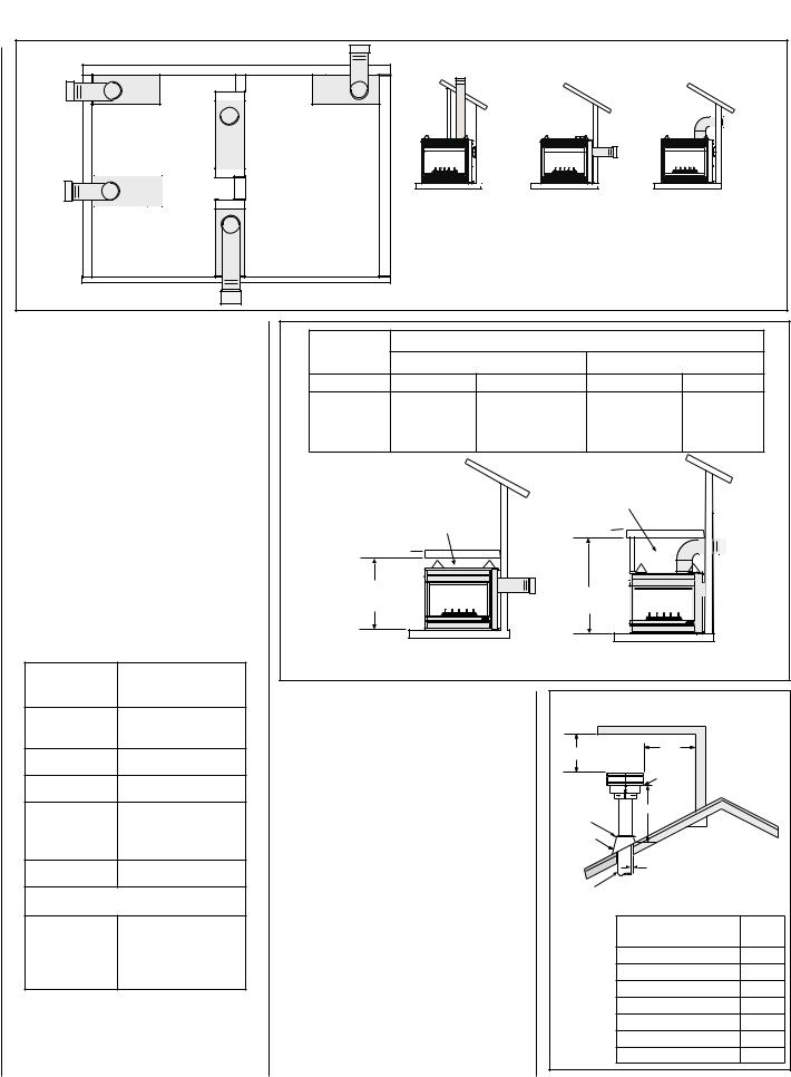
These direct vent appliances are uniquely suited for installations requiring a utility shelf positioned directly above the fireplace. Utility shelves like these are commonly used for locating television sets and decorative plants.
To achieve the lowest possible shelf height, use the alternative rear vent outlet. Do not insulate the space between the appliance and the area above it. See Figure 3 on page 4. The minimum height from the base of the appliance to the underside of combustible materials used to construct a utility shelf in this fashion is shown in the table in Figure 3 on page 4. The weight of the utility shelf and anything placed upon it may not
be supported by the appliance in anyway.
3
Corner - Right |
Corner - Left |
(CDCR) |
(CDCL) |
|
See-Through |
|
(CDST) |
Peninsula |
VERTICAL VENT |
HORIZONTAL VENT |
HORIZONTAL VENT |
|
- REAR |
- TOP |
|
(CDPF) |
See-Through |
|
|
|
one side flush |
|
|
|
with a wall (CDST) - |
|
|
Figure 2 |
|
|
TYPICAL LOCATIONS |
|
|
|
|
|
|
||
The appliance should be mounted on a fully |
|
|
Shelf Height inches (mm) |
|
|
||||||
supported base extending the full width and |
Model No. |
|
|
|
|||||||
Top Vent - with One 90 Degree Elbow |
Rear Vent - Straight Out the Back |
||||||||||
depth of the unit. The appliance may be located |
|
||||||||||
on or near conventional construction materi- |
|
Secure Vent |
Secure Flex |
|
Secure Vent |
Secure Flex |
|||||
als. However, if installed on combustible mate- |
CDST |
|
|
|
|
|
|
|
|
||
rials, such as carpeting, vinyl tile, etc., a metal |
CDPF |
53 1/2 (1359) |
55 1/4 (1403) |
|
41 1/8 (1045) |
41 1/8 (1045) |
|||||
or wood barrier covering the entire bottom |
CDCR |
|
|||||||||
|
|
|
|
|
|
|
|
||||
surface must be used. |
CDCL |
|
|
|
|
|
|
|
|
||
APPLIANCE AND VENT CLEARANCES |
|
|
|
|
Do not insulate the |
|
|
||||
|
|
|
|
space between the |
|
|
|||||
The appliance is approved with zero clearance to |
|
Do not insulate the |
|
|
appliance and the |
|
|
||||
combustible materials on all sides (as detailed in |
|
space between the |
|
|
|
area above it. |
|
|
|||
|
appliance and the |
|
|
|
|
|
|
|
|||
Table 2 ), with the following exception: When the |
|
area above it. |
|
|
|
|
|
|
|
||
unit is installed with one side flush with a wall, |
|
|
|
|
|
|
|
|
|
||
the wall on the other side of the unit must not |
|
|
|
|
|
|
|
|
|
||
extend beyond the front edge of the unit. In |
|
|
|
|
|
|
|
|
|
||
addition, when the unit is installed in the middle |
Shelf Height |
|
Shelf Height |
|
|
|
|||||
of a room, the side walls surrounding the unit |
(see table) |
|
|
|
|
||||||
|
|
(see table) |
|
|
|
||||||
must not extend beyond the front or rear edge |
|
|
|
|
|
|
|
|
|
||
of the unit. See Figure 2. |
|
Shelf Above Fireplace |
|
|
|
Shelf Above Fireplace |
|
||||
|
|
Figure 3 |
|
|
|
|
|||||
|
1/2 in. (13 mm) |
With Rear Venting |
|
|
|
|
With Top Venting |
|
|||
BACK |
|
|
|
|
|
|
|
|
|
||
0 in. (0 mm) spacers |
VENT TERMINATION CLEARANCES |
|
|
|
|
|
|
|
|||
|
|
|
|
TERMINATION HEIGHTS FOR VENTS ABOVE |
|
||||||
|
1/2 in. (13 mm) |
These instructions |
should be used as a |
|
|
|
FLAT OR SLOPED ROOFS |
|
|||
SIDES |
|
Horizontal Overhang |
|
|
|||||||
guideline and do not supersede local codes |
|
|
|
||||||||
0 in. (0 mm) spacers |
|
|
|
2 FT |
|
|
|||||
|
in any way. Install vent according to local |
|
|
|
Vertical |
|
|||||
|
|
|
|
|
|
||||||
TOP SPACERS |
0 in. (0 mm) |
2 FT MIN. |
MIN. |
Wall |
|
||||||
codes, these instructions, the current Na- |
|
|
|||||||||
|
|
|
Lowest |
|
|
||||||
|
|
tional Fuel Gas Code (ANSI-Z223.1) in the |
|
Vent |
Discharge |
|
|||||
FLOOR |
0 in. (0 mm) |
|
Opening |
|
|||||||
USA or the current standards of CAN/CGA- |
|
|
|||||||||
|
Termination |
|
|
|
|||||||
|
|
|
|
|
|
||||||
From Bottom |
|
B149.1 and -B149.2 in Canada. |
|
|
Storm Collar |
H* |
X |
|
|||
|
|
|
|
|
|
|
|||||
of Unit to |
64 in. (1626 mm) |
Vertical Vent Termination Clearances |
|
|
|
|
|
||||
|
Flashing |
|
12 |
|
|||||||
Ceiling |
|
Terminate single vent caps relative to |
|
|
|
|
Roof Pitch is X/12 |
||||
|
|
|
|
|
1 inch (25.4 mm) Minimum |
|
|||||
VENT |
1 in. (25.4 mm)* |
building components according |
to |
|
|
|
|
||||
|
|
|
Clearance to Combustibles |
|
|||||||
SERVICE CLEARANCES |
Figure 4. |
|
|
|
Concentric |
*H = MINIMUM HEIGHT FROM ROOF TO |
|||||
Terminate multiple vent terminations accord- |
|
Vent Pipe |
LOWEST DISCHARGE OPENING OF VENT |
||||||||
|
|
|
|
|
|
|
|
||||
VIEWING |
|
ing to the installation codes listed above. |
|
|
|
Roof Pitch |
H |
||||
|
|
|
|
|
|
|
(feet) |
||||
SIDES - |
3 Feet. (0.9 meters) |
Horizontal Vent Termination Clearances |
|
|
|
|
|
||||
|
|
|
Flat to 6/12 |
1.0 |
|||||||
(FRONT BACK |
|
|
|
||||||||
|
See Figure 5 on page 5 for horizontal vent |
|
|
|
Over 6/12 to 7/12 |
1.25 |
|||||
OR SIDE) |
|
|
|
|
|||||||
|
termination clearances to any overhead com- |
|
|
|
Over 7/12 to 8/12 |
1.5 |
|||||
|
|
|
|
|
|||||||
|
|
bustible projection less than or equal to 2 ¹⁄ " |
|
|
|
||||||
*Note: 3 in. (75 mm) above any horizontal/inclined |
|
|
|
Over 8/12 to 9/12 |
2.0 |
||||||
(64 mm) and greater than 2¹⁄ " (64 mm). For |
|
|
|
||||||||
vent component. |
|
|
|
|
Over 9/12 to 10/12 |
2.5 |
|||||
|
additional vent location restrictions refer to |
|
|
|
|||||||
|
|
|
|
|
Over10/12 to 11/12 |
3.25 |
|||||
Table 2 |
|
Figure 8 on page 6. |
|
|
Figure |
4 |
|||||
|
|
|
Over 11/12 to 12/12 |
4.0 |
|||||||
4 |
|
NOTE: DIAGRAMS & ILLUSTRATIONS NOT TO SCALE. |
|
|
|
|
|
|
|||

TYPICAL INSTALLATION SEQUENCE
The typical sequence of installation follows, however, each installation is unique resulting in variations to those described.
See the page numbers references in the following steps for detailed procedures.
Step 1. (page 5) Construct the appliance framing. Position the appliance within the framing and secure with nailing brackets.
Step 2. (page 10) Route gas supply line to appliance location.
Step 3. (page 10) Install the vent system and exterior termination.
Step 4. (page 22) Field Wiring
A.Millivolt Appliances – The operating control switch is factory installed.
B.Electronic Appliances – Connect 120 Vac electrical power to the appliance receptacle. Step 5. (page 22) Install blower kit (optional equipment).
Step 6. (page 23) Make connection to gas supply.
Step 7. (page 23) Install the log set, decorative volcanic stone and glowing embers. Step 8. (page 23) Checkout appliance operation.
Step 9. (page 24) Install glass enclosure panels.
Step 10. (page 24) Adjust burner primary air shutter to achieve proper flame appearance. Step 11. (page 25) Install the hoods.
Horizontal Vent Termination Clearances
Combustible Projection 2¹⁄ inches or less in length
Combustible Projection greater than 2¹⁄ inches in length
Unventilated
Ventilated Soffit
Soffit
|
|
3" |
18" |
12" |
(76 mm) |
(457 mm) |
(305 mm) |
|
Termination 
Kit
Note - See Figure 39 on page 17 for the exterior wall recess allowances of the square horizontal termination.
Figure 5 - Side Elevation View
DETAILED INSTALLATION STEPS
The appliance is shipped with all gas controls and components installed and pre-wired.
1 - Remove the shipping carton.
2 - Remove the top louver panel (see Figure 6).
3 - Lift the pressure relief plates and remove the cardboard from underneath each of them.
4 - Open the control compartment access panel by actuating the spring loaded magnetic catches securing the panel, gently depressing the outer top corners of the panel until the catches "pop" the panel free, allowing it to swing out and down to open.
5 - Open the two latches (located under the firebox floor) securing the glass enclosure panel. Remove the panel by tilting it outward at the bottom and lifting it up. Set the door aside protecting it from inadvertent damage. See
Figure 57 on page 24.
Top Louver Panel
Control Compartment Access Panel
Unit Parts Identification
Figure 6
Step 1. FRAMING
Frame these appliances as illustrated in
Figures 9 (CDST), 10 (CDPF), 11 (CDCL) or 12 (CDCR).
All framing details must allow for a minimum clearance to combustible framing members as shown inTable 2 on page 4.
Note: The CDST fireplace is installed in the framing by cocking it at an angle, fitting the collar side in first and then twisting and pushing the other side in. To minimize the obstruction, it is helpful to make sure the cap is removed from the rear collar.
If the appliance is to be elevated above floor level, a solid continuous platform must be constructed. Headers may be in direct contact with the appliance top spacers but must not be supported by them or notched to fit around them. All construction above the appliance must be self supporting, DO NOT use the appliance for structural support.
Side Nailing Flanges
The fireplace should be secured to the framing at the side(s) and/or rear of the unit using the factory-provided nailing flanges. Install the nailing flanges - 8 (CDST), 4 (CDPF, CDCL and CDCR) - as shown in Figure 7 using the existing screws. Position the fireplace within the framing. When required, the flanges may be bent 90 degrees by hand or with the assistance of a hammer. Use wood screws to secure the nailing flanges to the framing. See Table 2 on page 4 for clearances of framing members to cabinet parts in the nailing flange area. The nailing flange itself is exempt from these clearances.
Floor Nailing Tabs
Secure the fireplace to the floor as shown in
Figure 7.
CDST SHOWN |
CDCL SHOWN |
(CDPF - NO NAILING FLANGES |
|
ON END WITH GLASS PANEL) |
(FOR CDCR VIEW, INTERCHANGE SIDES) |
|
Remove these two screws and |
|
use them when installing |
|
the nailing flanges. |
Nailing Flanges |
|
Turn tabs down and secure to the floor with |
|
8d nails or other appropriate fasteners |
|
on all sides of the unit which do not have |
Figure 7 |
viewing glass panels. |
|
NOTE: DIAGRAMS & ILLUSTRATIONS NOT TO SCALE. |
5 |
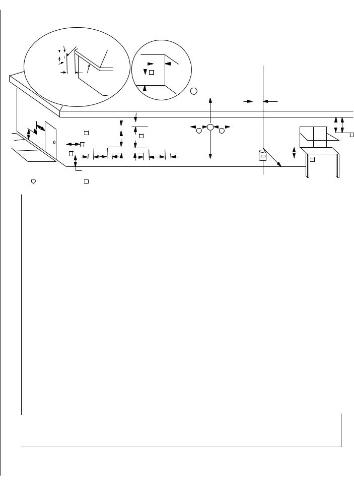
EXTERIOR HORIZONTAL VENT TERMINATION CLEARANCE REQUIREMENTS
* See Item D in the Text Below.
Exterior Wall |
|
Center Line |
|
|
|
|
|
|
|
|
|
|
|
|
|
|
Inside |
|
|
|
|
|
|
|
|
|
|
|
|
|
|
|
|
|
|
|
|
|
|
|
|
|
|
|
||||||||||||||||||||
|
|
|
|
|
|
|
|
|
of Termination |
|
|
|
|
|
|
|
|
|
|
|
|
|
|
|
|
|
|
|
|
|
|
|
|
|
|
|
|
|
|
|
|
|
|
|
|
|
|
|
|
|
||||||||||||||
|
|
|
|
|
|
|
|
|
|
|
|
|
|
|
|
|
|
|
|
|
|
|
|
|
|
|
Corner Detail |
|
|
|
|
|
|
|
|
|
|
|
|
|
|
|
|
|
|
|
|
|
|
|
|
|
|
|
||||||||||
|
|
|
|
|
|
|
|
|
|
|
|
|
|
|
|
|
|
|
|
|
|
|
|
|
|
|
|
|
|
|
|
|
|
|
|
|
|
|
|
|
|
|
|
|
|
|
|
|
|
|
|
|
|
|||||||||||
|
|
*18” |
|
|
|
|
|
|
|
|
|
|
|
|
|
|
|
|
|
|
|
|
|
|
|
|
|
|
|
|
|
|
|
|
|
|
|
|
|
|
|
|
|
|
|
|
|
|
|
|
|
|
|
|
|
|
|
|
|
|
||||
Horizontal |
|
|
|
|
|
|
|
|
|
|
|
|
|
|
|
|
|
|
|
|
|
|
|
|
|
G |
|
|
|
|
|
|
|
|
|
|
|
|
|
|
|
|
|
|
|
|
|
|
|
|
|
|
|
|
|
|
|
|
||||||
|
|
|
|
|
|
|
|
|
|
|
|
|
|
|
|
|
|
|
|
|
|
|
|
|
|
|
|
|
|
|
|
|
|
|
|
|
|
|
|
|
|
|
|
|
|
|
|
|
|
|
|
|||||||||||||
|
|
|
|
|
|
|
|
|
|
|
|
|
|
|
|
|
|
|
|
|
|
|
|
|
|
|
|
|
|
|
|
|
|
|
|
|
|
|
|
|
|
|
|
|
|
|
|
|
|
|
|
|
|
|||||||||||
Termination |
|
|
|
|
|
|
|
|
|
|
|
|
|
|
|
|
|
|
|
|
|
|
|
|
|
|
|
|
|
|
|
|
|
|
|
|
|
|
|
|
|
|
|
|
|
|
|
|
|
|
|
|
|
|
|
|
||||||||
|
|
|
|
|
|
|
|
|
|
|
|
|
|
|
|
|
|
|
|
|
|
|
|
|
|
|
|
|
|
|
|
|
|
|
|
|
|
|
|
|
|
|
|
|
|
|
|
|
|
|
|
|
|
|
|
|||||||||
|
|
|
|
|
18” |
|
|
|
|
|
|
|
|
|
|
|
|
|
|
|
|
|
|
|
|
|
|
|
|
|
|
|
|
|
|
|
|
|
|
|
|
|
|
|
|
|
|
|
|
|
|
|
|
|
|
|
|
|
||||||
|
|
|
|
|
|
|
Ventilated Soffit |
|
|
|
|
|
|
|
|
|
|
|
|
|
|
V |
|
|
|
|
|
|
|
|
|
|
|
|
|
|
|
|
|
|
|
|
|
|
|
|
|
|
|
|||||||||||||||
|
|
|
|
|
|
|
|
|
|
|
|
|
|
|
|
|
|
|
|
|
|
A |
|
|
|
|
|
|
|
|
|
|
|
|
|
|
|
|
|
|
|
|
|
|
|
|
|
|
|
|
|
|
|
|
|
|
|
|||||||
|
|
|
|
|
|
|
|
|
|
|
|
|
|
|
|
|
|
|
|
|
|
|
|
|
|
|
|
|
|
|
|
|
|
|
|
|
|
|
|
|
|
|
|
|
|
|
|
|
|
|
|
|
|
|
|
|
||||||||
|
|
Inside Corner |
|
|
|
|
|
|
|
|
|
|
|
|
|
|
|
|
|
|
|
|
|
= 9” in U.S. |
|
|
|
|
|
|
|
|
|
|
|
|
|
|
|
|
|
|
|
|||||||||||||||||||||
|
|
|
|
|
|
|
|
|
|
|
|
|
|
|
|
|
|
|
|
|
|
|
|
|
|
|
|
|
|
|
|
|
|
|
|
|
|
|
|
|
|
|||||||||||||||||||||||
|
|
|
|
|
|
|
|
|
|
|
|
|
|
|
|
|
|
|
|
|
|
|
|
|
|
|
|
|
|
|
|
|
|
|
|
|
|
|
|
|
|
|
|
|
||||||||||||||||||||
|
|
|
|
|
|
|
|
|
|
|
|
|
|
|
|
|
|
|
|
|
|
|
|
|
|
|
|
|
|
|
|
|
|
|
A |
|
|
|
|
|
|
|
|
|
|
|
|
|
|
|
|
|
|
|
||||||||||
|
|
|
|
|
|
|
|
|
|
|
|
|
|
|
|
|
|
|
|
|
|
|
|
|
|
|
|
|
|
|
|
|
|
|
|
|
|
|
|
|
|
|
|
|
|
|
|
|
|
|
|
|
|
|||||||||||
|
|
|
|
|
Detail D |
|
|
|
|
|
|
|
|
|
|
|
|
|
|
|
|
|
|
|
|
|
= 12” in Canada |
|
|
|
|
|
|
|
|
|
|
|
|
|
|
|
|
|
|
|
||||||||||||||||||
|
|
|
|
|
|
|
|
|
|
|
|
|
|
|
|
|
|
|
|
|
|
|
|
|
|
|
|
|
|
|
|
|
|
|
|
|
|
|
|
|
|
|
|
|
|
|
|
|||||||||||||||||
|
|
|
|
|
|
|
|
|
|
|
|
|
|
|
|
|
|
|
|
|
|
|
|
|
|
|
|
|
|
|
|
|
|
|
|
|
|
|
|
|
|
|
|
|
|
|
|
|
|
|
|
|
|
|
|
|||||||||
|
|
|
|
|
|
|
|
|
|
|
|
|
|
|
|
|
|
|
|
|
|
|
|
|
|
|
|
|
|
|
|
|
|
|
|
|
|
|
|
3 ft. |
|
|
|
|
|
|
H |
|
|
|||||||||||||||
|
|
|
|
|
|
|
|
|
|
|
|
|
|
|
|
|
|
|
|
|
|
|
|
|
|
|
|
|
|
|
|
|
|
|
|
|
|
|
|
|
|
|
|
|
|
|
|
|
|
|
|
|
|
|
|
|
|
|
|
|
|
|
||
B |
|
|
|
|
|
|
|
|
|
|
|
|
|
|
|
|
|
|
|
|
|
|
|
|
|
|
|
|
|
|
|
|
|
|
|
|
|
|
|
|
|
|
|
|
|
|
|
|
|
|
|
|
|
|
|
|
|
|
E |
|||||
|
|
|
|
|
|
|
|
|
|
|
|
|
|
|
|
|
|
|
|
|
|
|
|
|
|
|
|
|
|
|
|
|
|
|
|
|
|
|
|
|
|
|
|
|
|
|
|
|
|
|
|
|
|
|||||||||||
|
|
|
|
|
|
|
|
|
|
|
|
|
|
|
|
|
|
|
B |
|
|
|
|
|
|
|
|
|
|
X |
|
|
|
|
|
|
|
|
|
|
|
|
|
|
|
|
|
D |
|
|
|
|||||||||||||
V |
|
|
|
|
|
|
|
|
|
|
|
|
|
C |
|
|
|
|
|
|
|
|
|
|
|
|
|
|
|
A |
|
|
A |
|
|
|
|
|
|
|
|
|
|
|
|
|
|
|
|
|
|
|
|
|||||||||||
|
|
|
|
|
|
|
V |
|
|
|
|
|
|
|
|
|
|
|
|
|
|
|
|
|
|
|
|
|
|
|
|
|
|
|
|
|
|
|
|
|
|
|
|
|
|
|
|
|
|
|
|
|
|
|
|
|
||||||||
L |
|
|
|
|
|
|
|
|
|
|
|
|
|
|
|
|
|
|
|
|
|
|
|
|
|
|
|
|
|
|
|
|
|
|
|
|
|
|
|
|
|
|
|
|
|
|
|
|
|
|
|
|
|
|
|
|
|
|
V |
|||||
|
|
|
|
|
|
|
|
Fixed |
|
|
|
|
|
|
|
|
|
|
V |
|
|
|
Operable |
|
|
|
|
|
|
|
|
|
|
|
|
|
|
|
|
|
|
|
|
|
|
|
|
|
|
|
|
|
|
|
||||||||||
|
|
|
|
|
|
|
|
|
|
|
|
|
|
|
|
|
|
|
|
|
|
|
|
|
|
|
|
|
|
|
|
|
|
|
|
|
|
|
|
|
|
|
|
|
|
|
|
|
|
|
|
|
|
|||||||||||
|
|
|
|
|
|
|
|
|
|
|
|
|
|
Closed |
|
|
|
|
|
|
|
|
|
|
|
|
|
|
Window |
|
|
|
|
|
|
|
3 ft. |
|
|
|
|
|
|
|
|
|
|
|
|
|
|
|
|
|
|
|
|
|
|
|||||
|
|
|
|
|
|
|
|
|
|
|
|
|
|
Window |
|
|
|
|
|
|
|
|
|
|
|
|
|
|
|
|
|
|
|
|
|
|
|
|
|
|
|
|
|
|
|
|
|
|
|
|
|
|
|
|
|
|
|
|
|
|
||||
|
|
|
|
|
|
F |
|
|
V |
|
|
|
|
|
|
|
|
|
|
|
|
|
|
|
|
|
|
|
|
|
|
|
|
|
|
|
|
|
|
|
|
|
|
|
|
|
|
|
|
|
|
|
|
|
|
|
||||||||
|
|
|
|
|
|
|
|
|
|
|
|
|
|
|
|
|
|
|
|
|
|
|
|
|
|
|
|
|
|
|
|
|
|
|
|
|
|
|
|
|
|
|
|
|
|
|
|
|
|
|
|
|
|
|
|
|
|
|
|
|
||||
|
|
|
|
|
|
|
|
|
|
|
|
|
|
|
C |
|
|
|
|
|
|
|
|
|
|
|
|
|
|
J |
|
|
|
|
|
|
|
|
|
|
|
|
|
|
|
|
|
|
|
|
|
|
|
|
|
|
|
|||||||
|
|
|
|
|
|
|
|
|
|
|
|
|
|
|
|
|
|
|
|
|
|
|
|
|
|
|
|
|
|
|
|
|
|
|
|
|
|
|
|
|
|
|
|
|
|
|
|
|
|
|
|
|
|
|
|
|||||||||
|
|
|
|
|
|
V |
|
|
|
|
|
|
|
|
|
|
|
|
B |
|
|
|
|
|
|
|
|
|
|
|
|
|
|
|
|
|
|
|
M |
|
|
|
|
|
|
|
|
|
|
|
|
|
||||||||||||
|
|
|
|
|
|
|
|
|
|
|
|
|
|
|
|
|
|
|
|
|
|
|
|
|
|
|
|
|
|
|
|
|
|
|
|
|
|
|
|
|
|
|
|
|
|
|
|
|
|
|
|
|
|
|
|
|
|
|
|
|
||||
|
|
|
|
C |
|
|
C |
|
|
|
|
|
|
|
|
B |
|
|
|
B |
|
|
|
|
|
|
|
|
|
|
|
|
|
|||||||||||||||||||||||||||||||
|
|
|
|
|
|
|
|
|
|
|
|
|
|
|
|
|
|
|
|
|
|
|
|
|
|
|
|
|
|
|
|
|
|
|
|
|
|
|
|
|
|
|
|
|
|
|
|
|
|
|
|
|
|
|||||||||||
|
|
|
|
|
|
|
|
|
|
|
|
|
|
|
|
|
|
|
|
|
|
|
|
|
|
|
|
|
|
|
|
|
|
|
|
|
|
|
|
|
|
|
|
|
|
|
|
|
|
|
|
|
||||||||||||
|
|
|
|
|
|
|
|
|
|
|
|
|
|
|
|
|
|
|
|
|
|
|
|
|
|
|
|
|
|
|
|
I |
|
|
V |
|
|
|
|
|
|
|
|
|
||||||||||||||||||||
|
|
|
|
|
|
|
|
|
|
|
|
|
|
|
|
|
|
|
|
|
|
|
|
|
|
|
|
|
|
|
|
|
|
|
|
|
|
|
|
|
|
|
|
|
|
|||||||||||||||||||
|
|
|
|
|
|
|
|
|
|
|
A |
|
|
|
|
|
|
|
|
|
|
|
|
|
|
|
|
|
|
|
|
|
|
|
|
|
|
|
|
|
|
|
|
|
|
|
|
|
|
|
|
|
|
|
|
|
||||||||
|
|
|
|
|
|
|
|
|
|
|
|
|
|
|
|
|
|
|
|
|
|
|
|
|
|
|
|
|
|
|
|
|
|
|
|
|
|
|
|
|
|
|
|
|
|
|
|
|
|
|
|
|
|
|
|
|
||||||||
|
|
|
|
|
|
|
|
|
|
|
|
|
|
|
|
|
|
|
|
|
|
|
|
|
|
|
|
|
|
|
|
|
|
|
|
|
|
|
|
|
|
|
|
|
|
|
|
|
|
|
||||||||||||||
X = Air Supply Inlet |
|
|
|
|
= Vent Terminal |
|
|
= Area where Terminal is not Permitted |
|
|
|
|
|
|
|
|
|
|
|
|
|
|
|
|
|
|
|
|
|
|
||||||||||||||||||||||||||||||||||
|
|
|
V |
|
|
|
|
|
|
|
|
|
|
|
|
|
|
|
|
|
|
|
|
|
|
|
|
|||||||||||||||||||||||||||||||||||||
|
|
|
|
|
|
|
|
|
|
|
|
|
|
|
|
|
|
|
|
|
|
|
|
|
|
|
|
|||||||||||||||||||||||||||||||||||||
|
|
|
|
|
|
|
|
|
|
|
|
|
|
|
|
|
|
|
|
|
|
|
|
|
|
|
|
|
|
|
|
|
|
|
|
|
|
|
|
|
|
|
|
|
|
|
|
|
|
|
|
|
|
|
|
|
|
|
|
|
|
|
|
|
|
|
|
|
|
|
|
|
|
|
|
|
|
|
|
|
|
|
|
|
|
|
|
|
|
|
|
|
|
|
|
|
Canadian Installation* |
|
|
|
|
|
US Installation** |
|
|
||||||||||||||||||||||||
|
|
|
|
|
|
|
|
|
|
|
|
|
|
|
|
|
|
|
|
|
|
|
|
|
|
|
|
|
|
|
|
|
|
|
|
|
|
|
|
|
|
|
|
|
|
|
|
|
|
|
|
|
|
|
|
|
|
|
|
|
|
|
|
|
A = Clearance above grade, veranda, porch, |
|
|
12 inches (30cm)* |
|
|
|
|
|
|
|
|
12 inches (30cm)** |
|
|
||||||||||||||||||||||||||||||||||||||||||||||||||
deck, or balcony. |
|
|
|
|
|
|
|
|
|
|
|
|
|
|
|
|
|
|
|
|
|
|
|
|
|
|
|
|
|
|
|
|
|
|
|
|
|
|
|
|
|
|
|
|
|
|
|
|
|
|
|
|
|
|
|
|
||||||||
|
|
|
|
|
|
|
|
|
|
|
|
|
|
|
|
|
|
|
|
|
|
|
|
|
|
|
|
|
|
|
|
|
|
|
|
|
|
|
|
|
|
|
|
|
|
|
|
|
|
|
|
|
|
|
|
|
|
|
|
|
|
|
|
|
B = Clearance to window or door that may be |
|
|
6 in (15cm) for appliances |
|
|
|
|
|
|
|
|
6 in (15cm) for appliances |
|
|
||||||||||||||||||||||||||||||||||||||||||||||||||
opened. |
|
|
|
|
|
|
|
|
|
|
|
|
|
|
|
|
< 10,000 Btuh (3kW), 12 in (30cm) |
|
|
|
< 10,000 Btuh (3kW), 9 in (23cm) |
|
|
|||||||||||||||||||||||||||||||||||||||||
|
|
|
|
|
|
|
|
|
|
|
|
|
|
|
|
|
|
|
|
|
|
|
|
|
for appliances > 10,000 Btuh (3kW) and |
for appliances > 10,000 Btuh (3kW) and |
|
|
||||||||||||||||||||||||||||||||||||
|
|
|
|
|
|
|
|
|
|
|
|
|
|
|
|
|
|
|
|
|
|
|
|
|
< 100,000 Btuh (30kW), 36 inches (91cm) |
< 50,000 Btuh (15kW), 12 inches (30cm) |
|
|
||||||||||||||||||||||||||||||||||||
|
|
|
|
|
|
|
|
|
|
|
|
|
|
|
|
|
|
|
|
|
|
|
|
|
for appliances > 100,000 Btuh (30kW)* |
for appliances > 50,000 Btuh (15kW)** |
|
|
||||||||||||||||||||||||||||||||||||
C = Clearance to permanently closed window |
|
|
12" (305mm) minimum to prevent window |
9" (229mm) minimum to prevent window |
|
|
||||||||||||||||||||||||||||||||||||||||||||||||||||||||||
|
|
|
|
|
|
|
|
|
|
|
|
|
|
|
|
|
|
|
|
|
|
|
|
|
condensation |
|
|
|
|
|
|
|
|
condensation |
|
|
||||||||||||||||||||||||||||
|
|
|
|
|
|
|
|
|
|
|
|
|
|
|
|
|
|
|
|
|
|
|
|
|
|
|
|
|
|
|
|
|
|
|
|
|
|
|
|
|
|
|
|
|
|
|
|
|
|
|
|
|
|
|
|
|
|
|
|
|
|
|
|
|
D = Vertical clearance to ventilated soffit |
|
|
18" (458mm) |
|
|
|
|
|
|
|
|
18" (458mm) |
|
|
||||||||||||||||||||||||||||||||||||||||||||||||||
located above the terminal within a horizontal |
|
|
|
|
|
|
|
|
|
|
|
|
|
|
|
|
|
|
|
|
|
|
|
|
|
|
|
|
|
|
|
|
|
|
|
|
|
|
|
|
|
|
||||||||||||||||||||||
distance of 18 inches (458mm) from the center |
|
|
|
|
|
|
|
|
|
|
|
|
|
|
|
|
|
|
|
|
|
|
|
|
|
|
|
|
|
|
|
|
|
|
|
|
|
|
|
|
|
|
||||||||||||||||||||||
line of the terminal |
|
|
|
|
|
|
|
|
|
|
|
|
|
|
|
|
|
|
|
|
|
|
|
|
|
|
|
|
|
|
|
|
|
|
|
|
|
|
|
|
|
|
|
|
|
|
|
|
|
|
|
|
|
|
|
|
||||||||
E = Clearance to unventilated soffit |
|
|
|
|
|
|
|
|
|
12" (305mm) |
|
|
|
|
|
|
|
|
12" (305mm) |
|
|
|||||||||||||||||||||||||||||||||||||||||||
F = Clearance to outside corner |
|
|
|
|
|
|
|
|
|
|
|
5" (12.7cm) minimum |
|
|
|
|
|
|
|
|
5" (12.7cm) minimum |
|
|
|||||||||||||||||||||||||||||||||||||||||
G = Clearance to inside corner |
|
|
|
|
|
|
|
|
|
|
|
6" (15.2cm) minimum |
|
|
|
|
|
|
|
|
6" (15.2cm) minimum |
|
|
|||||||||||||||||||||||||||||||||||||||||
|
|
|
|
|
|
|
|
|
|
|
|
|
|
|
|
|
|
|
|
|
|
|
|
|
|
|
|
|
|
|
|
|
|
|
|
|
|
|
|
|
|
|
|
|
|
|
|
|
|
|
|
|
|
|
|
|
|
|
|
|
|
|
||
H = Clearance to each inside of center line |
|
|
3 feet (91cm) within a height of 15 feet |
3 feet (91cm) within a height of 15 feet |
|
|
||||||||||||||||||||||||||||||||||||||||||||||||||||||||||
extended above meter/regulator assembly |
|
|
above the meter/regulator assembly* |
|
|
|
above the meter/regulator assembly** |
|
|
|||||||||||||||||||||||||||||||||||||||||||||||||||||||
I = Clearance to service regulator vent outlet |
|
|
3 feet (91cm)* |
|
|
|
|
|
|
|
|
3 feet (91cm)** |
|
|
||||||||||||||||||||||||||||||||||||||||||||||||||
|
|
|
|
|
|
|
|
|
|
|
|
|
|
|
|
|
|
|
|
|
|
|
|
|
|
|
|
|
|
|
|
|
|
|
|
|
|
|
|
|
|
|
|
|
|
|
|
|
|
|
|
|
|
|
|
|
|
|
|
|
|
|
|
|
J = Clearance to nonmechanical air supply inlet |
|
|
6 in (15cm) for appliances |
|
|
|
|
|
|
|
|
6 in (15cm) for appliances |
|
|
||||||||||||||||||||||||||||||||||||||||||||||||||
to building or the combustion air inlet to any |
|
|
< 10,000 Btuh (3kW), 12 in (30cm) |
|
|
|
< 10,000 Btuh (3kW), 9 in (23cm) |
|
|
|||||||||||||||||||||||||||||||||||||||||||||||||||||||
other appliance |
|
|
|
|
|
|
|
|
|
|
|
|
|
|
|
|
for appliances > 10,000 Btuh (3kW) and |
for appliances > 10,000 Btuh (3kW) and |
|
|
||||||||||||||||||||||||||||||||||||||||||||
|
|
|
|
|
|
|
|
|
|
|
|
|
|
|
|
|
|
|
|
|
|
|
|
|
< 100,000 Btuh (30kW), 36 inches (91cm) |
< 50,000 Btuh (15kW), 12 inches (30cm) |
|
|
||||||||||||||||||||||||||||||||||||
|
|
|
|
|
|
|
|
|
|
|
|
|
|
|
|
|
|
|
|
|
|
|
|
|
for appliances > 100,000 Btuh (30kW)* |
for appliances > 50,000 Btuh (15kW)** |
|
|
||||||||||||||||||||||||||||||||||||
K = Clearance to a mechanical air supply inlet |
|
|
6 feet (1.83m)* |
|
|
|
|
|
|
|
|
3 feet (91cm) above if within 10 feet (3m) |
|
|
||||||||||||||||||||||||||||||||||||||||||||||||||
|
|
|
|
|
|
|
|
|
|
|
|
|
|
|
|
|
|
|
|
|
|
|
|
|
|
|
|
|
|
|
|
|
|
|
|
|
|
|
|
|
|
|
|
|
|
horizontally** |
|
|
||||||||||||||||
L = Clearance above paved sidewalk or paved |
|
|
7 feet (2.13m)‡ |
|
|
|
|
|
|
|
|
7 feet (2.13m)‡ |
|
|
||||||||||||||||||||||||||||||||||||||||||||||||||
diveway located on public property |
|
|
|
|
|
|
|
|
|
|
|
|
|
|
|
|
|
|
|
|
|
|
|
|
|
|
|
|
|
|
|
|
|
|
|
|
|
|
|
|
|
|
|
|
|
|
|
|
|
|||||||||||||||
M = Clearance under veranda, porch, deck or |
|
|
12 inches (30cm)*‡ |
|
|
|
|
|
|
|
|
12 inches (30cm)‡ |
|
|
||||||||||||||||||||||||||||||||||||||||||||||||||
balcony |
|
|
|
|
|
|
|
|
|
|
|
|
|
|
|
|
|
|
|
|
|
|
|
|
|
|
|
|
|
|
|
|
|
|
|
|
|
|
|
|
|
|
|
|
|
|
|
|
|
|
|
|
|
|
|
|
||||||||
* In accordance with the current CSA-B149.1 National Gas And Propane Installation Code. ** In accordance with the curent ANSI SZ223.1/NFPA 54 National Fuel Gas Codes.
‡ A vent shall not terminate directly above a sidewalk or paved driveway which is located between two single family dwellings and serves both dwellings.
*‡ Only permitted if veranda, porch, deck or balcony is fully open on a minimum 2 sides beneath the floor:
Figure 8
6 |
NOTE: DIAGRAMS & ILLUSTRATIONS NOT TO SCALE. |

FIREPLACE FRAMING SPECIFICATIONS
CDST |
|
11³⁄ |
inches (millimeters) |
|
CDPF (Peninsula) |
11³⁄ |
inches (millimeters) |
|||||||
|
Minimum Framing |
|
|
|
|
|
|
|||||||
(See-Through) |
|
|
|
|
|
|
|
Minimum Framing |
||||||
|
|
10¹⁄ |
Stud Size is 2x4 |
|
|
|
|
10¹⁄ |
|
Stud Size is 2x4 |
|
|||
|
|
(267) |
|
VENT FRAMING - |
|
|
|
|
(267) |
|
|
VENT FRAMING - |
||
|
|
|
|
|
|
|
|
|
|
|||||
|
|
|
|
TOP VENT WITH |
|
|
|
|
|
|
|
TOP VENT WITH |
||
|
|
|
|
ONE 90º ELBOW |
|
|
|
|
|
|
|
ONE 90º ELBOW |
||
|
|
|
|
VENT FRAMING - |
|
|
|
|
|
|
|
VENT FRAMING - |
||
|
7 |
|
|
REAR VENT WITH |
|
|
7 |
|
|
|
|
REAR VENT WITH |
||
(178) |
|
|
NO ELBOWS |
|
(178) |
|
|
|
NO ELBOWS |
|
||||
12¹⁄ |
|
|
|
|
|
12¹⁄ |
|
|
|
|
|
|
|
|
(308) |
|
|
|
|
|
(308) |
|
|
|
|
|
|
|
|
|
7 |
|
|
|
|
|
|
7 |
|
|
|
|
|
|
5¹⁄ |
(178) |
|
|
|
|
5¹⁄ |
(178) |
|
|
|
|
|
|
|
|
|
|
|
|
|
|
|
|
|
|
|
|
||
(130) |
|
|
|
|
|
(130) |
|
|
|
|
|
|
|
|
12¹⁄ |
|
|
|
|
|
12¹⁄ |
|
|
|
|
|
|
|
|
(308) |
|
|
|
|
|
(308) |
|
|
|
|
|
|
|
|
5¹⁄ |
|
³⁄ |
A |
|
|
5¹⁄ |
|
|
26³⁄ |
A |
|
|
|
|
|
|
26 |
|
|
|
(130) |
|
|
|
|
|
|
||
(130) |
(679) |
|
|
|
|
(679) |
|
|
|
|
|
|||
Gas Line |
|
|
|
6¹⁄ |
*41¹⁄ |
Gas Line |
|
|
|
|
|
6¹⁄ |
|
*41¹⁄ |
Center of gas line |
|
|
Center of gas line |
|
|
|
|
|
||||||
|
|
(159) |
(1054) |
|
|
|
|
(159) |
|
|||||
is 3 in. (76 mm) |
|
|
|
is 3 in. (76 mm) |
|
|
|
|
|
|
(1054) |
|||
up from floor. |
|
|
|
|
|
up from floor. |
|
|
|
|
|
|
|
|
Dimension A |
48¹⁄ |
|
22³⁄ |
|
Dimension A |
43 ⁄ |
|
|
|
22³⁄ |
||||
|
(578) |
|
|
|
|
(578) |
||||||||
Secure Vent - 46 (1168) |
|
|
|
|
|
|||||||||
(1108) |
|
|
|
Secure Vent - 46 (1168) |
(1108) |
|
|
|
|
|
||||
Secure Flex - 47 ³⁄ (1213) |
|
|
|
|
|
|
|
|
||||||
|
|
|
|
Secure Flex - 47 ³⁄ (1213) |
|
|
|
|
|
|
||||
|
|
|
|
|
|
|
|
|
|
|
|
|||
|
*This dimension can be reduced to 41 inches (1041 mm). This |
|
|
*This dimension can be reduced to 41 inches (1041 mm). This results |
||||||||||
|
results in 0 in. (0 mm) clearance between framing and unit framing |
|
|
|||||||||||
|
|
|
in 0 in. (0 mm) clearance between framing and unit framing spacers. |
|||||||||||
|
spacers. (The 41¹⁄ |
in. dimension permits easier fireplace |
|
|
||||||||||
Figure 9 |
Figure 10 |
|
(The 41¹⁄ in. dimension permits easier fireplace installation, if unit |
|||||||||||
installation, if unit |
is installed after framing is erected.) |
|
||||||||||||
|
is installed after framing is erected.) |
|
|
|||||||||||
CDCL (Corner-Left) |
10³⁄ |
|
Dimension A |
|
CDCR (Corner-Right) |
|
10³⁄ |
|
|
Dimension A |
||||
|
Secure Vent - 46 (1168) |
|
|
|
|
(264) |
|
Secure Vent - 46 (1168) |
||||||
|
|
(264) |
|
inches (millimeters) |
|
|
||||||||
inches (millimeters) |
|
Secure Flex - 47 ³⁄ (1213) |
|
|
|
Secure Flex - 47 ³⁄ (1213) |
||||||||
|
12¹⁄ |
Minimum Framing |
|
|
|
|||||||||
|
|
|
|
10¹⁄ |
|
|
||||||||
Minimum Framing |
10¹⁄ |
|
|
|
|
|
||||||||
(318) |
VENT FRAMING - |
|
Stud Size is 2x4 |
|
|
|
(267) |
|
|
|||||
Stud Size is 2x4 |
|
(267) |
|
|
|
|
VENT FRAMING - |
|||||||
|
|
REAR VENT WITH |
|
VENT FRAMING - |
|
12¹⁄ |
|
|
|
|||||
|
|
|
|
|
|
|
|
|
||||||
|
|
|
|
NO ELBOWS |
|
|
|
|
5¹⁄ |
TOP VENT WITH |
||||
|
5¹⁄ (133) |
|
|
|
REAR VENT WITH |
|
(318) |
|
|
|||||
|
|
|
|
|
|
|
|
(133) |
ONE 90º ELBOW |
|||||
|
|
|
|
|
|
|
|
|
||||||
VENT FRAMING - |
|
|
|
|
NO ELBOWS |
|
|
|
|
|
|
|
|
|
|
|
10¹⁄ |
|
|
|
10¹⁄ |
|
|
|
|
|
|||
TOP VENT WITH |
|
|
|
|
|
|
|
|
|
|
||||
ONE 90º ELBOW |
|
|
(267) |
|
|
|
(267) |
|
|
|
|
|
||
|
|
|
|
5¹⁄ |
|
|
|
5¹⁄ |
|
|
|
|
|
|
|
|
|
(133) |
|
|
|
|
|
|
|
|
|
||
|
|
|
|
|
|
(133) |
|
|
|
7 |
|
|
||
|
|
|
|
|
|
|
|
|
|
|
|
|
||
|
7 |
|
|
|
|
|
|
|
|
|
|
(178) |
|
|
(178) |
|
|
|
|
|
|
|
|
|
|
|
|
|
|
12¹⁄ |
5¹⁄ |
|
|
|
|
|
|
|
|
|
|
|
5¹⁄ |
12¹⁄ |
(308) |
(130) |
|
|
7 |
|
7 |
|
|
|
|
|
(130) |
(308) |
|
|
|
|
|
|
(178) |
|
|
|
|
|
|
|
|
|
|
|
|
|
(178) |
|
|
|
|
|
|
|
|
|
|
|
|
|
|
|
|
|
|
|
|
|
|
|
|
|
|
|
|
|
|
12¹⁄ |
12¹⁄ |
|
|
|
|
|
|
|
|
|
|
|
|
5¹⁄ |
(308) |
(308) 5¹⁄ |
|
|
|
|
|
|
|
|
|
|
|
|
(130) |
(130) |
|
|
|
|
|
|
|
|
|
|
|
|
26³⁄ |
|
|
|
|
26³⁄ |
|
|
|
|
|
|
|
|
|
|
|
|
(679) |
A |
|
|
|
||||
|
|
A |
(679) |
|
|
|
*41¹⁄ |
|
||||||
|
|
|
Gas Line |
|
|
|
|
|
|
|
||||
|
|
|
|
|
|
|
|
|
|
(1054) |
|
|||
|
*41¹⁄ |
|
|
Center of gas line |
|
|
|
|
|
|
|
|
|
|
|
|
|
is 3 in. (76 mm) |
|
|
|
|
|
|
|
|
|
||
|
(1054) |
|
|
|
|
|
|
|
|
|
|
|
||
|
|
|
up from floor. |
|
|
|
|
|
|
|
|
|
||
|
|
|
|
|
|
|
|
|
|
|
|
|
||
|
|
9³⁄ |
|
6¹⁄ |
|
|
|
|
|
|
|
|
|
|
(248)(159)
|
43 ⁄ |
|
|
43 ⁄ |
|
|
|
(1108) |
|
|
(1108) |
9 ⁄ |
|
|
Optional Gas Line Location |
|
|
|
(251) |
|
|
|
Gas Line Center of |
|
|
||
24 |
Center of gas line is |
|
24 |
|
||
(610) |
3 in. (76 mm) up from floor. |
|
gas line is 3 in. (76 mm) |
(610) |
|
|
|
|
|
up from floor. |
|
|
|
|
*This dimension can be reduced to 41 inches (1041 mm). This results |
|
|
*This dimension can be reduced to 41 inches (1041 mm). This results |
||
|
in 0 in. (0 mm) clearance between framing and unit framing spacers. |
|
|
in 0 in. (0 mm) clearance between framing and unit framing spacers. |
||
Figure 11 |
(The 41¹⁄ in. dimension permits easier fireplace installation, if unit |
|
Figure 12 |
(The 41¹⁄ in. dimension permits easier fireplace installation, if unit is |
||
is installed after framing is erected.) |
|
installed after framing is erected.) |
|
|
||
|
|
|
|
|
|
|
|
NOTE: DIAGRAMS & ILLUSTRATIONS NOT TO SCALE. |
7 |
||||

FIREPLACE SPECIFICATIONS |
|
|
|
|
|
|
|
|
|
|
|
|
|
CDST (See-Through) |
FINISH WALL BRACKET |
10 |
|
|
|
|
|
|
|
|
|||
(Front and back edge of unit top) |
(254) |
|
|
|
|
|
|
|
|
|
|
||
|
|
|
|
|
|
|
|
|
|
|
|
|
|
12 (305) |
|
|
|
1/2 |
FRAMING SPACERS |
|
|
|
|
|
|
|
|
(13) |
|
|
|
|
NOTE - Unit has a factory-installed |
|||
|
(Top and Both Sides) |
|
|
|
|
||||
|
|
|
|
|
|
vent sea cap and vent cover plate |
|||
|
|
|
|
|
|
|
|
||
|
|
|
|
|
FLUE |
|
|
(see Figures 17 and 18 on page 10) |
|
|
|
|
|
|
(Top or Side) |
|
|
in each flue outlet. The vent seal |
|
|
|
|
|
|
|
⁄ |
cap is not shown in this figure. |
||
|
|
|
|
|
|
|
|||
|
|
|
|
|
|
|
|
|
|
|
DETAIL OF |
|
|
|
40¹⁄ |
|
(16) |
|
|
|
|
3¹⁄ |
(89) |
|
|
|
|
||
|
FINISH WALL |
|
|
|
|
|
|||
|
|
(1019) |
|
Stepped to Accept Drywall on All 4 Corners |
|||||
|
BRACKET |
|
|
|
3¹⁄ (89) |
||||
|
|
|
|
|
|||||
|
|
|
|
|
TOP VIEW |
|
|
2¹⁄ |
|
|
|
|
|
¹⁄ (13) |
|
¹⁄ (13) |
|
|
|
|
24 |
|
|
47¹⁄ |
|
(63.5) |
12 |
||
|
|
|
|
|
|
||||
|
(610) |
|
|
|
(1197) |
|
|
|
(305) |
|
|
|
4 (102) |
|
|
|
|
|
|
|
|
|
|
|
|
|
|
|
10¹⁄ |
|
|
|
|
|
|
|
|
|
(260) |
|
|
|
41 |
|
|
|
2¹⁄ |
|
|
|
GAS INLET |
(1041) |
|
|
|
|
|
||
|
|
|
|
(63.5) |
FLUE |
ELECTRICAL |
|||
|
ELECTRICAL |
|
|
37 |
|
|
|||
|
|
|
|
|
|
||||
|
|
|
(940) |
|
|
|
(Top or Side) |
INLETS |
|
|
INLETS |
|
|
|
|
|
|
||
|
|
|
|
|
|
|
|
||
|
|
3 |
|
|
|
|
|
|
|
|
|
|
|
|
|
|
|
GAS INLET |
|
|
|
|
(76) |
|
|
|
|
|
|
|
|
|
|
|
|
|
|
|
|
|
|
|
|
|
|
|
|
|
ELECTRICAL |
|
|
|
|
|
|
|
3 (76) |
|
INLETS |
|
|
|
|
|
|
|
|
|
|
|
10¹⁄ |
|
|
|
|
CONTROL |
|
6 ⁄ |
|
|
(267) |
|
|
|
|
COMPARTMENT |
|
(175) |
|
Figure 13 |
LEFT SIDE VIEW |
|
|
|
FRONT VIEW |
ACCESS PANEL |
|
RIGHT SIDE VIEW |
|
|
|
|
|
|
|||||
CDPF (Peninsula) |
FINISH WALL BRACKET |
10 |
Stepped to Accept Drywall on Two Corners |
||||
(Front, back, and left edge of unit top) |
(254) |
|
FRAMING SPACERS |
||||
|
|
|
|
|
|
(Top and Side) |
|
|
|
|
FLUE |
|
12 (305) |
|
|
|
NOTE - Unit has a factory-installed |
(Top or Side) |
|
|
|
|
|
|
|
|
|
|
|
||
|
vent seal cap and vent cover plate |
|
|
|
|
DETAIL OF |
|
|
(see Figures 17 and 18 on page 10) |
|
|
|
|
||
|
|
|
|
FINISH WALL BRACKET |
|||
|
in each flue outlet. The vent seal |
|
|
|
|||
|
|
|
|
|
|
||
|
cap is not shown in this figure. |
|
|
|
|
¹⁄ |
|
|
|
|
|
|
⁄ |
|
(13) |
|
|
|
40¹⁄ |
|
(16) |
|
|
|
|
|
|
|
|
|
|
|
|
|
(1019) |
|
3¹⁄ (89) |
|
|
|
|
|
TOP VIEW |
|
|
|
|
|
|
|
|
|
|
|
|
|
24 |
|
43 ⁄ |
|
|
2¹⁄ |
12 |
|
|
|
|
(63.5) |
|||
|
|
|
|
(305) |
|||
|
(610) |
|
(1108) |
|
(13) |
||
|
|
¹⁄ |
|
||||
|
|
|
|
|
4 (102) |
|
|
|
|
|
|
|
|
|
10¹⁄ |
|
|
|
|
|
37 |
|
(260) |
|
|
|
|
|
|
|
|
|
|
|
|
|
(940) |
|
|
|
|
|
41 |
2¹⁄ |
|
|
|
|
|
|
(1041) |
|
FLUE |
||
|
|
|
|
(63.5) |
|
||
|
|
|
|
|
(Top or Side) |
||
|
|
|
|
|
|
|
|
|
|
|
|
|
|
|
ELECTRICAL |
|
|
|
|
|
|
|
INLETS |
|
|
|
|
|
|
|
GAS INLET |
|
|
|
|
|
|
3 (76) |
|
Figure 14 |
|
|
|
CONTROL COMPARTMENT |
6 ⁄ |
|
|
LEFT SIDE VIEW |
|
FRONT VIEW |
ACCESS PANEL |
RIGHT SIDE VIEW |
|||
|
(175) |
||||||
8 |
|
|
NOTE: DIAGRAMS & ILLUSTRATIONS NOT TO SCALE. |
|
|
||

FIREPLACE SPECIFICATIONS CONTINUED
CDCL (Corner-Left) |
OPTIONAL GAS INLET |
10 |
|
9¹⁄ |
|
|
|
|
|
|
|
(235) |
|
|
|
||
|
|
(254) |
FRAMING SPACERS |
|
||||
|
|
(Top, Side and Back) |
|
|||||
NOTE - Unit has a factory-installed |
|
|
|
|
||||
|
|
|
|
|
|
|
||
vent seal cap and vent cover plate |
|
|
|
|
|
|
|
|
(see Figures 17 and 18 on page 10) |
FLUE |
|
|
12 |
|
|
|
|
in each flue outlet. The vent seal cap |
|
|
|
|
|
|||
(Top or Side) |
|
|
(305) |
|
|
|
||
is not shown in this figure. |
|
|
|
DETAIL OF FINISH |
|
|||
|
|
|
|
|
WALL BRACKET |
|
||
FINISH WALL BRACKET |
|
|
|
|
|
¹⁄ |
|
|
|
|
|
|
|
(13) |
|
||
(Front and left edge of unit top) |
|
|
|
|
|
|
||
|
|
|
⁄ |
|
|
|
||
|
|
|
|
|
|
|
||
|
|
|
|
(16) |
|
|
|
|
|
40¹⁄ |
|
|
Stepped to |
|
|
|
|
|
(1019) |
|
3¹⁄ |
|
|
|
||
|
|
|
Accept |
|
|
|
||
|
TOP VIEW |
|
(89) |
Drywall |
|
|
|
|
24 |
43 ⁄ |
|
|
2¹⁄ |
|
12 |
¹⁄ |
|
|
|
(63.6) |
(13) |
|||||
|
|
(305) |
||||||
(610) |
(1108) |
¹⁄ |
(13) |
|||||
|
|
|
||||||
|
|
|
|
|||||
|
|
|
|
|
|
|||
|
|
|
|
4 (102) |
|
|
|
|
|
|
|
|
|
|
|
|
10¹⁄ |
|
|
|
|
|
|
|
|
(260) |
|
|
|
|
|
37 |
|
|
|
|
|
41 |
|
2¹⁄ |
(940) |
|
|
|
|
|
(1041) |
|
|
FLUE |
|
|
|
|
|
|
|
(63.6) |
|
|
OPTIONAL |
|
|
|
|
|
|
(Top or Side) |
|||
|
|
|
|
|
|
GAS INLET AT |
||
|
|
|
|
|
|
|
|
|
|
|
|
|
|
|
|
ELECTRICAL |
CABINET REAR |
|
|
|
|
|
|
|
|
|
|
|
|
|
|
|
|
INLETS |
|
|
|
|
|
|
|
|
GAS INLET |
|
|
|
|
|
|
3 (76) |
|
|
3 (76) |
Figure 15 |
LEFT SIDE VIEW |
FRONT VIEW |
CONTROL COMPARTMENT |
6 ⁄ |
RIGHT SIDE VIEW |
|||
ACCESS PANEL |
|
(175) |
||||||
|
|
|
|
|||||
CDCR |
|
|
10 |
|
Gas Line Location |
|
||
|
FRAMING SPACERS |
|
9 ⁄ |
|
|
|
||
(Corner-Right) |
(254) |
TOP VIEW |
|
|
|
|||
(Top, Side and Back) |
|
(251) |
|
|
|
|||
|
|
|
|
|
|
|
|
NOTE - Unit has a factory-installed |
|
|
|
|
|
|
FLUE |
|
vent seal cap and vent cover plate |
|
|
|
|
12 (305) |
|
|
(see Figures 17 and 18 on page 10) |
|
|
|
|
|
|
(Top or Side) |
|
in each flue outlet. The vent seal cap |
|
|
DETAIL OF |
Stepped |
|
|
|
|
is not shown in this figure. |
|
|
FINISH WALL |
|
|
|
|
|
||
|
BRACKET |
to Accept |
|
|
|
|
|
|
|
|
|
Drywall |
|
|
|
FINISH WALL BRACKET |
|
|
|
¹⁄ |
|
|
|
|
||
|
|
(13) |
|
5/8 |
|
|
(Front and right edge of unit top) |
|
|
|
|
|
|
|
|
|
|
|
|
|
|
(16) |
|
|
|
|
|
|
|
|
|
|
40¹⁄ |
|
|
|
|
|
|
3 ¹⁄ |
(89) |
(1019) |
|
|
|
|
|
|
|
|
|
||
¹⁄ |
|
12 |
2¹⁄ |
|
|
43 ⁄ |
|
24 |
|
(63.5) |
¹⁄ |
|
|
||||
(13) |
|
(305) |
|
(13) |
|
(1108) |
|
(610) |
|
|
|
|
|
|
|
4 (102) |
|
10¹⁄ |
|
|
|
|
|
|
|
|
(260) |
|
|
|
|
|
|
|
|
|
|
|
|
|
|
|
|
41 |
|
|
|
|
2¹⁄ |
|
|
|
(1041) |
|
|
|
|
|
|
|
|
|
GAS INLET |
FLUE |
|
(63.5) |
|
|
37 |
|
|
|
|
|
|
|
||||
(Top or Side) |
|
|
|
(940) |
|
|||
AT REAR |
|
|
|
|
|
|||
OF UNIT |
|
|
|
ELECTRICAL |
|
|
|
|
|
|
|
|
INLETS |
|
|
|
|
3 (76) |
|
|
|
|
|
|
|
|
Figure 16 |
|
6 ⁄ |
LEFT SIDE VIEW |
|
FRONT VIEW |
CONTROL COMPARTMENT |
RIGHT SIDE VIEW |
|
|
(175) |
|
ACCESS PANEL |
|
||||
|
|
|
|
NOTE: DIAGRAMS & ILLUSTRATIONS NOT TO SCALE. |
9 |
|||
 Loading...