


SUMMIT SMH4042S-BGN, SMH4042S-BHM, SMH4042S-BHN, SMH4042S-BKM, SMH4042S-BKN Datasheet
...SUMMIT
MICROELECTRONICS, Inc. |
SMH4042 |
|
|
|
|
Hot Swap™ Controller
FEATURES
•Full Voltage Control for Hot Swap Applications CompactPCI High Availability Compatible
-On-board 15V High Side Driver Generation
Allows use of Low On-resistance N-Channel FETS
-Undervoltage Lockout
-Electronic Circuit Breakers
-Card Insertion Detection
-Host VCC Detection
-Card Voltage Sequencing
•Flexible Reset Control
-Low Voltage Resets
-Host Reset Filtering
-Soft Reset
•Adjustable Power-on Slew Rate
•Supports Mixed Voltage Cards
•Integrated 4K Bit 2-Wire E2PROM Memory
-Data Download™ Mode [Simplifies Downloading of Configuration Memory into Interface ASIC or MCU]
APPLICATIONS
•CompactPCI Hot Swap Control
•VME Live Insertion Control
DESCRIPTION
The SMH4042 is a fully integrated hot swap controller that provides complete power control for add-in cards ranging in use for basic hot swap systems to high availability systems. It detects proper insertion of the card and senses valid supply voltage levels at the backplane. Utilizing external low on-resistance N-channel MOSFETs, card power is ramped by two high-side driver outputs that are slew-rate limited at 250V/s.
The SMH4042 continuously monitors the host supplies, the add-in card supplies and the add-in card current. If the SMH4042 detects the current is higher than the programmed value it will shut down the MOSFETs and issue a fault status back to the host.
The on board E2PROM can be used as configuration memory for the individual card or as general purpose memory. The proprietary DataDownload mode provides a more direct interface to the E2PROM, simplifying access by the add-in card’s controller or ASIC.
FUNCTIONAL BLOCK DIAGRAM
VCC5 |
|
|
|
|
BD_SEL1# |
|
|
|
|
BD_SEL2# |
|
|
|
|
CBI_3 |
50mV |
- |
|
|
|
|
|
|
|
|
+ |
+ |
Charge |
|
|
|
Ref |
||
|
|
|
||
|
|
|
Pump |
Voltage |
CBI_5 |
|
- |
|
|
|
+ |
+ |
|
|
|
|
|
|
|
|
50mV |
|
|
|
|
|
+ |
|
Slew Rate |
|
|
|
Control |
|
|
|
- |
|
|
HST_3V_MON |
|
+ |
Control |
|
|
|
Circuitry |
|
|
|
|
- |
|
|
FAULT# |
|
|
|
|
PCI_RST# |
|
|
|
|
PWR_EN |
|
|
|
|
SGNL_VLD# |
|
|
|
|
HEALTHY# |
|
|
|
|
|
|
VSEL |
ISLEW |
|
|
A0 |
|
|
EEPROM |
A1 |
|
|
Memory |
A2 |
ASSOCIATE |
|
Array |
|||
SDA |
|||
|
M E M B E R |
||
|
SCL |
||
|
1Vref |
|
|
|
VGATE3 |
|
|
|
VGATE5 |
|
|
|
DRVREN# |
|
|
|
LOCAL_PCI_RST# |
||
|
LOCAL_PCI_RST |
|
|
+ |
CARD_5V_MON |
|
|
- |
|
|
|
+ |
CARD_3V_MON |
|
|
|
|
||
- |
|
|
|
1.25V |
|
|
|
|
2037 ILL2.2 |
|
|
SUMMIT MICROELECTRONICS, Inc. • 300 Orchard City Drive, Suite 131 |
• Campbell, CA 95008 • Telephone 408-378- 6461 • Fax 408-378-6586 • www.summitmicro.com |
||
©SUMMITMICROELECTRONICS,Inc.1999 |
Characteristics subject to change without notice |
||
2037 |
8.4 |
10/26/00 |
1 |

SMH4042
Symbol |
|
Pin |
|
Description |
|
|
|||
CBI_5 |
|
1 |
|
Circuit Breaker Input (5V) |
|
|
|
|
|
DRVREN# |
|
2 |
|
High Side Driver Enable |
ISLEW |
|
3 |
|
Slew Rate Control |
|
|
|
|
|
FAULT# |
|
4 |
|
Fault Output Active Low |
1Vref |
|
5 |
|
1Volt Reference Output |
|
|
|
|
|
VSEL |
|
6 |
|
Voltage Select Input |
PWR_EN |
|
7 |
|
Power On Enable Input |
|
|
|
|
|
A0 |
|
8 |
|
Memory Address 0 |
|
|
|
|
(NC or Gnd) |
|
|
|
|
|
LOCAL_PCI_RST# |
|
9 |
|
Back End Reset Output |
|
|
|
|
(Active Low) |
|
|
|
|
|
A1 |
|
10 |
|
Memory Address 1 |
A2 |
|
11 |
|
Memory Address 2 |
|
|
|
|
|
BD_SEL2# |
|
12 |
|
Board Select 2 |
|
|
|
|
|
BD_SEL1# |
|
13 |
|
Board Select 1 |
|
|
|
|
|
GND |
|
14 |
|
Ground |
|
|
|
|
|
HEALTHY# |
|
15 |
|
Backend Power On |
SGNL_VLD# |
|
16 |
|
Signals Valid Output |
|
|
|
|
|
PCI_RST# |
|
17 |
|
Host reset input |
SDA |
|
18 |
|
Serial Data I/O |
|
|
|
|
|
SCL |
|
19 |
|
Serial Clock Input |
LOCAL_PCI_RST |
|
20 |
|
Back End Reset |
|
|
|
|
Output (Active High) |
CARD_3V_MON |
|
21 |
|
Card-side 3 Volt |
|
|
|
|
Monitor Input |
VGATE3 |
|
22 |
|
High Side Drive Output |
|
|
|
|
|
HST_3V_MON |
|
23 |
|
Host 3V Monitor Input |
CBI_3 |
|
24 |
|
Circuit Breaker Input (3V) |
|
|
|
|
|
CARD_5V_MON |
|
25 |
|
Card-side 5 Volt |
|
|
|
|
Monitor Input |
|
|
|
|
|
NC |
|
26 |
|
No Connect |
VGATE5 |
|
27 |
|
High Side Drive Output |
|
|
|
|
|
VCC |
|
28 |
|
Supply Voltage |
2037 PGM T1.2
RECOMMENDED OPERATING CONDITIONS
PIN CONFIGURATIONS SOIC and SSOP
CBI_5 |
|
|
|
|
|
|
|
|
|
1 |
|
28 |
VCC |
|
DRVREN# |
|
|
|
|
2 |
|
27 |
VGATE5 |
|
ISLEW |
|
|
|
NC |
3 |
|
26 |
||
FAULT# |
|
|
|
CARD_5V_MON |
4 |
|
25 |
||
1Vref |
|
|
|
CBI_3 |
5 |
|
24 |
||
VSEL |
|
|
|
HST_3V_MON |
6 |
|
23 |
||
PWR_EN |
|
|
|
VGATE3 |
7 |
|
22 |
||
A0 |
|
|
|
CARD_3V_MON |
8 |
|
21 |
||
LOCAL_PCI_RST# |
|
|
|
LOCAL_PCI_RST |
9 |
|
20 |
||
A1 |
|
|
|
SCL |
10 |
|
19 |
||
A2 |
|
|
|
SDA |
11 |
|
18 |
||
BD_SEL2# |
|
|
|
PCI_RST# |
12 |
|
17 |
||
BD_SEL1# |
|
|
|
SGNL_VLD# |
13 |
|
16 |
||
GND |
|
|
|
HEALTHY# |
14 |
|
15 |
||
|
|
|
|
2037 ILL1.2 |
|
|
|
|
|
|
|
|
|
|
Condition |
Min |
Max |
|
|
|
Temperature |
-40°C |
+85°C |
|
|
|
VCC |
2.7V |
5.5V |
|
|
|
2037 PGM T2.0
2037 8.4 10/26/00
2

SMH4042
ABSOLUTE MAXIMUM RATINGS*
Temperature Under Bias |
-55°C to +125°C |
Storage Temperature |
-65°C to +150°C |
Voltage on : |
|
HST_3V_MON, CARD_3V_MON |
7V |
VCC, CARD_5V_MON |
|
SGNL_VLD#, HEALTHY# & |
7V |
LOCAL_PCI_RESET# |
|
VGATE3, VGATE5, DRVREN# |
16V |
RESET |
VCC +.7V |
All Others |
VCC +.7V |
Output Short Circuit Current |
100mA |
Lead Solder Temperature (10 secs) |
300°C |
DC ELECTRICAL CHARACTERISTICS TA = -40°C to +85°C
*COMMENT
Stresses listed under Absolute Maximum Ratings may cause permanent damage to the device. These are stress ratings only, and functional operation of the device at these or any other conditions outside those listed in the operational sections of this specification is not implied. Exposure to any absolute maximum rating for extended periods may affect device performance and reliability.
Symbol |
Parameter |
|
Part no. |
Min. |
Typ. |
Max. |
Units |
|
|
|
Suffix |
|
|
|
|
|
|
|
|
|
|
|
|
VCC |
Operating Voltage |
See Note 1 |
|
1 |
|
|
V |
ICC1 |
Power Supply Current |
Operating |
|
|
|
500 |
µA |
|
|
|
|
|
|
|
|
ICC2 |
Power Supply Current |
Writing |
|
|
|
3 |
mA |
VTRIP |
VTRIP Threshold Levels |
VCC5 |
A |
4.250 |
4.375 |
4.50 |
V |
|
|
VCC5 |
B |
4.50 |
4.625 |
4.75 |
V |
|
|
HST_3V_MON |
G |
2.57 |
2.65 |
2.72 |
V |
|
|
HST_3V_MON |
H |
2.72 |
2.8 |
2.87 |
V |
|
|
HST_3V_MON |
K |
2.87 |
2.95 |
3.0 |
V |
|
|
HST_3V_MON |
L |
3.0 |
3.1 |
3.17 |
V |
|
|
CARD_5V_MON |
M |
|
VCC5 VTRIP |
|
V |
|
|
|
|
|
+50mV |
|
|
|
|
CARD_5V_MON |
N |
|
VCC5 VTRIP |
|
V |
|
|
|
|
|
-50mV |
|
|
|
|
CARD_3V_MON |
M |
|
HST_3V_MON |
|
V |
|
|
|
|
|
+50mV |
|
|
|
|
|
|
|
|
|
|
|
|
CARD_3V_MON |
N |
|
HST_3V_MON |
|
V |
|
|
|
|
|
-50mV |
|
|
|
|
|
|
|
|
|
|
VTRHST |
Trip Point Hysteresis |
|
|
|
7 |
|
mV |
|
|
|
|
|
|
|
|
ILI |
Input Leakage Current |
|
|
|
|
2 |
µA |
ILO |
Output Leakage Current |
|
|
|
|
10 |
µA |
|
|
|
|
|
|
|
|
VIL |
Input Low Voltage |
|
|
-0.1 |
|
0.8 |
V |
VIH |
Input High Voltage |
|
|
2 |
|
VCC+1V |
V |
VOL |
Output Low Voltage, VCC = 5.0V, IOL = 2.1mA |
|
|
|
0.4 |
V |
|
VOH |
Output High Voltage, VCC = 5.0V, IOH = -400µA |
|
2.4 |
|
|
V |
|
|
|
|
|
|
|
|
|
VOLRS |
LOCAL_PCI_RESET# Output Low Voltage, IOL = 3.2mA |
|
|
|
0.4 |
V |
|
|
|
|
|
|
|
|
|
VOHRS |
RESET Output High, IOH = -800µA |
|
|
VCC-.75V |
|
|
V |
VOHVG |
VGATE3, VGATE5 Output Voltage, IOH = 20µA |
|
13 |
14 |
15 |
V |
|
|
|
|
|
|
|
|
|
VREF |
Reference Output Voltage, No Load |
|
|
0.95 |
1 |
1.05 |
V |
VCB |
Circuit Breaker Trip Voltage, VCB (VCC-CBI_5) or |
|
40 |
50 |
60 |
mV |
|
|
VCB =(HST_3V_MON-CBI_3) |
|
|
|
|
|
|
|
|
|
|
|
|
2037 PGM T3.4 |
|
Notes: 1. The SMH4042 will drive the reset outputs and voltage control signals to valid levels throughout the operating range of 1V to 5.5V. The balance of the logic will not be guaranteed operational unless VCC is greater than 2.7V.
2. Refer to the ordering information table for all valid combinations of options.
2037 8.4 10/26/00
3
SMH4042
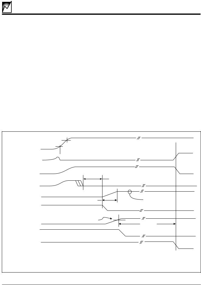
SEQUENCER AC OPERATING CHARACTERISTICS (Over Recommended Operating Conditions)
Symbol |
Parameter |
Notes |
Min. |
Typ. |
Max. |
Units |
|
|
|
|
|
|
|
tVTPD |
VTRIP to Power Down Delay |
Host Voltage Input |
|
1 |
5 |
µs |
tVTR |
VTRIP to RESET Output Delay |
Card Voltage Input |
|
1 |
5 |
µs |
tPRLPR |
PCI_RST# to LOCAL_PCI_RST# |
|
|
.1 |
1 |
µs |
VRVALID |
RESET Output Valid |
|
1 |
|
|
V |
TSLEW |
Slew Rate |
|
|
|
250 |
V/Sec |
THSE |
BD-SEL# to Power-on Delay |
BD_SEL# Noise filter |
100 |
150 |
200 |
ms |
tPURST |
Reset Timeout |
|
100 |
150 |
200 |
ms |
tGLTICH |
Glitch Reject Pulse Width |
|
|
|
40 |
ns |
tOCF |
Over-current to FAULT# |
|
|
1 |
|
µs |
tOCVG |
Over-current to VGATE Off |
|
|
1 |
|
µs |
tCBTC |
Circuit Breaker Time Constant |
Powering-on |
|
4 |
|
µs |
|
|
Operating |
|
16 |
|
µs |
|
|
|
|
|
|
|
|
|
|
|
2037 PGM T4.1 |
|
|
VCC |
VTRIP |
|
|
|
|
|
|
|
|
& |
VRVALID |
|
|
|
HST_3V_MON |
|
|
|
|
|
|
|
|
LOCAL_PCI_RST# |
|
|
|
|
|
RESET |
|
|
|
|
BD_SEL1# |
tHSE |
|
|
|
+ |
|
|
|
|
|
|
|
|
|
BD_SEL2# |
|
|
VGATE5 & VGATE3 |
|
|
||
|
|
|
tSLEW |
VOHVG |
|
|
DRVREN# |
|
|
|
CARD_5V_MON |
VTRIP |
|
|
|
|
& |
|
|
|
CARD_3V_MON |
|
tPURST |
|
|
|
|
|
|
|
|
HEALTHY# |
|
|
|
|
SGNL_VLD# |
|
|
|
|
|
|
2037 ILL3.0 |
|
|
|
Card Insertion Timing Diagram |
|
2037 |
8.4 |
10/26/00 |
4 |
|
|
|
|
|
|
SMH4042
VCC |
|
VTRIP |
|
or HST_3V_MON
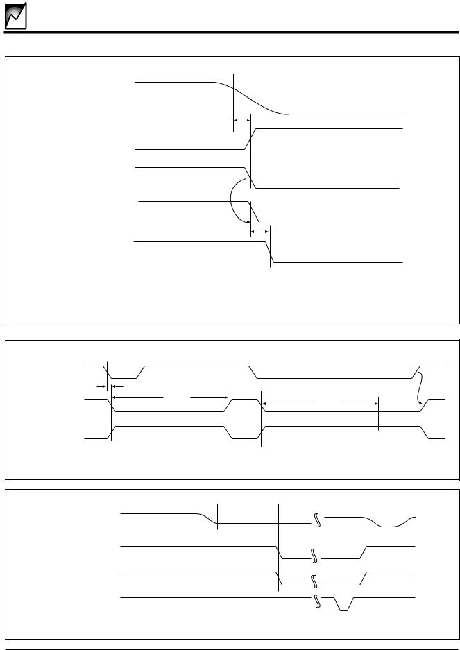
tVTPD
SGNL_VLD#
&
DRVREN#
VGATE5
&
VGATE3
CARD_5V_MON |
|
|
VTRIP |
|
|
||
or |
|
|
|
CARD_3V_MON |
|
|
|
|
|
|
tVTR
LOCAL_PCI_RST#
&
HEALTHY#
2037 ILL4.0
Loss of Voltage Timing Sequence
PCI_RST# |
|
|
tPRLPR |
|
tPURST |
LOCAL_PCI_RST# |
tPURST |
|
|
RESET |
|
|
2037 ILL5.0 |
|
Host Initiated Reset Timing Diagram |
 tCBTC
tCBTC 
CBI_5 or CBI_3
FAULT#
VGATE5 & VGATE3
PCI_RST#
2037 ILL6.0
Circuit Breaker Timing Diagram
2037 8.4 10/26/00
5

SMH4042
MEMORY AC OPERATING CHARACTERISTICS
TA = -40°C to +85°C |
|
2.7V to 4.5V |
4.5V to 5.5V |
|
|||
Symbol |
Parameter |
Conditions |
Min |
Max |
Min |
Max |
Units |
|
|
|
|
|
|
|
|
fSCL |
SCL Clock Frequency |
|
0 |
100 |
0 |
400 |
KHz |
|
|
|
|
|
|
|
|
tLOW |
Clock Low Period |
|
4.7 |
|
1.3 |
|
µs |
|
|
|
|
|
|
|
|
tHIGH |
Clock High Period |
|
4.0 |
|
0.6 |
|
µs |
|
|
|
|
|
|
|
|
tBUF |
Bus Free Time |
Before New Transmission |
4.7 |
|
1.3 |
|
µs |
|
|
|
|
|
|
|
|
tSU:STA |
Start Condition Setup Time |
|
4.7 |
|
0.6 |
|
µs |
|
|
|
|
|
|
|
|
tHD:STA |
Start Condition Hold Time |
|
4.0 |
|
0.6 |
|
µs |
|
|
|
|
|
|
|
|
tSU:STO |
Stop Condition Setup Time |
|
4.7 |
|
0.6 |
|
µs |
|
|
|
|
|
|
|
|
tAA |
Clock Edge to Valid Output |
SCL low to Valid SDA (cycle n) |
0.3 |
3.5 |
0.2 |
0.9 |
mµs |
|
|
|
|
|
|
|
|
tDH |
Data Out Hold Time |
SCL low (cycle n+1) to SDA change |
0.3 |
|
0.2 |
|
µs |
|
|
|
|
|
|
|
|
tR |
SCL and SDA Rise Time |
|
|
1000 |
|
300 |
ns |
|
|
|
|
|
|
|
|
tF |
SCL and SDA Fall Time |
|
|
300 |
|
300 |
ns |
|
|
|
|
|
|
|
|
tSU:DAT |
Data In Setup Time |
|
250 |
|
100 |
|
ns |
|
|
|
|
|
|
|
|
tHD:DAT |
Data In Hold Time |
|
0 |
|
0 |
|
ns |
|
|
|
|
|
|
|
|
TI |
Noise Filter SCL & SDA |
Noise Suppression |
|
100 |
|
100 |
ns |
|
|
|
|
|
|
|
|
tWR |
Write Cycle Time |
|
|
5 |
|
5 |
ms |
|
|
|
|
|
|
|
|
|
|
|
|
|
|
|
|
|
|
|
|
|
|
|
|
|
|
|
|
|
|
|
|
|
2037 PGM T5.1 |
|
|
|
tR |
|
|
|
|
|
|
|
tHIGH |
tLOW |
|
|
|
|
|
|
|
|
|
||||
|
|
|
|
|
|
tF |
|
|
|
|
|
|
|
|
|
|
|
|
|
|
|
|
|
||
|
|
|
|
|
|
|
|
|
|
|
|
|
|
|
|
|
|
|
|
|
|
|
|
||
|
|
SCL |
|
|
|
|
|
|
|
|
|
|
|
|
|
|
|
|
|
|
|
|
|
|
|
|
|
tSU:SDA |
|
|
tHD:SDA |
|
tHD:DAT |
|
|
|
|
tSU:DAT |
|
tSU:STO |
tBUF |
||||||||||
|
|
SDA In |
|
|
|
|
|
|
|
|
|
|
|
|
|
|
|
|
|
|
|
|
|
|
|
|
|
|
|
|
|
|
tAA |
|
|
|
|
|
|
|
tDH |
|
|
|
|
|
|
|
|
||
|
|
SDA Out |
|
|
|
|
|
|
|
|
|
|
|
|
|
|
|
|
|
|
|
|
|
|
|
|
|
|
|
|
|
|
|
|
|
|
|
|
|
|
|
|
|
|
|
|
|
|
|
|
2037 ILL11.0 |
|
|
|
S |
|
|
|
|
|
|
|
|
|
|
|
|
|
|
|
|
|
|
|
|
|
S |
|
|
|
T |
|
|
|
|
|
Typical Write Operation |
|
|
|
|
|
|
|
|||||||||
|
|
|
A |
|
|
|
|
|
|
|
|
|
|
|
|
T |
|||||||||
|
|
Master |
R |
|
|
|
|
|
|
|
|
|
|
|
|
|
|
|
|
|
|
|
|
|
O |
|
|
|
T |
|
|
|
|
|
|
|
|
|
|
|
|
|
|
|
|
|
|
|
|
|
P |
|
|
SDA |
A A B |
R |
A A A A A A A A |
D D D D D D D D |
D D |
D D |
|||||||||||||||||
|
|
2 1 |
0 |
/ |
7 6 |
5 |
4 |
3 |
2 |
1 |
0 |
7 |
6 |
5 |
4 |
3 |
2 |
1 |
0 |
7 |
6 |
1 |
0 |
||
|
|
|
|
|
W |
|
|
|
|
|
|
|
|
|
|
|
|
|
|
|
|
|
|
|
|
|
|
|
|
|
|
A |
|
|
|
|
|
|
|
A |
|
|
|
|
|
|
A |
|
|
|
A |
|
|
Slave |
|
|
|
C |
|
|
|
|
|
|
|
C |
|
|
|
|
|
|
C |
|
|
|
C |
|
|
|
|
|
|
|
|
|
|
|
|
K |
|
|
|
|
|
|
|
|
|
||||
|
|
|
|
|
|
K |
|
|
|
|
|
|
|
|
|
|
|
|
|
K |
|
|
|
K |
|
|
|
|
S |
|
|
|
|
Typical Read Operation |
|
|
|
|
|
|
|
S |
|||||||||
|
|
|
T |
|
|
|
|
|
|
|
|
|
|
|
|
|
|
|
|
|
|
|
|
|
|
|
|
Master |
A |
|
|
|
|
|
|
|
|
|
|
A |
|
|
|
|
|
|
A |
|
|
|
T |
|
|
|
R |
|
|
|
|
|
|
|
|
|
|
C |
|
|
|
|
|
|
C |
|
|
|
O |
|
|
|
T |
|
|
|
|
|
|
|
|
|
|
K |
|
|
|
|
|
|
K |
|
|
|
P |
|
|
SDA |
A A B |
R |
D D D D D D D D |
D D D D D D D D |
D D |
D D |
|||||||||||||||||
|
|
/ |
|||||||||||||||||||||||
|
|
|
2 1 |
0 |
W |
7 |
6 |
5 |
4 |
3 |
2 |
1 |
0 |
7 |
6 |
5 |
4 |
3 |
2 |
1 |
0 |
7 |
6 |
1 |
0 |
|
|
|
|
|
|
|
|
|
|
|
|
|
|
|
|
|
|
|
|
|
|
|
|
|
|
|
|
Slave |
|
|
|
A |
|
|
|
|
|
|
|
|
|
|
|
|
|
|
|
|
|
|
|
|
|
|
|
|
C |
|
|
|
|
|
|
|
|
|
|
|
|
|
|
|
|
|
|
|
|
|
|
|
|
|
|
K |
|
|
|
|
|
|
|
|
|
|
|
|
|
|
|
|
|
2037 ILL12.0 |
|
2037 |
8.4 |
10/26/00 |
|
|
|
|
|
|
|
|
|
6 |
|
|
|
|
|
|
|
|
|
|
|
|
|
|
|
|
|
|
|
|
|
|
|
|
|
|
|
|
|
|
|
|
|
|
|
|
|
|
|

SMH4042
PIN DESCRIPTIONS
CBI_5: CBI_5 is the circuit breaker input for the supply voltage. With a series resistor placed in the supply path between the 5V early power and CBI_5, the circuit breaker will trip whenever the voltage across the resistor exceeds 50mV.
DRVREN#: DRVREN# is an open-drain, active-low output that indicates the status of the 3 volt and 5 volt high side driver outputs (VGATE5 and VGATE3). This signal may also be used as a switching signal for the 12 volt supply.
FAULT#: FAULT# is an open-drain, active-low output. It will be driven low whenever an over-current condition is detected. It will be reset at the same time that the VGATE outputs are turned back on after a reset from the host on the PWR_EN pin.
1Vref: The 1Vref output provides a 1 volt reference for pre-charging the bus signal pins. Implementing a simple unity-gain amplifier circuit will allow pre-charging a large number of pins.
ISLEW: ISLEW is a Diode-connected NFET input. It may be used to adjust the 250V/s default slew rate of the highside driver outputs
VSEL: VSEL is a TTL level input used to determine which of the host power supply inputs will be monitored for valid voltage and reset generation. This is a static input and the pin should be tied to VCC or ground through a resistor.
VSEL-Voltage |
Host Voltage |
Select |
Monitored |
Low |
5 Volt or Mixed-Mode |
|
|
High |
3.3 Volt Only |
|
|
A0: Address 0 is not used by the memory array. It can be connected to ground or left floating. It must not be connected VCC.
A1, A2: Address inputs 1 and 2 are used to set the twobit device address of the memory array. The state of these inputs will determine the device address for the memory if it is on a two-wire bus with multiple memories with the same device type identifier. (For complete addressing information refer to the detailed memory operation section that follows.)
SCL: The SCL input is used to clock data into and out of the memory array. In the write mode, data must remain stable while SCL is HIGH. In the read mode, data is clocked out on the falling edge of SCL.
SDA: The SDA pin is a bidirectional pin used to transfer data into and out of the memory array. Data changing from one state to the other may occur only when SCL is LOW, except when generating START or STOP conditions. SDA is an open-drain output and may be wire-ORed with any number of open-drain outputs.
BD_SEL1# BD_SEL2#: These are active low TTL level inputs with internal pull-ups to VCC. When pulled low they indicate full board insertion. When used in a “non-High Availability” application these inputs will be the last connector pins to make contact with the host backplane. On the host side, the signals should be directly tied to ground. In a “High Availability” application these inputs can be the last pins to mate with the backplane. Alternatively, they can be actively driven by the host or be connected to switches interfaced to the board ejectors or any combination. Regardless, BOTH inputs MUST be low before the SMH4042 will begin to turn on the backend voltage.
GND: Ground should be applied at the same time as early-power.
HEALTHY#: HEALTHY# is an open-drain, active-low output indicating card side power inputs are above their reset trip levels.
SGNL_VLD#: SGNL_VLD# is an open-drain, active-low output that indicates card side power is valid and the internal card side PCI_RST# timer has timed out.
PWR_EN: PWR_EN is a TTL level input that allows the host to enable or disable the power to the individual card. During initial power up, this signal would start in a low state and then be driven high during software initialization. If this signal is driven low, the power supply control outputs will be driven into the inactive state, and the reset signals asserted. In a “non-High Availability” system this input can be tied high.
The PWR_EN input is also used to reset the SMH4042 circuit breakers. After an over-current condition is detected the VGATE outputs can be turned back on by first taking PWR_EN low then returning it high.
PCI_RST#: PCI_RST# is a TTL level input used as a reset input signal from the host interface. A high to low transition (held low longer than 40ns) will initiate a reset sequence. The LOCAL_PCI_RST# output and the RESET output will be driven active for a minimum period of tPURST. If the PCI_RST# input is held low longer than tPURST the reset outputs will continue to be driven until PCI_RST# is released.
2037 8.4 10/26/00
7

SMH4042
LOCAL_PCI_RST#: LOCAL_PCI_RST# is an opendrain active-low output. It is used to reset the backend circuitry on the add-in card. It is active whenever the cardside monitor inputs are below their respective VTRIP levels. It may also be driven low by a low input on the PCI_RST# pin.
LOCAL PCI_RST: LOCAL PCI_RST is an open-drain (PFET) active-high output. It operates in parallel with LOCAL_PCI_RST# providing an active high reset signal which is required by many 8051 style MCUs. It is active whenever the card-side monitor inputs are below their respective VTRIP levels. It may also be driven active by a low input on the PCI_RST# pin.
CARD_3V_MON: The CARD_3V_MON input monitors the card-side 3.3V supply. If the input falls below VTRIP, the HEALTHY# and SIGNL_VLD# outputs are de-as- serted and the reset outputs are driven active.
VGATE3: VGATE3 is a slew rate limited high side driver output for the 3.3V external power FET gate. The VGATE3 output-voltage is generated by an on-board charge pump.
HST_3V_MON: The HST_3V_MON input monitors the host 3.3 volt supply and it is used as a reference for the circuit breaker comparator. If VCC3 falls below VTRIP, SGNL_VLD# is de-asserted, the high side drivers are disabled and LOCAL_PCI_RST# is asserted.
CBI_3: CBI_3 is the circuit breaker input for the low supply. With a series resistor placed in the supply path between VCC3 and CBI_3, the circuit breaker will trip whenever the voltage across the resistor exceeds 50mV.
CARD_5V_MON: The CARD_5V_MON input monitors the card-side 5V supply. If the input falls below VTRIP, the HEALTHY# and SIGNL_VLD# outputs are de-asserted and the reset outputs are driven active.
VGATE5: VGATE5 is a slew rate limited high side driver output for the 5V external power FET gate. The output voltage is generated by an on-board charge pump.
VCC: VCC is the power supply pin for the SMH4042 This input is monitored for power integrity. If it falls below the 5V sense threshold (VTRIP) and the VSEL input is low, the SGNL_VLD# HEALTHY# signals are de-asserted, the high side drivers disabled and reset outputs are
asserted. On a CompactPCI board, this must be connected to early power.
DEVICE OPERATION
Power-Up Sequence
The SMH4042 is an integrated power controller for any hot swappable add-in card. The SMH4042 provides all the signals and control functions to be compatible with CompactPCI Hot Swap requirements for basic hot swap systems, full hot swap boards and high availability systems.
Insertion Process
As the add-in board is inserted into the backplane physical connections should be made with the chassis in order to properly discharge any voltage potentials to ground. The board will first contact the long pins on the backplane that provide early power (+5V, +3.3V and ground). Depending upon the board configuration early power should be routed to the VCC pin of the SMH4042. As soon as power is applied, the SMH4042 will assert the reset outputs to the backend circuits, turn off the VGATE3/5 outputs (disabling the external power FETS) and begin outputting the 1-volt Vref. The 1-volt reference can be used to precharge the I/O pins before they begin to mate with the bus signals. The open collector HEALTHY# output will be deasserted, It should be actively pulled high by an external pull-up resistor (minimum 10K ohm).
The next pins to mate are the I/Os and the balance of the power pins, if they are not already mated. The I/Os will have been pre-charged by the Vref output of the SMH4042.
The BD_SEL# pins are the last inputs to be driven to their true state. In most systems these will most likely be driven to ground when the short pins are mated. This would indicate the card is fully inserted and the power-up sequence can begin. If, however, the design is based on high availability requirements the two pins can be actively driven by the host or combined with a switch input indicating the ejector handles are fully engaged.
Sequencing
Once the proper card insertion has been assured, the SMH4042 will check the status of the Power Enable signal from the host. This input can be used to power down individual cards on the bus via software control; it must by held high in order for the SMH4042 to enable power sequencing to the card.
Once these conditions are met, the SMH4042 will drive the VGATE3 and VGATE5 outputs to turn on the external 3 volt and 5 volt power FETs. The slew rate of these outputs is controlled using on board circuitry and results in a slew rate of 250V/s. Different slew rates can be
2037 8.4 10/26/00
8

SMH4042
accommodated by either adding an additional capacitor between the MOSFET gate and ground or by injecting current into the ISLEW input. All circuitry on the card is held in a reset condition until the 5 volts (or 3.3 volt) supply is stable and the reset interval timer has timed out the 150ms reset time. At this point, the reset signals are deasserted, and proper operation of the card commences.
The SMH4042 will monitor the card’s backend voltages. Once they are at or above the CARD VTRIP levels, the SMH4042 will drive the HEALTHY# output.
Card Removal Process
The card removal process operates in the opposite sequence. For non-high-availability cards, the action of card removal disconnects the BD_SEL# (short pins) from ground and the SMH4042 will instantly shutdown the VGATE outputs, change the HEALTHY# status and assert the LOCAL_PCI_RST# output.
Because connectors to the host backplane employ the staggered pins, power will still be applied to the SMH4042 and the I/O interface circuits. The LOCAL_PCI_RST# signal will place the interface circuits into a high impedance condition. The pre-charge voltage will be applied to the I/Os enabling a graceful disengagement from the active bus. Once the I/O pins are free of the backplane power can then be removed from the SMH4042 and other early power devices by releasing the long pins.
The removal process is slightly different for a high-avail- ability system. As the ejector handle is rotated the ejector switch will open, causing a change of state that will activate the ENUM# signal to the host. In response to this notification the host will de-assert a hardware controlled BD_SEL# signal. This action will turn on an indicator LED on the card, notifying the operator it is now safe to proceed with the removal of the card. The sequence will then follow that outlined for the non-high-availability removal process.
Power Configurations
The SMH4042 can be used in 5V-only, 3.3V-only and mixed voltage systems. For mixed voltage systems, simply connect the appropriate bus and card power inputs as indicated. The VSEL pin should be grounded.
For systems with a single power supply, connect VCC and HST_3V_MON together to the bus power line. Also connect CARD_3V_MON and CARD_5V_MON together to the card side power. Now the state of VSEL determines
the reset level that will be used to signal valid power. For 3.3V systems, tie VSEL to VCC, for 5V systems, tie VSEL to ground.
MONITORING POWER SUPPLY HEALTH
Monitor Inputs
The SMH4042 has a total of six comparators that are used to monitor the health of the host platform supplies and the card-side (backend) voltages. In hot swap applications each supply going to the backend logic needs to be monitored at three points.
The first point is at the source on the host connector, VCC and HST_3V_MON. If this voltage is not within specification, then the down stream sequencing of powering-on the backend logic will not proceed.
The next stage (the CBI inputs) is one step closer to the backend logic to monitor the current flowing into the backend logic. This can not exceed the specification; however, If it does, then the SMH4042 must turn off the source to the backend logic.
The CARD_5V_MON and CARD_3V_MON inputs are used to sense the actual voltage level in the backend logic. If either comparator detects a low voltage condition the backend logic will be placed in a reset condition (LOCAL_PCI_RST# asserted), but the VGATE outputs will remain active so long as the host voltage and current sense are valid.
VCC vs. HST_3V_MON
The VCC input is the supply input and in a CompactPCI application this pin must connect to an early power pin on the host connector. The HST_3V_MON input is strictly a voltage monitoring input, it is not a supply input. The operating supply voltage range on the VCC pin is 2.7V to 5.5V, but it will only monitor a 5V supply. This is not an
2037 8.4 10/26/00
9
 Loading...