


Sub-Zero IT36CILH, IC36FILH, IT30CIIDRH, IT30FILH, IC36RRH Installation manual
...Integrated Refrigeration Installation Guide
INTEGRATED REFRIGERATION
Contents
3Integrated Refrigeration
4Opening Dimensions
5Electrical
5Plumbing
6Preparation
6 Anti-Tip Bracket
8 Placement
8Alignment
9Water Line
10Custom Panels
12 Panel Installation
14 Completion
Features and specifications are subject to change at any time without notice. Visit subzero.com/specs for the most up-to-date information.
Important Note
To ensure this product is installed and operated as safely and efficiently as possible, take note of the following types of highlighted information throughout this guide:
IMPORTANT NOTE highlights information that is especially important.
CAUTION indicates a situation where minor injury or product damage may occur if instructions are not followed.
WARNING states a hazard that may cause serious injury or death if precautions are not followed.
IMPORTANT NOTE: Throughout this guide, dimensions in parentheses are millimeters unless otherwise specified.
IMPORTANT NOTE: Save these instructions for the local electrical inspector.

INTEGRATED REFRIGERATION
Product Information
Important product information including the model and serial number are listed on the product rating plate. For column models, the rating plate is located inside the middle drawer near the drawer guide opposite the hinge. For tall and drawer models, the rating plate is located inside the cabinet, to the left of the upper drawer. Refer to the illustrations below.
If service is necessary, contact Sub-Zero factory certified service with the model and serial number. For the name of the nearest Sub-Zero factory certified service or for
questions regarding the installation, visit the contact & support section of our website, subzero.com or call Sub Zero customer care at 800-222-7820.
RATING |
PLATE |
RATING |
PLATE |
Column models. |
Tall and drawer models. |
Tools and Materials
•Screwdrivers—standard, Phillips and Torx.
•Power drill.
•Drill bits (masonry bits required for concrete installation).
•Standard socket and wrench set.
•2' and 4' levels.
•Tubing cutter.
•3' (.9 m) of 1/4" OD copper, braided stainless steel or PEX tubing.
•Saddle valve.
•Material to protect home, flooring and cabinetry during installation.
subzero.com | 3
SITE PREPARATION
Opening Dimensions
INTEGRATED MODELS
|
25" (635) |
|
OPENING |
|
DEPTH |
|
TOP VIEW |
H |
W |
OPENING |
OPENING WIDTH |
HEIGHT |
|
SIDE VIEW |
FRONT VIEW |
NOTE: 31/2" (89) finished returns will be visible and should be finished to match cabinetry.
|
|
|
|
|
|
|
|
|
3/4" |
|
|
|
|
|
|
|
|
|
|
|
|
|
|
|
|
|
|
|
|
|
|
|
|
|
|
|
|
|
|
|
|
||
|
|
|
|
|
|
|
(19) |
|
|
|
|
|
|
|
|
|
|
|
|
||
|
|
|
|
|
|
|
|
TYPICAL |
|
|
|
|
|
|
|
|
|
|
|
|
|
31/2" (89) |
|
|
|
|
|
|
31/2" (89) |
|
|
|
|
|
|
||||||||
FINISHED |
|
|
|
|
|
|
|
FINISHED |
|
|
|
FILLER |
|||||||||
|
|
|
|
|
|
|
|
|
|
||||||||||||
RETURN |
|
|
|
|
|
|
|
RETURN |
|
|
|
|
|||||||||
|
|
|
|
|
|
|
|
|
|
|
|||||||||||
|
|
|
|
|
|
|
|
|
|
|
|
|
|
|
|
|
|
|
|
|
|
W |
|
|
|
|
|
|
|
|
|
W |
|
|
|
|
|
|
|
|
|||
|
|
|
|
|
|
|
|
|
|
|
|
|
|
|
|
|
|
||||
|
|
|
|
|
|
|
|
|
|
|
|
|
|||||||||
|
|
|
|
|
|
|
|
|
|||||||||||||
|
|
|
|
|
|
|
|
|
|
|
|
|
|
|
|
|
|
|
|||
FRAMELESS CABINETRY |
|
|
|
FRAMED CABINETRY |
|||||||||||||||||
OPENING DIMENSIONS
COLUMN |
W |
H |
IC-18FI |
18" (457) |
84" (2134) |
IC-24R, IC-24FI |
24" (610) |
84" (2134) |
IC-30R(ID), IC-30FI |
30" (762) |
84" (2134) |
IC-36R(ID) |
36" (914) |
84" (2134) |
TALL |
W |
H |
IT-30R(ID), IT-30FI, IT-30CI(ID) |
30" (762) |
84" (2134) |
IT-36R(ID), IT-36CI(ID) |
36" (914) |
84" (2134) |
DRAWER |
W |
H |
ID-24R, ID-24F(I) |
24" (610) |
341/2" (876) |
ID-27R |
27" (686) |
341/2" (876) |
ID-30R(P), ID-30F(I), ID-30C(I) |
30" (762) |
341/2" (876) |
ID-36R(P), ID-36C(I) |
36" (914) |
341/2" (876) |
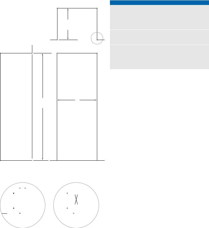
The depth of each integrated model is 24" (610). Allow for panel thickness when planning the finished opening depth. A minimum 31/2" (89) finished return is required on all sides of the opening. Framed cabinets will require additional finished filler material behind the face frame for a proper installation. Refer to the illustration.
DUAL INSTALLATION
When installing two units side by side in a dual installation, the opening width is the width of the two units added together. A dual installation kit will be required for this installation. If a dual installation kit is not specified, a minimum 2" (51) filler strip is required between units.
Dual installation kits are available through an authorized Sub-Zero dealer. For local dealer information, visit the find a showroom section of our website, subzero.com. For questions regarding the installation, call Sub Zero customer care at 800-222-7820.
4 | Sub-Zero Customer Care 800.222.7820

SITE PREPARATION
Electrical
Installation must comply with all applicable electrical codes.
The electrical supply must be located within the shaded area shown in the illustration and chart below. A separate circuit, servicing only this appliance is required. A ground fault circuit interrupter (GFCI) is not recommended and may cause interruption of operation.
The electrical outlet must be positioned with the grounding prong to the right of the thinner blades.
 CAUTION
The outlet must be checked by a qualified electrician to be sure that it is wired with the correct polarity. Verify that the outlet is properly grounded.
 WARNING
Do not use an extension cord, two-prong adapter or remove the power cord ground prong.
ELECTRICAL REQUIREMENTS |
|
Electrical Supply |
115 VAC, 60 Hz |
Service |
15 amp |
Receptacle |
3-prong grounding-type |
ELECTRICAL SUPPLY LOCATION |
|
WIDTH |
A |
18" Models |
6" (152) |
24" Models |
91/2" (241) |
27" Models |
11" (279) |
30" Models |
121/2" (318) |
36" Models |
151/2" (394) |
Plumbing
Installation must comply with all applicable plumbing codes.
The water supply line should be located within the shaded area shown in the illustration below. The water supply line should be connected to the house supply with an easily accessible shut-off valve. Do not use self piercing valves. The water supply line must be flush to the floor and not interfere with installation of the anti-tip bracket.
Column and tall models with an ice maker or water dispenser feature a water filtration system. An in-line filter is required for drawer models with an ice maker when water conditions have a high sediment content.
A reverse osmosis system can be used provided there is constant water pressure of 35–120 psi (2.4–8.3 bar) supplied to the unit at all times. In this application, the water filtration system must be bypassed. Refer to water filter bypass on page 15. A copper line is not recommended for this application.
PLUMBING REQUIREMENTS |
|
Water Supply Line |
1/4" OD copper, braided |
|
stainless steel or PEX tubing |
Water Pressure |
35–120 psi (2.4–8.3 bar) |
Excess Water Line for Connection |
36" (914) |
WATER SUPPLY LOCATION |
|
WIDTH |
A |
18" Models |
3" (76) |
24" Models |
51/2" (140) |
30" Models |
6" (152) |
36" Models |
9" (229) |
|
LEFT SIDE |
OF OPENING |
|
41/2" |
A |
(114) |
|
|
41/4" |
|
(108) |
1/4" (6) |
FLOOR |
|
|
Electrical supply location.
RIGHT SIDE |
|
OF OPENING |
|
A |
6" (152) |
3" (76) |
|
AREA EXTENDS 1/2" (13) |
|
FORWARD ON FLOOR |
|
Water supply location.
subzero.com | 5

SITE PREPARATION
Preparation
Uncrate the unit and inspect for damage. Remove the wood base and discard shipping bolts and brackets. Remove and recycle packing materials. Do not discard the kickplate, antitip bracket and hardware.
Remove the kickplate by extracting the two mounting screws. Refer to the illustration below.
SCREW |
Kickplate removal.
Anti-Tip Bracket
 WARNING
To prevent the unit from tipping forward, the anti-tip bracket must be installed.
The back of the anti-tip bracket must be installed 24" (610) from the front of the unit (without panels).
Use all anti-tip bracket hardware as instructed for wood or concrete floors.
IMPORTANT NOTE: For wood or concrete floor applications, if the #12 screws do not hit a wall stud or wall plate, use the #8 screws and #12 washers with the wall anchors.
IMPORTANT NOTE: In some installations the subflooring or finished floor may necessitate angling the screws used to fasten the anti-tip bracket to the back wall.
ANTI-TIP HARDWARE
1 Anti-tip bracket
12 #12 x 21/2" pan head screws
4 3/8"–16 x 33/4" wedge anchors
12 #12 flat washers
4 #8–18 x 11/4" truss head screws
4 Nylon Zip-it® wall anchors
6 | Sub-Zero Customer Care 800.222.7820

SITE PREPARATION
Anti-Tip Bracket
WOOD FLOOR APPLICATION
After properly locating the anti-tip bracket in the opening, drill pilot holes 3/16" (5) diameter maximum in the wall studs or wall plate. Use the #12 screws and washers to secure the brackets. Verify the screws penetrate through the flooring material and into wall studs or wall plate a minimum of 3/4" (19). Refer to the illustration and chart below.
CONCRETE FLOOR APPLICATION
After properly locating the anti-tip bracket in the opening, drill pilot holes 3/16" (5) diameter maximum in the wall studs or wall plate. Drill 3/8" (10) diameter holes into the concrete a minimum of 11/2" (38) deep. Use the #12 screws and washers to secure the brackets to the wall, and use the 3/8" wedge anchors to secure the brackets to the floor. Verify the screws penetrate wall studs or wall plate a minimum of 3/4" (19). Refer to the illustration and chart below.
ANTI-TIP BRACKET PLACEMENT
WIDTH |
A |
18" Models |
9" (229) |
24" Models |
12" (305) |
27" Models |
131/2" (343) |
30" Models |
15" (381) |
36" Models |
18" (457) |
CONCRETE WEDGE ANCHOR INSTALLATION:
1Drill a 3/8" (10) diameter hole any depth exceeding the minimum embedment. Clean the hole or drill additional depth to accommodate drill fines.
2Assemble the washer and nut flush with the end of anchor to protect threads. Drive the anchor through the material to be fastened until the washer is flush with the surface material.
3Expand the anchor by tightening the nut 3–5 turns past hand-tight position or to 25 foot-pounds of torque.
 WARNING
Verify there are no electrical wires or plumbing in the area which the screws could penetrate.
 CAUTION
Always wear safety glasses and use other necessary protective devices or apparel when installing or working with anchors.
Anchors are not recommended for use in lightweight masonry material such as block or brick, or for use in new concrete which has not had sufficient time to cure. The use of core drills is not recommended to drill holes for the anchors.
A |
A |
|
|
|
FINISHED |
|
FLOORING |
WALL PLATE |
|
SUBFLOORING |
|
WOOD FLOOR
A |
A |
|
|
|
FINISHED |
|
FLOORING |
WALL PLATE |
|
SUBFLOORING |
|
CONCRETE |
11/2"(38) |
FLOOR |
min |
|
Wood floor. |
Concrete floor. |
subzero.com | 7

INSTALLATION
Placement
 CAUTION
Before moving the unit into position, secure the door/ drawers closed and protect any finished flooring.
Use an appliance dolly to move the unit near the opening. The front leveling legs are extended below the front rollers to improve stability during placement. Once the unit is placed in front of the opening, completely retract the front leveling legs to allow the unit to be rolled into position. Front and rear leveling legs can be adjusted from the front once the unit is positioned.
If the unit has been on its back or side, it must stand upright for a minimum of 24 hours before connecting power.
Plug the power cord into the grounded outlet and roll the unit into position. Verify the anti-tip bracket is properly engaged.
Alignment
LEVELING
Once the unit is in position, height adjustment can be made from the front. Using a Phillips drive, turn clockwise to raise the unit or counterclockwise to lower. Use the lowest torque setting when using a power drill. Do not turn the leveling legs by hand. Refer to the illustration below.
When the unit is properly leveled, door/drawer adjustments are less likely to be necessary.
IMPORTANT NOTE: Level the unit to the floor, not surrounding cabinetry. This could affect the operation of the unit, such as door closing.
 WARNING
To reduce the possibility of the unit tipping forward, the front leveling legs must be in contact with the floor.
FRONT |
ADJUSTMENT |
REAR |
ADJUSTMENT |
Leveling. |
8 | Sub-Zero Customer Care 800.222.7820

INSTALLATION
Alignment
DEPTH ADJUSTMENT
Adjust the depth of the unit to fit flush with surrounding cabinetry. Follow these steps for a precision fit:
1Place decorative panel on a protected work surface. Place the panel thickness gauge next to the panel to determine which notch corresponds with the panel thickness. Refer to the illustration below. Once the proper notch has been determined, mark that notch with a marker.
2With the door closed, position the top of the unit using the panel thickness gauge. Refer to the illustration below. Insert a #8 x 1/2" stainless steel screw above the hinge, then insert a #8 x 1/2" pan head screw on the handle side of the unit. For narrower units, the door may need to be opened to access the handle side screw location. Repeat the process to align the bottom.
ANCHORING
Once the top and bottom are aligned, verify doors and drawers open properly, then install remaining screws in each side trim.
SCREW
SIDE TRIM
CABINETRY
FACE
FRAME
FRONT OF
UNIT
PANEL THICKNESS
GAUGE
Panel thickness. |
Unit depth. |
Water Line
Purge the water line prior to final connection to the unit. This will remove any debris that may be present in the tubing from installing the new water line. Connect the plastic tubing from the unit to the house water supply line with the fitting connection kit provided. Check all water line fittings for leaks.
Locate the water line in the notch as shown in the illustration below.
IMPORTANT NOTE: If a reverse osmosis system used, it is recommended that the water filtration system be bypassed by removing the filter.
IMPORTANT NOTE: Water lines can not be exposed to freezing temperatures.
NOTCH |
WATER LINE |
CONNECTION |
Water line.
subzero.com | 9

PANEL INSTALLATION
Custom Panels
For integrated models, custom door panels and handle hardware must be installed. Stainless steel panels are available through an authorized Sub Zero dealer. For local dealer information, visit the find a showroom section of our website, subzero.com.
The thickness of the custom panel can vary. A minimum 5/8" (16) thick panel is required, but the thickness can be increased provided it does not exceed the maximum panel weight indicated in the chart below. The depth of each integrated model is 24" (610). Allow for panel thickness when planning the finished opening depth.
PANEL REQUIREMENTS
PANEL WEIGHT |
MAX |
18" Column |
45 lb (20 kg) |
24" Column |
60 lb (27 kg) |
30" Column |
75 lb (34 kg) |
36" Column |
75 lb (34 kg) |
PANEL WEIGHT |
MAX |
30" Tall (door) |
50 lb (22 kg) |
36" Tall (door) |
60 lb (27 kg) |
Drawer |
15 lb (7 kg) |
PANEL THICKNESS |
MIN |
All Panels |
5/8" (16) |
Reveals between panels can vary, 1/8" (3) reveals are typical.
 CAUTION
When installing a panel thicker than 1" (25), the 90° stop may be required to prevent damage to the unit and adjacent cabinetry.
 CAUTION
As reveals between cabinetry and the unit decrease, severe finger pinching can occur while door is closing.
Finish all sides of custom panels. They will be visible when the door/drawer is open.
D-style handles are recommended. Door handles must be located near the edge of the panel opposite the hinge and should be centered top to bottom. Drawer handles must be located near the top edge of each panel. Stainless steel tubular and pro handles are available through an authorized Sub-Zero dealer. For local dealer information, visit the find a showroom section of our website, subzero.com.
10 | Sub-Zero Customer Care 800.222.7820
PANEL INSTALLATION
Custom Panels
DOOR PANEL HEIGHT
The height of the custom door panel can extend beyond the typical panel height, provided it does not exceed the weight limit. Refer to the illustration below.
|
13/4" |
|
(45) |
|
A DECORATIVE VALANCE |
1/8" (3) |
CANNOT EXTEND |
BEYOND THIS PLANE |
|
|
DOOR |
|
PANEL |
84" |
24" (610) |
(2134) |
TO BACK OF UNIT |
|
HINGE |
Upper valance (column and tall models)—side view.
TOE KICK CLEARANCE
The height of the toe kick area can extend beyond the typical toe kick height, provided it does not exceed the dimensions in the illustration below. Toe kick heights from 2" (51) to 37/8" (98) require a reduced toe kick accessory available through an authorized Sub-Zero dealer. For local dealer information, visit the find a showroom section of our website, subzero.com. For questions regarding the installation, call Sub Zero customer care at 800-222-7820.
HINGE |
VENTED |
|
LOUVERS |
|
24" (610) |
|
TO BACK OF UNIT |
DOOR |
|
PANEL |
|
|
11/8" (29) |
|
MAX |
|
TOE KICK |
|
ADJUSTMENT |
2" (51)* |
A DECORATIVE TOE KICK |
TO |
|
6" (152) |
CANNOT EXTEND |
FROM |
BEYOND THIS PLANE |
FLOOR |
|
*2" (51) to 3 7/8" (98) requires sales accessory. |
|
Toe kick—side view.
subzero.com | 11

PANEL INSTALLATION
Panel Installation
DOOR PANEL INSTALLATION
Typical panel dimensions are based on an 84" (2134) finished height with 1/8" (3) reveals. Template placement must be adjusted for panels exceeding typical dimensions.
For tall models, the door panel should be installed first, followed by the upper then lower drawer panel.
Place the panel face down on a protected work surface. Position the template flush with the top and sides of the panel. Verify the correct side of the template is being used, then mark and drill holes. Refer to the illustration below.
For tall models, align the notch in the template with the bottom of the door panel, then mark and drill holes. Refer to the illustration below.
TOP OF DOOR PANEL
TOP OF
DOOR PANEL 84" APPLICATION 83 7/8" ACTUAL
DOORPANEL
BOTTOMOF
USE TABS FOR HINGE
SIDE PANEL EDGE ON
DUAL INSTALLATION
Door panel template—top.
DUALINSTALLATION
SIDEPANELEDGEON
USETABSFORHINGE
BOTTOM OF
DOOR PANEL
BOTTOM OF
DOOR PANEL
837/8"ACTUAL
84"APPLICATION
DOORPANEL
TOPF
Door panel template—bottom (tall models only).
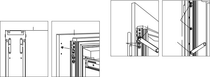
Use the T-20 torx drive provided to partially insert a #8 x 1/2" screw into the second hole from the top on each side of the panel. The screws should be approximately 3/16" (4) proud of the panel and will support the weight of the panel during installation.
Align the support screws on the back of the panel with the slotted holes on both door mounting brackets. Opening the door slightly may help with alignment. Once the panel is supported by the screws, partially insert a #8 x 1/2" screw into the second hole from the bottom on each side of the panel, but do not tighten.
 CAUTION
As the reveal between cabinets and the unit decreases, the potential exists for severe finger pinching if fingers are placed in the opening when the door is closing.
BACK OF
DOOR PANEL
Door panel mounting.
12 | Sub-Zero Customer Care 800.222.7820
PANEL INSTALLATION
Panel Installation
DRAWER PANEL INSTALLATION
Place the panel face down on a protected work surface. Position the template flush with the top and sides of the panel. Verify the correct side of the template is being used, then mark and drill holes. Refer to the illustration below.
Use the T-20 torx drive provided, to partially insert a #8 x 1/2" screw into the second hole from the top on each side of the panel. The screws should be approximately 3/16" (4) proud of the panel and will support the weight of the panel during installation.
Align the support screws on the back of the panel with the slotted holes on both drawer mounting brackets. Refer to the illustration below. Opening the drawer slightly may help with alignment. Once the panel is supported by the screws, partially insert a #8 x 1/2" screw into the second hole from the bottom on each side of the panel, but do not tighten.
|
TOP OF DRAWER PANEL |
BACK OF |
|
|
DRAWER PANEL |
|
TOP OF |
|
|
DRAWER PANEL |
|
|
TOP HOLES |
|
|
FOR UPPER |
|
|
AND LOWER |
|
|
DRAWERS |
|
OF DRAWER PANEL |
DRA OF EDGE LEFT |
|
Drawer panel template—top. |
Drawer panel mounting. |
PANEL ADJUSTMENT
Close the door and/or drawers, now adjustments can be made to align panels and reveals.
For side-to-side adjustment, move panels side to side, then install and tighten all mounting screws.
For up-and-down and in-and-out adjustments, slightly loosen the bracket screws. Depending on the level of adjustment required, it may be helpful to loosen all of the bracket screws which will allow for maximum adjustment. Once the bracket screws are loosened, rotate the cams to make adjustments. After adjustments have been made, tighten all bracket screws. Refer to the illustrations below.
BRACKET
IN-AND-OUT SCREWS
CAM
UP-AND-DOWN
CAM
BRACKET
SCREWS
In-and-out adjustment. |
Up-and-down adjustment. |
subzero.com | 13

INSTALLATION
Completion
DOOR TRIM INSTALLATION
After panels have been adjusted, install the decorative side trim to the door/drawers. To install, start at the top and align the trim with the front and rear flanges on the bracket, then snap into place by pushing the trim toward the back of the panel. Once the top is secure, continue the installation downward until the remaining trim is completely secure. Refer to the illustrations below.
DOOR TRIM
FRONT
FLANGE
REAR
FLANGE
TOP TRIM INSTALLATION
Identify the top trim strips by the notch on one end at the bottom; this trim strip fits on the hinge side of the unit.
Insert the outer end of each trim strip behind the vertical side trim. Engage the snap in the plastic side bracket and slide the panel as far to the outside as possible. Refer to the illustration below.
Rotate the inner end of each panel into the side flange of the center shroud, next to the water filter access door. Press on the trim strip to snap into place. Refer to the illustration below.
Door trim. Bracket flanges.
SIDE TRIM INSTALLATION |
Inner top trim. |
Outer top trim. |
|
Install the decorative trim strip to the handle side of tall and column models. The side trim snaps over the bracket attached to the handle side of the unit. Refer to the illustration below.
Side trim.
14 | Sub-Zero Customer Care 800.222.7820
 Loading...