


Sub-Zero ICBBI36UFDIDSPH, ICBBI36FSPHLH, ICBBI-42UFDID/S/PH, ICBBI-42UFDID/S/TH, ICBBI48SDSPH Installation Guide
BUILT-IN REFRIGERATION
INSTALLATION GUIDE
GUÍA DE INSTALACIÓN
GUIDE D’INSTALLATION
GUIDA ALL’INSTALLAZIONE
INSTALLATIONSANLEITUNG

BUILT-IN REFRIGERATION
Contents
2Built-In Refrigeration
3Opening Dimensions
5 Dual Installation
5 Electrical
5 Plumbing
5Preparation
6Anti-Tip Bracket
7Placement
7 Water Line
7 Custom Panels
9 Alignment
9 Completion
Important Note
To ensure this product is installed and operated as safely and efficiently as possible, take note of the following types of highlighted information throughout this guide:
IMPORTANT NOTE highlights information that is especially important.
CAUTION indicates a situation where minor injury or product damage may occur if instructions are not followed.
WARNING states a hazard that may cause serious injury or death if precautions are not followed.
Product Information
Important product information including the model and serial number of the unit are listed on the product rating plate. The rating plate is located at the top frame of the unit, inside the door. Refer to the illustration below.
If service is necessary, contact your authorized Sub-Zero dealer.
RATING
PLATE
Rating plate location.
Tools and Materials
•Screwdrivers—standard and Phillips.
•Power drill.
•Drill bits (masonry bits required for concrete installation).
•Torx drives—T-10, 15 and 20.
•Standard Allen wrench set.
•Standard socket and wrench set.
•.6 m and 1.2 m levels.
•Tubing cutter.
•.9 m of 1/4" OD copper, braided stainless steel or PEX tubing.
•Saddle valve.
•Material to protect home, flooring and cabinetry during installation.
2 | English
SITE PREPARATION
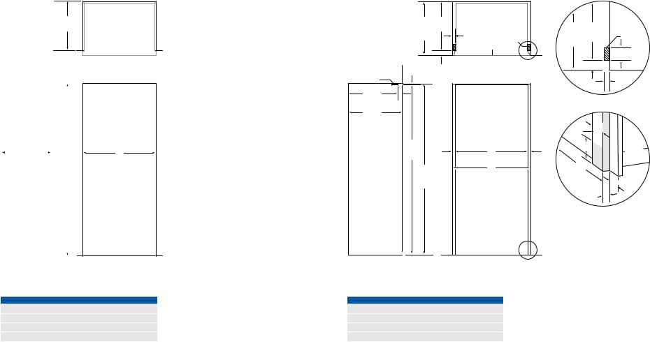
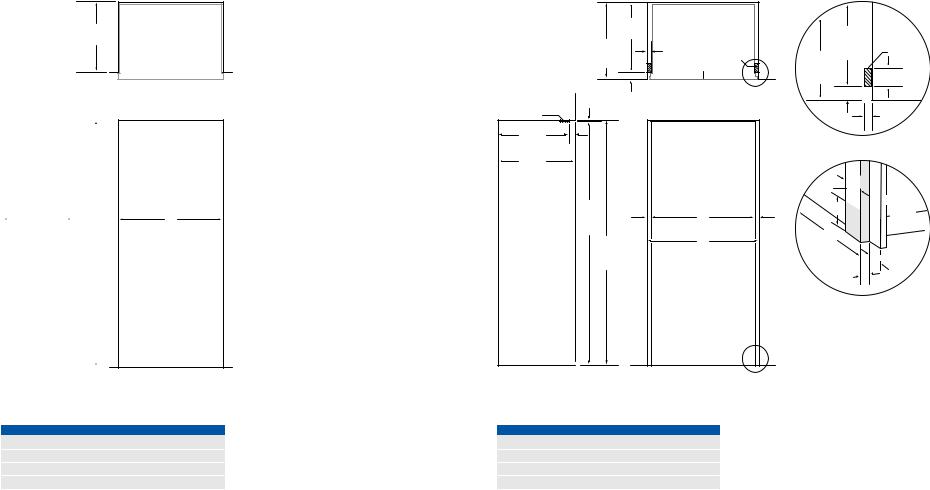
Opening Dimensions
STANDARD INSTALLATION
TOP VIEW
610 mm
OPENING
DEPTH
|
|
|
|
|
|
|
|
|
|
|
610 mm |
|
|
|
|
|
|
|
|
|
|
|
2127 mm |
|||
|
|
|
||||||
|
OPENING DEPTH |
|
|
OPENING |
||||
|
|
|
|
|
|
HEIGHT |
||
|
|
|
|
|
|
|
|
|
|
|
|
|
|
|
|
|
|
|
|
|
|
|
|
|
|
|
SIDE VIEW
A |
OPENING WIDTH |
FRONT VIEW
Opening Dimensions |
|
|
|
|
|
|
|
FLUSH INSET INSTALLATION |
|
|
|
|
|
|
|
|
|
|
TOP VIEW |
|
|
|
|
665 |
610 mm |
|
|
|
|
|
|
mm |
DEPTH |
|
|
|
665 |
610 mm |
TOP VIEW |
FLUSH TO CLEAT |
|
|
|
mm |
OPENING |
|
|
INSET |
|
32 mm |
|
|
FLUSH |
DEPTH |
CLEAT |
DEPTH |
|
|
|
||||
|
|
CLEAT |
INSET |
TO CLEAT |
|||
|
|
|
UNIT WITH |
|
|||
|
|
|
|
DEPTH |
|
|
|
|
|
19 mm PANEL |
|
|
|||
|
|
|
|
|
|||
|
|
|
|
|
|
|
76 mm |
|
|
|
|
DETAIL A |
|
|
typical |
|
|
|
|
|
|
|
|
|
56 mm |
|
|
|
|
56 mm |
|
6 mm |
|
|
|
|
|
|
|
|
|
|
|
|
|
|
|
CLEAT |
|
|
|
|
|
|
32 mm |
|
|
|
|
|
|
|
|
610 mm |
|
|
|
|
Detail A |
|
|
DEPTH TO CLEAT |
|
|
|
|
|
|
|
56 |
|
|
|
|
|
|
|
mm |
|
|
|
|
|
|
|
665 mm |
|
|
|
|
|
|
|
FLUSH INSET DEPTH |
|
|
|
|
|
|
|
|
|
|
|
|
|
76 mm |
|
|
|
|
|
|
CLEAT |
typical |
|
|
|
|
|
|
|
|
|
2127 |
|
|
|
|
|
102 |
SHADED |
|
|
|
|
|
AREA |
||
mm |
|
|
A |
|
|
mm |
MUST BE |
HEIGHT |
|
|
|
|
|
||
TO CLEAT |
32 |
WIDTH TO CLEAT |
32 |
|
FINISHED |
||
|
mm |
|
|
|
mm |
|
|
2134 |
|
|
B |
|
610 mm |
|
|
|
|
|
OPENING |
|
|||
mm |
|
FLUSH INSET WIDTH |
|
||||
|
DEPTH TO |
|
|||||
FLUSH |
|
|
|
|
|
||
|
|
|
|
CLEAT |
|
|
|
INSET |
|
|
|
|
|
56 mm |
|
|
|
|
|
|
|
||
HEIGHT |
|
|
|
|
|
|
|
|
|
|
|
|
|
|
|
|
|
|
|
|
|
32 mm |
|
|
|
|
|
|
Detail B |
|
|
|
|
|
|
DETAIL B |
|
|
|
SIDE VIEW |
FRONT VIEW |
OPENING WIDTH |
A |
If two units are installed side by side, refer to page 4. |
OPENING WIDTH |
A |
B |
762 mm Model |
746 mm |
|
762 mm Model |
746 mm |
813 mm |
914 mm Model |
902 mm |
|
914 mm Model |
902 mm |
965 mm |
1067 mm Model |
1054 mm |
|
1067 mm Model |
1054 mm |
1118 mm |
1219 mm Model |
1206 mm |
|
1219 mm Model |
1206 mm |
1270 mm |
Dimensions assume a 19 mm panel thickness. If two units are installed side by side, refer to page 4.
subzero.com | 3
SITE PREPARATION
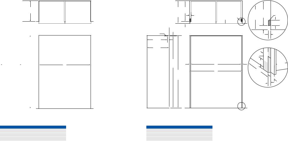
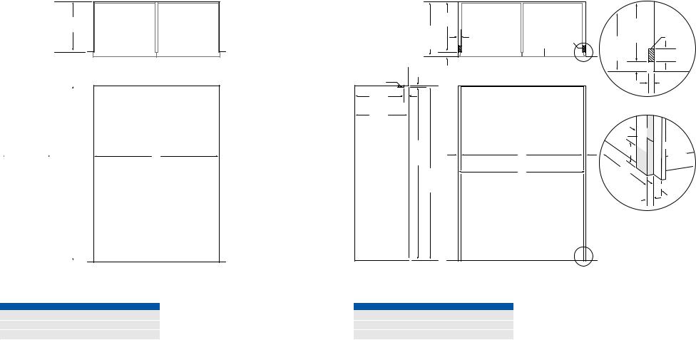
Opening Dimensions
DUAL STANDARD INSTALLATION
TOP VIEW
610 mm
OPENING
DEPTH
|
|
|
|
|
|
|
|
|
|
|
|
610 mm |
|
|
|
|
|
|
|
|
|
|
|
|
|
2127 mm |
|
||
|
|
|
|
||||||
|
OPENING DEPTH |
|
|
|
OPENING |
|
|||
|
|
|
|
|
|
|
HEIGHT |
|
|
|
|
|
|
|
|
|
|
|
|
|
|
|
|
|
|
|
|
|
|
|
|
|
|
|
|
|
|
|
|
SIDE VIEW
A |
OPENING WIDTH |
FRONT VIEW
Opening Dimensions |
|
|
|
|
|
|
|
DUAL FLUSH INSET INSTALLATION |
|
|
|
|
|
|
|
|
|
TOP VIEW |
|
|
|
|
|
665 |
610 mm |
|
|
|
|
|
|
mm |
DEPTH |
|
|
|
665 |
610 mm |
TOP VIEW |
FLUSH |
TO CLEAT |
|
|
|
mm |
OPENING |
|
INSET |
|
32 mm |
|
|
FLUSH |
DEPTH |
CLEAT |
DEPTH |
|
|
|
||||
|
TWO UNITS WITH |
CLEAT |
INSET |
TO CLEAT |
|||
|
|
|
|
||||
|
|
|
19 mm PANEL |
|
DEPTH |
|
|
|
|
|
|
|
|
|
76 mm |
|
|
|
DETAIL A |
|
|
typical |
|
|
|
|
|
|
|
||
|
56 mm |
|
|
|
|
56 mm |
|
6 mm |
|
|
|
|
|
|
|
|
|
|
|
|
|
|
|
CLEAT |
|
|
|
|
|
|
32 mm |
|
|
|
|
|
|
|
|
610 mm |
|
|
|
|
Detail A |
|
|
DEPTH TO CLEAT |
|
|
|
|
|
|
|
56 |
|
|
|
|
|
|
|
mm |
|
|
|
|
|
|
|
665 mm |
|
|
|
|
|
|
|
FLUSH INSET DEPTH |
|
|
|
|
|
|
|
|
|
|
|
|
|
76 mm |
|
|
|
|
|
|
CLEAT |
typical |
|
|
|
|
|
|
|
|
|
2127 |
|
|
|
|
|
102 |
SHADED |
|
|
|
|
|
AREA |
||
mm |
|
|
A |
|
|
mm |
MUST BE |
HEIGHT |
|
|
|
|
|
||
TO CLEAT |
32 |
|
WIDTH TO CLEAT |
|
32 |
|
FINISHED |
|
mm |
|
|
|
mm |
|
|
2134 |
|
|
B |
|
610 mm |
|
|
|
|
|
OPENING |
|
|||
mm |
|
|
FLUSH INSET WIDTH |
|
|
||
|
|
|
DEPTH TO |
|
|||
FLUSH |
|
|
|
|
|
||
|
|
|
|
CLEAT |
|
|
|
INSET |
|
|
|
|
|
56 mm |
|
|
|
|
|
|
|
||
HEIGHT |
|
|
|
|
|
|
|
|
|
|
|
|
|
|
|
|
|
|
|
|
|
32 mm |
|
|
|
|
|
|
Detail B |
|
|
|
|
|
DETAIL B |
|
|
|
|
SIDE VIEW |
FRONT VIEW |
OPENING WIDTH |
A |
A dual installation kit will be required for this installation. |
OPENING WIDTH |
A |
B |
Two 762 mm Models |
1518 mm |
|
Two 762 mm Models |
1518 mm |
1581 mm |
762 mm and 914 mm Models |
1670 mm |
|
762 mm and 914 mm Models |
1670 mm |
1734 mm |
Two 914 mm Models |
1822 mm |
|
Two 914 mm Models |
1822 mm |
1886 mm |
Dimensions assume a 19 mm panel thickness. A dual installation kit will be required for this installation.
4 | English
SITE PREPARATION
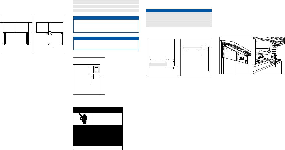
Dual Installation
If two units are installed side by side, a dual installation kit may be required. Installations without a custom filler strip require a dual installation kit. If a dual installation kit is not specified, a 51 mm filler strip is recommended between units. Dual installations without a filler strip can only be accomplished using two units with opposite hinges. Refer to the illustrations below.
Dual installation kits are available through an authorized Sub-Zero dealer. For questions regarding the installation, contact your authorized Sub-Zero dealer.
WITHOUT FILLER STRIP |
FILLER STRIP |
Opposite hinges. |
Same side hinges. |
Electrical
Installation must comply with all applicable electrical codes.
The electrical supply should be located within the shaded area shown in the illustration below. A separate circuit, servicing only this appliance is required. A ground fault circuit interrupter (GFCI) is not recommended and may cause interruption of operation.
ELECTRICAL REQUIREMENTS |
|
Power Supply |
220-240 V AC, 50/60 Hz |
Circuit Breaker |
10 amp |
Receptacle |
grounding-type (earthed) |
 CAUTION
The outlet must be checked by a qualified electrician to be sure that it is wired with the correct polarity. Verify that the outlet is properly grounded (earthed).
 WARNING
Do not use an extension cord, two-prong adapter or remove the power cord ground prong.
FRONT VIEW
178 |
E |
|
mm |
||
|
||
|
152 |
|
|
mm |
|
1918 mm |
|
|
FROM |
|
|
FLOOR |
|
Electrical supply location.
Plumbing
Installation must comply with all applicable plumbing codes.
The water supply line should be located within the shaded area shown in the illustrations below. The water supply line should be connected to the house supply with an easily accessible shut-off valve. Do not use self piercing valves. The water supply line must not interfere with installation of the anti-tip brackets.
This appliance should be connected to a potable water supply.
PLUMBING REQUIREMENTS
Water Supply Line 1/4" OD copper, braided stainless steel or PEX tubing
Water Pressure |
2.4–8.3 bar |
Excess Water Line for Connection |
.9 m |
457 mm |
152 |
|
mm |
|
76 mm |
FLOOR |
|
FRONT VIEW |
|
|
13 mm |
BACK WALL |
|
457 mm |
152 |
|
mm |
TOP VIEW |
|
Water supply location (rear). |
Water supply location (bottom). |
Preparation
Uncrate the unit and inspect for damage. Remove the wood base and discard shipping bolts and brackets. Remove and recycle packing materials. Do not discard the kickplate, antitip brackets and hardware.
Completely retract the front leveling legs to allow the unit to be moved into position. The front and rear leveling legs can be adjusted from the front once the unit is in position.
Remove the drain pan from the base of the unit to avoid damage, and allow for proper appliance dolly placement.
The grille assembly should be removed prior to moving the unit. To remove, pull out on the bottom edge of the grille and rotate upward. Loosen the back two grille mounting screws and remove the front two grille mounting screws. Refer to the illustrations below. With the grille held firmly, pull forward to remove.
BACK GRILLE |
SCREW |
FRONT |
GRILLE SCREW |
Grille removal. |
Grille mounting screws. |
Electrical
Shock
Hazard
Plug power cord directly into a properly grounded (earthed) outlet.
Do not defeat the grounding (earthing) nature of the plug.
Do not use adapter or extension cord.
Failure to follow these instructions could cause serious injury or death.
See installation instructions
subzero.com | 5

SITE PREPARATION
Anti-Tip Bracket
 WARNING
To prevent the unit from tipping forward and provide a stable installation, the unit must be secured in place with the anti-tip brackets.
The two anti-tip brackets must be installed exactly 610 mm from the front of the opening to the back of the brackets and a minimum of 102 mm from the sides of the opening. This depth will increase to 665 mm for a flush inset installation based on 19 mm thick panels. Failure to properly position the anti-tip brackets will prevent proper engagement.
Use all anti-tip bracket hardware as instructed for wood or concrete floors.
IMPORTANT NOTE: For wood or concrete floor applications, if the #12 screws do not hit a wall stud or wall plate, use the #8 screws and #12 washers with the wall anchors.
IMPORTANT NOTE: In some installations the subflooring or finished floor may necessitate angling the screws used to fasten the anti-tip brackets to the back wall.
ANTI-TIP HARDWARE
2 Anti-tip brackets
12 #12 x 64 mm pan head screws
4 3/8"–16 x 95 mm wedge anchors
12 #12 flat washers
4 #8–18 x 32 mm truss head screws
4
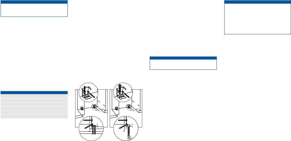
WOOD FLOOR APPLICATION
After properly locating the anti-tip brackets in the opening, drill pilot holes 5 mm diameter maximum in the wall studs or wall plate. Use the #12 screws and washers to secure the brackets. Verify the screws penetrate through the flooring material and into wall studs or wall plate a minimum of 19 mm. Refer to the illustration below.
CONCRETE FLOOR APPLICATION
After properly locating the anti-tip brackets in the opening, drill pilot holes 5 mm diameter maximum in the wall studs or wall plate. Drill 10 mm diameter holes into the concrete a minimum of 38 mm deep. Use the #12 screws and washers to secure the brackets to the wall, and use the 3/8" wedge anchors to secure the brackets to the floor. Verify the screws penetrate wall studs or wall plate a minimum of 19 mm. Refer to the illustration below.
CONCRETE WEDGE ANCHOR INSTALLATION:
1Drill a 10 mm diameter hole any depth exceeding the minimum embedment. Clean the hole or drill additional depth to accommodate drill fines.
2Assemble the washer and nut flush with the end of anchor to protect threads. Drive the anchor through the material to be fastened until the washer is flush with the surface material.
3Expand the anchor by tightening the nut 3–5 turns past hand-tight position or to 34 newton-meters of torque.
 WARNING
Verify there are no electrical wires or plumbing in the area which the screws could penetrate.
610 |
mm |
102 mm |
MIN |
FINISHED |
FLOORING |
WALL PLATE
SUBFLOORING
WOOD FLOOR
|
610 |
|
|
mm |
|
|
102 mm |
|
|
MIN |
|
|
FINISHED |
|
|
FLOORING |
|
WALL PLATE |
|
|
SUBFLOORING |
|
|
CONCRETE |
38 mm |
|
MIN |
||
FLOOR |
||
|
Wood floor. |
Concrete floor. |
 CAUTION
Always wear safety glasses and use other necessary protective devices or apparel when installing or working with anchors.
Anchors are not recommended for use in lightweight masonry material such as block or brick, or for use in new concrete which has not had sufficient time to cure. The use of core drills is not recommended to drill holes for the anchors.
6 | English

INSTALLATION |
PANEL INSTALLATION |
Placement
 CAUTION
Before moving the unit into position, secure door(s) closed and protect any finished flooring.
Use an appliance dolly to move the unit near the opening.
If the unit has been on its back or side, it must stand upright for a minimum of 24 hours before connecting power.
Plug the power cord into the grounded outlet and roll the unit into position. Verify the anti-tip brackets are properly engaged.
IMPORTANT NOTE: If used, side panels will need to be installed before the unit is placed in its final position. Refer to page 8.
Water Line
Approximately .9 m of 1/4" plastic tubing is connected to the unit with a preassembled 1/4" compression connection under the unit. The water line fitting connection kit, provided with the unit, contains a 1/4" compression union fitting for connection to the household water line.
Purge the water line prior to final connection to the unit. This will remove any debris that may be present in the tubing from installing the new water line.
Place the sleeve and nut on the water line and fasten to the connection at the end of the tubing. Do not over tighten. Check all water line fittings for leaks. Verify the
drain pan can be installed and removed without water line interference.
IMPORTANT NOTE: If a reverse osmosis system used, it is recommended that the water filtration system be bypassed by removing the filter.
IMPORTANT NOTE: Water lines can not be exposed to freezing temperatures.
Custom Panels
For overlay and flush inset applications, custom door and grille panels must be installed. Panel size is critical for a proper fit. To verify panel requirements and dimensions, refer to the Sub-Zero design guide at subzero.com/specs.
IMPORTANT NOTE: Flush inset applications require a minimum 13 mm reveal on all sides.
Finish all sides of custom panels. They may be visible when the door is open.
EXTERNAL DISPENSER
For external dispenser models, the dispenser glasswell will need to be removed before custom panels can be installed.
IMPORTANT NOTE: The total panel thickness (including backer and spacer, if used) in the glasswell area can range from 6 mm to a maximum 29 mm. If the panel is thicker, the area must be routed to 29 mm maximum thickness.
To remove the glasswell, lift the water grille up and out. Remove the control panel by removing the center plastic mandrel supports. Tilt the control panel out and disconnect the wire harness (blue side up) from the back side. Remove the bezel by removing the four screws. Refer to the illustrations below.
Once custom panels have been installed, reverse the procedure to reinstall the glasswell.
ICE
WATER
LOCK
INDICATOR LIGHT
WATER
GRILLE
Dispenser glasswell. |
Glasswell removal. |
subzero.com | 7
PANEL INSTALLATION
Custom Panels
DOOR PANELS
To install custom door panels, remove the handle side trim molding. Insert a screwdriver tip into the top corner slot on the handle side and pop out the trim. For the drawer,
insert a screwdriver tip into the slot on either side of the trim running along the top of the drawer and pop out the trim. Remove the screws and frame. Refer to the illustrations below.
The door has a 6 mm frame for the custom panel to slide into. If the panel is thicker than a 6 mm, rout an edge around the panel or mount the panel on a sheet of 6 mm thick material, then insert into the frame.
A 3 mm space is required between the backer panel and the custom panel to allow the panel to slide into the door frame. Refer to the illustrations below for critical dimensions.
Install handle hardware before inserting the panel. Large D-style handles are recommend rather than knobs. Screw heads must be countersunk into the panel.
Slide the panel into the frame.
To reinstall the door trim molding, insert the top of the trim into grooves at the top of the door and work downward, snapping the trim into clips on the door frame. For the drawer, start at one end and move towards the opposite end, snapping the trim into the clips.
SPACER PANEL |
CUSTOM PANEL |
BACKER PANEL |
TRIM |
8 mm min |
3 mm (OVERLAY) |
CUSTOM |
SPACER |
|
PANEL |
|
PANEL |
|
|
BACKER |
|
|
PANEL |
19 |
|
|
mm |
3 |
6 |
typical |
mm |
mm |
Door side trim. |
Drawer top trim. |
Panel assembly cross section |
Panel assembly rear view. |
|
|
(overlay). |
|
GRILLE PANEL
Remove the bottom grille frame by extracting the lower two corner screws from each side of the grille assembly. Refer to the illustration below.
With the bottom section removed, slide the custom grille panel into the frame. If the panel is thinner than 6 mm, a filler material will need to be installed to achieve a proper fit. Once the panel is installed, reattach the bottom grille frame by sliding the corner brackets back into position, then reinstall the four corner screws.
BOTTOM |
GRILLE |
FRAME |
Grille frame assembly.
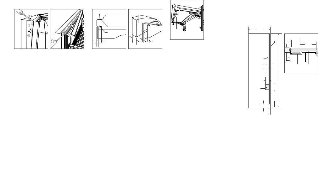
SIDE PANEL
When installing a custom side panel, an accessory kit is required and is available through an authorized Sub-Zero dealer. Stainless steel and white enamel side panels are also available from an authorized Sub-Zero dealer.
IMPORTANT NOTE: The use of side panels may change the width of the opening.
A custom side panel must be a minimum of 610 mm deep and 13 mm thick. Routing will be necessary for the side panel to fit flush against the side of the unit. Refer to the illustrations below.
IMPORTANT NOTE: The height of the side panel will vary with the height of the grille. Verify the finished height before modifying panels.
IMPORTANT NOTE: For over-and-under and French door models, additional routing will be necessary to accommodate the lower hinge plate of the refrigerator.
610 mm |
|
|
|
|
FRONT |
|
|
|
OF SIDE |
|
|
|
PANEL |
25 mm |
|
|
|
|
|
|
|
|
48 mm |
ROUT TO 3 mm |
|
3 mm |
|
|
13 mm |
|
|
|
|
|
|
48 mm |
|
MAIN |
SIDE PANEL |
|
|
||
25 mm |
2134 |
FRAME |
ROUTING |
|
mm |
|
|
Routing detail.
108 mm |
|
|
|
|
|
|
|
|
|
|
|
|
|||
|
|
|
|
|
|
|
|
|
|
|
|
|
|
|
|
ROUT TO |
146 |
||||||
5 mm |
mm |
||||||
(OVER-AND-UNDER |
|
|
|
||||
MODELS) |
|
|
|
||||
|
|
|
|
|
|
|
|
521 mm
102 mm
OPTIONAL
TOE KICK 
 67 mm CUT-OUT
Side panel dimensions.
8 | English

INSTALLATION
Alignment
LEVELING
Once the unit is in position, turn the front leveling legs clockwise to adjust the height. The rear height adjustment can be made from the front of the roller base. Using a 3/8" socket, turn the 3/8" hex bolt clockwise to raise the unit or counterclockwise to lower. Use the lowest torque setting when using a power drill. Do not turn the rear leveling legs by hand. Refer to the illustration below.
When the unit is properly leveled, door and drawer adjustments are less likely to be necessary.
IMPORTANT NOTE: Level the unit to the floor, not surrounding cabinetry. This could affect the operation of the unit, such as door closing.
 WARNING
To reduce the possibility of the unit tipping forward, the front leveling legs must be in contact with the floor.
FRONT
LEVELING LEG
REAR
ADJUSTMENT
Rear roller base adjustment.
DOOR ADJUSTMENT
The doors of side-by-side and over-and-under models can be adjusted in and out, and side to side tilt. The doors of side-by-side models can also be adjusted up and down.
To make adjustments, slightly loosening the two upper hinge bolts on the upper hinge plate using a 1/2" wrench. Refer to the illustration below.
In and out adjustment | For a left-hinge door, using a 5/32" allen wrench, turn the adjustment bolt clockwise to bring the handle side of the door inward, and counterclockwise to move the handle side outward. Reverse directions for a right-hinge door.
Side to side tilt adjustment | For a left-hinge door, using a
3/8" wrench, turn the adjustment bolt clockwise to raise the handle side of the door, and counterclockwise to lower the handle side. Reverse directions for a right-hinge door.
Up and down adjustment | For a left-hinge door, using a 1/4" allen wrench, turn the adjustment bolt clockwise to raise the door and counterclockwise to lower. Refer to the illustration below. Reverse directions for a right-hinge door.
UPPER
HINGE BOLTS
IN AND OUT
ADJUSTMENT
SIDE TO SIDE
TILT ADJUSTMENT
Door adjustment bolts. |
Up and down door adjustment. |
Completion
GRILLE INSTALLATION
Install the grille assembly and check for proper fit. The grille is designed to rest on the upper door hinge(s) to minimize the reveal between the top of the door and bottom of the grille. To eliminate interference, the grille height can be adjusted. Loosen the four grille adjustment screws (two on each side) and adjust the grille height as needed. Refer to the illustration below.
BACK GRILLE |
SCREW |
GRILLE |
ADJUSTMENT |
SCREW |
FRONT |
GRILLE SCREW |
Grille height adjustment.
ANCHORING
After the unit has been leveled and door adjustment completed, anchor the unit to the opening to ensure a proper fit and secure installation.
To anchor the top of the unit, open the grille and install the screws provided, through the grille frame into cabinetry. There are several hole locations. Refer to the illustration below. Check for proper door clearance by opening the door.
To anchor the bottom of the unit, drive a screw through the side hole inside each roller base assembly. The screw will need to go in at an angle to attach properly. Refer to the illustration below. Additional material may be needed behind the cleat to ensure sufficient anchoring.
 CAUTION
If the screws provided are not suitable for the installation, use adequate screws.
ANCHORING
SCREWS
ANCHORING
SCREW
Top anchoring. |
Bottom anchoring. |
subzero.com | 9

INSTALLATION
Completion
Reinstall the drain pan and verify it is in the proper position.
Install the kickplate using screws to attach it to brackets on the inside of each roller base. Refer to the illustration below. The kickplate must be removable for service. The floor cannot interfere with removal. Refer to the label mounted on the kickplate support for height clearance.
Turn power on by touching  on the control panel.
Install the light diffuser by aligning the slots of the light diffuser onto the bracket pegs and pulling forward so the tabs on the slots engage the bracket pegs. Refer to the illustration below.
|
PEG |
|
SLOT |
Kickplate installation. |
Light diffuser installation. |
90° DOOR STOP
The doors of all models open to 110°. A 90° door stop is provided with the unit (located behind the grille). Additional 90° door stop kits are available through an authorized Sub-Zero dealer.
 WARNING
Follow all city and state laws when storing, recycling or discarding unused refrigerators and freezers.
10 | English
Sub-Zero, Sub-Zero & Design, Dual Refrigeration, Constant Care, The Living Kitchen, Great American Kitchens The Fine Art of Kitchen Design, and Ingredients are registered trademarks and service marks of Sub-Zero, Inc. Wolf, Wolf & Design, Wolf Gourmet, W & Design and the color red as applied to knobs are registered trademarks and service marks of Wolf Appliance, Inc. (collectively, the “Company Marks.”) All other trademarks or registered trademarks are property of their respective owners in the United States and other countries.
subzero.com | 11
REFRIGERACIÓN EMPOTRABLE
Índice
2Refrigeración empotrable
3Medidas de la cavidad
5 Instalación doble
5 Potencia
5 Fontanería
5Preparación
6Soporte antivuelco
7Colocación
7 Toma de agua
7 Paneles a medida
9 Alineación
9 Comprobación
Nota importante:
Para garantizar que este producto se instala y funciona de la forma más eficaz y segura posible, tenga en cuenta la información que se destaca en esta guía:
Cuando aparece NOTA IMPORTANTE, se resalta información que resulta especialmente importante.
PRECAUCIÓN indica una situación en la que se pueden sufrir heridas leves o provocar daños al producto si no se siguen las instrucciones.
AVISO indica peligro de que se produzcan heridas personales graves o incluso la muerte si no se siguen las precauciones especificadas.
Información sobre el producto
En la placa de datos del producto encontrará información importante sobre este, incluyendo el modelo y el número de serie de la unidad. La placa de datos del producto está situada en el marco superior de la unidad, dentro de la puerta. Consulte la siguiente ilustración.
Si necesita recurrir a un servicio técnico, póngase en contacto con su distribuidor de Sub-Zero autorizado.
PLACA
DE DATOS
Ubicación de la placa de datos.
Herramientas y materiales
•Destornilladores: estándar y Phillips.
•Taladro.
•Brocas (se necesitarán brocas de mampostería para una instalación determinada).
•Tornillos de cabeza Torx: T-10, 15 y 20.
•Juego de llaves Allen estándar.
•Juego de llaves y llaves de vaso estándar.
•Niveles de 0,6 m y 1,2 m.
•Instrumento especial para cortar el tubo.
•Tubo de 0,9 m de 1/4" de cobre OD, acero inoxidable trenzado o de PEX.
•Válvula de montaje.
•Material para proteger la casa, el suelo y los armarios de cocina durante la instalación.
2 | Español
PREPARACIÓN DEL SITIO
Medidas de la cavidad
INSTALACIÓN ESTÁNDAR
VISTA SUPERIOR
610 mm
PROFUNDIDAD DE LA CAVIDAD
|
|
|
|
|
|
|
|
|
|
|
610 mm |
|
|
|
|
|
|
|
|
|
|
|
2.127 mm |
|||
|
|
|
||||||
|
PROFUNDIDAD |
|
|
ALTURA DE |
||||
|
DE LA CAVIDAD |
|
|
LA CAVIDAD |
||||
|
|
|
|
|
|
|
|
|
|
|
|
|
|
|
|
|
|
|
|
|
|
|
|
|
|
|
VISTA LATERAL
A |
ANCHURA DE LA CAVIDAD |
VISTA FRONTAL
Medidas de la cavidad |
|
|
|
|
|
|
|
|
|
INSTALACIÓN EMPOTRABLE |
|
|
|
|
|
|
|
|
|
|
|
|
VISTA SUPERIOR |
|
|
|
|
||
|
610 mm |
|
|
|
|
|
|
|
|
|
PROF. HASTA |
|
|
|
|
|
610 mm |
|
|
|
EL LISTÓN |
|
|
|
|
|
PROF. DE |
VISTA SUPERIOR |
|
|
665 mm |
|
|
|
|
|
|
LA CAVIDAD |
|
|
PROFUNDIDAD |
|
32 mm |
|
LISTÓN |
|
665 |
HASTA |
LISTÓN |
|
DE INSTALACIÓN |
|
|
|
|
EL LISTÓN |
|
||
|
EMPOTRABLE |
|
|
UNIDAD CON |
|
|
mm |
|
|
|
|
|
PANEL DE 19 mm |
|
|
PROFUNDIDAD |
76 mm |
||
|
|
|
|
|
|
|
DE INSTALACIÓN |
||
|
|
|
|
DETALLE A |
|
EMPOTRABLE |
estándar |
||
|
|
|
|
|
|
|
|
||
|
56 mm |
|
|
|
|
|
56 mm |
|
|
|
|
|
|
|
|
|
|
||
|
6 mm |
|
|
|
|
|
|
|
|
LISTÓN |
|
|
|
|
|
|
|
|
32 mm |
|
|
|
|
|
|
|
|
|
|
610 mm |
|
|
|
|
|
|
Detalle A |
|
|
PROF. HASTA |
56 |
|
|
|
|
|
|
|
|
EL LISTÓN |
|
|
|
|
|
|
|
|
|
|
mm |
|
|
|
|
|
|
|
|
665 mm |
|
|
|
|
|
|
|
|
|
PROFUNDIDAD |
|
|
|
|
|
|
|
|
|
DE INSTALACIÓN |
|
|
|
|
|
|
|
76 mm |
|
EMPOTRABLE |
|
|
|
|
|
|
|
|
|
|
|
|
|
|
|
|
LISTÓN |
estándar |
|
|
|
|
|
|
|
|
|
|
|
|
2.127 |
|
|
|
|
|
|
102 |
ES NECESARIO |
|
|
|
|
|
|
|
FINALIZAR |
||
|
mm |
|
|
A |
|
|
|
mm |
LA ZONA |
|
ALTURA |
|
|
|
|
|
|
||
|
32 |
|
|
32 |
|
|
SOMBREADA |
||
|
HASTA EL |
ANCH. HASTA EL LISTÓN |
|
|
|||||
|
|
|
|
||||||
|
LISTÓN |
mm |
|
|
|
mm |
610 mm |
|
|
|
2.134 |
|
|
B |
|
|
|
||
|
|
|
|
|
PROF. DE |
|
|||
|
mm |
|
|
ANCHURA DE |
|
|
LA CAVIDAD |
|
|
|
ALTURA DE |
|
INSTALACIÓN EMPOTRABLE |
|
HASTA EL LISTÓN |
56 mm |
|||
|
INSTALACIÓN |
|
|
|
|
|
|
|
|
|
EMPOTRABLE |
|
|
|
|
|
|
|
|
|
|
|
|
|
|
|
|
32 mm |
|
|
|
|
|
|
|
|
Detalle B |
|
|
|
|
|
|
DETALLE B |
|
|
|
|
|
VISTA LATERAL |
VISTA FRONTAL |
ANCHURA DE LA CAVIDAD |
A |
Modelo de 762 mm |
746 mm |
Modelo de 914 mm |
902 mm |
Modelo de 1.067 mm |
1.054 mm |
Modelo de 1.219 mm |
1.206 mm |
Si va a instalar dos unidades una junto a la otra, consulte la página 4.
ANCHURA DE LA CAVIDAD |
A |
B |
Modelo de 762 mm |
746 mm |
813 mm |
Modelo de 914 mm |
902 mm |
965 mm |
Modelo de 1.067 mm |
1.054 mm |
1.118 mm |
Modelo de 1.219 mm |
1.206 mm |
1.270 mm |
Las medidas están calculadas con un panel de 19 mm de grosor. Si va a instalar dos unidades una junto a la otra, consulte la página 4.
subzero.com | 3
PREPARACIÓN DEL SITIO
Medidas de la cavidad
INSTALACIÓN DOBLE ESTÁNDAR
VISTA SUPERIOR
610 mm
PROFUNDIDAD DE LA CAVIDAD
|
|
|
|
|
|
|
|
|
|
|
|
610 mm |
|
|
|
|
|
|
|
|
|
|
|
|
|
2.127 mm |
|
||
|
|
|
|
||||||
|
PROFUNDIDAD |
|
|
|
ALTURA DE |
|
|||
|
DE LA CAVIDAD |
|
|
|
LA CAVIDAD |
|
|||
|
|
|
|
|
|
|
|
|
|
|
|
|
|
|
|
|
|
|
|
|
|
|
|
|
|
|
|
|
|
VISTA LATERAL
A |
ANCHURA DE LA CAVIDAD |
VISTA FRONTAL
Medidas de la cavidad |
|
|
|
|
|
|
|
INSTALACIÓN DOBLE EMPOTRABLE |
|
|
|
|
|
|
|
|
|
VISTA SUPERIOR |
|
|
|
|
|
610 mm |
|
|
|
|
|
|
|
PROF. HASTA |
|
|
|
|
610 mm |
|
|
EL LISTÓN |
|
|
|
|
PROF. DE |
VISTA SUPERIOR |
|
665 |
|
|
|
|
|
||
|
|
|
|
LA CAVIDAD |
|
||
mm |
|
|
|
|
|
||
PROFUNDIDAD |
|
32 mm |
2 UNIDADES CON |
LISTÓN |
665 |
HASTA |
LISTÓN |
DE INSTALACIÓN |
|
|
EL LISTÓN |
|
|||
|
|
PANEL DE 19 mm |
|
mm |
|
|
|
EMPOTRABLE |
|
|
|
PROFUNDIDAD |
|
||
|
|
|
|
|
|||
|
|
|
|
|
76 mm |
||
|
|
|
|
|
DE INSTALACIÓN |
||
|
|
|
DETALLE A |
EMPOTRABLE |
estándar |
||
|
|
|
|
|
|
||
56 mm |
|
|
|
|
56 mm |
|
|
|
|
|
|
|
|
||
6 mm |
|
|
|
|
|
|
|
LISTÓN |
|
|
|
|
|
|
32 mm |
|
|
|
|
|
|
|
|
610 mm |
|
|
|
|
Detalle A |
|
|
PROF. HASTA EL LISTÓN |
|
|
|
|
|
|
|
56 |
|
|
|
|
|
|
|
mm |
|
|
|
|
|
|
|
665 mm |
|
|
|
|
|
|
|
PROFUNDIDAD DE |
|
|
|
|
|
|
|
INSTALACIÓN |
|
|
|
|
|
|
|
EMPOTRABLE |
|
|
|
|
|
76 mm |
|
|
|
|
|
|
LISTÓN |
estándar |
|
|
|
|
|
|
|
|
|
2.127 |
|
|
|
|
|
|
ES NECESARIO |
mm |
|
|
|
|
|
102 |
|
|
|
|
|
|
FINALIZAR |
||
ALTURA |
|
|
|
|
|
||
|
|
A |
|
|
mm |
LA ZONA |
|
HASTA |
32 |
|
|
32 |
|
||
|
ANCH. HASTA EL LISTÓN |
|
|
SOMBREADA |
|||
EL LISTÓN |
|
|
|
||||
mm |
|
|
|
mm |
|
|
|
|
|
|
|
|
|
||
2.134 |
|
|
B |
|
610 mm |
|
|
|
|
|
PROF. DE |
|
|||
mm |
|
|
ANCHURA DE INSTALACIÓN EMPOTRABLE |
|
|
||
|
|
|
LA CAVIDAD |
|
|||
ALTURA DE |
|
|
|
|
|
||
|
|
|
|
HASTA EL LISTÓN |
|
||
INSTALACIÓN |
|
|
|
|
56 mm |
||
|
|
|
|
|
|
||
EMPOTRABLE |
|
|
|
|
|
|
|
|
|
|
|
|
|
32 mm |
|
|
|
|
|
|
Detalle B |
|
|
|
|
|
DETALLE B |
|
|
|
|
VISTA LATERAL |
VISTA FRONTAL |
ANCHURA DE LA CAVIDAD |
A |
Para esta instalación se necesita un kit de instalación doble. |
ANCHURA DE LA CAVIDAD |
A |
B |
Dos modelos de 762 mm |
1.518 mm |
|
Dos modelos de 762 mm |
1.518 mm |
1.581 mm |
Modelos de 762 mm y 914 mm |
1.670 mm |
|
Modelos de 762 mm y 914 mm |
1.670 mm |
1.734 mm |
Dos modelos de 914 mm |
1.822 mm |
|
Dos modelos de 914 mm |
1.822 mm |
1.886 mm |
Las medidas están calculadas con un panel de 19 mm de grosor. Para esta instalación se necesita un kit de instalación doble.
4 | Español

PREPARACIÓN DEL SITIO
Instalación doble
Si va a instalar dos unidades una junto a la otra, puede que sea necesario un kit de instalación doble. Asimismo, las instalaciones que no utilicen un embellecedor a medida necesitarán un kit de instalación doble. Si no se especifica el kit de instalación doble, se recomienda utilizar un embellecedor de 51 mm entre las unidades. Las instalaciones dobles sin embellecedor solamente se pueden llevar a cabo con dos unidades con las bisagras opuestas. Observe las siguientes ilustraciones.
Podrá encontrar los kits de instalación doble en un distribuidor de Sub-Zero autorizado. Si tiene dudas relacionadas con la instalación, póngase en contacto con su distribuidor de Sub-Zero autorizado.
SIN EMBELLECEDOR |
EMBELLECEDOR |
Bisagras opuestas. |
Bisagras al mismo lado. |
Potencia
La instalación debe cumplir con toda la normativa local aplicable en materia de electricidad.
La toma eléctrica debe situarse en el área sombreada en la siguiente ilustración. Se necesita un circuito independiente para esta unidad. No se recomienda utilizar un interruptor de circuito de fallos de toma de tierra (GFCI), ya que puede interrumpir el funcionamiento de la unidad.
REQUISITOS ELÉCTRICOS |
|
Alimentación eléctrica |
220-240 V CA, 50/60 Hz |
Magnetotérmico |
10 amperios |
Enchufe |
con toma de tierra |
 PRECAUCIÓN
La toma de corriente debe ser revisada por un electricista cualificado para comprobar que la conexión se ha realizado con la polaridad correcta. Compruebe que la toma de corriente está conectada a tierra de manera correcta.
 AVISO
AVISO
No utilice alargadores ni adaptadores, ni quite la clavija de toma a tierra del cable eléctrico.
VISTA FRONTAL
178 |
E |
|
mm |
||
|
||
|
152 |
|
|
mm |
|
1.918 mm |
|
|
DESDE |
|
|
EL SUELO |
|
|
Ubicación de la alimentación |
||
eléctrica. |
|
|
Potencia Descarga eléctrica
Enchufe el cable eléctrico directamente en una toma con conexión a tierra.
No manipule la conexión a tierra del enchufe. No utilice adaptadores ni alargadores.
Si no sigue estas instrucciones, existe riesgo de que se produzcan heridas graves o incluso la muerte.
Ver instrucciones de instalación
Fontanería
La instalación debe cumplir con toda la normativa local aplicable en materia de fontanería.
La toma de agua puede situarse en el área sombreada de las siguientes ilustraciones. El conducto de abastecimiento de agua se debe conectar al suministro de la casa con una válvula de cierre de fácil acceso. No utilice conexiones
auto perforantes. El conducto del agua no debe interferir en la instalación de los soportes antivuelco.
Este aparato se debe conectar a una toma de agua potable.
REQUISITOS DE FONTANERÍA |
|
Conducto de abastecimiento de |
Tubo de 1/4" de cobre OD, |
agua |
acero inoxidable trenzado o |
|
de PEX |
Presión del agua |
2,4–8,3 bares |
Conducto de agua sobrante para |
0,9 m |
conexión |
|
457 mm |
152 |
|
mm |
|
76 mm |
MADERA |
|
VISTA FRONTAL |
|
Ubicación de la toma de agua (trasera).
|
13 mm |
PARED TRASERA |
|
457 mm |
152 |
|
mm |
VISTA SUPERIOR |
|
Ubicación de la toma de agua (superior).
Preparación
Desembale la unidad y compruebe si tiene algún daño o desperfecto. Retire la base de madera y extraiga todos los tornillos y soportes del paquete. Quite y recicle los materiales de embalaje. No tire el zócalo, los soportes antivuelco ni las piezas de montaje.
Repliegue completamente las patas de nivelación delanteras para permitir que la unidad se pueda colocar en la posición adecuada. Las patas de nivelación delanteras y traseras pueden ajustarse desde la parte delantera cuando la unidad ya esté colocada.
Retire el depósito de desagüe de la base de la unidad para evitar que se dañe y para que se pueda colocar bien la plataforma rodante.
Retire la rejilla antes de mover la unidad. Para ello, tire del borde inferior de la rejilla e incline el marco de la rejilla hasta sacarlo hacia arriba. Afloje los dos tornillos traseros de montaje de la rejilla y retire los dos tornillos de montaje delanteros. Observe las siguientes ilustraciones. Sujete firmemente la rejilla y tire hacia adelante para extraerla.
TORNILLO TRASERO |
DE LA REJILLA |
TORNILLO |
DELANTERO |
DE LA REJILLA |
Extracción de la rejilla. |
Tornillos de montaje de la rejilla. |
subzero.com | 5
PREPARACIÓN DEL SITIO
Soporte antivuelco
 AVISO
AVISO
Para impedir que la unidad se incline hacia adelante y conseguir que su colocación sea estable, es necesario sujetar la unidad con los soportes antivuelcos.
Los dos soportes antivuelco se deben instalar exactamente a 610 mm de la parte delantera de la cavidad hasta la parte
trasera de los soportes y con un mínimo de 102 mm desde los lados de la cavidad. Esta profundidad se incrementará hasta 665 mm si se trata de una instalación empotrable con paneles delgados de 19 mm. Si no coloca bien los soportes antivuelcos, es posible que los soportes no queden bien fijados.
Utilice todas las piezas del soporte antivuelco tal y como se indica en las instrucciones para suelos de madera o de hormigón.
NOTA IMPORTANTE: para aplicaciones en madera o en un suelo determinado, en caso de que los tornillos del n.º 12 no alcancen el montante o la placa de pared, utilice tornillos del n.º 8 y arandelas del n.º 12 con los anclajes para pared.
NOTA IMPORTANTE: en algunas instalaciones es posible que, debido al tipo de suelo o acabado de este, sea necesario colocar los tornillos inclinados para sujetar los soportes antivuelco a la pared trasera.
PIEZAS ANTIVUELCO
2 Soportes antivuelco
12 Tornillos de cabeza plana del n.º 12 (64 mm)
4 Anclajes de expansión de 16 x 95 mm – 3/8"
12 Arandelas planas del n.º 12
4 Tornillos de cabeza ovalada de del n.° 8 (18 x 32 mm)
4 Anclajes para pared de nailon Zip-it®
APLICACIÓN EN SUELO DE MADERA
Tras colocar correctamente los soportes antivuelco en la cavidad, perfore orificios guía de 5 mm de diámetro como máximo en los montantes de pared o en la placa de pared. Utilice arandelas y tornillos del n.º 12 para fijar los soportes. Compruebe que los tornillos penetren en el material del suelo y en los montantes de pared o en las placas un mínimo de 19 mm. Consulte la siguiente ilustración.
APLICACIÓN EN SUELO DE HORMIGÓN
Tras colocar correctamente los soportes antivuelco en la cavidad, perfore orificios guía de 5 mm de diámetro como máximo en los montantes de pared o en la placa de pared. Realice orificios de 10 mm de diámetro en el hormigón con una profundidad mínima de 38 mm. Utilice arandelas y tornillos del n.º 12 para fijar los soportes a la pared, y anclajes de expansión de 3/8" para fijar los soportes al suelo. Compruebe que los tornillos penetran en los montantes de pared o en las placas un mínimo de 19 mm. Consulte la siguiente ilustración.
INSTALACIÓN DE ANCLAJES DE EXPANSIÓN PARA HORMIGÓN:
1Haga un agujero de 10 mm de diámetro con una profundidad superior al incrustado mínimo. Limpie el orificio o continúe taladrando para hacer que el orificio sea más profundo y quepan en él los residuos.
2Coloque la arandela y la tuerca al nivel del extremo del anclaje para proteger las roscas. Inserte el anclaje en el material en el que debe atornillarse hasta que la arandela quede nivelada con el material de la superficie.
3Extienda el anclaje mediante una llave que sirva para apretar la tuerca de 3 a 5 vueltas más de su posición lograda con el apriete manual o hasta 34 newtons metros de par.
 AVISO
AVISO
Compruebe que no haya cables eléctricos ni tuberías en el área en la que se van a introducir los tornillos.
610 |
mm |
102 mm |
MIN |
O |
CABADO |
PLACA |
DE PARED |
TIPO DE SUELO
SUELO DE MADERA
|
610 |
|
mm |
|
102 mm |
|
MIN |
|
O |
|
CABADO |
PLACA |
|
DE PARED |
|
TIPO DE SUELO |
|
SUELO DE |
38 mm |
HORMIGÓN |
MIN |
Suelo de madera. |
Suelo de hormigón. |
 PRECAUCIÓN
Lleve siempre gafas de seguridad y utilice cualquier otro dispositivo o ropa de protección que sea necesario cuando esté instalando o trabajando con anclajes.
Se recomienda no utilizar los anclajes en material de mampostería poco pesado, por ejemplo, bloques o ladrillos, ni utilizarlo en hormigón fresco que no se haya secado el tiempo suficiente. No se recomienda utilizar brocas huecas para hacer orificios para los anclajes.
6 | Español
 Loading...