

Page 1

Studer Innotec SA 2013 V1.0.5
51X
Xcom-GSM / Xcom-LAN
Remote communication sets
for Xtender and VarioTrack systems
User Manual
Page 2

Studer Innotec SA
Xcom-GSM/Xcom-LAN
2 V1.0.5 User manual
Page 3

Studer Innotec SA
Xcom-GSM/Xcom-LAN
User Manual V1.0.5 3
CONTENTS
1
INTRODUCTION ...................................................................................................................................... 5
1.1 Remote communication set for Xtender and VarioTrack systems ............................................. 5
1.2 Conventions .......................................................................................................................................... 5
1.3 Warranty and liability .......................................................................................................................... 5
1.3.1 Warranty and liability ...................................................................................................................... 5
1.3.2 Exclusion of warranty ...................................................................................................................... 6
1.3.3 Exclusion of liability .......................................................................................................................... 6
1.3.4 Compatibility .................................................................................................................................... 6
1.4 Safety precautions ............................................................................................................................... 6
1.4.1 Generalities ....................................................................................................................................... 6
1.4.2 Warnings ............................................................................................................................................ 6
2 MOUNTING AND IN ST AL LATION ........................................................................................................... 7
2.1 Installation of the Xcom 232i .............................................................................................................. 7
3 WIRING ................................................................................................................................................... 7
3.1 Xcom-GSM set ...................................................................................................................................... 7
3.1.1 Contents of the remote communication set Xcom-GSM ....................................................... 8
3.1.2 Mounting place ............................................................................................................................... 8
3.1.3 Installing the SIM card .................................................................................................................... 8
3.1.4 Connecting the GSM modem ...................................................................................................... 8
3.2 Xcom-LAN set ....................................................................................................................................... 9
3.2.1 Contents of the remote communication set Xcom-LAN ........................................................ 9
3.2.2 Mounting place ............................................................................................................................... 9
3.2.3 Connecting the Ethernet gateway ............................................................................................. 9
4 CONFIGURING THE XCOM-232I ......................................................................................................... 10
4.1 Download the software .................................................................................................................... 10
4.2 Insert the SD card ............................................................................................................................... 10
4.3 Select the SD card drive ................................................................................................................... 10
4.4 Set the parameters ............................................................................................................................ 11
4.4.1 For Xcom-LAN ................................................................................................................................ 11
4.4.2 For Xcom-GSM ............................................................................................................................... 11
4.5 Generate the configuration file ...................................................................................................... 12
4.6 Remove the SD card ......................................................................................................................... 13
4.7 Setup the parameters in the Xcom-232i ........................................................................................ 13
4.8 Creation of your account ................................................................................................................ 14
4.9 Registration of installation ................................................................................................................ 15
4.10 Installation completed ...................................................................................................................... 16
5 XCOM PORTAL ..................................................................................................................................... 16
5.1 Home Page ......................................................................................................................................... 16
5.2 Facility Page........................................................................................................................................ 16
5.2.1 Installation ....................................................................................................................................... 16
5.2.2 Remote Control ............................................................................................................................. 16
5.2.3 Sharing ............................................................................................................................................. 16
5.2.4 Messages ........................................................................................................................................ 16
5.2.5 Notifications .................................................................................................................................... 16
6 NOTES ................................................................................................................................................... 17
Page 4

Studer Innotec SA
Xcom-GSM/Xcom-LAN
4 V1.0.5 User manual
Page 5
Studer Innotec SA
Xcom-GSM/Xcom-LAN
User Manual V1.0.5 5
1 INTRODUCTION
1.1 REMOTE COMMUNICATION SET FOR XTENDER AND VARIOTRACK SYSTEMS
The remote communication sets Xcom-LAN or Xcom-GSM allow you to view, configure
and control Xtender and VarioTrack systems from anywhere in the world. With a simple
Internet access on a Smartphone, a tablet or a notebook, your installation is accessible
through a virtual remote control on Studer’s dedicated web portal. This virtual remote
control’s interface is designed to resemble the standard remote control RCC-02/-03 and
offers the same functionality as if on-site. By keeping the same interface as the RCC-02/03,
managing the system is easy and f am iliar.
All information and warning messages are listed on the server and can be used as a
trigger to send messages by E-mail or SMS. Access to the web portal can easily be giv en
to a third part if assistance is needed to analyse or configure a system.
Two solutions are provided to access the virtual remote control:
Xcom-LAN, for systems connected to a wired Local Area Network giving access to the
internet WEB
Xcom-GSM, for systems with no available LAN but access to the GSM network, either by
GPRS (worldwide) or by 3G (WCDMA).
The present manual is valid for both the Xcom-LAN and Xcom-GSM remote
communication sets. Before installation of the communication system, carefully read this
user manu al and proceed thereafter with the installation and configuration as explained
in the following chapters.
For further information on the d iffer en t devi ces of these sets, ple ase r efer to th e res pec tive
user manuals.
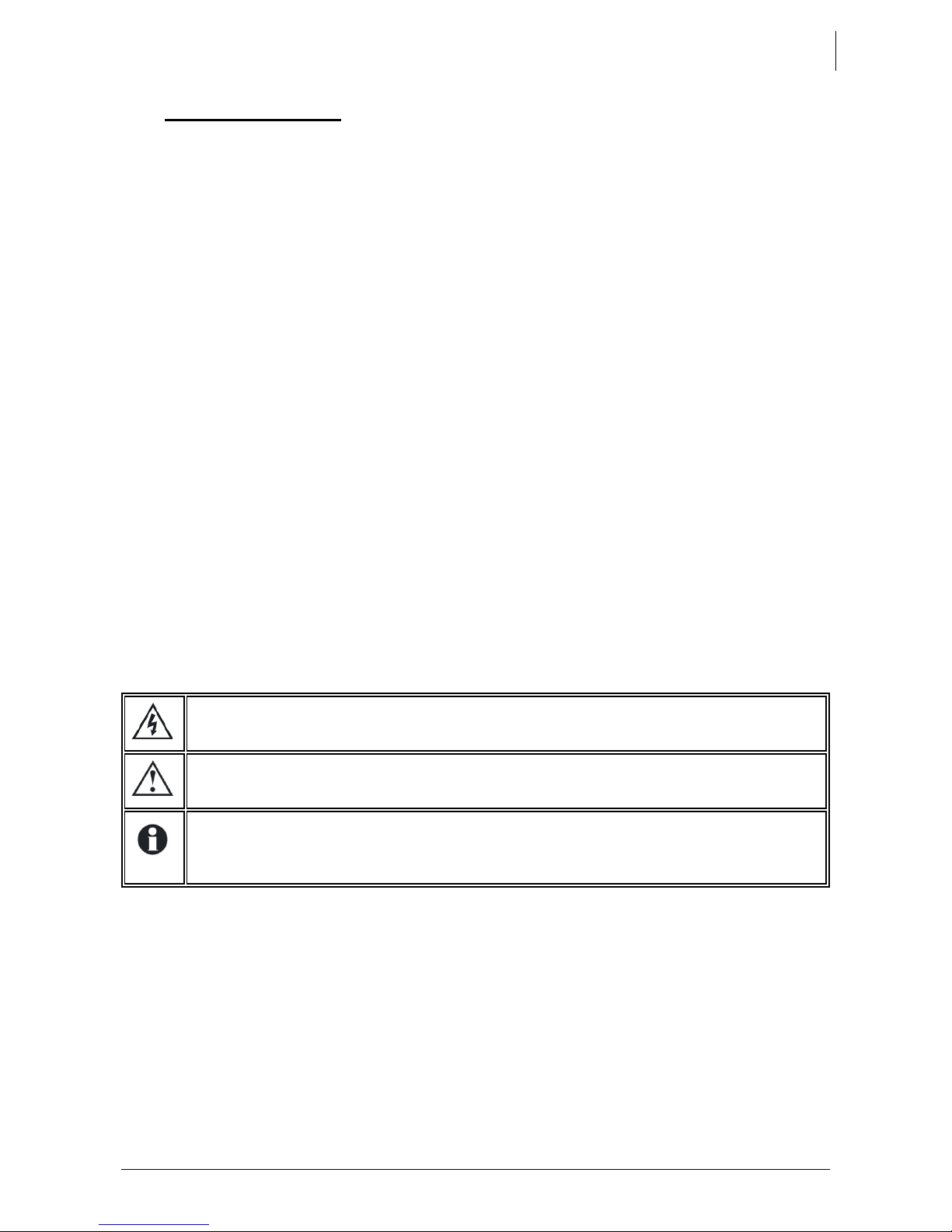
1.2 CONVENTIONS
This symbol is used to indicate the presence of a dangerous voltage that is
sufficient to constitute a risk of electric shock.
This symbol is used to indicate a risk of material damage and/or the cancellation
of the guarantee.
This symbol is used to indicate a procedure or function that is important for a safe
and correct use of the equipment
. Failure to respect these instructions may lead
to the cancellation of t he gu arantee or to a non-compliant installation.
1.3 WARRANTY AND LIABILITY
1.3.1 Warranty and liability
During production and assembly, each Xcom-232i undergoes several controls and tests
which strictly comply with established procedures. Each Xcom-232i is given a serial
number all o w ing a perfect f o llow-up of the controls, in conformity with the specific data of
every device. For this reason, it is very important to nev er remove the descriptiv e sticker
bearing the serial number. The production, assembling and tests of each Xcom-232i are
entirely carried out in our factory in Sion (CH). The warranty for this pr oduct depends on
the strict application of the instructions in this manual.
Page 6

Studer Innotec SA
Xcom-GSM/Xcom-LAN
6 V1.0.5 User manual
1.3.2 Exclusion of warranty
No warranty claims will be accepted for damages caused by handling, operation or
actions that are not described in this manual. Damages arisen from the following events
are excluded from the warranty:
• Overvoltage on the device.
• Liquid in the device or oxidation due to condensation.
• Damage resulting from a fall or a mechanical shock.
• Modifications carried out without the explicit authorization of Studer Innotec SA.
• Nuts or screws partially or insuff iciently tightened during installation or maintenance.
• Damage due to atmospheric overvoltage (lightning).
• Damage due to inappropriate transport or packaging.
• Disappearance of original ide ntification m arks.
1.3.3 Exclusion of liability
Installation, commissioning, use and maintenance of this device cannot be supervised by
Studer Innotec SA. For this reason, we do not accept any liability for damage, costs or
losses resulting from an ins tallation that does not comply with the instructions, by a faulty
operation or by inadequate maintenance. The use of this device is under the responsibility
of the end-user. This device is neither designed nor guaranteed for the supply of life
support applications or any other critical application with potential risks for human beings
or for the environment. We shall assume no liability for patent infringement or other third
party rights involved in the use of this device.
1.3.4 Compatibility
Studer Innotec SA guarantees the compatibility of the software updates with the
hardware for one year, starting from the date of purchase. The updates are no longer
guaranteed beyond this date and a hardware upgrade ma y be req uire d. Ple ase contac t
your reseller for any additional information on compatibility.
1.4 SAFETY PRECAUTIONS
1.4.1 Generalities
Do read carefully all safety instructions before proceeding to the installation and
commissioning of the device. Not respecting these instructions might constitute a lethal
physical danger but can also damage the functionalities o f t h e device. Therefore do keep
this manual close to the de vic e.
Do, for any in s tallation, follow strictly t h e local and national norms and regulations in force.
1.4.2 Warnings
• The installation and commissioning of the communication sets must be entrusted to
skilled and qualified personnel perfectly aware of the safety precautions and local rules
in force.
• All components connected to this device must be conforming to the laws and
regulations in force. The persons without a written authorization from Studer Innotec SA
are forbidden to do any change, modification or repair whatsoever. Regarding
authorized modifications and replacements, only genuine components shall be used.
• This device is meant for indoor use only and must under no circumstances stand in the
rain, the snow or any other humid or dusty environment.
• In case of use in motor vehicles this device must also be protected against vibrations by
absorbing components.
Page 7

Studer Innotec SA
Xcom-GSM/Xcom-LAN
User Manual V1.0.5 7
2 MOUNTING AND INSTALLATION
Both the Xcom-GSM and the Xcom-LAN are powered through the Studer proprietary bus.
The distance between the Xco m-232i and the devic e supplying it (Xtender or VarioTrack)
should not exceed 10m in ord er to avoid excessive voltage drop in the wire whic h could
affect the functionality.
2.1 INSTALLATION OF THE XCOM 232I
Follow the Xcom-232i instruction manual.
When the Xcom-232i has been installed correctly according to the procedures mentioned
in its manual, the remaining installation procedure depends on the chosen remote
communication set.
3 WIRING
3.1 XCOM-GSM SET
In order to install the Xcom-GSM set, there need to be sufficient GSM network coverage
on the site of the Xtender or VarioTrack system. The network also has to conform to one of
the following standards: GSM / GPRS / EDGE / UMTS / HSDPA on these frequencies 850 /
900/ 1800 / 1900 / 2100 MHz.
The GSM modem “E-lins M400” supplied by Studer Innotec requi res the in stal la tion of a SIM
card (not provided) that allows data transfer from a local service provider. Please refer to
the chap. 3.1.3 when installing the SIM card.
The volume of data transferring via the communication system to Studer’s server will
depend on its utilisation (frequency and duration of use) but it will necessitate at least 2MB
data per month. When the remote communication is in use, the volume of data
transferred is approximately 30kB per minute. When the data logger function is activated,
the additional volume of daily data may represent up to 1MB per day, depending on the
number of devices present on the Studer communication bus.
If a Xc om-232i is connected to another compatible device (Xtender, VarioTrack,
BSP, RCC) with the same communication bus, it is highly recommended to make
a software update in ord er to guarantee all functionalities o f t h e system.
Configuration of the Xcom-232i will be carried out after the installation of the
selected gateway (GSM or LAN) in accordance with chapter 4.
The system will not function properly with any other modems than the ones stated
above, even if they are correctly connected to the Xcom -232i.
Page 8

Studer Innotec SA
Xcom-GSM/Xcom-LAN
8 V1.0.5 User manual
3.1.1 Contents of the remote communication set Xcom-GSM
The remote communication set Xcom-GSM is delivered with the material listed below:
• 1 Xcom-232i
• 2m communication cable
• 1 MicroSD with adaptor
• 1 M400 cellular modem
• 1 external antenna
• 0.25m serial cable
• 0.5m power supply cable RJ45-Jack
• 1 Xcom-232i user manual
• 1 M400 series cellular modem datasheet
• 1 Xcom-GSM/Xcom-LAN user manual
3.1.2 Mounting place
The GSM modem should be mounted close to the Xc om-232i, maximu m 20cm apart, and
fixed with two separate sliding pins into the rail of the GSM enclosure.
3.1.3 Installing the SIM card
Eject the small drawer close to the antenna connector by pushing the yellow button n ext
to it, place the SIM card in the slot and re insert the drawer.
3.1.4 Connecting the GSM modem
1) Connect the antenna to t h e m o dem
2) Connect the serial cable bet w een the modem and the Xcom-232i
3) Connect the power cable bet ween the modem and the Xcom -232i
4) Connect the Studer communication cable between the Xcom-232i and the
installation
The termination switch next to the 2 RJ 45 connectors on the Xcom-232i
must be
set in position T.
Page 9

Studer Innotec SA
Xcom-GSM/Xcom-LAN
User Manual V1.0.5 9
3.2 XCOM-LAN SET
3.2.1 Contents of the remote communication set Xcom-LAN
The remote communication set Xcom-LAN is delivered with the material listed below.
• 1 Xcom-232i
• 2m communication cable
• 1 MicroSD with adaptor
• 1 NPort 5110A Ethernet gateway
• 3m Ethernet cable
• 0.25m serial cable
• 0.5m power supply cable RJ45-Jack
• 1 NPort 5110A series quick installation guide
• 1 Xcom-GSM/Xcom-LAN user manual
3.2.2 Mounting place
The Ethernet gateway should be mounted on a smooth surface using the mounting holes
as shown in the "NPort 5110A series quick installation guide".
3.2.3 Connecting the Ethernet gateway
1) Connect the Ethernet cable between th e E t hern et gateway and the router
2) Connect the serial cable bet w een the Ethernet gateway and the Xcom-232i
3) Connect the power cable bet ween the Ethernet gateway and the Xcom-232i
4) Connect the Studer communication cable between the Xcom-232i and the
Xtender or Va rio T rack installation
The termination switch next to the 2 RJ 45 connectors on the Xcom-
232i must be
set in position T.
Page 10

Studer Innotec SA
Xcom-GSM/Xcom-LAN
10 V1.0.5 User manual
4 CONFIGURING THE XCOM-232I
For the installation to function properly, the Xcom-232i must first be configured as shown,
step-by-step, in this chapt er.
The use of a RCC-02/03 will facilitate the installation of the Xcom-
232i. It will show
messages in case of error.
4.1 DOWNLOAD THE SOFTWARE
Go on the Studer Innotec website:
http://www.studer-innotec.com
-> Support -> Download Center -> Softwares and U pdates
Download the package "Xcom Configurator".
4.2 INSERT THE SD CARD
Insert the SD card into yo ur P C an d run t he "XCOM Configurator".
4.3 SELECT THE SD CARD DRIVE
Choose the drive where th e SD card is situated.
Figure 4.2 : Choose the drive
Figure 4.1 : Studer Innotec SA website
Choose the SD card drive
Page 11

Studer Innotec SA
Xcom-GSM/Xcom-LAN
User Manual V1.0.5 11
4.4 SET THE PARAMETERS
4.4.1 For Xcom-LAN
To use the Xcom-232i with the Ethernet gateway, choose ”LAN” as serial port mode. No
others parameters are required. The gateway is already confi gured. Press “Generate” to
save the parameter sett ings.
Figure 4.3 : Choose Ethernet mode
4.4.2 For Xcom-GSM
To use the Xcom-232i with the GSM modem, choose “Modem” as serial port mode.
Then enter the "Access Point Name" (APN ) of the internet service provider (ISP). If the ISP
requires a username and a password, use them to fill in the fields "Access Point User Name"
and "Access Point Password". If no password is required, leave the fields blank.
If the SIM card has a PI N code, use it to fill in the field "PIN Code". If there is no PIN code,
put a “0” in the field. Press “Generate” to save the par am eter settings.
Figure 4.4 : Choose Modem mode
Ask the Internet Service Provider.
Required for some Internet Service
Providers, leave it blank if not.
Enter the SIM card PIN code
if there is one
Choose GSM mode
Choose LAN mode
Generate the configuration file
Generate the configuration file
Page 12

Studer Innotec SA
Xcom-GSM/Xcom-LAN
12 V1.0.5 User manual
Example for Swisscom in Switzerland:
Figure 4.5 : Example with parameters for Swisscom
4.5 GENERATE THE CONFIGURATION FILE
If the parameters were suc cessfully set, this message box wil l appear:
Figure 4.6 : Parameters set and successful generation of GUID
Close the message box and a text file with your GUID will appear . This file is saved on your
Desktop.
KEEP IT SAFE! The GUID is required for your authentication on the Xcom Website.
Figure 4.7 : Generated GUID file
Page 13

Studer Innotec SA
Xcom-GSM/Xcom-LAN
User Manual V1.0.5 13
If an error occurs during the GUID generation, this message box will appear. Please v erify
that the selected drive for the SD card is correct. If an adaptor is used for the SD card,
please verify that there is no lock protection.
Figure 4.8 : SD card not found
4.6 REMOVE THE SD CARD
Remove the SD card from th e P C.
4.7 SETUP THE PARAMETERS IN THE XCOM-232I
Insert the SD card into the Xcom-232i
and wait for the update to finish. The
updating process normally takes 1
second. When the LED stops blinking
red, the update is finished.
Figure 4.9 : Inserting the SD card
Page 14

Studer Innotec SA
Xcom-GSM/Xcom-LAN
14 V1.0.5 User manual
4.8 CREATION OF YOUR ACCOUNT
To access the installation remotely, the web portal https://xcom.studer-innotec.com is
provided free of charge.
To set up a user account on this web portal, please follow the instructions below. If a user
account already exists , plea se proceed to chapter “4.9 Reg ist ra tio n o f insta l lat io n” .
On the first page, click on the link "Create an account".
Figure 4.10 : Link "Create an account"
1. Enter your last name, first name, emai l address and the password of your choice.
4.11 : Insert account information
2. Click on the button « Save », to register your information and your user account will
be created.
Page 15

Studer Innotec SA
Xcom-GSM/Xcom-LAN
User Manual V1.0.5 15
4.9 REGISTRATION OF INSTALLATION
In order to access the installation you need to enter the GUID previously generated for
your installation, see chapter 4.5.
1. Click on the button "Add a new installa tion".
4.12 : "Add a new installation" button
2. Enter the previously generated GUID as well as the name of the installation and
press register to save the information.
4.13 : Register a new installation
Enter the installation GUID
Enter the installation name
Press the"Register" button to save the installation
Page 16

Studer Innotec SA
Xcom-GSM/Xcom-LAN
16 V1.0.5 User manual
4.10 INSTALLAT ION COMPLETED
The installation is now completed and you can access your system from anywhere with
internet access throug h St uder’s web portal https://xcom.studer-innotec.com
5 XCOM PORTAL
The user interface has been conceived to be simple and intuitive.
5.1 HOME PAGE
The home page lists all available installations to the logged-in user divided into two
categories.
• My installations; the installations that the logged-in user has added to the system.
• My shared installations; the installations to which the logged-in user has been granted
access.
Find a specific installation by scrolling the list or by using the search-field. Access the
facility page by pressing the "Manage" button. An installation can also be deleted by
pressing the "Delet e" button. The delete button is only available for the installations under
"My installations".
5.2 FACILITY PAGE
This page is divided into five tabs whose functions are described below:
5.2.1 Installation
This tab contains a detailed description of the facility, including its featured components,
specific settings or other information to indicate its expected behaviour, in order to easily
identify the system.
5.2.2 Remote Control
This tab allows direct access to the facility. The interface is identical to the remote control
RCC-02/-03 and access to the system will be exactly the same as if you used a RCC-02/03.
Due to variations in communication speed, a greater or lesser delay may appear and
prompt the user to wait fo r the return cal l display befo re making the next command. It is
also possible that the screen refresh is done in two refreshments, slowing all navigation
procedures. This respo n se variable is normal and will requir e som e practice.
5.2.3 Sharing
This tab allows you to give access to your installation to additional persons registered at
the Xcom portal (it is possible for everyone to register to the Xcom portal). The access can
be set to partial or full access.
5.2.4 Messages
This tab shows all messages from the Xcom-232i. These messages reflect the historical
performance of your installation and are not necessarily alarms or alerts.
5.2.5 Notifications
This tab allows you to generat e alerts via SMS or email depending o n co nf i gurable criteria.
Generation of S MS alert s requir es the pr ovision o f SMS cre dit from a su pplier of this ty pe of
service (e.g. Clickatell, Esendex, Sms Factor, Text Magic).
Page 17

Studer Innotec SA
Xcom-GSM/Xcom-LAN
User Manual V1.0.5 17
6 NOTES
________________________________________________________________________________________________
________________________________________________________________________________________________
________________________________________________________________________________________________
________________________________________________________________________________________________
________________________________________________________________________________________________
________________________________________________________________________________________________
________________________________________________________________________________________________
________________________________________________________________________________________________
________________________________________________________________________________________________
________________________________________________________________________________________________
________________________________________________________________________________________________
________________________________________________________________________________________________
________________________________________________________________________________________________
________________________________________________________________________________________________
________________________________________________________________________________________________
________________________________________________________________________________________________
________________________________________________________________________________________________
________________________________________________________________________________________________
________________________________________________________________________________________________
________________________________________________________________________________________________
________________________________________________________________________________________________
________________________________________________________________________________________________
________________________________________________________________________________________________
________________________________________________________________________________________________
________________________________________________________________________________________________
________________________________________________________________________________________________
________________________________________________________________________________________________
________________________________________________________________________________________________
________________________________________________________________________________________________
________________________________________________________________________________________________
________________________________________________________________________________________________
________________________________________________________________________________________________
________________________________________________________________________________________________
________________________________________________________________________________________________
________________________________________________________________________________________________
________________________________________________________________________________________________
________________________________________________________________________________________________
________________________________________________________________________________________________
Page 18

Studer Innotec SA
Xcom-GSM/Xcom-LAN
18 V1.0.5 User manual
________________________________________________________________________________________________
________________________________________________________________________________________________
________________________________________________________________________________________________
________________________________________________________________________________________________
________________________________________________________________________________________________
________________________________________________________________________________________________
________________________________________________________________________________________________
________________________________________________________________________________________________
________________________________________________________________________________________________
________________________________________________________________________________________________
________________________________________________________________________________________________
________________________________________________________________________________________________
________________________________________________________________________________________________
________________________________________________________________________________________________
________________________________________________________________________________________________
________________________________________________________________________________________________
________________________________________________________________________________________________
________________________________________________________________________________________________
________________________________________________________________________________________________
________________________________________________________________________________________________
________________________________________________________________________________________________
________________________________________________________________________________________________
________________________________________________________________________________________________
________________________________________________________________________________________________
________________________________________________________________________________________________
________________________________________________________________________________________________
________________________________________________________________________________________________
________________________________________________________________________________________________
________________________________________________________________________________________________
________________________________________________________________________________________________
________________________________________________________________________________________________
________________________________________________________________________________________________
________________________________________________________________________________________________
________________________________________________________________________________________________
________________________________________________________________________________________________
________________________________________________________________________________________________
________________________________________________________________________________________________
________________________________________________________________________________________________
Page 19

Studer Innotec SA
Xcom-GSM/Xcom-LAN
User Manual V1.0.5 19
Page 20

Studer Innotec SA
Rue des Casernes 57
1950 Sion – Switzerland
Tel. : +41(0) 27 205 60 80
Fax : +41(0) 27 205 60 88
info@studer-innotec.com
www.studer-innotec.com
 Loading...