

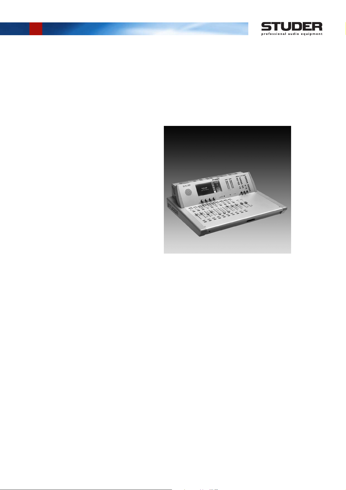
Studer OnAir 1000
Digital Mixing Console
SW Version 4.0/4.03
Operating Instructions

Prepared and edited by Copyright by Studer Professional Audio GmbH
Studer Professional Audio GmbH Printed in Switzerland
Technical Documentation Order no. 10.27.4872 (Ed. 0405)
Althardstrasse 30
CH-8105 Regensdorf – Switzerland
http://www.studer.ch Subject to change
Studer is a registered trade mark of Studer Professional Audio GmbH, Regensdorf
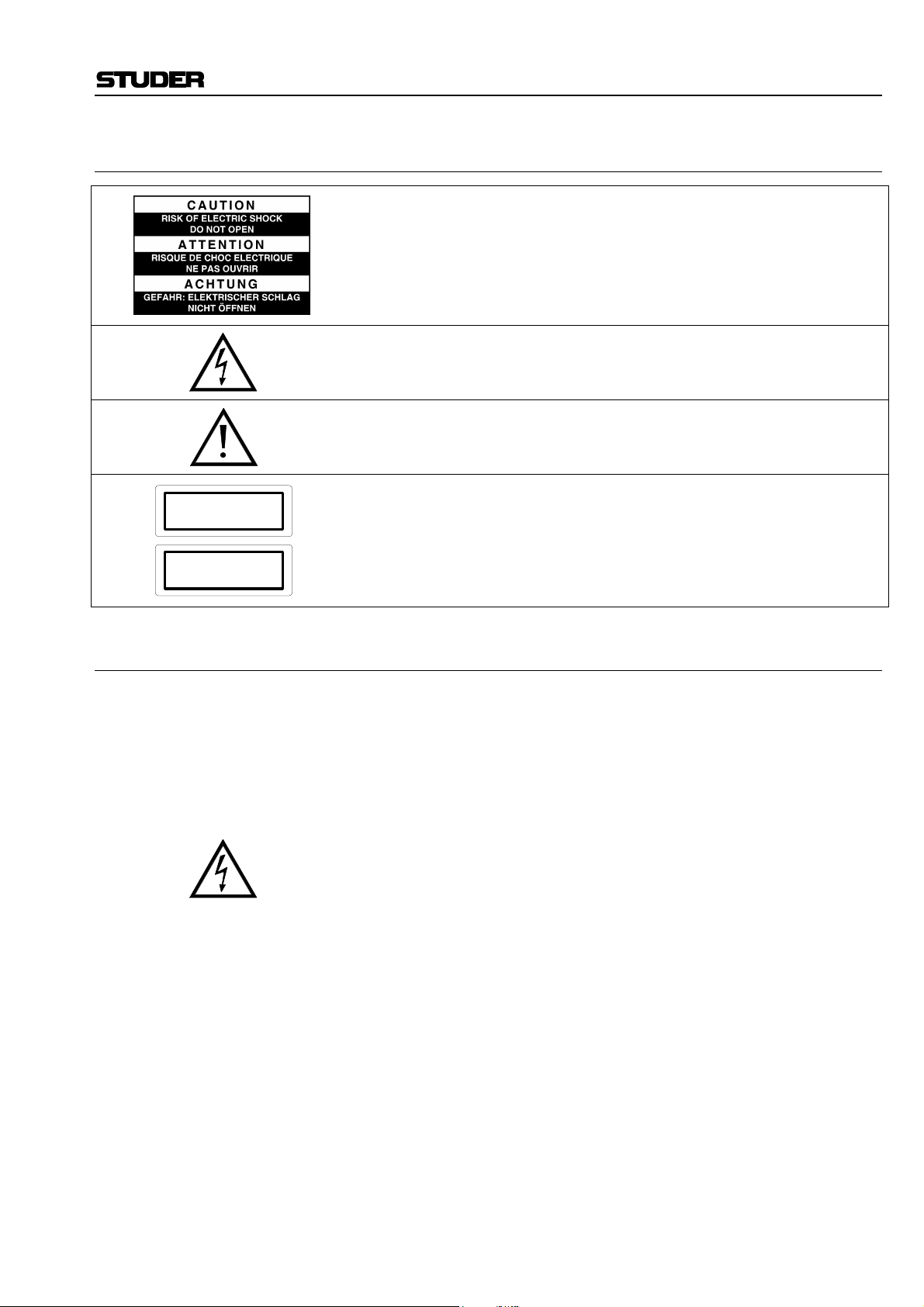
A Safety Information
To reduce the risk of electric shock, do not remove covers. No userserviceable parts inside. Refer servicing to qualified service personnel
(i.e., persons having appropriate technical training and experience necessary to be aware of hazards to which they are exposed in performing a
repair action, and of measures to minimize the danger of themselves).
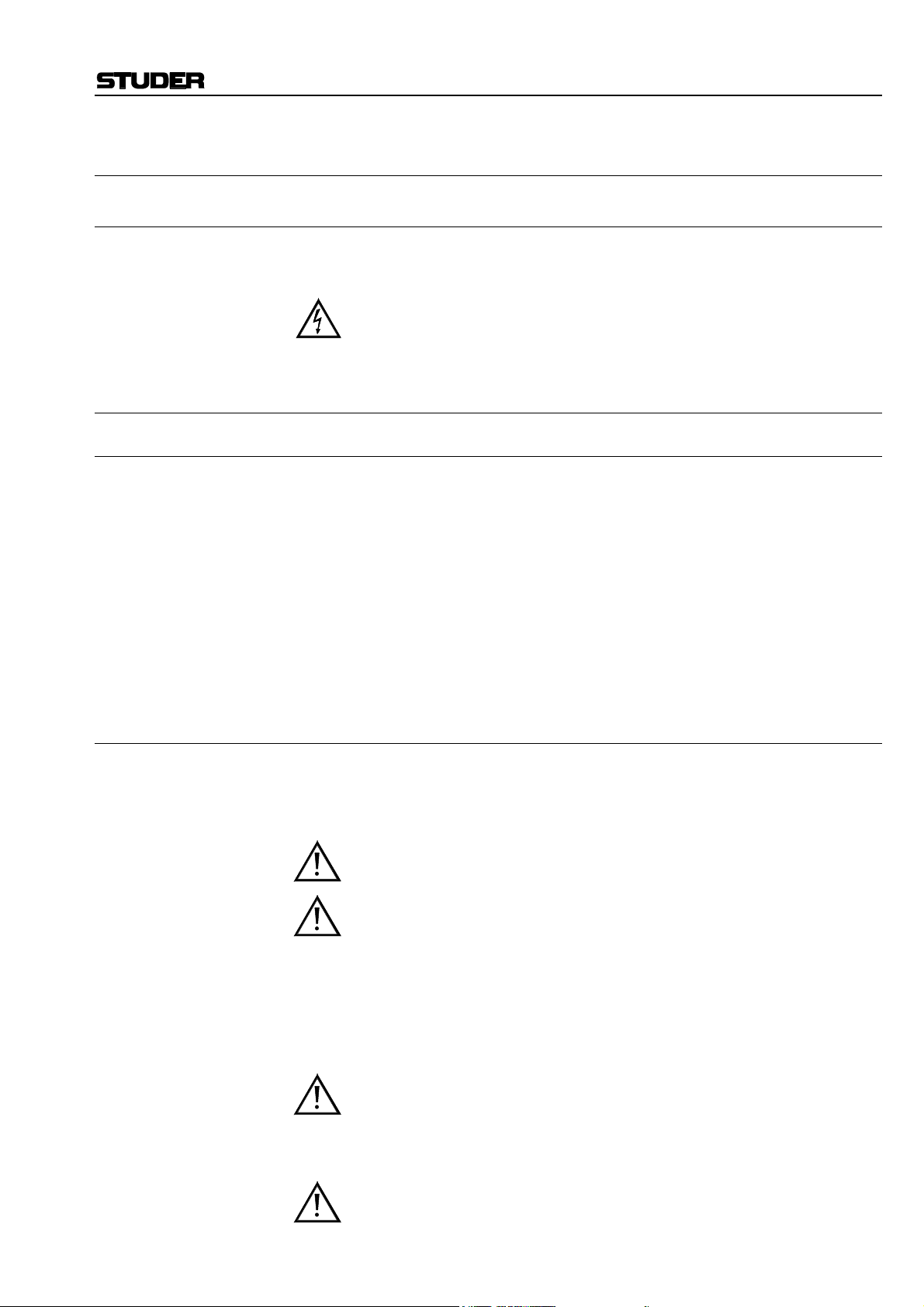
This symbol alerts the user to the presence of un-insulated dangerous
voltage within the equipment that may be of sufficient magnitude to constitute a risk of electric shock to a person.
This symbol alerts the user to important instructions for operating and
maintenance in this documentation.
Safety Information
CLASS I
LED PRODUCT
CLASS I
LASER PRODUCT
A1 First Aid
Assemblies or sub-assemblies of this product can contain opto-electronic
devices. As long as these devices comply with Class I of laser or LED
products according to EN 60825-1:1994, they will not be expressly
marked on the product. If a special design should be covered by a higher
class of this standard, the device concerned will be marked directly on
the assembly or sub-assembly in accordance with the above standard.
In Case of Electric Shock: Separate the person as quickly as possible from the electric power
source:
• By switching off the equipment,
• By unplugging or disconnecting the mains cable, or
• By pushing the person away from the power source, using dry,
insulating material (such as wood or plastic).
• After having suffered an electric shock, always consult a doctor.
Warning! Do not touch the person or his clothing before the power is turned
off, otherwise you stand the risk of suffering an electric shock as
well!
If the Person is Unconscious: • Lay the person down
• Turn him to one side
• Check the pulse
• Reanimate the person if respiration is poor
• Call for a doctor immediately.
I

Installation/Maintenance/ESD
B General Installation Instructions
Please consider besides these general instructions also any product-specific
instructions in the “Installation” chapter of this manual.
B1 Unpacking
Check the equipment for any transport damage. If the unit is mechanically
damaged, if liquids have been spilled or if objects have fallen into the unit,
it must not be connected to the AC power outlet, or it must be immediately
disconnected by unplugging the power cable. Repair must only be per-
formed by trained personnel in accordance with the applicable regulations.
B2 Installation Site
Install the unit in a place where the following conditions are met:
• The temperature and the relative humidity of the environment must be
within the specified limits during operation of the unit. Relevant values
are the ones at the air inlets of the unit.
• Condensation must be avoided. If the unit is installed in a location with
large variation of ambient temperature (e.g. in an OB-van), appropriate
precautions must be taken before and after operation (for details on this
subject, refer to Appendix 1).
• Unobstructed air flow is essential for proper operation. Air vents of the
unit are a functional part of the design and must not be blocked in any
way during operation (e.g. by objects placed upon them, placement of
the unit on a soft surface, or installation of the unit within a rack or
piece of furniture).
• The unit must not be heated up by external sources of heat radiation
(sunlight, spot lights).
B3 Earthing and Power Supply
Earthing of units with mains supply (class I equipment) is performed via
the protective earth (PE) conductor integrated in the mains cable. Units
with battery operation (< 60 V, class III equipment) must be earthed separately.
Earthing the unit is one of the measures for protection against electrical
shock hazard (dangerous body currents). Hazardous voltage may not only
be caused by a defective power supply insulation, but may also be introduced by the connected audio or control cables.
If the unit is installed with one or several external connections, its earthing
must be provided during operation as well as while the unit is not operated.
If the earthing connection can be interrupted, for example, by unplugging
the mains plug of an external power supply unit, an additional, permanent
earthing connection must be installed using the provided earth terminal.
Avoid ground loops (hum loops) by keeping the loop surface as small as
possible (by consequently guiding the earth conductors in a narrow, parallel way), and reduce the noise current flowing through the loop by inserting
an additional impedance (common-mode choke).
II
Class I Equipment (Mains Operation)
ESD/Repair
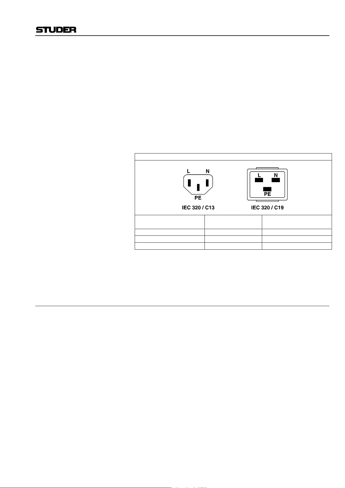
Should the equipment be delivered without a matching mains cable, the
latter has to be prepared by a trained person using the attached female plug
(IEC320/C13 or IEC320/C19) with respect to the applicable regulations in
your country.
Before connecting the equipment to the AC power outlet, check that the
local line voltage matches the equipment rating (voltage, frequency) within
the admissible tolerance. The equipment fuses must be rated in accordance
with the specifications on the equipment.
Equipment supplied with a 3-pole appliance inlet (protection conforming to
class I equipment) must be connected to a 3-pole AC power outlet so that
the equipment cabinet is connected to the protective earth.
For information on mains cable strain relief please refer to Appendix 2.
Female Plugs (IEC320), Front-Side View:
European Standard
(CENELEC)
Brown L (Live) Black
Blue N (Neutral) White
Green/Yellow PE (Protective Earth) Green (or Green/Yellow)
Class III Equipment (Battery Operation up to 60 VDC)
Equipment of this protection class must be earthed using the provided earth
terminal, if one or more external signals are connected to the unit (see explanation at the beginning of this paragraph).
B4 Electromagnetic Compatibility (EMC)
The unit conforms to the protection requirements relevant to electromagnetic phenomena that are listed in guidelines 89/336/EC and FCC, part 15.
• The electromagnetic interference generated by the unit is limited in such
a way that other equipment and systems can be operated normally.
• The unit is adequately protected against electromagnetic interference so
that it can operate properly.
The unit has been tested and conforms to the EMC standards of the specified electromagnetic environment, as listed in the following declaration.
The limits of these standards ensure protection of the environment and corresponding noise immunity of the equipment with appropriate probability.
However, a professional installation and integration within the system are
imperative prerequisites for operation without EMC problems.
For this purpose, the following measures must be followed:
• Install the equipment in accordance with the operating instructions. Use
the supplied accessories.
• In the system and in the vicinity where the equipment is installed, use
only components (systems, equipment) that also fulfill the EMC standards for the given environment.
• Use a system grounding concept that satisfies the safety requirements
(class I equipment must be connected with a protective ground conduc-
North American Standard
(NAS)
III
Installation/Maintenance/ESD
tor) and that also takes into consideration the EMC requirements. When
deciding between radial, surface, or combined grounding, the advantages and disadvantages should be carefully evaluated in each case.
• Use shielded cables where shielding is specified. The connection of the
shield to the corresponding connector terminal or housing should have a
large surface and be corrosion-proof. Please note that a cable shield
connected only single-ended can act as a transmitting or receiving antenna within the corresponding frequency range.
• Avoid ground loops or reduce their adverse effects by keeping the loop
surface as small as possible, and reduce the noise current flowing
through the loop by inserting an additional impedance (e.g. commonmode choke).
• Reduce electrostatic discharge (ESD) of persons by installing an appropriate floor covering (e.g. a carpet with permanent electrostatic filaments) and by keeping the relative humidity above 30%. Further measures (e.g. conducting floor) are usually unnecessary and only effective if
used together with corresponding personal equipment.
• When using equipment with touch-sensitive operator controls, please
take care that the surrounding building structure allows for sufficient
capacitive coupling of the operator. This coupling can be improved by
an additional, conducting surface in the operator’s area, connected to the
equipment housing (e.g. metal foil underneath the floor covering, carpet
with conductive backing).
C Maintenance
All air vents and openings for operating elements (faders, rotary knobs)
must be checked on a regular basis, and cleaned in case of dust accumulation. For cleaning, a soft paint-brush or a vacuum cleaner is recommended.
Cleaning the surfaces of the unit is performed with a soft, dry cloth or a
soft brush.
Persistent contamination can be treated with a cloth that is slightly humidified with a mild cleaning solution (soap-suds).
For cleaning display windows, commercially available computer/TV
screen cleaners are suited. Use only a slightly damp (never wet) cloth.
Never use any solvents for cleaning the exterior of the unit! Liquids must
never be sprayed or poured on directly!
For equipment-specific maintenance information please refer to the corresponding chapter in the Operating and Service Instructions manuals.
D Electrostatic Discharge during Maintenance and Repair
Caution: Observe the precautions for handling devices sensitive to electrostatic dis-
charge!
Many semiconductor components are sensitive to electrostatic discharge
(ESD). The life-span of assemblies containing such components can be
drastically reduced by improper handling during maintenance and repair
work. Please observe the following rules when handling ESD sensitive
components:
• ESD sensitive components should only be stored and transported in the
packing material specifically provided for this purpose.
• When performing a repair by replacing complete assemblies, the removed assembly must be sent back to the supplier in the same packing
IV

E Repair
ESD/Repair
material in which the replacement assembly was shipped. If this should
not be the case, any claim for a possible refund will be null and void.
• Unpacked ESD sensitive components should only be handled in ESD
protected areas (EPA, e.g. area for field service, repair or service bench)
and only be touched by persons who wear a wristlet that is connected to
the ground potential of the repair or service bench by a series resistor.
The equipment to be repaired or serviced as well as all tools and electrically semi-conducting work, storage, and floor mats should also be connected to this ground potential.
• The terminals of ESD sensitive components must not come in uncontrolled contact with electrostatically chargeable (voltage puncture) or
metallic surfaces (discharge shock hazard).
• To prevent undefined transient stress of the components and possible
damage due to inadmissible voltages or compensation currents, electrical connections should only be established or separated when the
equipment is switched off and after any capacitor charges have decayed.
Removal of housing parts, shields, etc. exposes energized parts. For this
reason the following precautions must be observed:
• Maintenance may only be performed by trained personnel in accordance
with the applicable regulations.
• The equipment must be switched off and disconnected from the AC
power outlet before any housing parts are removed.
• Even if the equipment is disconnected from the power outlet, parts with
hazardous charges (e.g. capacitors, picture tubes) must not be touched
until they have been properly discharged. Do not touch hot components
(power semiconductors, heat sinks, etc.) before they have cooled off.
• If maintenance is performed on a unit that is opened and switched on, no
un-insulated circuit components and metallic semiconductor housings
must be touched, neither with your bare hands nor with un-insulated
tools.
Certain components pose additional hazards:
• Explosion hazard from lithium batteries, electrolytic capacitors and
power semiconductors (watch the component’s polarity. Do not short
battery terminals. Replace batteries only by the same type).
• Implosion hazard from evacuated display units.
• Radiation hazard from laser units (non-ionizing), picture tubes (ionizing).
• Caustic effect of display units (LCD) and components containing liquid
electrolyte.
Such components should only be handled by trained personnel who are
properly protected (e.g. safety goggles, gloves).
V
Repair/Disposal
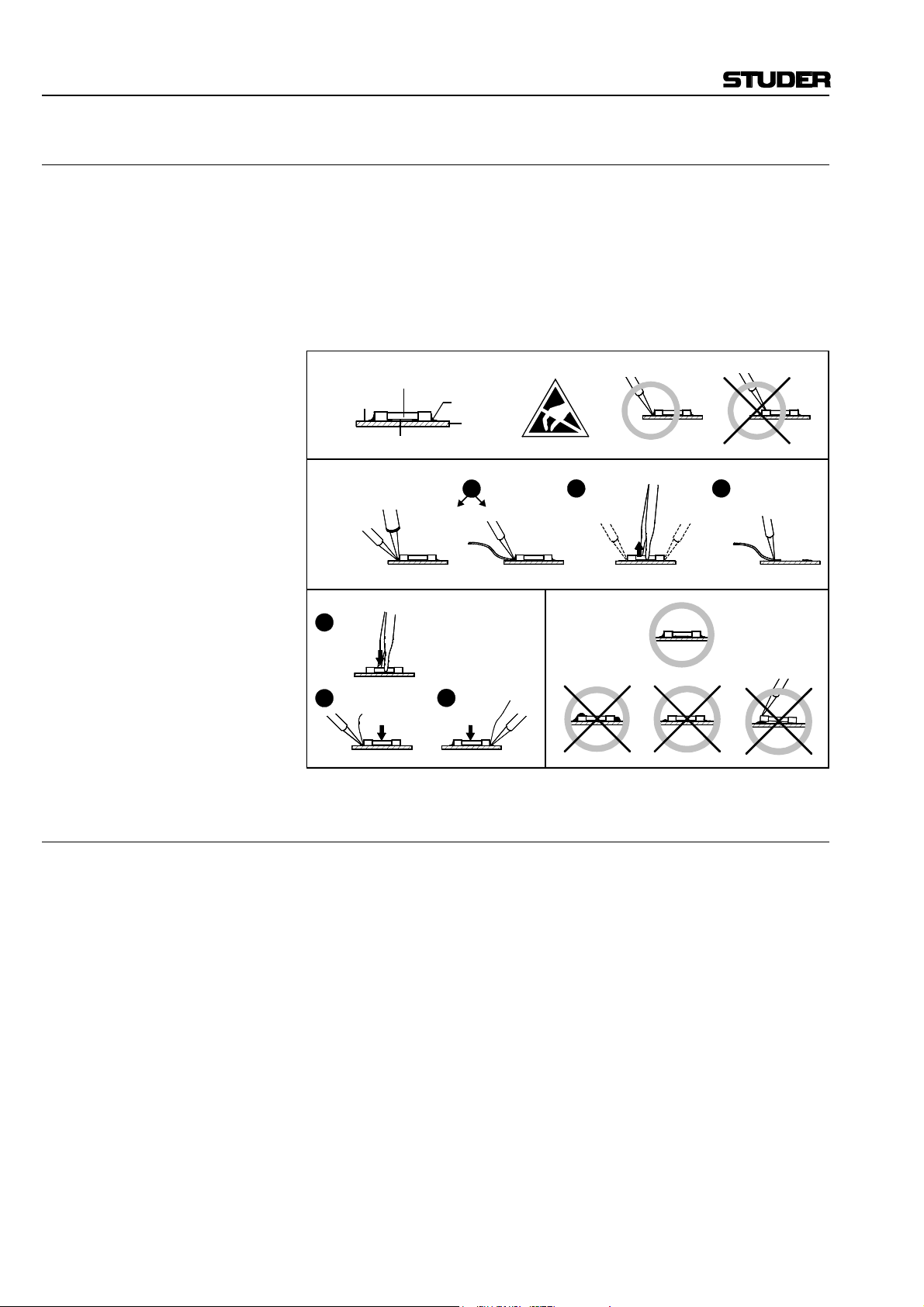
E1 SMD Components
Studer has no commercially available SMD components in stock for service purposes. For repair, the corresponding devices have to be purchased
locally. The specifications of special components can be found in the service manual.
SMD components should only be replaced by skilled specialists using appropriate tools. No warranty claims will be accepted for circuit boards that
have been damaged. Proper and improper SMD soldering joints are illustrated below.
Copper
Track
Dismounting
Soldering
Iron
Mounting
1
Solder
2
Ø 0.5...0.8 mm
SMD
Component
Solder
Adhesive
Desoldering
Iron
Desolder
Wick
3
Heating Time < 3 s per Side
PCB
1
Soldering Iron
32
Desolder
Wick
Heat and Remove Cleaning
Examples
F Disposal
Disposal of Packing Materials The packing materials have been selected with environmental and disposal
issues in mind. All packing material can be recycled. Recycling packing
saves raw materials and reduces the volume of waste.
If you need to dispose of the transport packing materials, please try to use
recyclable means.
Disposal of Used Equipment Used equipment contains valuable raw materials as well as materials that
must be disposed of professionally. Please return your used equipment via
an authorized specialist dealer or via the public waste disposal system, ensuring any material that can be recycled is.
Please take care that your used equipment cannot be abused. To avoid
abuse, delete sensitive data from any data storage media. After having disconnected your used equipment from the mains supply, make sure that the
mains connector and the mains cable are made useless.
VI

G Declarations of Conformity
G1 Class A Equipment - FCC Notice
This equipment has been tested and found to comply with the limits for a
Class A digital device, pursuant to Part 15 of the FCC Rules. These limits
are designed to provide a reasonable protection against harmful interference when the equipment is operated in a commercial environment. This
equipment generates, uses, and can radiate radio frequency energy and, if
not installed and used in accordance with the instruction manual, may
cause harmful interference to radio communications. Operation of this
equipment in a residential area is likely to cause harmful interference, in
which case the user will be required to correct the interference at his own
expense.
Caution: Any changes or modifications not expressly approved by the manufacturer
could void the user's authority to operate the equipment. Also refer to relevant information in this manual.
G2 CE Declaration of Conformity
Conformity
We,
Studer Professional Audio GmbH,
CH-8105 Regensdorf,
declare under our sole responsibility that the product
Studer OnAir 1000, Digital Mixing Console,
(starting with serial no. 1000)
to which this declaration relates, according to following regulations of EU
directives and amendments
• Low Voltage (LVD):
73/23/EEC + 93/68/EEC
• Electromagnetic Compatibility (EMC):
89/336/EEC + 92/31/EEC + 93/68/EEC
is in conformity with the following standards or normative documents:
• Safety:
EN 60950:2000 (Class I equipment)
• Safety of laser products:
EN 60825-1:1994 + A11 + A2, EN60825-2:2000
• EMC:
EN 55103-1/-2:1996, electromagnetic environments E2 and E4.
Regensdorf, December 18, 2000
B. Hochstrasser, President P. Fiala, Manager QA
VII

Appendix
Appendix 1: Air Temperature and Humidity
General
Normal operation of the unit or system is warranted under the following
ambient conditions defined by EN 60721-3-3, set IE32, value 3K3.
This standard consists of an extensive catalogue of parameters, the most
important of which are: ambient temperature +5...+40 °C, relative humidity
5...85% (i.e., no formation of condensation or ice); absolute humidity
1...25 g/m³; rate of temperature change < 0.5 °C/min. These parameters are
dealt with in the following paragraphs.
Under these conditions the unit or system starts and works without any
problem. Beyond these specifications, possible problems are described in
the following paragraphs.
Ambient Temperature
Units and systems by Studer are generally designed for an ambient temperature range (i.e. temperature of the incoming air) of +5...+40 °C. When
rack mounting the units, the intended air flow and herewith adequate cooling must be provided. The following facts must be considered:
• The admissible ambient temperature range for operation of the semiconductor components is 0 °C to +70 °C (commercial temperature range
for operation).
• The air flow through the installation must provide that the outgoing air
is always cooler than 70 °C.
• Average heat increase of the cooling air shall be about 20 K, allowing
for an additional maximum 10 K increase at the hot components.
• In order to dissipate 1 kW with this admissible average heat increase, an
air flow of 2.65 m³/min is required.
Example: A rack dissipating P = 800 W requires an air flow of 0.8 * 2.65 m³/min
which corresponds to 2.12 m³/min.
• If the cooling function of the installation must be monitored (e.g. for fan
failure or illumination with spot lamps), the outgoing air temperature
must be measured directly above the modules at several places within
the rack. The trigger temperature of the sensors should be 65 to 70 °C.
Frost and Dew
VIII
The unsealed system parts (connector areas and semiconductor pins) allow
for a minute formation of ice or frost. However, formation of dew visible
with the naked eye will already lead to malfunctions. In practice, reliable
operation can be expected in a temperature range above –15 °C, if the following general rule is considered for putting the cold system into operation:
If the air within the system is cooled down, the relative humidity rises. If it
reaches 100%, condensation will arise, usually in the boundary layer between the air and a cooler surface, together with formation of ice or dew at
sensitive areas of the system (contacts, IC pins, etc.). Once internal condensation occurs, trouble-free operation cannot be guaranteed, independent
of temperature.
Before putting into operation, the system must be checked for internal formation of condensation or ice. Only with a minute formation of ice, direct
Appendix
evaporation (sublimation) may be expected; otherwise the system must be
heated and dried while switched off.
A system without visible internal formation of ice or condensation should
be heated up with its own heat dissipation, as homogeneously (and subsequently as slow) as possible; the ambient temperature should then always
be lower than the one of the outgoing air.
If it is absolutely necessary to operate the cold system immediately within
warm ambient air, this air must be dehydrated. In such a case, the absolute
humidity must be so low that the relative humidity, related to the coldest
system surface, always remains below 100%.
Ensure that the enclosed air is as dry as possible when powering off (i.e.
before switching off in winter, aerate the room with cold, dry air, and remove humid objects as clothes from the room).
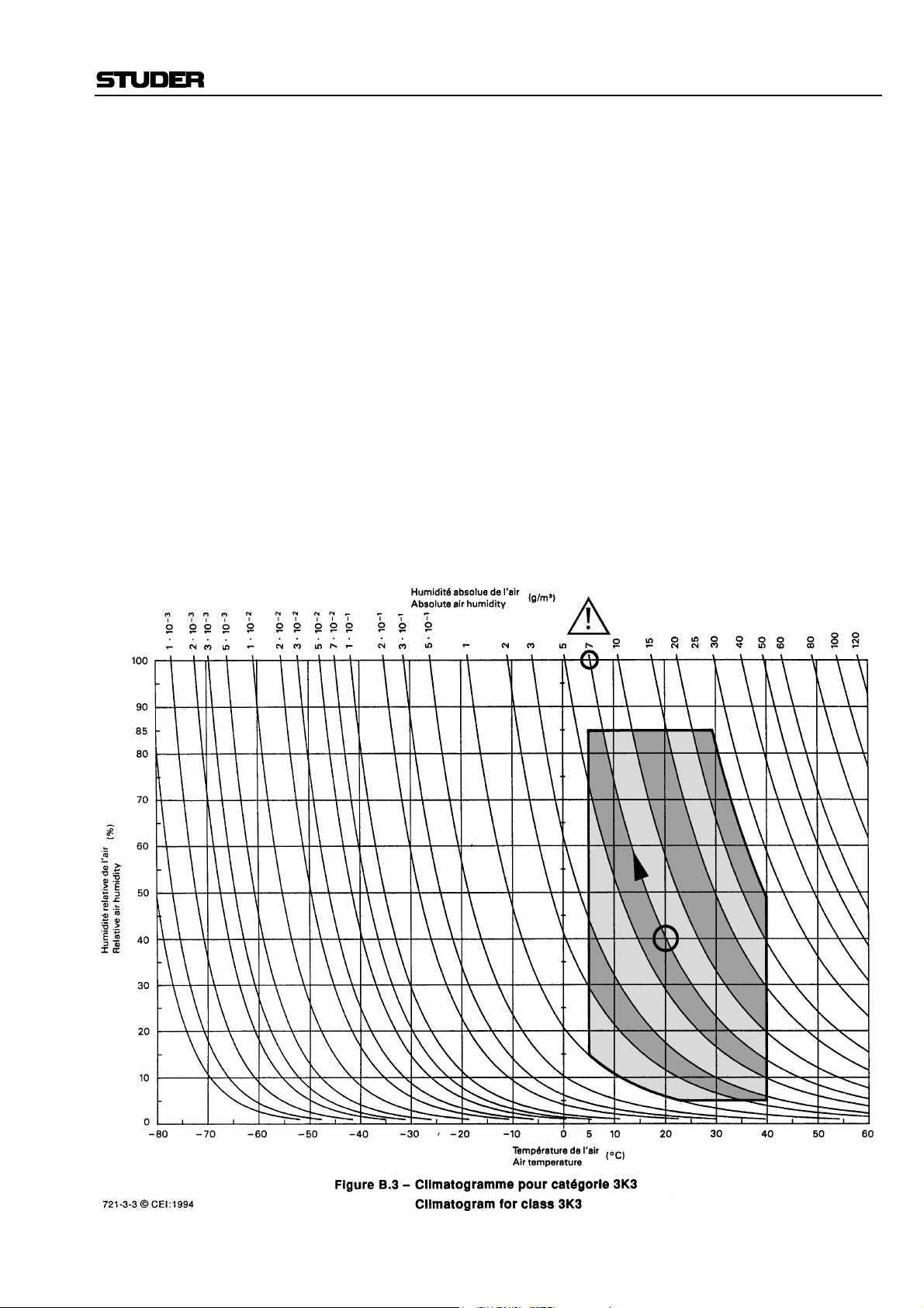
These relationships are visible from the following climatogram. For a controlled procedure, thermometer and hygrometer as well as a thermometer
within the system will be required.
Example 1: An OB-van having an internal temperature of 20 °C and relative humidity
of 40% is switched off in the evening. If temperature falls below +5 °C,
dew or ice will be forming.
Example 2: An OB-van is heated up in the morning with air of 20 °C and a relative
humidity of 40%. On all parts being cooler than +5 °C, dew or ice will be
forming.
IX
Appendix
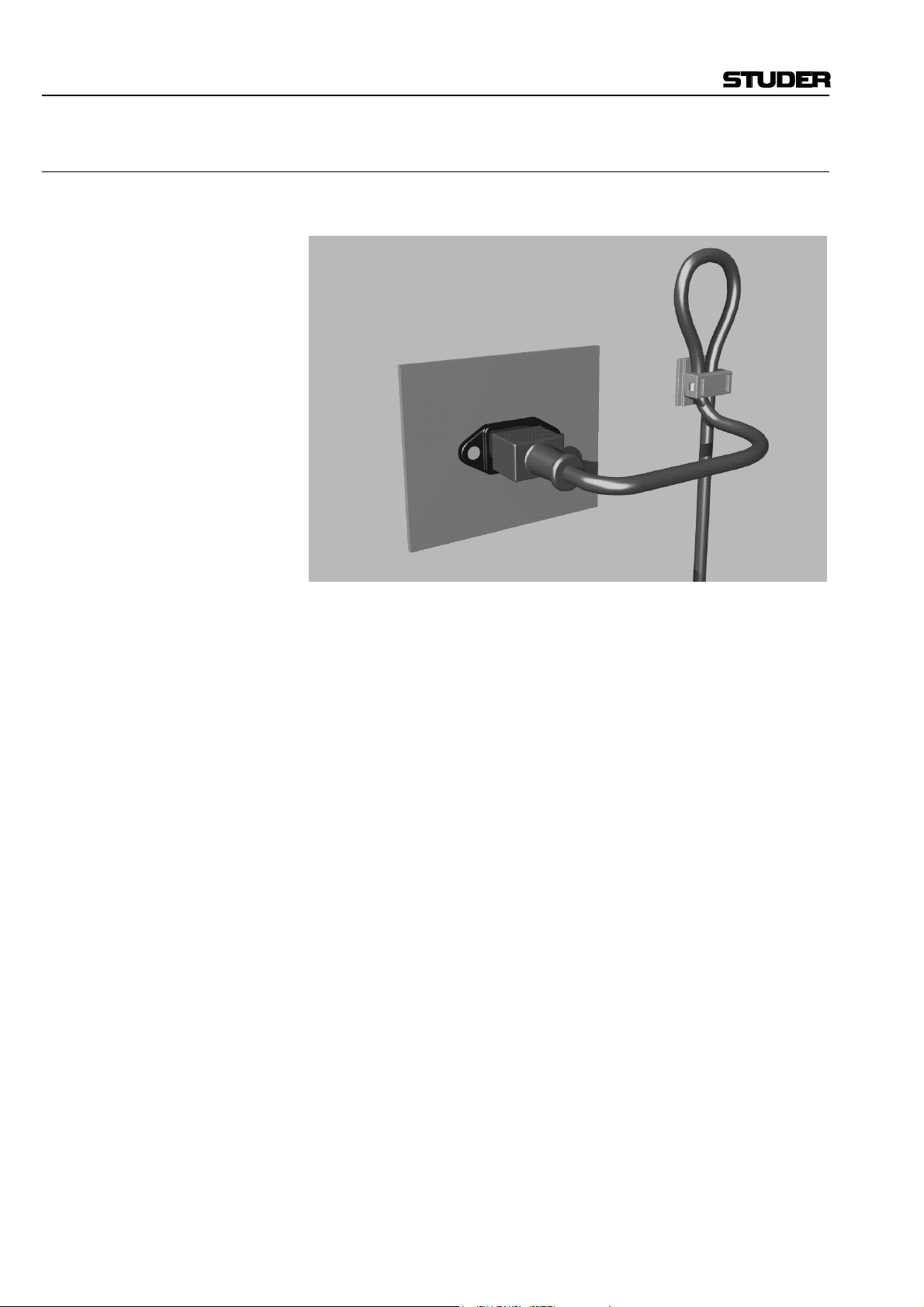
Appendix 2: Mains Connector Strain Relief
For anchoring connectors without a mechanical lock (e.g. IEC mains connectors), we recommend the following arrangement:
Procedure: The cable clamp shipped with your unit is auto-adhesive. For mounting
please follow the rules below:
• The surface to be adhered to must be clean, dry, and free from grease,
oil, or other contaminants. Recommended application temperature range
is +20...+40 °C.
• Remove the plastic protective backing from the rear side of the clamp
and apply it firmly to the surface at the desired position. Allow as much
time as possible for curing. The bond continues to develop for as long as
24 hours.
• For improved stability, the clamp should be fixed with a screw. For this
purpose, a self-tapping screw and an M4 bolt and nut are included.
• Place the cable into the clamp as shown in the illustration above and
firmly press down the internal top cover until the cable is fixed.
X

Appendix 3: Software License
Use of the software is subject to the Studer Professional Audio Software
License Agreement set forth below. Using the software indicates your acceptance of this license agreement. If you do not accept these license terms,
you are not authorized to use this software.
Under the condition and within the scope of the following Terms and Conditions, Studer Professional Audio GmbH (hereinafter “Studer”) grants the
right to use programs developed by Studer as well as those of third parties
which have been installed by Studer on or within its products. References
to the license programs shall be references to the newest release of a license program installed at the Customer’s site.
Programs Covered by the Agreement
License Programs of Studer The following Terms and Conditions grant the right to use all programs of
Studer that are part of the System and/or its options at the time of its delivery to the Customer, as well as the installation software on the original data
disk and the accompanying documentation (“License Material”). In this
Agreement the word “Programs” shall have the meaning of programs and
data written in machine code.
Using the software indicates your acceptance of this license agreement. If
you do not accept these license terms, you are not authorized to use this
software.
Appendix
Programs of Third Parties Programs of third parties are all programs which constitute part of the
Right of Use
System and/or its options at the time of delivery to the Customer but have
not been developed by Studer. The following conditions are applicable to
programs of third parties:
• The right to use third parties’ programs is governed by the License
Agreement attached hereto (if applicable), which is an integral part of
this Agreement. The Customer shall sign any and all License Agreements for all further programs of third parties installed on the system.
The Customer shall be deemed to have received all License Agreements
upon delivery of the system and/or its options.
• Studer shall accept no responsibility or liability for, and gives no warranties (express or implied) as to the programs of third parties. The
Customer waives any and all claims versus Studer for any consequential
damages, which might occur due to defects of these programs.
Principle Studer grants the Customer the non-exclusive right to use the License Ma-
terial in one copy on the system and/or its options as laid down by the
Sales Agreement concluded between the parties and all Terms and Conditions which shall be deemed to form and be read and construed as part of
the Sales Agreement. This right is assignable according to the “Assignability” paragraph hereinafter.
Customized Configurations The Customer is not entitled to alter or develop further the License Mate-
rial except within the expressly permitted configuration possibilities given
by the software installed on the system or elsewhere. All altered programs,
including but not limited to the products altered within the permitted configuration possibilities, are covered by this License Agreement.
XI

Appendix
Reverse Engineering Reverse engineering is only permitted with the express consent of Studer.
The consent of Studer can be obtained but is not limited to the case in
which the interface-software can not be provided by Studer. In any case
Studer has to be informed immediately upon complete or partial reverse
engineering.
Copying the License Material The Customer is entitled to make one copy of all or parts of the License
Material as is necessary for the use according to this Agreement, namely
for backup purposes. The Customer shall apply the copyright of Studer
found on the License Material onto all copies made by him. Records shall
be kept by the Customer regarding the amount of copies made and their
place of keeping. The responsibility for the original program and all copies
made lies with the Customer. Studer is entitled to check these records on
first request. Copies not needed anymore have to be destroyed immediately.
Disclosure of License Material The License Material is a business secret of Studer. The Customer shall not
hand out or in any way give access to parts or the complete License Material to third parties nor to publish any part of the License Material without
prior written consent of Studer. The Customer shall protect the License
Material and any copies made according to the paragraph above by appropriate defense measures against unauthorized access. This obligation of
non-disclosure is a perpetual obligation.
Third parties are entitled to have access to the License Material if they use
the License Material at the Customer’s site in compliance with this Agreement.
Under no circumstance are third parties entitled to have access to the installation software on the original data media. The Customer shall safeguard the original data media accordingly.
Assignability The rights granted to the Customer according to this License Agreement
shall only be assignable to a third party together with the transfer of the
system and/or its options and after the prior written consent of Studer.
Rights to License Material
With the exception of the right of use granted by this License Agreement
all proprietary rights to the License Material, especially the ownership and
the intellectual property rights (such as but not limited to patents and copyright) remain with Studer even if alterations, customized changes or
amendments have been made to the License Material.
Studer’s proprietary rights are acknowledged by the Customer. The Customer shall undertake no infringements and make no claims of any patent,
registered design, copyright, trade mark or trade name, or other intellectual
property right.
Warranty, Disclaimer, and Liability
For all issues not covered herewithin, refer to the “General Terms and
Conditions of Sales and Delivery” being part of the sales contract.
XII

NEW FEATURES WITH SW V4.02/V4.03
1 Momentary/Latching Key Functions
1.1 PFL and Talkback Keys
Latching: If a PFL key or one of the talkback keys (N–1 A, N–1 B, AUX 1, AUX 2,
or STUDIO) is pressed for less than 0.2 s, the function is now latching, and
the key is illuminated. To release the function, an other short press of the
key is required.
The same functionality applies for the F1...F5 keys if configured as additional talkback keys. For this purpose, please refer to the “MONITOR
EXPANDER page, Talkback Functions” paragraph below.
Momentary: When pressing a PFL or TB key longer than 0.2 s, it acts as a momentary
key, i.e., the function is automatically canceled upon releasing the key.
Basic information on this subject to be found in chapters: 3.1.4 / 6.1 / 6.3
OnAir 1000 Digital Mixing Console
1.2 Monitoring Keys
Mutually Releasing / Latching: If one of the Monitoring Selector keys is pressed for less than 0.2 s, the
former monitoring source selection is canceled, and the new monitoring
source selection becomes active. The selection is latching and the key is illuminated until any other Monitoring Selector key is pressed.
Mutually Releasing / Momentary:If one of the Monitoring Selector keys is pressed for longer than 0.2 s, it acts as
a momentary key. The former monitoring source selection is canceled, and
the new monitoring source selection becomes active. Upon releasing the key,
the former monitoring source selection is reactivated.
Uhm... This may sound a bit confusing, but in everyday use it is a very convenient
feature – just give it a try!
2 Talkback and PFL Signaling
2.1 Talkback Signaling from CR to Studio, and Vice Versa
CR to Studio: When talkback from the control room (CR) to the studio is activated, pin 23
of the STUDIO MON CTRL connector is activated (i.e. pulled to ground).
This pin was formerly labeled as “Spare OUT 1”. Now it can be used for
illuminating the CR lamp on an external talkback box.
Please refer to the pin assignment diagram and table on the next page.
Studio to CR: When talkback from the studio to the CR is activated (e.g. when using the
external talkback box), the TALK BACK STUDIO key in the console’s
central section is illuminated.
Basic information on this subject to be found in chapters: 3.1.4 / 6.3 /
14.11
Date printed: 12.07.04 SW V 4.02/V4.03 New Features 1
OnAir 1000 Digital Mixing Console
2.2 PFL Signaling
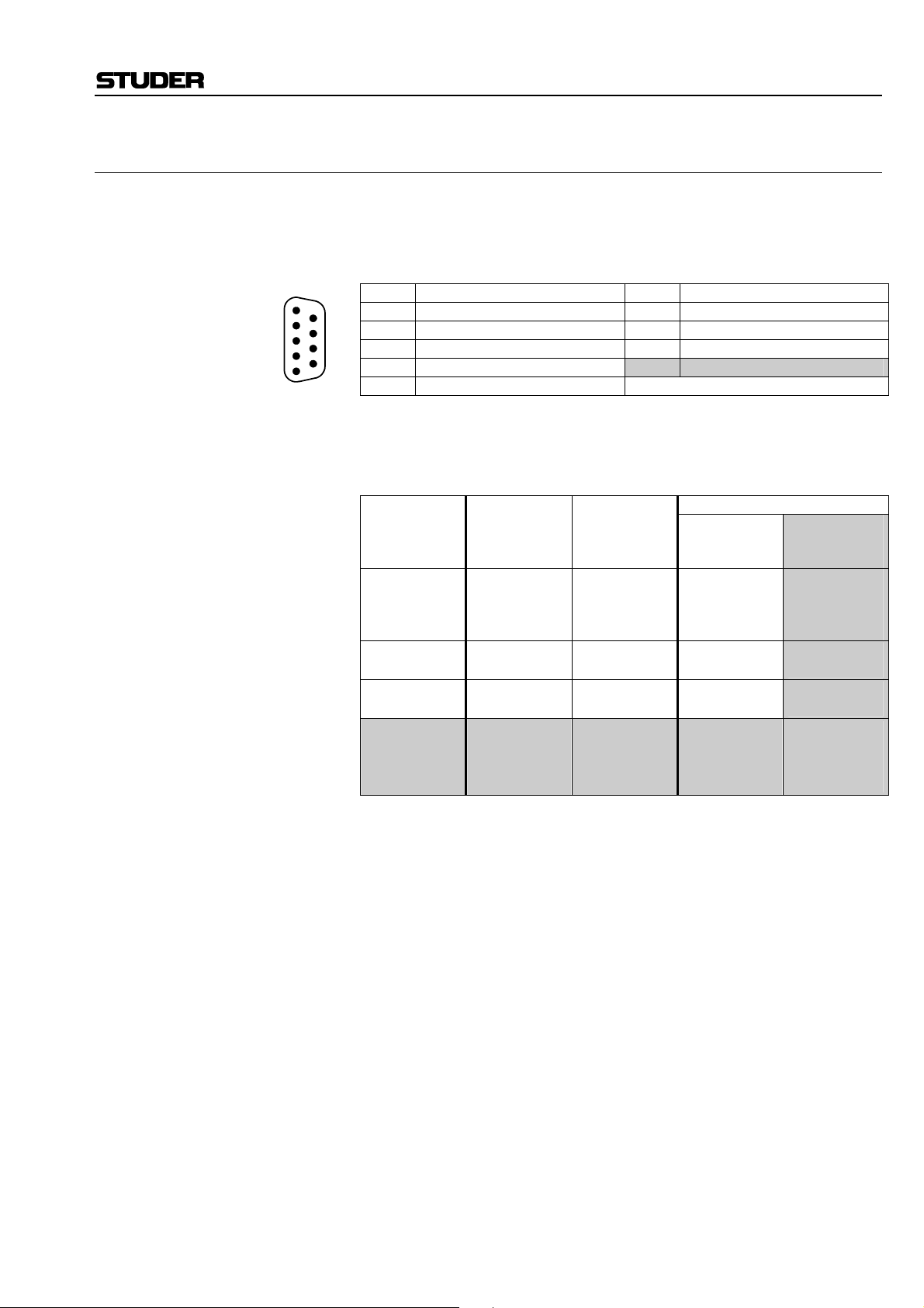
When a PFL key is activated, pin 11 of the STUDIO MON CTRL connec-
tor is activated (i.e. pulled to ground). This pin was formerly labeled as
STUDIO MON CTRL (D-type, 25 pin, male):
Pin Signal Pin Signal Pin Signal
1 +5 V SUPPLY 10 Lamp EXTERN 19 Switch TB TO TEL2
2 COMMON 11 Lamp PFL SIGN. 20 Lamp PGM
3 Switch AUX1 12 n.c. 21 Lamp AUX2
4 Switch OFF AIR 13 GND 22 Lamp PFL
5 Switch EXTERN 14 +5 V SUPPLY 23 Lamp TB T O S T U D I O
6 Switch TB TO TEL1 15 Switch PGM
7 n.c. 16 Switch AUX2
8 Lamp AUX1 17 Switch PFL 25 GND
9 Lamp OFF AIR 18 Switch TB TO CR
13
12
11
10
9
8
7
6
5
4
3
2
1
“Spare OUT 2”.
25
24
23
22
21
20
19
18
17
16
15
14
24 Lamp STUDIO MIC
ON
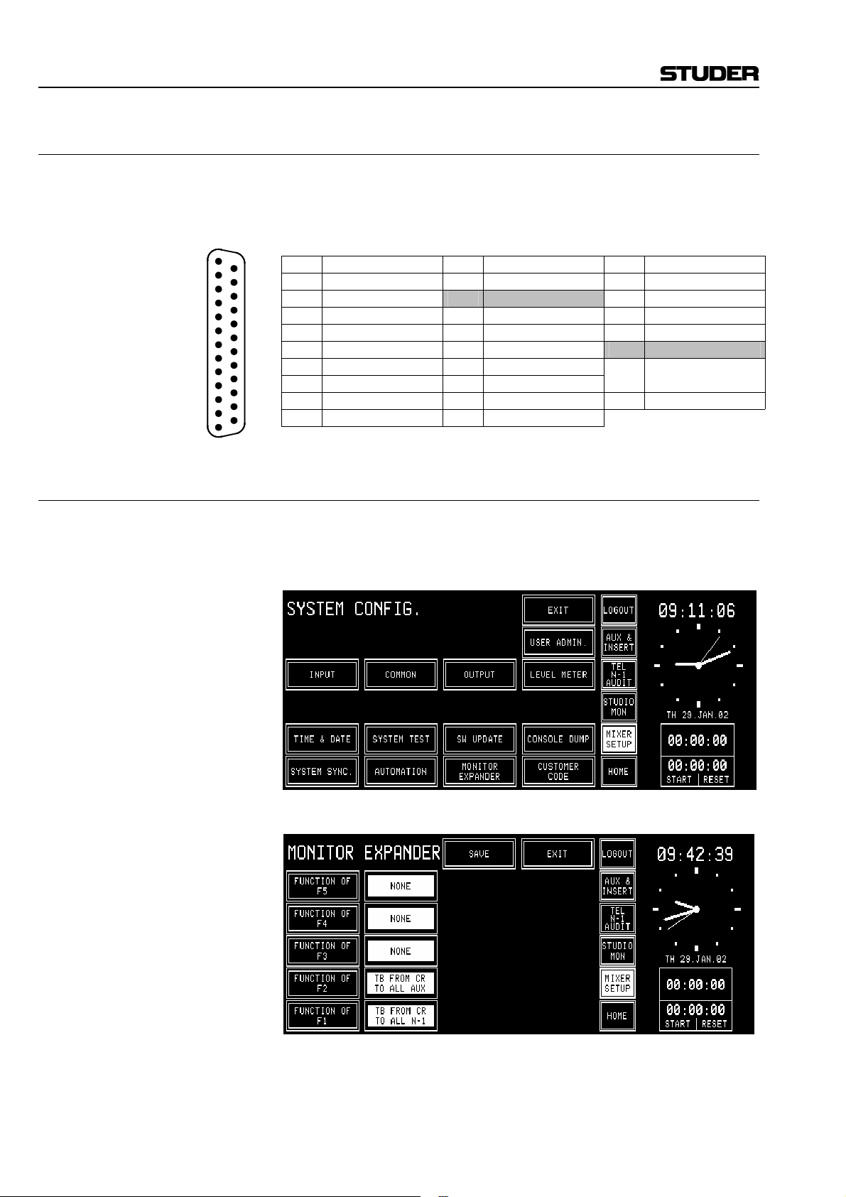
3 MONITOR EXPANDER Page, Talkback Functions
The MONITOR EXPANDER page, possibly known from your experience
with OnAir 2000M2 consoles, can now be opened on the OnAir 1000 consoles as well. For this purpose, the SYSTEM CONFIG. Page has an additional “MONITOR EXPANDER” button, as shown below:
When touching this button, the MONITOR EXPANDER page opens and
allows to assign three different functions to any of the F1...F5 buttons:
TB FROM CR TO ALL AUX, TO ALL N–1, or TO ALL (meaning all
AUX and all N–1), or NONE (no function at all).
However, no Monitor Extension module can be installed in an OnAir 1000
console, which means that no other functions (as known from OnAir
2000M2 consoles) can be configured.
2 New Features
SW V 4.02/V4.03 Date printed: 13.04.2005
OnAir 1000 Digital Mixing Console
4 Additional REC Signaling Output
An additional REC signaling output has been provided on pin 9 of the
SIGN. connector (formerly labeled as “Spare OUT”) to extend the on-air
SIGN. (D-type, 9 pin, male):
Pin Signal Pin Signal
1 +5 V SUPPLY 6 COMMON
2 ON AIR IN – 7 Spare IN – or Ext. CR DIM IN – *
3 CR MIC OUT 8 STUDIO MIC OUT
4 PGM OUT 9 REC OUT
5 GND
5
4
3
2
1
For the ON AIR INDICATION setting on the COMMON SETTINGS
In other words:
• For the 1
• For the 2
• For the 3
• For the 4
Basic information on this subject to be found in chapter 11.2.2
signaling features.
9
8
7
6
* depending on Customer Code setting
page, a fourth selection item ( PROGRAM/ REC) was created. Depending
on this setting, the two signaling outputs are active according to the following table:
ON AIR
INDICATION
setting
1)
PROGRAM
AND REC
2)
PROGRAM
3)
REC
4)
PROGRAM
/ REC
(new setting)
st
setting, both signaling outputs are active whenever any audio
signal is routed either to the program or the record output (or both).
nd
setting, only the PGM OUT signaling output is active while an
PROGRAM
output on-air
0
1
0
1
0
1
x
x
0
1
0
1
REC
output on-air
0
0
1
1
x
x
0
1
0
0
1
1
(PGM OUT)
SIGN output:
Pin 4
0
1
1
1
0
1
0
0
0
1
0
1
(REC OUT)
(new output)
audio signal is routed to the program output. An audio signal routed to the
record output has no effect.
rd
setting, only the REC OUT signaling output is active while an
audio signal is routed to the record output. An audio signal routed to the
program output has no effect.
th
(new) setting, only the PGM OUT signaling output is active
while an audio signal is routed to the program output, and only the REC
OUT signaling output is active while an audio signal is routed to the record
output. If audio signals are routed to both the program and the record outputs, both the PGM OUT and REC OUT signaling outputs are active.
Pin 9
0
1
1
1
0
0
0
1
0
0
1
1
Date printed: 13.04.2005 SW V 4.02/V4.03 New Features 3

OnAir 1000 Digital Mixing Console
5 Additional Customer Codes
Code 0x00000800: Used to disable dimming of the CR monitor speakers during talkback from
the studio to the control room.
Code 0x00001000: Used to disable dimming of the studio monitor speakers during talkback
from the control room to the studio.
Code 0x00002000: Used to swap the functions of the PFL and the OFF keys next to the faders,
regardless whether they are used for the standard PFL and OFF functions,
or whether other functions are configured for any of these keys.
Basic information on this subject to be found in chapter 9
Code 0x00004000: If this code is active, whenever a channel is activated by moving its fader up
from its lower stop while it is switched ON (or the other way round, by
switching the channel ON while its fader is positioned above the lower stop),
this channel’s Channel Control page pops up automatically and allows for
immediate changes of the channel settings. This Channel Control page remains displayed until another channel is activated, or until another page is
selected using one of the five buttons next to the clock dial.
Code 0x00008000: If this code is active, the status of the channel ON/OFF switch of channels
currently not routed to the console surface will be saved in the flash memory
when powering the console off. At power on, the ON or OFF status of these
channels will automatically be re-established.
If this code is inactive, the channels not routed to the console surface will
always be set to OFF at power on.
Basic information on Customer Code to be found in chapter 11.2.11
4 New Features SW V 4.02/V4.03 Date printed: 12.07.04

OnAir 1000 Digital Mixing Console
CONTENTS
1 Introduction.................................................................................................................................................................... 1-1
1.1 Block Diagram OnAir 1000, SW V4.0.....................................................................................................................1-2
1.2 Definition of Terms ..................................................................................................................................................1-4
2 General ............................................................................................................................................................................2-1
2.1 Utilization for the Purpose Intended ......................................................................................................................... 2-1
2.2 First Steps ................................................................................................................................................................. 2-1
2.2.1 Unpacking and Inspection.................................................................................................................................2-1
2.2.2 Installation ........................................................................................................................................................2-1
2.2.3 Adjustments, Repair.......................................................................................................................................... 2-2
2.2.4 PC-Card ............................................................................................................................................................ 2-2
2.3 Technical Specifications ........................................................................................................................................... 2-3
3 Operating Concept .........................................................................................................................................................3-1
3.1 Operating Elements................................................................................................................................................... 3-1
3.1.1 Power Switch .................................................................................................................................................... 3-1
3.1.2 Touch-Screen Unit ............................................................................................................................................3-2
3.1.3 Metering Section............................................................................................................................................... 3-3
3.1.4 Monitoring and Talkback Section ..................................................................................................................... 3-4
3.1.5 Fader Section .................................................................................................................................................... 3-6
3.2 Connector Panels ...................................................................................................................................................... 3-8
4 Channel Functions..........................................................................................................................................................4-1
4.1 Keys ..........................................................................................................................................................................4-1
4.2 Faders........................................................................................................................................................................4-2
4.3 LED Indicators .........................................................................................................................................................4-2
4.4 Channel Control Page, Microphone Input ................................................................................................................4-4
4.5 Channel Control Page, Line Input............................................................................................................................. 4-5
4.6 EQ/Filter Page, Microphone Input............................................................................................................................ 4-7
4.7 EQ/Filter Page, Analog Line/Digital Input ............................................................................................................... 4-8
Date printed: 23.10.03 SW V 4.0 Contents Part 1 0-1

OnAir 1000 Digital Mixing Console
5 Master Functions............................................................................................................................................................ 5-1
5.1 Login/Logout............................................................................................................................................................ 5-1
5.2 AUX and Insert Control ........................................................................................................................................... 5-2
5.3 N–1/Audition Bus and Telephone Hybrid Control................................................................................................... 5-3
5.3.1 N–1 and Audition Bus Routing ........................................................................................................................ 5-4
5.4 Studio Monitoring .................................................................................................................................................... 5-5
5.5 Mixer Setup.............................................................................................................................................................. 5-6
5.6 Snapshots.................................................................................................................................................................. 5-7
5.6.1 Recall a Snapshot from Memory ...................................................................................................................... 5-7
5.6.2 Save a Snapshot to Memory............................................................................................................................. 5-8
5.6.3 Delete a Snapshot from Memory...................................................................................................................... 5-8
5.7 Mic Settings ............................................................................................................................................................. 5-9
5.7.1 Recall a Mic Setting from Memory.................................................................................................................. 5-9
5.7.2 Save a Mic Setting to Memory....................................................................................................................... 5-10
5.7.3 Delete a Mic Setting from Memory................................................................................................................ 5-10
5.8 Routing................................................................................................................................................................... 5-11
5.8.1 Channel Routing............................................................................................................................................. 5-11
5.8.2 Recall a Channel Routing from Memory........................................................................................................ 5-14
5.8.3 Save a Channel Routing to Memory............................................................................................................... 5-14
5.8.4 Delete a Channel Routing from Memory (Administrator Only) ..................................................................... 5-15
5.8.5 Channel Routing Administration.................................................................................................................... 5-15
5.9 Using PC-Cards...................................................................................................................................................... 5-16
5.9.1 Load a Snapshot/Mic Setting/Channel Routing from PC-Card ...................................................................... 5-16
5.9.2 Save a Snapshot/Mic Setting/Channel Routing to PC-Card ........................................................................... 5-17
5.9.3 Delete a Snapshot/Mic Setting/Channel Routing from PC-Card .................................................................... 5-17
5.10 Administrator ......................................................................................................................................................... 5-18
5.10.1 Features .......................................................................................................................................................... 5-18
5.10.2 Admin Selection of Snapshots/Mic Settings/Channel Routings ..................................................................... 5-19
5.10.3 Users with and without a Password ................................................................................................................ 5-20
5.11 User Administration ............................................................................................................................................... 5-21
5.12 System Configuration............................................................................................................................................. 5-21
5.13 Watch and Stopwatch............................................................................................................................................. 5-22
5.13.1 Watch ............................................................................................................................................................. 5-22
5.13.2 Fader Stopwatch ............................................................................................................................................. 5-23
5.13.3 User Stopwatch .............................................................................................................................................. 5-23
5.14 PGM and REC Master Faders................................................................................................................................ 5-24
5.14.1 Fixed Master Levels ....................................................................................................................................... 5-24
6 Monitoring ...................................................................................................................................................................... 6-1
6.1 Control Room Monitoring........................................................................................................................................ 6-1
6.2 Studio Monitoring .................................................................................................................................................... 6-3
6.3 Talkback................................................................................................................................................................... 6-4
6.3.1 Talkback Settings ............................................................................................................................................. 6-5
6.4 External PFL ............................................................................................................................................................ 6-6
7 Signaling.......................................................................................................................................................................... 7-1
0-2 Contents Part 1 SW V 4.0 Date printed: 23.10.03

OnAir 1000 Digital Mixing Console
8 Machine Control.............................................................................................................................................................8-1
8.1 Keys and LEDs ......................................................................................................................................................... 8-1
8.2 Control Outputs ........................................................................................................................................................8-3
8.2.1 CTRL OUT1..................................................................................................................................................... 8-3
8.2.2 CTRL OUT2..................................................................................................................................................... 8-3
8.3 Control Inputs ........................................................................................................................................................... 8-4
8.3.1 CTRL IN........................................................................................................................................................... 8-4
8.3.2 EXT PFL Input ................................................................................................................................................. 8-4
8.4 CTRL OUT1/2 & CTRL IN Application Examples ................................................................................................. 8-5
9 Automation...................................................................................................................................................................... 9-1
9.1 Introduction ..............................................................................................................................................................9-1
9.2 Features of the OnAir 1000 CAB Support................................................................................................................ 9-1
9.3 Application Handling................................................................................................................................................ 9-2
9.3.1 Configuration for Automation Control .............................................................................................................9-2
9.3.2 Communication Time-Out ................................................................................................................................9-2
9.3.3 Output Selection ...............................................................................................................................................9-3
9.3.4 Start a New Title from Schedule.......................................................................................................................9-3
9.3.5 Indication of the Currently Playing Input Line .................................................................................................9-4
9.3.6 Pre-Listening..................................................................................................................................................... 9-4
9.3.7 Time Synchronization.......................................................................................................................................9-4
10 User Modes................................................................................................................................................................10-1
10.1 Purpose of User Modes........................................................................................................................................... 10-1
10.2 Access to Configurable Functions of the Console ..................................................................................................10-2
10.3 User Administration................................................................................................................................................ 10-4
10.4 Administration Functions........................................................................................................................................ 10-5
10.5 Log-in Procedure and Defaults ............................................................................................................................... 10-7
11 Configuration............................................................................................................................................................11-1
11.1 Configuration Handling ..........................................................................................................................................11-1
11.2 Configuration Procedure......................................................................................................................................... 11-1
11.2.1 Input................................................................................................................................................................11-3
11.2.2 Common Settings ............................................................................................................................................ 11-6
11.2.3 Output .............................................................................................................................................................11-7
11.2.4 Level Meter.....................................................................................................................................................11-7
11.2.5 Time and Date................................................................................................................................................. 11-8
11.2.6 System Test.....................................................................................................................................................11-9
11.2.7 Software Update ........................................................................................................................................... 11-10
11.2.8 Console Dump .............................................................................................................................................. 11-10
11.2.9 System Synchronization................................................................................................................................11-11
11.2.10 Automation.................................................................................................................................................... 11-12
11.2.11 Customer Code..............................................................................................................................................11-13
Date printed: 23.10.03 SW V 4.0 Contents Part 1 0-3

OnAir 1000 Digital Mixing Console
12 SW Update.................................................................................................................................................................12-1
12.1 Software Structure ..................................................................................................................................................12-1
12.1.1 CPU Software Package...................................................................................................................................12-1
12.1.2 DSP Software Package ...................................................................................................................................12-1
12.1.3 Important Information for Software Update to V4.0......................................................................................12-1
12.2 SW Update Procedure.............................................................................................................................................12-2
12.2.1 Error Handling................................................................................................................................................12-4
13 System Diagnostics and Error Handling ................................................................................................................13-1
13.1 Error, Warning, and Information Messages............................................................................................................13-1
13.1.1 System Diagnostics.........................................................................................................................................13-2
13.2 Indication on Failure of Restricted Functions.........................................................................................................13-6
13.3 System Test.............................................................................................................................................................13-7
13.3.1 Buttons/Faders Test.........................................................................................................................................13-7
13.3.2 Display Test....................................................................................................................................................13-8
13.3.3 PC-Card Test...................................................................................................................................................13-9
13.3.4 SW Versions Display......................................................................................................................................13-9
14 Wiring and Hardware information.........................................................................................................................14-1
14.1 DC Supply...............................................................................................................................................................14-1
14.2 Redundant Power Supply........................................................................................................................................14-3
14.3 Mic Input.................................................................................................................................................................14-6
14.4 Analog Line Input...................................................................................................................................................14-8
14.5 Digital Input............................................................................................................................................................14-8
14.6 TB Mic Input ..........................................................................................................................................................14-9
14.7 Telephone Hybrid Interface ..................................................................................................................................14-10
14.8 Analog Output.......................................................................................................................................................14-11
14.9 Digital Output .......................................................................................................................................................14-11
14.10 Analog Insert.........................................................................................................................................................14-12
14.11 Monitoring............................................................................................................................................................14-13
14.12 Serial Interface......................................................................................................................................................14-19
14.13 Clock Sync Interface.............................................................................................................................................14-19
14.14 Time Sync Interface..............................................................................................................................................14-20
System Wiring, Standard Version.....................................................................................................................................14-21
System Wiring, Redundant Supply Version.....................................................................................................................14-22
0-4 Contents
SW V 4.0 Date printed: 14.04.2005

OnAir 1000 Digital Mixing Console
15 Dip Switches and Jumpers ....................................................................................................................................... 15-1
15.1 Input Units .............................................................................................................................................................. 15-1
15.2 TB Mic Input Units................................................................................................................................................. 15-2
15.3 Telephone Hybrid Interface .................................................................................................................................... 15-3
15.4 Analog Output Units...............................................................................................................................................15-4
15.5 Digital Output Units................................................................................................................................................ 15-5
15.6 Insert Unit ............................................................................................................................................................... 15-5
15.7 Clock Sync Interface............................................................................................................................................... 15-5
15.8 Time Sync Interface................................................................................................................................................15-6
15.9 Monitoring Controller PCB ....................................................................................................................................15-7
15.10 Level Meter PCB .................................................................................................................................................... 15-7
15.11 PSU Sub Board.......................................................................................................................................................15-7
15.12 DSP PCB ................................................................................................................................................................15-8
15.13 Control Front Board I .............................................................................................................................................15-8
16 Index ..........................................................................................................................................................................16-1
Date printed: 23.10.03 SW V 4.0 Contents Part 1 0-5

OnAir 1000 Digital Mixing Console
0-6 Contents Part 1 SW V 4.0 Date printed: 23.10.03
1 INTRODUCTION
OnAir 1000 Digital Mixing Console
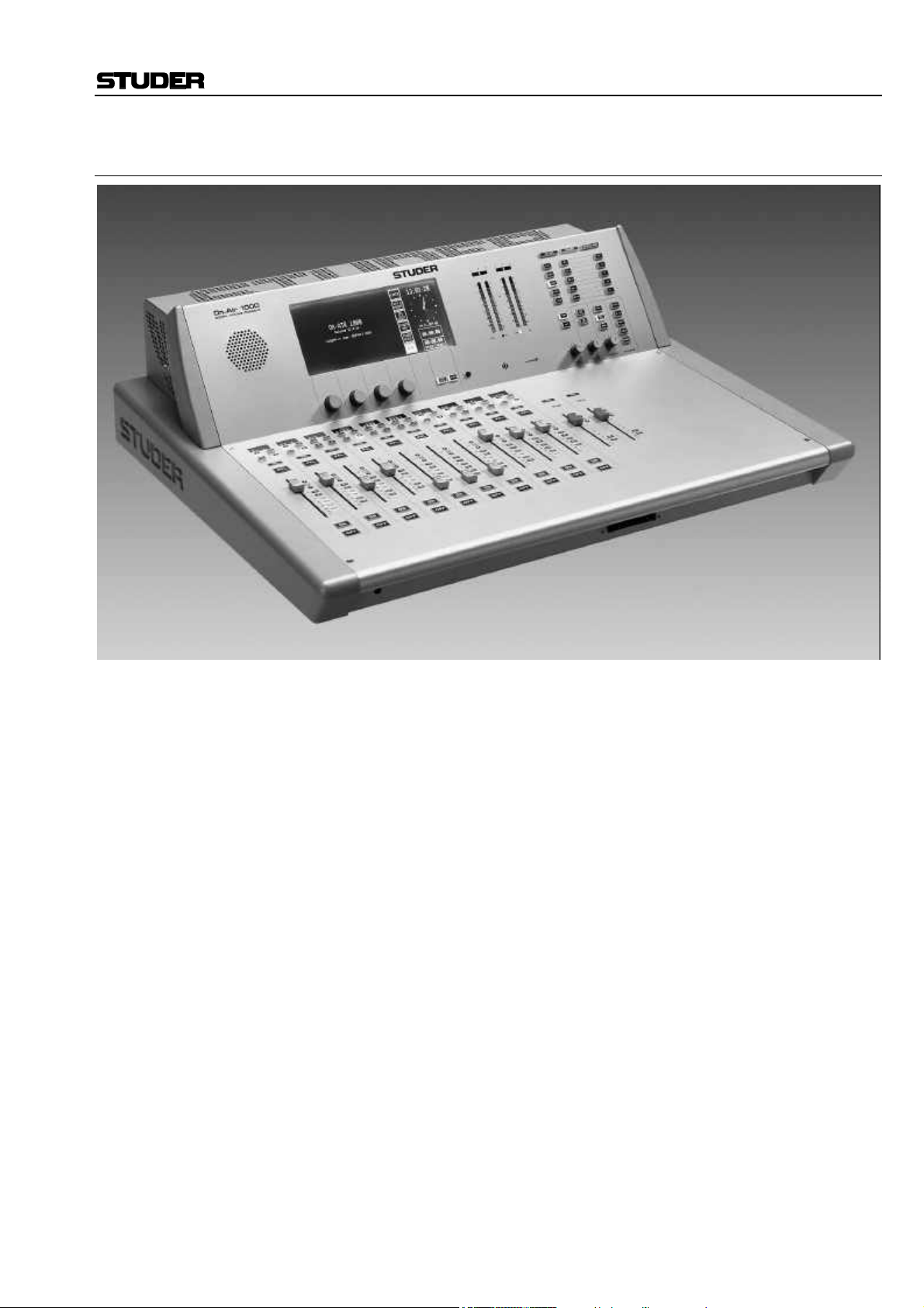
The OnAir 1000 is a smart but yet powerful digital mixing console for
“on-air” and small recording and editing studio applications. It has ten input channels, each with two physical inputs, and two master faders.
There are two different basic versions available:
• An analog-biased version with five analog stereo line and two digital
input channels, and
• A digital-biased version with two analog stereo line and five digital
input channels.
Both versions feature three mono microphone input channels with
switchable high-pass filter and phantom power. Both versions can be ordered with double, redundant mains power supply. For more information
on this subject, please refer to chapter 14.2.
The OnAir 1000 can be integrated seamlessly with a broadcast automation
system (CAB) like Studer’s DigiMedia.
The OnAir 1000 is based on a touch-screen user interface. Only the most
important functions have hardware control elements, making it very easy
to use. It has everything integrated in a single, lightweight console and
does not need any external racks or power supplies (except the Redundant
Supply versions, refer to chapter 14.2).
Since it is fully digital, it can individually be adapted to the current user
using snapshot automation. Extensive configuration possibilities allow the
OnAir 1000 to be integrated into almost any broadcast studio environment.
For an overview, please refer to the OnAir 1000 block diagram located on
the following two pages.
Date printed: 23.10.03 SW V 4.0 Intro 1-1
OnAir 1000 Digital Mixing Console
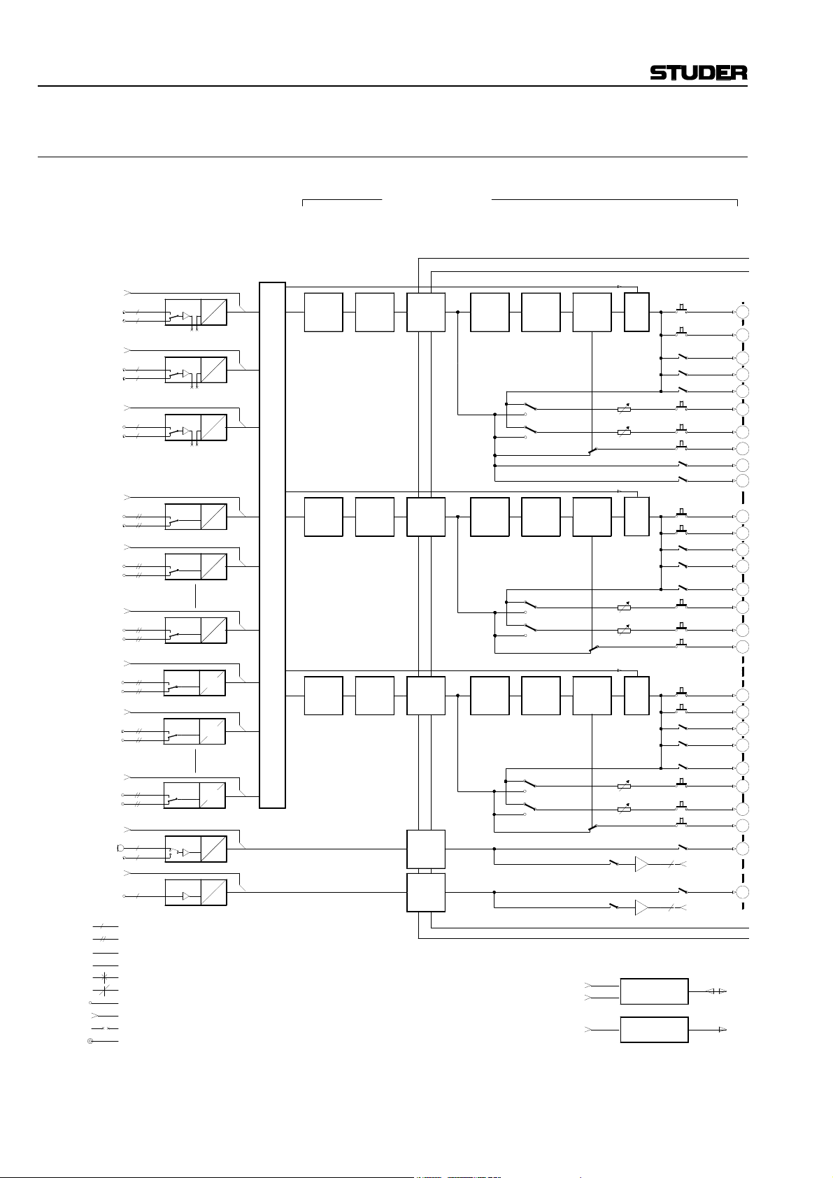
1.1 Block Diagram OnAir 1000, SW V4.0
INPUTS
CTRL I/O
DJ MIC 1
CTRL I/O
GUEST MIC.1
STUDIO MIC.1
CTRL I/O
GUEST MIC.2
STUDIO MIC.2
CTRL I/O
ANALOG STEREO INP 1
ANALOG STEREO INP 2
CTRL I/O
ANALOG STEREO INP 3
ANALOG STEREO INP 4
CTRL I/O
* ANALOG STEREO INP 9
* ANALOG STEREO INP 10
CTRL I/O
DIGITAL STEREO INP 1
DIGITAL STEREO INP 2
CTRL I/O
DIGITAL STEREO INP 3
DIGITAL STEREO INP 4
CTRL I/O
# DIGITAL STEREO INP 9
# DIGITAL STEREO INP 10
CTRL I/O
TB MIC
CTRL I/O
TB MIC
STUDIO
a
d
a
a
a
a
a
a
a
a
a
a
a
a
d
d
d
d
d
d
a
a
CR
a
MONO LINE
STEREO LINE
ANALOG SIGNAL
DIGITAL SIGNAL (AES/EBU)
CONFIG SELECTION
MONITOR SELECTOR
XLR CONNECTOR
D-TYPE CONNECTOR
BANTAM JACK
HEADPHONE JACK SOCKET
INPUT
PCBs
INSERT
PREAMP 2
INSERT
PREAMP 3
INSERT
HL INP 1
HL INP 2
APREAMP 1
D
A
D
A
D
A
D
A
D
INPUT CHANNEL 1
DC REJ
PHASE
INPUT CHANNEL 4
DIG PAD
PHASE
INPUT ROUTER
A
HL INP 5
AES INP 1
AES INP 2
AES INP 5
D
*
INPUT CHANNEL 10
D
SFC
D
D
SFC
D
D
SFC
D
APREAMP
D
APREAMP
D
* ANALOG-BIASED VERSION (6 mic, 10 analog, and 4 digital inputs)
# DIGITAL-BIASED VERSION (6 mic, 4 analog, and 10 digital inputs)
*** IF "PFL CUT ON CHANNEL ACTIVE" IS YES
DC REJ
DIG PAD
PHASE
TB INPUT CHANNELS
INPUT CHANNELS
FILTER/
EQU.DIG PAD
FILTER/DC REJ
FILTER/
EQU.
INSERT
INSERT
INSERT
INSERT
BALANCEFADERINSERT
AF
PF
AF
PF
FADER BALANCEEQU.
AF
PF
AF
PF
FADER BALANCE
AF
PF
AF
PF
COMMUNICATION I/O
TIME SYNC INP
RS 232
RS 422
CHANNEL
ON
CHANNEL
ON
CHANNEL
ON
***
***
CHANNEL ON
***
CHANNEL ON
CHANNEL ON
AUX1
AUX2
AUX1
AUX2
AUX1
AUX2
MUTE
MUTE
MUTE
RS 232/422
INTERFACE
TIME SYNC
INTERFACE
Σ PROGRAM
Σ RECORD
AUDITION
Σ
N–1 A
N–1 B
AUX 1
AUX 2
PFL
TB TO STUDIO
TB TO CR
PROGRAM
Σ
RECORD
Σ
AUDITION
Σ
N–1 A
N–1 B
AUX 1
AUX 2
PFL
PROGRAM
Σ
Σ RECORD
AUDITION
Σ
N–1 A
N–1 B
AUX 1
AUX 2
PFL
TB TO STUDIO
TB TO EXT
TB TO CR
TB TO EXT
+
+
+
+
+
+
+
+
+
+
+
+
+
+
+
+
+
+
BUS
+
+
+
+
+
+
+
+
+
+
1-2 Intro SW V 4.0 Date printed: 23.10.03

OnAir 1000 Digital Mixing Console
MASTER AND MONITORING
MAIN OUTPUTS
METER 1 METER 2
PPM / VU
BARGRAPH BARGRAPH
RETURNSEND
PROGRAM
+
+
+
+
+
Σ FADER PGM
Σ
Σ AUDITION
Σ N–1 A
Σ N–1 B
FADER REC
INSERT
INSERT
DIM
DIM
+
+
LIMITER
LIMITER
+
+
C+S TALK
C+S TALK
INSERT
INSERT
Σ
Σ RECORD
Σ AUDITION
N–1 A
N–1 B
+
+
+
+
+
+
+
+
+
+
+
BUS
+
+
+
+
+
+
+
+
+
RET 1
+
RET 2
a
a
AUX1 MASTER
AUX2 MASTER
2 x INSERTS
A
D
A
+
+
C TALK
C TALK
EXT. PFL
OFF AIR
EXT. 1
EXT. 2
EXT. 3
DIM
DIM
EXT. PFL CONTROL
EXTERN MONITORING
EXT TB TO STUDIO
EXT. TB INPUT
EXT TB TO CR
EXTERN TB INPUT
D
A
LIM
LIM
LIMITER
LIMITER
DAD
+
a
a
a
a
a
a
D
A
D
AD
EXT. TO PFL
a
SEND 1
a
SEND 2
D
A A
+
TB TO C.R.MON
MONO
MONO
A
D
DIM
STUDIO CUT
C.R.MON.
CR/PFL
PFL
C.R. CUT + DIM
D
TB TO STUDIO
A
DIM
A
D D
+
PPM / VU
A
C.R./ DJ MONITOR
VOL CONTR
+
VOL CONTR
+
VOL CONTR
d
D
D
D
A
D
D
D
A
D
A
D
A
D
A
D
D
D
A
D
D
d
a
d
d
a
a
a
a
a
a
d
d
a
d
d
Σ PROGRAM D
(Σ ON AIR / D)
Σ PROGRAM A
(Σ ON AIR / A)
Σ RECORD / D
Σ RECORD / A
N–1 A
N–1 A
N–1 B
N–1 B
AUX 1
AUX 1
AUX 2
AUX 2
STUDIO MONITOR
VCA
VCA
MONITOR SELECT
TB TO C.R.MON
PFL/TB
VCA
CR.LOUDSPEAKER
STUDIO
STUDIO LSP
TB TO TEL
MIC SIGN.STUDIO MIC SIGN.
DJ
GUESTS
SYNC INP
WORD CLOCK
AES/EBU
VIDEO
CLOCK
GENERATOR
REGENSDORF
SWITZERLAND
ON AIR 1000M2 V4
BLOCK DIAGRAM AUDIO
Date printed: 23.10.03 SW V 4.0 Intro 1-3

OnAir 1000 Digital Mixing Console
1.2 Definition of Terms
Terms used in this manual:
Inputs: The physical inputs of the input unit; all input units have mono or stereo
inputs with A/B selection.
Analog inputs are equipped with 3-pin XLR connectors.
Digital inputs are equipped with AES/EBU inputs on XLR connectors, and
S/PDIF inputs on Cinch/RCA and optical (TOSlink) connectors.
Input Unit: An input unit is a hardware assembly installed within the console. All in-
put units contain two selectable mono or stereo inputs; all input signals to
the input units are connected to the input connectors at the rear of the console.
Microphone input units have transformer-balanced mono inputs on XLRs,
with selectable 48 V phantom supply and A/B selection.
Analog Line input units have two electronically balanced stereo inputs on
XLRs, with A/B selection.
On Digital Line input units, there is a selection of AES/EBU inputs on
XLR connectors, and S/PDIF inputs on Cinch/RCA and optical (TOSlink)
connectors available.
Each (A or B) input of every input unit is equipped with general-purpose
control inputs and outputs (GPIO) that can be used for fader start, mute,
signaling, etc.; these control inputs and outputs are available on D-type
connectors.
Input Channel: An input channel is the combination of all signal processing functions that
can be assigned to a fader strip, as A/B input selection, gain, filter, EQ,
pan/balance etc.; each input channel can be routed to any fader strip thanks
to the input channel routing performed in the DSP section of the console.
Fader Strip: A fader strip contains the operating elements for an input channel, as a
linear fader and a few keys and LEDs (e.g. ON, OFF, and PFL keys, and
OVL and AUTO TAKEOVER LEDs).
As the number of operating elements is reduced to a minimum, the adjustment of some less often used input channel functions, as e.g. EQ setting, is
performed on the center touch-screen and the rotary encoders located next
to this screen.
1-4 Intro SW V 4.0 Date printed: 23.10.03
2 GENERAL
2.1 Utilization for the Purpose Intended
The OnAir 1000 mixing console is intended for professional use.
It is presumed that the unit is operated only by trained personnel. Servicing
is reserved to skilled technicians.
The electrical connections may be connected only to the voltages and signals designated in this manual.
2.2 First Steps
2.2.1 Unpacking and Inspection
Your new mixing console is shipped in a special packing that protects the
unit against mechanical shock during transit. Care should be exercised
when unpacking so that the surfaces do not get marred.
Verify that the content of the packing agrees with the items listed on the
enclosed shipping list.
Check the condition of the equipment for signs of shipping damage. If
there should be any complaints you should immediately notify the forwarding agent and your nearest Studer distributor.
Please retain the original packing material because it offers the best protection in case your equipment ever needs to be transported.
OnAir 1000 Digital Mixing Console
2.2.2 Installation
Primary Voltage: The power supply unit is auto-ranging; it can be used for mains voltages in
a range of 100 to 240 VAC, 50 to 60 Hz.
DC Operation: The console can be operated from a 24 VDC source through the respective
24 VDC connector provided on the rear panel.
For DC operation it is mandatory that a UL approved, external fuse is
connected in series with one of the supply lines (T 10 A H 250 V UL/CSA).
The power switch next to the power inlet only switches the mains voltage;
for DC operation, an external power switch has to be foreseen by the installer.
Dual (Redundant) Power Supply: For information on the Dual Power Supply versions refer to chapter 14.2.
General Precautions: Do not use the unit in conditions of excessive heat or cold, near any source
of moisture, in excessively humid environments, or in positions where it is
likely to be subjected to vibration or dust. The ambient temperature range
for normal operation of the unit is +5...+40° C.
Unobstructed air flow is essential for proper operation. The air vents on
the top and bottom of the unit are a functional part of the design and must
not be blocked in any way (e.g. by a manual or a computer screen).
Cleaning: Do not use any liquids to clean the exterior of the unit. A soft, dry cloth or
brush will usually do.
For cleaning the touch-screen display window, most of the commercially
available window or computer/TV screen cleaners are suited. Use only a
slightly damp (never wet) cloth. Never use any solvent!
Date printed: 23.10.03 SW V 4.0 General 2-1
OnAir 1000 Digital Mixing Console
Power Connection: The attached female IEC 320/C13 mains cable socket has to be connected
to an appropriate mains cable by a trained technician, respecting your local
regulations. Refer to the “Installation, Operation, and Waste Disposal”
chapter at the beginning of this manual.
In case of 24 VDC operation, use an appropriate connection to the external
DC supply unit or battery, equipped on one end with the attached 10-pole
cable socket.
For DC operation it is mandatory that a UL approved, external fuse is
connected in series with one of the supply lines (T 10 A H 250 V UL/CSA).
For pin assignment of the 24 VDC connector please refer to chapter 14.1.
Please check your DC supply cable for correct polarity before connecting
it to the console.
Earthing: This equipment must be earthed, due to the mains input filter network be-
ing connected to the mains earth. Also in case of DC operation, earthing
of the unit is mandatory.
Some consideration should be given to the earthing arrangement of the
system, at the center of which is the console. The console chassis is
earthed to the mains earth via the power supply and/or the dedicated earth
connection bolt. Ground loops may occur where signal processing equipment, patched to the console, has its signal earth commoned to the equipment chassis.
2.2.3 Adjustments, Repair
Danger: All internal adjustments as well as repair work on this product must be
performed by trained technicians!
Replacing the Supply Unit: The primary fuse is located within the power supply unit and cannot be
changed. In case of failure, the complete supply unit must be replaced.
Please contact your nearest Studer representative.
Fuse for DC Supply: For DC operation there is a second fuse located on the PSU Sub Board
(please refer to chapter 14.1 for details). In case of failure, this fuse must
be replaced by a spare fuse of exactly the same type and value.
2.2.4 PC-Card
A standard OnAir 1000 mixing console is equipped with a PC-Card socket.
Using the industry-standard SRAM PC-cards, the user can save important
console information on a card. This information can then be used to restore
the console to the same state at a later moment. Since the information
stored on the card is DOS compatible, it is easily transferred to an IBMcompatible PC for data storage and backup.
Note: Although it is possible to format an SRAM card in a PC, the card must be
re-formatted in the OnAir 1000; therefore, the write protect tab must be set
to OFF when the card is used in the mixing console for the first time.
It is also possible for new software releases to be downloaded from an
SRAM PC-card. This feature is only available for users in possession of
the correct files. For more information on this subject, refer to chapter 12.
The mixing console PC-card support is restricted to 5 V, Type 1, SRAM
memory cards with capacities of 64 kbytes to 32 Mbytes. Hot-swapping is
supported, too.
2-2 General SW V 4.0 Date printed: 23.10.03

OnAir 1000 Digital Mixing Console
2.3 Technical Specifications (subject to change without notice)
General
Level specs, digital, in dBFS: dB, referenced to full modulation (dBFS, dB Full Scale)
Level specs, analog, in dBu: 0 dBu 0.775 V
Level specs, analog, in dBuFS: Level in dBu for full modulation ( 0 dBFS)
Sampling rate: 48 kHz ±100 ppm (internally synchronized)
Headroom adjustable: 9 to 19 dB
Default setting: 9 dB
Output level: 15 dBu @ 0 dB
All input faders set to their 0 dB position. External analog sources: Source imped-
ance < 200 Ω. Frequency range: 20 Hz to 20 kHz, if not stated otherwise.
Microphone Input Units Microphone input units have A/B-switchover and are equipped with a balancing
transformer and XLR connectors. The signal is routed to an electronically balanced, analog insert point before the A/D-converter.
Input sensitivity –60 to +20 dBuFS (with 9 dB headroom: –69 to +11 dBu)
Gain setting in steps of 1 dB
Phantom power, switchable 48 V
Frequency response ±0.5 dB
High-pass filter (12 dB/Octave) –3 dB @ 75 Hz ±5 Hz, switchable
Input impedance > 1 kΩ
Insert level +15 dBuFS (with 9 dB headroom: +6 dBu)
A/D converter 24 bit (Delta-Sigma, 64 × oversampling)
Dynamics typ. 102 dB (unweighted)
THD+N < –85 dBFS, 20 Hz to 20 kHz, @ –1 dB
THD+N < –100 dBFS, 20 Hz to 20 kHz, @ –30 dB
Noise figure typ. < 4 dB @ max. gain, bandwidth 20 kHz, R
Common mode rejection > 50 dB @ 15 kHz, > 75 dB @ 50 Hz
rms
FS
FS
FS
= 200 Ω
s
Line Level Input Units Analog line level input units have A/B-switchover and are equipped with an elec-
tronically balanced input and XLR connectors.
Input sensitivity for 0 dB
0 to +24 dBuFS (with 9 dB headroom: –9 to +15 dBu)
FS
Gain setting in steps of 1 dB
Frequency response ±0.1 dB
Input impedance > 10 kΩ
A/D converter 24 bit (Delta-Sigma, 64 × oversampling)
Dynamics typ. 102 dB @ +15 dBuFS (unweighted)
THD+N < –94 dBFS, 20 Hz to 20 kHz @ –1 dB
THD+N < –100 dBFS, 20 Hz to 20 kHz @ –30 dB
FS
FS
Common mode rejection > 47 dB @ 50 Hz to 15 kHz
Digital InputUnits Digital input units have A/B-switchover. AES/EBU (AES3-1992) and S/PDIF
(IEC 958) formats are supported; XLR, Cinch/RCA, and TOSlink connectors are
available.
All digital input units are equipped with a sampling frequency converter (SFC).
SFC resolution 20 Bit
Input sampling rate 30 to 54 kHz
THD+N < –105 dBFS @ 1 kHz, 0 dB
FS
Frequency response ±0.1 dB
Input impedance 110 Ω (XLR connectors); 75 Ω (Cinch/RCA connectors)
Date printed: 23.10.03 SW V 4.0 General 2-3

OnAir 1000 Digital Mixing Console
Analog Outputs Analog outputs are transformer-balanced with XLR connectors.
Output level +4 to +24 dBu @ R
+4 to +23 dBu @ R
= 100 kΩ;
L
= 300 Ω
L
D/A converter 24 bit (Delta-Sigma, 128 × oversampling)
Dynamics typ. 101 dB (unweighted)
THD+N < –90 dBFS @ 1 kHz, –1 dB
FS
Frequency response ±0.2 dB
Output impedance < 40 Ω
Digital Outputs Digital outputs are equipped with two independent outputs according to the
AES/EBU standard (AES3-1992). On each of these outputs, the same signal is fed
to two XLR sockets with individual buffers.
Output level 2 to 5 V
Output impedance 110 Ω
Equalizer Treble control (High) 5 kHz/10 kHz: ±15 dB (depending on Customer Code setting; refer to 11.2.11)
Equalizer (Mid) 200 Hz to 10 kHz: ±15 dB
Bass control (Low) 200 Hz/400 Hz: ±15 dB
Crosstalk Attenuation
Between channels > 90 dB
Input fader attenuation > 100 dB
Power Supply Redundant power supply available on request.
Mains voltage 100 to 240 V, 50/60 Hz (auto-ranging)
Power consumption 130 VA typ.
DC operation 24 VDC +15/–10 %; typ. 5 A @ 24 V
Note: The abovementioned values are typical values; in an individual case, the
values may differ. We reserve the right to make changes as technological
progress may warrant.
2-4 General SW V 4.0 Date printed: 23.10.03

Dimensions
(in mm)
OnAir 1000 Digital Mixing Console
250
636
690
Date printed: 23.10.03 SW V 4.0 General 2-5
790

OnAir 1000 Digital Mixing Console
2-6 General SW V 4.0 Date printed: 23.10.03
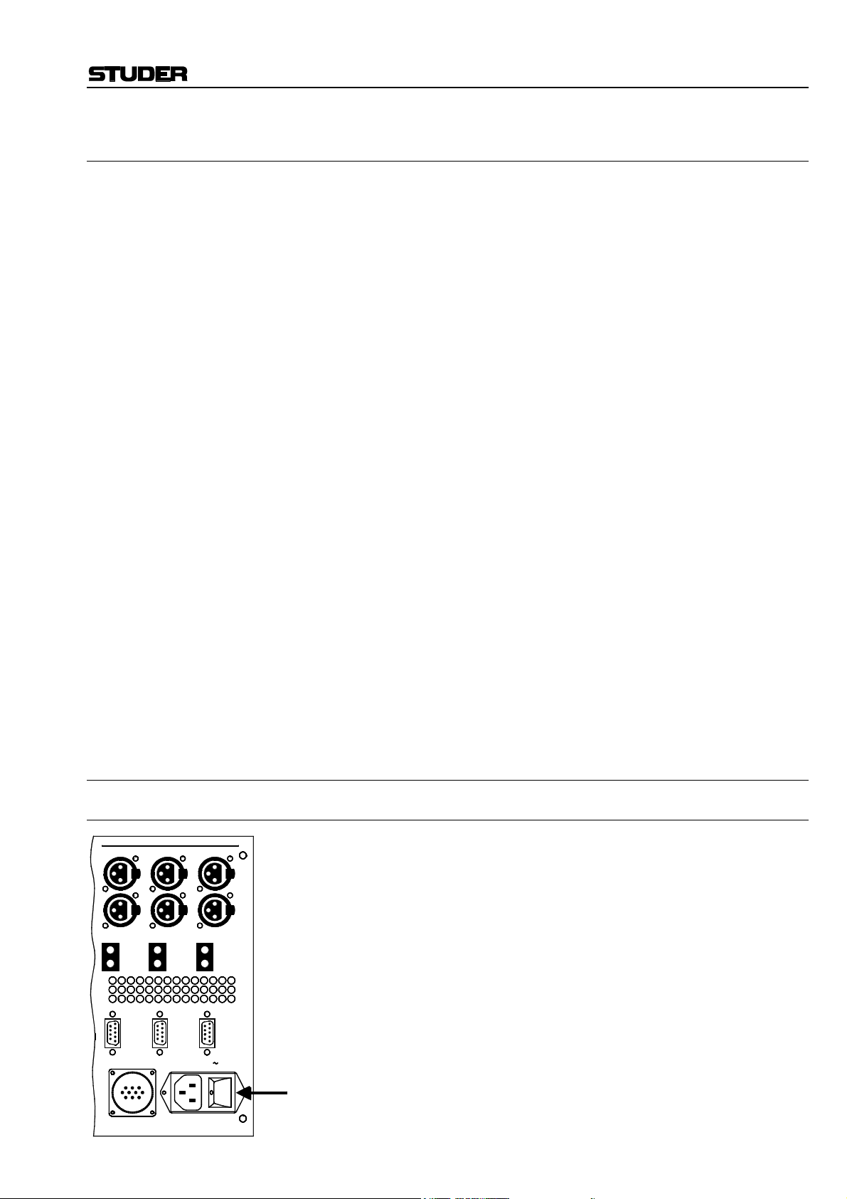
3 OPERATING CONCEPT
The normal operation of the console is as simple as possible. This has been
achieved by reducing the number of operating elements to the minimum.
Nevertheless, high flexibility has been achieved thanks to the use of touchscreen technology that just shows those operating elements needed at a
certain time.
A linear fader and some keys (ON, OFF, PFL, SEL, EQ, A, B) are the only
hardware operating elements within a fader strip. All other functions are
available through the touch-screen user interface. To maintain a good console overview, several LEDs are provided, together with four-character
channel label displays indicating the label for each channel. Pressing either
one of the SEL or EQ keys assigns the touch-screen to this function for
that specific channel. Parameters can now be entered via the four rotary
encoders (e.g. equalizer parameters), or directly through the assigned
touch-screen (e.g. EQ ON/OFF). This innovative user surface is called the
“Touch’n’action” concept and is patented by Studer.
In broadcast applications many DJs and operators without a special technical education work on the same mixing console. Every DJ has his preferred console settings, mainly EQ parameters for his microphone. In the
OnAir 1000, individual settings can be stored; by simply pressing a few
keys, every operator can recall his particular, tailor-made setting and concentrate afterwards upon his essential task – presenting a radio program
meeting the needs of the listeners.
Radio stations often use the same mixing console type for on-air and production. The “Snapshot” feature easily turns the production console into
an on-air console within seconds, if required.
Thanks to the integrated input channel router, the user/administrator can
place any input unit's signal to any fader strip on the console surface at his
convenience. Through a straightforward representation of the available
signals and faders on the screen, the input channel routing is easily done.
OnAir 1000 Digital Mixing Console
3.1 Operating Elements
3.1.1 Power Switch
MIC
A
2
3
1
B
2
3
1
INSERT
SEND
RETURN
CTRL
.
24V DC
INSERT
3
3
2
1
2
1
SEND
RETURN
CTRL
A
B
INSERT
100-240V
3
3
2
1
2
1
SEND
RETURN
CTRL
A
B
Date printed: 23.10.03 SW V 4.0 Operating Concept 3-1
For the two standard (single power supply) versions of the OnAir 1000
console, the mains power switch is located on the rear side of the console
next to the power inlet.
In case of DC operation of the console using an external power supply or a
battery, this power switch is without function; an external power switch
has to be foreseen by the installer. Please refer to chapter 14.1 for details
on DC operation.
Information on connection and operation of the two redundant power supply versions of the OnAir 1000 with their external power supply unit is
given in chapter 14.2.

OnAir 1000 Digital Mixing Console
3.1.2 Touch-Screen Unit
START
STOP
RESET
[1] [5] [2] [4] [3]
[1] Touch-Screen The touch-screen display is used for parameter entries; it normally displays
the current time and date in digital and analog formats, as well as the fader
and the user stopwatches.
[2] Rotary Encoders Depending on the current status, the rotary encoders are used for parameter
settings.
[3] Contrast Knob For setting the touch-screen display contrast, depending on the desired
viewing angle and the ambient light conditions.
[4] User Stopwatch Control Keys to control the user stopwatch (lower). Refer to chapter 5.13.
[5] Loudspeaker For PFL and talkback signals.
3-2 Operating Concept SW V 4.0 Date printed: 23.10.03

3.1.3 Metering Section
The OnAir 1000 mixing console is equipped with two dual 30-LED stereo
level meters and one correlator meter for each of the level meters.
–1 0 +1
12
6
0
6
12
18
24
PPM VU
3
2
1
0
1
2
3
5
7
10
20
–1 0 +1
12
6
0
dB
6
12
18
24
PPM VU
3
2
1
0
1
2
3
5
7
10
20
The meters can be set to simultaneously display either VU or PPM. Two
LEDs below the respective scale indicate the selected mode (for mode setting, please refer to the OnAir 1000 Service Manual).
It is configurable for both meters which signal they display; the following
sources can be selected in the configuration menu:
For configuration details refer to chapter 11.2.4.
OnAir 1000 Digital Mixing Console
Meter 1 Meter 2 Source
X X CR MONITOR
X X PROGRAM
X X RECORD
X X AUX 1
X X AUX 2
X AUDIT
X N–1 A
POWER ALARM
Below the meters an electret talkback microphone is integrated into the
console that can be used as a talkback source. If desired, an external talkback microphone can be connected to the rear of the console (for details,
refer to chapters 14.6 and 15.2).
If the console is powered by the mains voltage and an additional 24 V
DC
supply is used for redundancy, or if the (optional) redundant power supply
is used, the red POWER ALARM LED indicates a failure of one of the
power supplies, allowing for timely repair without interruption of the continuity program.
Date printed: 23.10.03 SW V 4.0 Operating Concept 3-3

OnAir 1000 Digital Mixing Console
3.1.4 Monitoring and Talkback Section
[1] [6]
[1] Control Room (CR) Monitoring Selector
Ten mutually releasing keys for selecting the control room monitoring
signal from the following sources:
AUX 2/AUX 1: Auxiliary, general purpose outputs;
AUDIT: Auxiliary, general purpose output with configurable inputs;
Σ REC: Recorder output;
Σ PGM: Program (on-air) output;
PFL: PFL (pre-fader listening);
EXT 3: External analog input signal;
EXT 2: External analog input signal;
EXT 1: External analog input signal;
OFF AIR: External analog input signal (e.g. tuner for off-air listening).
ON-AIR CR-MIC STUDIO-MIC
AUX 2
AUX 1
AUDIT
REC
PGM
DIM
CUT
4
5
3
2
1
0
MON PFL / TB TALK BACKPHONES
PFL
EXT 3
EXT 2
EXT 1
OFF AIR
EXT
PFL
PFL
MON
4
6
9
5
3
7
2
8
1
0
PFL
MON
PFL
MON
4
6
9
5
3
7
2
8
1
0
[7]
F 5
F 4
F 3
F 2
F 1
N–1 B
N–1 A
AUX 2
AUX 1
6
7
STUDIO
8
9
[5] [4] [3] [2]
[2] CR Monitor Speaker Control
MON : Monitoring volume control.
DIM: If pressed, the monitor speaker level is reduced by 20 dB.
The DIM function is activated automatically if one of the TALK BACK
keys is pressed. If “CR DIM WHEN AUDITION SEL” is set in the
COMMON SETTINGS page (details: refer to chapter 11.2.2), the monitoring source is AUDIT, and the DJ microphone is on, the AUDIT level is
not muted but reduced by 20 dB.
If DIM is active, the DIM key is illuminated.
CUT: If pressed, the monitor speakers are muted, and the CUT key is illumi-
nated. As long as one of the CR or DJ microphones is on, the monitor
speakers are automatically muted, and the CUT key is illuminated.
3-4 Operating Concept SW V 4.0 Date printed: 23.10.03

OnAir 1000 Digital Mixing Console
[3] PFL/TB PFL/TB: Volume control for the built-in PFL/TB speaker.
EXT PFL: The EXT PFL input can be used as an external PFL input to the monitor-
ing unit. If pressed, the key is illuminated, the external signal is routed to
the PFL output, and the external PFL control output is active.
PFL>MON: If PFL is active on any channel, the PFL signal is routed to the main
monitor speakers. If no PFL is selected, the monitoring signal is the stereo
CR signal as selected. The PFL>MON key is illuminated if active.
[4] Headphones PHONES : Headphones volume control. The headphones socket (6.3 mm TRS jack) is
located below the hand rest on the left side of the console.
Three keys allow different monitoring modes:
PFL: PFL and TB signals are routed to the headphones.
MON/PFL: The left-channel headphones signal is the mono PFL signal, while the
right-channel headphones signal is the mono CR signal as selected by the
monitoring source selector [1]. If no PFL is selected, the headphones signal is the stereo CR signal as selected.
MON: The headphones signal is the same stereo signal as selected by the moni-
toring source selector [1]. It is, however, not affected by the DIM and CUT
functions.
[5] Talkback Selector for five talkback destinations:
N–1 B/N–1 A: Connection between the talkback microphone* in the control room and the
corresponding clean-feed (N–1) output; this allows talking e.g. to the connected telephone hybrid(s) or communication lines.
AUX 2/AUX 1: Connection between the talkback microphone* in the control room and the
AUX 2 or AUX 1 outputs.
STUDIO: Connection between the talkback microphone* in the control room and the
studio speakers and headphones.
The built-in PFL/TB loudspeaker and/or the headphones are used for talkback listening in the control room.
* If a console is equipped with an external talkback microphone, this micro-
phone is used instead of the integrated talkback microphone.
[6] F1 to F5 Spare keys for future functions.
[7] Signaling Lamps ON-AIR Is turned on by a control signal on the “SIGN.” control connector on the
monitoring part of the connector panel.
CR-MIC Is on if at least one microphone in the control room is routed to the pro-
gram or to the record output (i.e. the corresponding output is selected, the
input channel is ON, the input channel fader and the master fader are
opened).
STUDIO-MIC Is on if at least one microphone in the studio is routed to the program or to
the record output (i.e. the corresponding output is selected, the input channel is ON, the input channel fader and the master fader are opened).
Date printed: 23.10.03 SW V 4.0 Operating Concept 3-5
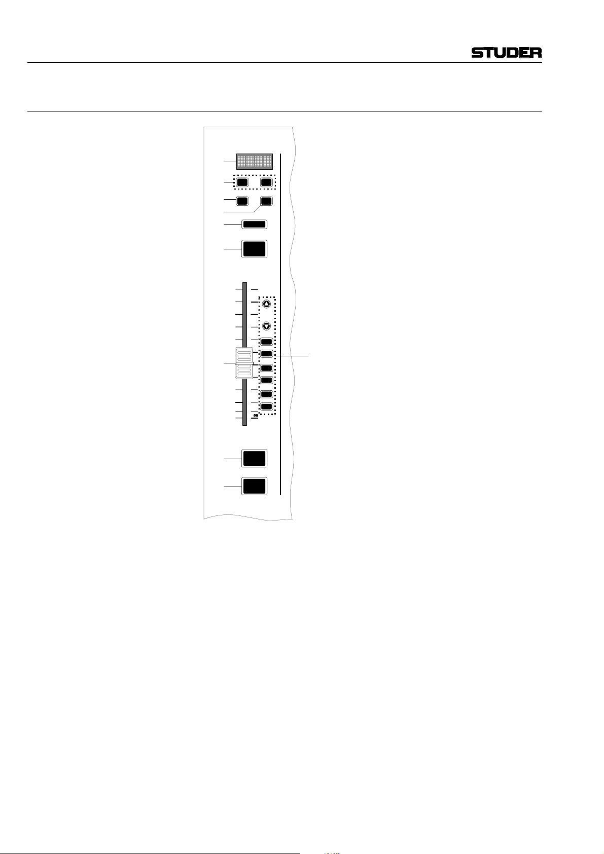
OnAir 1000 Digital Mixing Console
3.1.5 Fader Section
[1]
[9]
[7]
[8]
[6]
A B
SEL EQ
OVL
[5]
[4]
[3]
[2]
PFL
10
0
10
20
30
40
50
60
ON
OFF
AUTO
TAKE
OVER
PGM
REC
AUX1
AUX2
INS1
INS2
[10]
[1] Channel Label Display Four-character display, indicating the label of the input channel momen-
tarily selected. The channel label can be set in the INPUT CONFIG. page;
refer to chapter 11.2.1. When pressing the A or B key, the label will scroll
by in full length.
[2] OFF (“key no. 3”) Keys for deactivating or activating an input channel. Can be reconfigured.
[3] ON (“key no. 2”) For details please refer to chapters 8 and 14.3.
[4] Linear Fader The audio path is fully digital, therefore the signal does not pass through
the fader; stroke length is 100 mm. For details concerning fader start control please refer to chapters 8 and 14.3.
[5] PFL (“key no. 1”) Key for activating/deactivating the PFL (pre-fader listening) function.
[6] OVL Channel overload indicator.
3-6 Operating Concept SW V 4.0 Date printed: 23.10.03

OnAir 1000 Digital Mixing Console
[7] SEL Multi-function key:
• For activating the Channel Control page on the touch-screen for this
respective input channel. For details please refer to chapters 4.4 and
4.5.
• If the INPUT CONFIG. page is already displayed on the central touch-
screen, pressing the SEL key in a fader strip selects the corresponding
input channel for configuration.
• If the Mixer Setup page (SNAPSHOTS/MIC SETTING) is already
displayed on the central touch-screen, pressing the SEL key in a microphone input fader strip selects the corresponding input channel for
configuration.
[8] EQ For activating the EQ/filter page on the touch-screen for this respective
input channel. For details please refer to chapters 4.6 and 4.7.
[9] A, B For selecting the physical inputs A or B of this input unit. Each time one of
these keys is pressed (even if this physical input is currently active), the
full-length label scrolls by in the four-character channel label display.
[10] LEDs AUTO TAKEOVER Up/Down Arrow LEDs. After having modified the channel routing or
during radio automation (CAB) operation, they indicate that the fader has
to be moved upward/downward to match the physical and the logical positions.
PGM LED indicating that this input channel signal is routed to the Program out-
put.
REC LED indicating that this input channel signal is routed to the Record out-
put.
AUX1 LED indicating that this input channel signal is routed to the AUX1 out-
put.
AUX2 LED indicating that this input channel signal is routed to the AUX 2 out-
put.
INS1 LED indicating that this input channel signal is routed over the analog
insert 1.
INS2 LED indicating that this input channel signal is routed over the analog
insert 2.
Date printed: 23.10.03 SW V 4.0 Operating Concept 3-7

OnAir 1000 Digital Mixing Console
3.2 Connector Panels
Analog-biased
(left) and
digitally-biased
(right)
versions
MIC
LINE
DIGITAL
CR
TB MIC
STUDIO
INSERT
DIGITAL OUT
ANALOG OUT
MONITORING
A
B
1 2
1 2
SEND
3
3
A
B
1 2
3
3
B
A
1 2
3
3
L
A
1 2
3
3
L
A
1 2
3
3
L
A
1 2
3
3
L
A
1 2
3
3
L
A
1 2
3
3
A
B
1 2
3
3
A
B
1 2
3
3
IN
OUT
1
1 2
3
3
3
IN
OUT
1
1 2
3
3
3
2
RETURN
INSERT
1 2
SEND
RETURN
INSERT
1 2
SEND
RETURN
INSERT
R
L
B
1 2
1 2
R
1 2
R
1 2
R
1 2
R
1 2
1 2
1 2
2
1 2
2
1 2
3
3
L
B
1 2
3
3
L
B
1 2
3
3
L
B
1 2
3
3
L
B
1 2
3
3
B
A
A
B
A
A
MIC GAIN
OUTPUT LEVEL
MIC GAIN
OUTPUT LEVEL
1
CTRL
100-240V
CTRL
24V DC
CTRL
R
1 2
CTRL
RS232
R
1 2
CTRL
R
1 2
R
1 2
R
1 2
B
B
TIME SYNC
CTRL
RS422 AFNOR
CTRL
UNIT
MUST BE
EARTHED!
CTRL
IN
VIDEO
CTRL
CTRL
WCLK
OUTPUT
CLOCK SYNC
CTRL
WCLK
INPUT
INPUT
AES SYNC
1
CTRL
3
2
TEL B
PGM
1
1
2
3
3
AUX1
1
1
2
3
3
L
PGM
1
1
2
3
3
L
AUX1
1
1
2
3
3
N–1A
1
1
2
3
3
MON
CTRL
STUDIO
CR
L
OUT
2
A
A
REC
1
1
2
1
2
R
L
1
2
R
L
1
2
2
2
3
3
AUX2
1
2
2
3
3
R
REC
1
2
2
3
3
R
AUX2
1
2
2
3
3
TEL HYBRID
TEL A
N–1B
1
1
2
R
13231
3
2
B
B
2
3
PFL
EXT
CTRL
GUEST
STUDIO MONITOR (AUDIO)
EXTERNAL MONITOR INPUT
RS232
SIGN
SERIAL IF
CTRL
RS422
C
C
MIC
LINE
DIGITAL
CR
TB MIC
STUDIO
INSERT
DIGITAL OUT
ANALOG OUT
MONITORING
A
1 2
3
A
1 2
3
A
1 2
3
L
1 2
3
L
1 2
3
A
1 2
3
A
1 2
3
A
1 2
3
A
1 2
3
A
1 2
3
IN
1 2
3
IN
1 2
3
132
1
2
3
L
13231
L
1
2
3
13231
L
3
1
2
B
1 2
SEND
3
B
3
B
3
A
3
A
3
RETURN
INSERT
1 2
SEND
RETURN
INSERT
1 2
SEND
RETURN
INSERT
R
L
B
1 2
1 2
3
3
R
L
B
1 2
1 2
3
3
CTRL
100-240V
CTRL
24V DC
CTRL
R
1 2
CTRL
RS232
R
1 2
CTRL
TIME SYNC
B
B
1 2
3
B
1 2
3
B
1 2
3
B
1 2
3
B
1 2
3
A
A
B
A
A
B
A
A
B
A
A
B
A
A
OUT
1
2
1 2
3
3
MIC GAIN
OUTPUT LEVEL
OUT
1
1 2
2
3
3
MIC GAIN
OUTPUT LEVEL
2
1
CTRL
B
RS422 AFNOR
CTRL
B
B
B
B
UNIT
MUST BE
EARTHED!
CTRL
IN
VIDEO
CTRL
CTRL
WCLK
OUTPUT
CLOCK SYNC
CTRL
WCLK
INPUT
INPUT
AES SYNC
1
CTRL
3
2
TEL B
PGM
132
AUX1
1
2
3
PGM
2
AUX1
1
2
3
N–1A
2
MON
CTRL
STUDIO
CR
OUT
3
1
2
A
A
REC
1
1
1
R
L
1
R
L
1
2
2
3
3
AUX2
1
2
2
3
3
R
REC
1
2
2
3
3
R
AUX2
1
2
2
3
3
TEL HYBRID
TEL A
N–1B
1
3
2
B
B
2
3
PFL
EXT
CTRL
GUEST
STUDIO MONITOR (AUDIO)
EXTERNAL MONITOR INPUT
RS232
SIGN
SERIAL IF
CTRL
RS422
C
C
1
R
3-8 Operating Concept SW V 4.0 Date printed: 23.10.03

OnAir 1000 Digital Mixing Console
4 CHANNEL FUNCTIONS
The OnAir 1000 has ten input channel faders and two master faders on the
surface. The input channel fader strips consist of a four-character channel
label display, two input selector keys, a SEL key, an EQ key, an OVL
overload indication, a PFL key, the fader, an ON and an OFF key. All keys
are equipped with LED indicators. Six LEDs (PGM, REC, AUX1, AUX2,
INS1, INS2) display the signal routing of this respective input channel. If
the console is remote-controlled by a radio automation system (CAB), the
two AUTO TAKEOVER arrow LEDs indicate in which direction the fader
has to be moved in order to match the physical and the logical position of
the fader.
Input Router: Through the integrated input router, the output signal of every individual
input unit can be assigned to any input fader strip on the console surface
(see chapter 5.8). The input channel parameters relate to the input unit and
not to the fader strip. They will be re-routed when the input unit is assigned to another fader. Exception: The position of the two master faders
is fixed and cannot be re-routed.
Access Permission: In the following chapters we assume that the user has access permission to
all functions, unless otherwise noted. Access permission may be limited to
some users by the administrator, causing that certain screen parts are hidden. Full access permission is in such a case only obtained when entering a
password. For a description of how to set up the access permission, refer to
chapter 10.
4.1 Keys
Channel Functions: The channel key functions are configurable; this configuration is valid for
Configuration Key 1 (“PFL”) Key 2 (“ON”) Key 3 (“OFF”)
For details on the key configuration refer to chapter 8.
A/B Input Keys: For microphone, analog line, and digital input units, the input keys A and
If the input channel is connected to an automation system, scrolling of the
SEL Key: By pressing one of the SEL (select) keys, the Channel Control page is
PFL
ON
OFF
A B
SEL
the whole console (and not per input channel). The different configuration
possibilities are:
1 (Default)
2
3
4
PFL ON OFF
PFL ON/OFF LOCATE
PFL ON LOCATE
PFL ON/OFF NEXT
B directly select one of the two physical input signals. The selected input
is indicated by an LED integrated in the respective key, and the source
name appears in the channel label display. If the input channel is active
(i.e. input channel ON, fader open, and output selected), the input selection
is disabled.
channel label display indicates that this input channel is “ON AIR”. For
more details on this topic, please refer to chapter 9.
opened on the touch-screen. Parameters for this input channel can now
easily be entered with the four rotary encoders and the touch-screen fields.
The SEL key of the corresponding fader strip is illuminated.
Date printed: 23.10.03 SW V 4.0 Channel Functions 4-1

OnAir 1000 Digital Mixing Console
EQ Key: The EQ key opens the EQ/filter page on the touch-screen, and the corre-
EQ
sponding SEL key is illuminated, indicating that parameters of this input
channel are displayed.
The EQ key is illuminated if the equalizer is on.
By observing if the EQ keys are illuminated, it can be determined at a
glance in which input channels the equalizer settings are active.
4.2 Faders
Since the audio path is fully digital, the signal does not pass through the
faders. Therefore, linear-track mono faders are used. The stroke length is
100 mm. When opening the fader, fader start or signaling commands can
be released, depending on the configuration (refer to chapter 8).
Master Faders: On the right-hand side of the input channel faders, a master fader for each
the program and the record output is provided (refer to chapter 5.14).
These two master faders can be enabled or disabled at the user’s convenience.
4.3 LED Indicators
In each fader strip, LEDs display the actual routing of the signals. The
selected physical input being (either A or B) is indicated by the illuminated A or B selector key, and the filtering of the signal by the equalizer
function is indicated by the illuminated EQ key.
With all these displays, the operator has an immediate overview of the
Channel Label Display: The four-character channel label display shows the name of the selected
OVL (Overload): A red OVL indicator per fader strip signalizes an overload condition any-
Signals in the OnAir 1000 are processed with sufficient digital headroom
Overload in an input channel is indicated if the signal level reaches 0 dB
PGM / REC: The PGM and/or REC LEDs are on if the respective input channel's signal
AUX1 / AUX2: The AUX1 and AUX2 LEDs are on if the respective input channel's signal
OVL
PGM
REC
AUX1
AUX2
major console settings at a single glance.
physical input. The channel label is entered in the Mixer Setup menu of
the INPUT CONFIG. page, using a soft keyboard appearing on the touchscreen.
where within the corresponding input channel’s signal processing path.
through the entire signal processing chain. Besides, most outputs (PGM,
REC, AUX1, AUX2, INSERT SEND1/2) are equipped with limiters in order to prevent overloads. All limiters are set to 0 dBFS with fixed attack
and release times.
FS
Due to the output limiters, normally distortions will be avoided even in
case of an overload.
is routed to the PGM and/or the REC output(s). The output routing can be
changed in the Channel Control page on the touch-screen that is opened by
pressing the SEL key. The “ΣPROGRAM” and/or “ΣRECORD” touch-
screen fields are highlighted if selected.
is routed to the AUX output(s). The AUX settings can be changed in the
Channel Control page on the touch-screen that is opened by pressing the
SEL key. There, both auxiliaries can be independently set as “AF” (after-
.
4-2 Channel Functions SW V 4.0 Date printed: 23.10.03

OnAir 1000 Digital Mixing Console
fader), “PF” (pre-fader), “ON” or “OFF”. These touch-screen fields are
INS1 / INS2: The INS1 or the INS2 LED is on if the respective input channel's signal is
INS1
INS2
AUTO TAKEOVER Arrow LEDs: After having modified the channel routing or during radio automation
AUTO
If the console is used together with an automation system, the fader value
TAKE
OVER
If an input channel is currently on air, its label continuously scrolls by in
highlighted if selected.
routed trough one of the analog inserts 1 or 2. The inserts are controlled in
the AUX MASTER/INSERTS page on the touch-screen.
(CAB) operation, they indicate that the fader has to be moved upward/downward to match the physical and the logical positions.
can be set by the automation system via the “Monitora” protocol. In case
the user would like to take-over the control of the signal with the fader, the
AUTO TAKEOVER arrow LED(s) of the input channels being controlled
by the automation system indicate in which direction the fader has to be
moved to match its physical and its logical position. If the positions are
matched, or if, by chance, the fader is in the exact position, both arrow
LEDs remain illuminated as long as this input channel is on air.
the channel label display.
AUTO
TAKE
OVER
Channels not con-
trolled by a CAB
system
AUTO
TAKE
OVER
Audio level above
the fader position –
move fader down
AUTO
TAKE
OVER
Audio level below
the fader position –
move fader up
AUTO
TAKE
OVER
Audio level
equal to the
fader position
Date printed: 23.10.03 SW V 4.0 Channel Functions 4-3
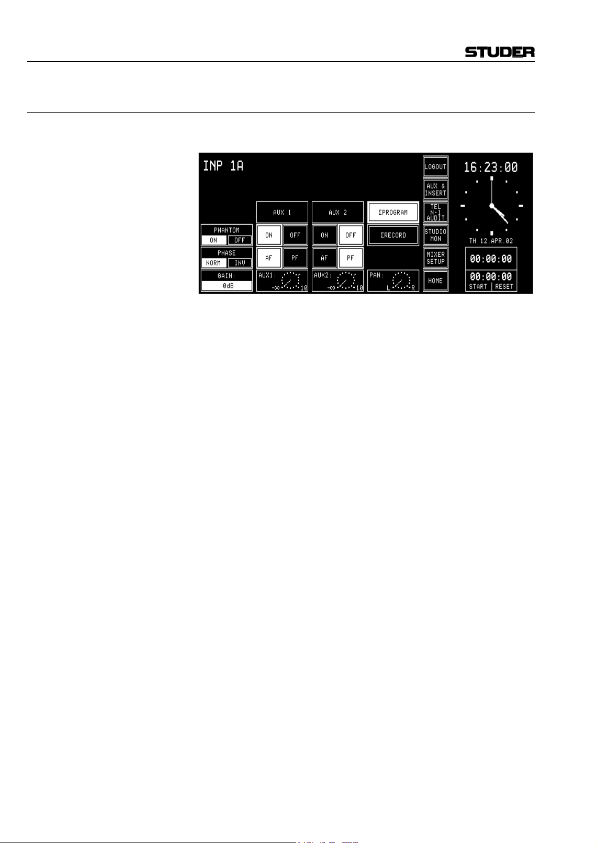
OnAir 1000 Digital Mixing Console
4.4 Channel Control Page, Microphone Input
The Channel Control page for a microphone input channel is opened by
pressing the SEL key of a mic channel's fader strip.
PHANTOM Touching the “ON” part of the PHANTOM field turns the 48 V phantom
power on; a touch on the “OFF” part of the field turns it off again. The
status is indicated by highlighting the corresponding field.
PHASE The phase of the microphone signal is inverted by touching the “INV” part
of the PHASE touch-screen field; “INV” is highlighted. Touching
“NORM” de-activates the phase inversion.
GAIN The microphone preamp's gain is set with the first rotary encoder (in a
–5...+75 dB range); the adjusted value is indicated in the GAIN field.
AUX 1 / AUX 2 The AUX 1/2 ON and OFF touch-screen fields route the input channel
signal to the corresponding auxiliary bus, if “ON” is selected (and highlighted).
The AF/PF touch-screen fields allow selection whether the signal is taken
after- (AF) or pre-fader (PF). The current selections are highlighted.
The AUX levels (–∞ to +10 dB; 0 dB position is marked with a dash) are
adjusted with the second and third rotary encoder. The settings are graphically displayed in the fields right above the rotary encoders.
The output routing of this particular input channel is performed with the
“ΣPROGRAM” and “ΣRECORD” touch-screen fields.
PAN The fourth rotary encoder positions the source within the stereo image, the
PAN (-ning) indicator shows the adjusted position.
4-4 Channel Functions SW V 4.0 Date printed: 23.10.03

4.5 Channel Control Page, Line Input
The Channel Control page for a line input channel is opened by pressing
the SEL key of a digital or an analog line input channel's fader strip.
MODE Line level inputs have a MODE field defining whether the input is proc-
essed in “ST”(-ereo) or in “MONO” mode. In mono mode the stereo input
signal from the input unit is added to a mono signal and attenuated by
3 dB.
Stereo signals are processed in the following modes:
LR: Normal stereo mode;
RL: Left/right stereo channels swapped;
LL: Left signal on both stereo channels;
RR: Right signal on both stereo channels.
OnAir 1000 Digital Mixing Console
PHASE The phase (of the left input path only) is inverted by touching the “INV”
part of the PHASE touch-screen field; “INV” is highlighted. Touching
“NORM” de-activates the phase inversion. Only in the “RR” case, the
phase inversion takes place in the R input path.
CAL In the CAL field, the gain deviation referred to nominal level setting is dis-
played; max. deviation: ±15 dB, adjustment with the first rotary encoder.
AUX 1 / AUX 2 The AUX 1/2 “ON” and “OFF” touch-screen fields route the input channel
signal to the corresponding auxiliary bus, if “ON” is selected (and highlighted).
The “AF” / “PF” touch-screen fields allow selection whether the signal is
tapped after- (AF) or pre-fader (PF). The current selections are highlighted.
The AUX levels (–∞ to +10 dB; 0 dB position is marked with a dash) are
adjusted with the second and third rotary encoder. The settings are graphically displayed in the fields right above the rotary encoders.
The bus assignment is performed with the “ΣPROGRAM” and “ΣREC-
ORD” touch-screen fields.
BAL The fourth rotary encoder adjusts the position of the stereo image, the
BAL indicator shows the adjusted position.
Date printed: 23.10.03 SW V 4.0 Channel Functions 4-5

OnAir 1000 Digital Mixing Console
Access Permission: Depending on the access permission (see chapter 10) of the user currently
logged in, the functions not available to this user will not be displayed on
the Channel Control page; an example is given below. This user cannot access the following parameters:
• PHASE
• AUX 1
• Output summing buses (ΣPROGRAM, ΣRECORD)
• PAN/BAL.
If the user has no access permission at all, the Channel Control page will
not be displayed.
4-6 Channel Functions SW V 4.0 Date printed: 23.10.03

4.6 EQ/Filter Page, Microphone Input
The EQ/filter page for a microphone input channel is opened by pressing
the EQ key of a microphone input channel's fader strip. If the user has no
access permission to the EQ and filter parameters, the EQ/filter page will
not be displayed.
HPF The HPF “ON” / “OFF” touch-screen field is a high-pass filter switch. The
filter is part of the analog front end and is available on microphone input
channels only. “ON” is highlighted if the filter is active.
OnAir 1000 Digital Mixing Console
EQ The EQ “ON” / “OFF” touch-screen fields activate or bypass the equalizer.
If the equalizer is active (i.e. “ON”), the EQ key will be illuminated. If the
EQ is bypassed (i.e. “OFF”), the preset frequency curve is displayed on the
touch-screen nevertheless.
The four rotary encoders are the control elements for the equalizer. The
low-frequency section is a shelving-type filter with two selectable turnover
frequencies and variable boost/cut. The frequency is selected by the lefthand “CUTOFF” touch-screen fields, the gain is set with the first (leftmost) rotary encoder. The second rotary encoder sets the frequency of the
mid-frequency section which is a peaking-type filter. The third rotary encoder controls the mid-frequency boost/cut. The fourth (rightmost) rotary
encoder controls the gain of the high-frequency section which again is a
shelving-type filter with two selectable turnover frequencies. The righthand “CUTOFF” touch-screen fields allow frequency selection of the
high-frequency shelving filter.
Note: The HF cutoff frequencies can be reduced by approx. one octave (resulting
in an increased filter effect) when activating Customer Code 0x00000002;
refer to chapter 11.2.11.
EQ Specs:
Filter Mode Frequency Gain range Comment
High-pass filter HPF –3 dB @ 80 Hz ON/OFF
EQ low-frequency Shelving 200 Hz/400 Hz
EQ mid-frequency Peaking
EQ high-frequency Shelving 5 kHz/10 kHz
200 Hz...10 kHz,
1/6 octave steps
–15 dB...+15 dB,
1 dB steps
–15 dB...+15 dB,
1 dB steps
–15 dB...+15 dB,
1 dB steps
Analog, 12 dB/oct.,
mic input ch only
-
Q = 0.7
see Customer
Code (11.2.11)
Date printed: 23.10.03 SW V 4.0 Channel Functions 4-7

OnAir 1000 Digital Mixing Console
4.7 EQ/Filter Page, Analog Line/Digital Input
The EQ/filter page for a line input channel is opened by pressing the EQ
key of an analog or digital line input channel's fader strip. If the user has
no access permission to the EQ parameters, the EQ/filter page will not be
displayed at all.
The only difference between the analog line/digital and the microphone
EQ/Filter pages is the missing HPF high-pass filter switch on analog
line/digital input channels.
4-8 Channel Functions SW V 4.0 Date printed: 23.10.03

5 MASTER FUNCTIONS
Master functions are not input channel-related but global functions. These
are audio functions (AUX master level, studio monitoring), non-audio
functions (telephone hybrid control, clock, stopwatch), snapshot management, and system configuration.
Touching one of the LOGIN, AUX & INSERT, TEL, STUDIO MON,
MIXER SETUP, or HOME–CHN ON/OFF fields will always lead to the
corresponding page.
5.1 Login/Logout
The console always starts up in default user mode. If the user wants to
work in his own environment, he must log-in. He has to touch the LOGIN
field on the touch-screen. The LOGIN page will appear where the user can
touch the field with his own name.
OnAir 1000 Digital Mixing Console
More information on the login procedure can be found in chapter 10.5.
After having logged in, the LOGIN field changes to LOGOUT; when the
user leaves the console, this field must be used. After having touched
LOGOUT, a dialog box appears, asking for confirmation. This is used as a
protection against logging out inadvertently.
If a console is operated by one person only, the system administrator simply can enable all access rights for the default user. This is the way the
user can control all console functions (except the administration functions)
without having to log-in. A default user is always defined in the User ad-
Date printed: 23.10.03 SW V 4.0 Master Functions 5-1

OnAir 1000 Digital Mixing Console
ministration table, his name is DEFAULT USER. The access permissions
of this user can be edited. His record cannot, however, be deleted, and no
password can be defined for him.
5.2 AUX and Insert Control
The AUX MASTER/INSERTS page is entered by touching the AUX &
INSERT field on the touch-screen.
If the user has no access permission for the AUX and/or insert parameters,
there will appear a text next to AUX MASTER and/or INSERTS, telling
the user that he cannot modify the parameters.
AUX MASTER: The two rotary encoders below the AUX 1 and AUX 2 gain indication
symbols are used to adjust the desired level of the corresponding AUX
master. The gain can be adjusted in a range of –∞ to +10 dB; the 0 dB po-
sition is marked with a dash.
ON/OFF selection of the AUX master buses is done by touching the corresponding fields on the screen. A highlighted background indicates the current status.
The AUX 1 and AUX 2 gain indication symbols are always displayed,
even if no output unit is jumper-configured for AUX 1 and/or AUX 2.
INSERTS: On the same page, the insert points can be assigned. Assignment is possi-
ble to any of the following signals:
• CH1 to CH10,
• PROGRAM bus,
• RECORD bus,
• Talkback to Studio output,
• Talkback to Control Room (CR) output,
• NONE.
A signal can only be assigned to an insert while the insert is set to OFF, by
touching the channel/bus label field of the insert box. The label field is
highlighted. Then it can be changed with the rightmost rotary encoder. If
the insert is set to ON, the channel/bus label field cannot be highlighted,
and the insert assignment cannot be changed.
The insert send always follows the setting as displayed on the screen; it
remains active while the insert is switched OFF. If the insert is switched
ON, a switchover from the internal connection to the insert return is performed.
5-2 Master Functions SW V 4.0 Date printed: 23.10.03

OnAir 1000 Digital Mixing Console
Each signal can be assigned to one insert only. If a signal is already assigned to an insert, it will not appear in the channel/bus label field during
signal selection for another insert.
The insert is assigned per input unit and not per physical input, which
means that the insert assignment is always valid for both physical inputs A
and B of an input channel.
The insert assignment and the insert ON/OFF setting are included in snapshots.
The insert assignment is displayed in the corresponding fader strip by an
illuminated INS LED for as long as the insert is active (ON).
5.3 N–1/Audition Bus and Telephone Hybrid Control
Two clean-feeds (N–1A, N–1B) are provided. The clean-feeds can be used
as mono outputs to telephone hybrids, or as mono line outputs. The audition bus can either be used as a special stereo monitoring bus (for information on the special CUT and DIM conditions, please refer to chapter
11.2.2, “CR DIM WHEN AUDITION SELECTED”), or as a third, mono
or stereo clean-feed.
If the user has no access permission for the clean-feed and/or audition bus
parameters, there will appear a text next to the corresponding field, telling
the user that he cannot modify the parameters.
The clean-feeds as well as the audition bus have master level controls that
can be accessed on the N–1/audition master and telephone hybrid page
(opened by touching the TEL/N–1/AUDIT field). The output levels are
controlled with the rotary encoders; the output gain range is –∞ to +10 dB,
the 0 dB position is marked with a dash.
Two telephone hybrid interfaces to which the clean-feeds are fed can be
controlled by the ON-AIR, HOLD, and TELEPHONE fields on this page.
TELEPHONE switches the telephone line to the telephone. By touching
HOLD, the telephone line is routed to the telephone hybrid interface. The
return signal is connected, but the incoming signal is not fed to the console. Only when touching ON-AIR, both the incoming and the return signals are connected to the console.
Date printed: 23.10.03 SW V 4.0 Master Functions 5-3

OnAir 1000 Digital Mixing Console
5.3.1 N–1 and Audition Bus Routing
For bus routing, first open the INPUT CONFIG. page of the desired input
channel (the example above shows the INPUT CONFIG. page of a digital
input channel; for a mic input channel, the INPUT CONNECTOR field is
not displayed, and for an analog line input channel, there will be the
LEVEL and HEADROOM fields displayed instead).
When touching the BUS ASSIGNMENT field on this page, it changes as
follows, allowing to select the N–1 A/B and audition bus routing:
In the TO N–1 A, TO N–1 B, and TO AUDIT fields, the input signal is
routed to the N–1A, N–1B, or audition bus, with the options given in the
table below.
Setting Meaning
NEVER The input channel is never routed to N–1 or AUDIT
WHEN PG/REC
WHEN PRG
WHEN REC
ALWAYS
The input channel is routed to N–1 and/or AUDIT if the input channel is
either assigned to the program or to the record bus
The input channel is routed to N–1 and/or AUDIT if the input channel is
assigned to the program bus
The input channel is routed to N–1 and/or AUDIT if the input channel is
assigned to the record bus
The input channel is always routed to N–1 and/or AUDIT, regardless of
the bus assignment
The audition bus is similar to the N–1 buses, but it is a stereo bus that can
be selected as a monitoring source in the control room.
Once the bus routing is completed, return to the INPUT CONFIG. page by
touching the BACK TO CTRL OUT/IN CFG. field.
The N–1 A/B and the audition output levels are set using the rotary encoders on the TEL/N–1/AUDIT page, as described in chapter 5.3 above.
5-4 Master Functions SW V 4.0 Date printed: 23.10.03

5.4 Studio Monitoring
The STUDIO MONITORING SOURCE page is opened by touching the
STUDIO MON field. This page allows selecting one of six signals to be
routed to the studio monitoring loudspeakers and headphones. This selection can also be done via a pushbutton remote control from the studio (optional accessory “Studio Talkback Box” available). The field of the currently selected signal source is highlighted.
The signal selected with the EXT3 field is the same as the one selected
with EXT3 on the CR monitor selector on the right hand side of the console; this signal is fed to the console via the 15-pin EXTERN MONITOR
INPUT (B) connector at the rear of the console.
OnAir 1000 Digital Mixing Console
For a more detailed description of the monitoring system, see chapter 6.
Date printed: 23.10.03 SW V 4.0 Master Functions 5-5

OnAir 1000 Digital Mixing Console
5.5 Mixer Setup
The Mixer Setup page (SNAPSHOTS/MIC SET/CHAN ROUT) gives
access to several function groups used for setting the general status of the
console. These are: Global snapshots, private snapshots, global microphone (mic) settings, private microphone settings, global channel routings.
At the left of the Mixer Setup page there is the SNAPSHOTS area. The
five fields allow snapshot selection.
Up to ten mic settings can be selected in the MIC SET area; either all of
them are displayed, or – if the CHAN ROUT section is visible on this page
as well – they are displayed in groups of four and can be browsed using the
NEXT... and/or PREV... fields, as shown above.
Five global channel routings are accessible in the CHAN ROUT area. If no
global channel routings should have been defined by the system administrator, the CHAN ROUT area is not displayed, as shown below.
The right part of the Mixer Setup page also provides the following command fields:
PRIVATE/GLOBAL: Users can select between private and global snapshots and mic settings.
SYSTEM CONFIG: This field leads to the second level of mixer setup functions. These are
accessible only for users having the corresponding access right set in the
user configuration. A new page is displayed, allowing to select from several groups of configuration parameters.
ROUTING: This field leads to the CHANNEL ROUTING. page. This page is only
accessible for users having the corresponding access right set in the user
configuration.
The use of snapshots, mic settings, and channel routings is described in the
following chapters, followed by some information on user administration
and the watch/stopwatch functions.
5-6 Master Functions SW V 4.0 Date printed: 23.10.03

5.6 Snapshots
A snapshot is a copy of a momentary console setup. It contains all parameters (as input selection, input gain, phase, phantom power, balance or
panorama setting, EQ settings, AUX settings, input channel ON/OFF, and
insert assignment), except fader positions and PFL. A snapshot does not
contain any parameters being part of the console configuration (input
channel routing, channel labels, control signal functions, clean-feed bus
assignment, level meter assignment, etc.).
Each user having a personal password can save up to four private snapshots (max. 20 users), and up to five global snapshots (available for every
user) can be saved in the console's flash memory. More snapshots can be
saved on a PC-Card (refer to chapter 5.9) and loaded from the card into the
console's flash memory if required.
A name can be given to every snapshot which is displayed in the leftmost
field column.
5.6.1 Recall a Snapshot from Memory
OnAir 1000 Digital Mixing Console
Select a snapshot by touching one of the name fields. The name of the
selected snapshot is highlighted. When touching the RECALL FROM
MEMORY field, the snapshot will immediately be recalled from the console's internal flash memory, except if the current input channel is active
(switched to the program or the record bus); then the recall operation is
delayed until the input channel is closed.
During execution of the snapshot RECALL function, the system compares
the configuration parameters of each input channel with the configuration
parameters saved together with the snapshot. If there is a mismatch, the
snapshot will not be executed for this input channel.
Date printed: 23.10.03 SW V 4.0 Master Functions 5-7

OnAir 1000 Digital Mixing Console
5.6.2 Save a Snapshot to Memory
Saving a snapshot is done by touching a snapshot field, followed by SAVE
MEM. The keyboard page appears where the snapshot name can be entered or edited (max. 20 characters). If the existing name is to be kept, just
touch the <--¦ ENTER field.
CLEAR is used to clear the text field for entering a new name with the
keyboard.
<--- BACK is used to delete one character to the left of the cursor.
EXIT is used to leave the keyboard page without saving the new name.
When touching <--¦ ENTER, the keyboard page is left and the snapshot data are saved.
Note: Global snapshots can be saved by the system administrator only. Logged-
in users only can save their private snapshots.
5.6.3 Delete a Snapshot from Memory
When saving a snapshot, the previously saved snapshot data are overwritten. A snapshot can be deleted, too, without overwriting it with new data.
For deleting a snapshot from the console's internal flash memory, the desired snapshot has to be selected. The selected field is highlighted. After
touching the DELETE MEM field a dialog box appears. If it is confirmed,
the snapshot will be permanently removed from the memory, and the name
within the selected field is cleared.
5-8 Master Functions SW V 4.0 Date printed: 23.10.03
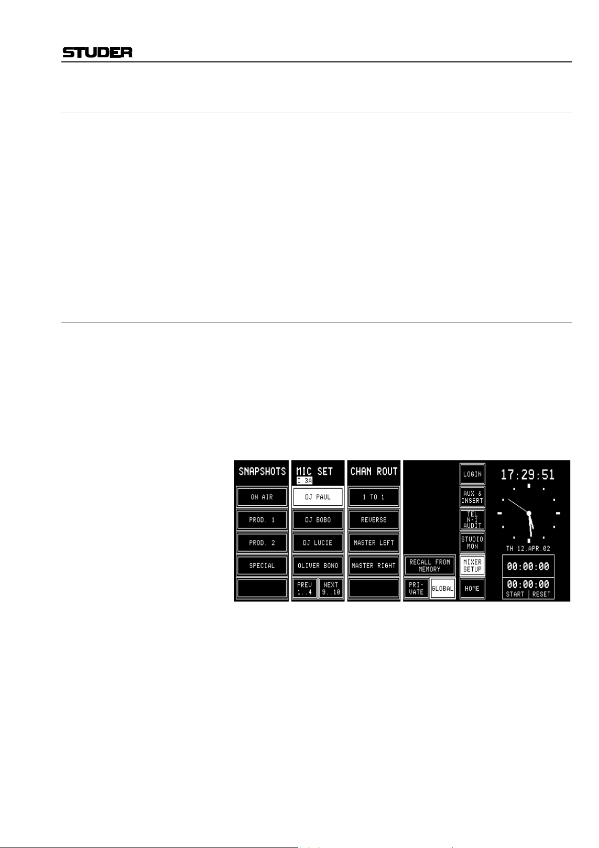
5.7 Mic Settings
A mic (microphone) setting is a set of parameters (EQ, gain, phantom
power) for a single microphone input channel. Thus, every DJ or announcer can store his preferred mic settings and recall them at any time.
Up to four private mic settings for each user (max. 20 users), and up to ten
global mic settings can be stored in the console's flash memory; additional
mic settings can be stored on a PC-Card as well (refer to chapter 5.9).
If the CHAN ROUT section is also displayed on the Mixer Setup page, the
global mic settings are displayed in groups of four. To display the other
groups, use the NEXT... and/or PREV... fields below the MIC SET label
fields.
Mic settings can be named, as the snapshots; these names are displayed on
the corresponding touch field columns on the Mixer Setup page.
5.7.1 Recall a Mic Setting from Memory
To recall a mic setting from the console’s internal flash memory, first open
the Mixer Setup page (SNAPSHOTS/MIC SET/CHAN ROUT) by touching MIXER SETUP, then select a microphone input channel by pressing
the SEL key of the desired channel, then touch the desired MIC SETTING
field. The name of the selected mic setting is highlighted.
Then touch the RECALL FROM MEMORY field. The selected input
channel’s parameters are immediately set to the values of the mic setting.
Selection of another type of input channel (line or digital) is treated as an
error and will not be accepted by the system.
OnAir 1000 Digital Mixing Console
If the last modification was made on a microphone input channel, this
channel is automatically selected and shown in the top line of the Mixer
Setup page. To change the input selection, just touch the SEL key of the
desired fader strip. The physical input being currently active (A or B) of
this input channel is now selected and shown in the top line of the Mixer
Setup page.
Date printed: 23.10.03 SW V 4.0 Master Functions 5-9

OnAir 1000 Digital Mixing Console
5.7.2 Save a Mic Setting to Memory
Creating a mic setting means saving a set of equalizer and gain parameters
for a single microphone input channel under a given name into the console's internal flash memory. This is done by first selecting the microphone
input channel to be stored, then touching a MIC SET field, followed by
SAVE MEM. The keyboard page appears where the mic setting's name can
be edited. Any MIC SET field (also one of these that have already been
used and have a name assigned) can be selected. It will, however, be overwritten by the new mic setting.
Now a new name can be generated, or the already present name can be
overwritten or edited. When touching <--¦ ENTER, the mic setting data
and its new name are saved.
5.7.3 Delete a Mic Setting from Memory
When saving a mic setting, the previously saved data are overwritten. A
mic setting can be deleted, too, without overwriting it with new data.
For deleting a mic setting from the console’s internal flash memory, the
desired mic setting has to be selected. The selected field is highlighted.
After touching the DELETE MEM field, a dialog box will appear. If it is
confirmed, the mic setting will be permanently removed from the memory,
and the text within the selected field is cleared.
5-10 Master Functions SW V 4.0 Date printed: 23.10.03

5.8 Routing
OnAir 1000 Digital Mixing Console
The OnAir 1000 features an input channel router that allows to route the
output of any input unit (including the complete parameter set, as stereo
mode, gain, filter, sends, bus assignment) to any fader strip. Please note
that the two physical inputs A and B of the same input unit cannot be assigned to different fader strips, as the input selector switch is located before the preamplifier.
An input unit signal cannot be routed to more than one fader strip.
5.8.1 Channel Routing
Input Units
A
B
1
Channel Router Fader Strips
1
#
A
B
10
10
The channel routing, i.e. the input unit-to-fader strip assignment, is accessed on the CHANNEL ROUTING page. There is only one user-specific
channel routing per logged-in user available. Should the user have no access permission to the channel routing, this page is not displayed.
The right part of the CHANNEL ROUTING page displays a matrix with
the corresponding number of faders and input channels. The current input
unit-to-fader strip assignment is indicated by the crosspoints.
Date printed: 23.10.03 SW V 4.0 Master Functions 5-11

OnAir 1000 Digital Mixing Console
The program and record master fader assignment is fixed (PGM MASTER
to fader no. 11, REC MASTER to fader no. 12). These two faders can be
disabled (CLEAR) and re-enabled (SET), but not re-assigned to input
channels. They are located at the far right of the grid (“P” and “R”). An
example of this particular CHANNEL ROUTING page is shown below:
Making a Crosspoint On the left part of the CHANNEL ROUTING page, the input unit-to-fader
strip assignment is performed with the two left rotary encoders below the
touch-screen. When turning these encoders, the highlighted horizontal and
vertical lines are moved within the grid. The input channel and fader numbers are displayed above the two rotary encoders, as well as the type of the
selected input unit (MIC/ANALOG/DIGITAL) and the position of the currently selected fader.
Above the input unit-to-fader strip assignment, the input labels are displayed.
The channel routing relates to the physical input. This means that, for example, input B can be selected; when loading this set-up later, input B with
all its input parameters (as input gain, EQ settings, etc.) is automatically
selected. These parameters are input-related and will be automatically rerouted when the input channel is assigned to a different fader.
When the desired crosspoint is found, touch the SET field. A dot appears
at this crosspoint in the grid, indicating the established connection.
The fader to which this input channel had been assigned before is free
now, and its dot jumps outside the grid to the left (fader 07 in the picture
above). The same happens when the CLEAR field is touched after having
selected a connection.
When all settings are done, touch the APPLY field. The new channel
routing is loaded to the work memory. There are two ways to proceed now:
Temporary Routing When touching the EXIT field, the page is left without saving, and the user
can work with the new channel routing.
However, the new routing is not stored in the user's profile. When the user
logs out, the temporary channel routing is lost, and his original channel
routing will be loaded when logging in the next time.
Permanent Routing To store the new channel routing within the user's profile, the SAVE TO
USER PROFILE field has to be touched before exiting the page with
EXIT.
Clearing a Crosspoint When the CLEAR field is touched after having selected a connection, then
this fader strip is free now, and its dot jumps outside the grid to the left.
Protected Connections One or several connections can be protected by the administrator from
being modified, even by users having access permission to the CHANNEL
5-12 Master Functions SW V 4.0 Date printed: 23.10.03

ROUTING page. In such a case, a dashed vertical line is displayed for the
corresponding input unit (channels 01, P, and R in the picture above).
Input Units not Connected to a Fader Strip
There are cases where the signals must be routed “to the background”, i.e.,
it is possible for input channels to be active, but without operating elements on the console surface, e.g. if the user deliberately decides that some
input channels must be in the background.
All input channels currently routed to the background can be displayed in
the CHANNEL ON/OFF page; this page is selected by touching CHN
ON/OFF in the HOME page.
When routing an input unit signal to the background, the audio path remains open, and the audio passes through the console with the fader level
set at the moment of routing the signal to the background. This can be
used, for example, for input channels being controlled in the background
by a broadcast automation system (e.g. DigiMedia) using the serial port.
External MUTE control for the input channel is still available.
Notes: This could be dangerous for a new user taking over the console, or for un-
experienced users. Therefore being in the HOME page, the HOME field
toggles to CHN ON/OFF. When touching this field, the CHANNEL
ON/OFF page is opened (see below), displaying all input channels not assigned to fader strips (i.e., being in the background); the highlighted ones
are open for audio signals (“ON”). Now, the user can switch any input
channel ON or OFF on this page directly by touching the corresponding
field on the screen.
When the PFL function is active at the moment of routing an input channel
to the background, it is automatically switched off.
OnAir 1000 Digital Mixing Console
When powering the console off and on again, the input channels in the
background are always set to OFF, to prevent audio from being played out
unintentionally.
Auto Takeover When a new channel routing is loaded or when a user logs in, the input
unit-to-fader strip assignment is modified. In this moment, the audio level
of an input signal may not correspond to the physical position of the new
fader. As the OnAir 1000 does not feature motorized faders, in such a case
the Auto Takeover LEDs indicate in which direction the fader knob has to
be moved to “catch” the audio level and to get the signal under control
again.
Date printed: 23.10.03 SW V 4.0 Master Functions 5-13

OnAir 1000 Digital Mixing Console
5.8.2 Recall a Channel Routing from Memory
Automatical Recall: Every logged-in user has his own user channel routing that is loaded either
automatically when logging-in, or manually. This is defined by customer
code 0x00000200 (see chapter 11.2.11).
Usually it is easier to load the user-specific channel routing automatically
at log-in; in some cases, however, the channel routing must not be changed
(e.g. when the administrator makes some changes in a user domain).
When the console is switched on, the last channel routing (i.e. the one that
was active before power off) is automatically loaded.
Manual Recall: A user can recall one of the five global channel routings or, when logged
in, his own user channel routing at any time. This is done in the Mixer
Setup page, either after selection of GLOBAL (up to five channel routings
can be recalled by selecting one of them and touching RECALL FROM
MEMORY), or PRIVATE (only one user channel routing can be recalled
for logged-in users by selecting RECALL USER ROUTING).
When the console is switched on, the last channel routing (i.e. the one that
was active before power off) is automatically loaded.
5.8.3 Save a Channel Routing to Memory
After having configured the channel routing as desired (see chapter 5.8.1),
touch the APPLY field. The new channel routing is loaded to the work
memory. When touching the EXIT field, the CHANNEL ROUTING page
is left, and the user can work with the new channel routing. However, this
routing is not yet stored in the user's profile. When the user logs out, the
temporary channel routing is lost; if customer code 0x00000200 is set (see
chapter 11.2.11), his original channel routing will be loaded when logging
in the next time.
To store a modified channel routing within the user's profile, the SAVE
TO USER PROFILE field has to be touched before exiting the page with
EXIT.
Note: The system administrator can set and save his own user channel routing as
described above.
For administrator setting and saving of global channel routings or user
channel routings, please refer to chapter 5.8.5 and chapter 5.10.2.
5-14 Master Functions SW V 4.0 Date printed: 23.10.03

OnAir 1000 Digital Mixing Console
5.8.4 Delete a Channel Routing from Memory (Administrator Only)
Previously stored channel routing data are overwritten when saving a
channel routing, as described in chapter 5.8.3.
For the administrator, it is also possible to delete a global channel routing
without overwriting it by new data. To do this, first the desired channel
routing has to be selected. The selected field is highlighted. After touching
the DELETE MEM field, a dialog box will appear. If it is confirmed, the
channel routing will be permanently removed from the memory, and the
text within the selected field is cleared.
For more information on deleting global channel routings please refer to
chapter 5.10.2.
5.8.5 Channel Routing Administration
In addition to the user's own user channel routing, the administrator can
save the current channel routing to one of the five globally-accessible
channel routings. These can be recalled in the Mixer Setup page. The default and global channel routings can be saved or edited by the administrator; the default user's user routing can also be saved or edited by any
user not logged-in (i.e. the default user), if access permission is given.
Channel Routings:
User Channel Routing The procedure for the system administrator changing a user's channel
routing is described in chapter 5.10.2.
Global Channel Routings Five globally accessible channel routings can only be created by the ad-
ministrator, allowing users to set-up the channel routing for specific
transmissions, e.g. news broadcasts or sports events. Users do not have access to the global channel routings configuration. However, access permission given, a user could load a global channel routing, edit it, and store it
in his own user profile.
Administrator Protection: The administrator can protect specific connections within the channel
routing by selecting the desired cross-point with the horizontal and vertical
lines, and then touching the PROT field. A protected connection is indicated by a dashed vertical line in the grid (see below); this connection cannot be changed by the users, even if they are allowed to change their channel routing. Only the administrator may UNPROT this connection again.
However, the user can change the input selection (A/B) of this input channel, if he has the INPUT SEL access permission.
Date printed: 23.10.03 SW V 4.0 Master Functions 5-15

OnAir 1000 Digital Mixing Console
5.9 Using PC-Cards
Snapshots, mic settings, and global channel routings can be saved to a PCCard or loaded from the card into the console's flash memory. Using PCCards, parameter settings of a console can also be copied to an other console, provided that both have the same configuration.
A PC-Card with a capacity of 64 kB can hold about 20 snapshots.
Notes: Using PC-Cards, it is also possible to exchange snapshot, mic setting,
and/or channel routing data between OnAir 1000, OnAir 2000, and OnAir
2000M2 consoles. However, some restrictions must be considered if the
consoles have different hardware configuration (e.g. number of channels,
number of fader strips, different input unit types).
Only the administrator is allowed to load, save, and delete global channel
routings from/to PC-Card.
File Name Extensions: The three-character DOS file name extensions on the PC-Card will be
generated automatically. The relationship between the file name extension
and the file content is shown in the following table.
Data type File name extension
Global snapshot .gss
Private snapshot .pss
Global mic setting .mis
Private mic setting .mip
Global channel routing .gfm
5.9.1 Load a Snapshot/Mic Setting/Channel Routing from PC-Card
To load a snapshot, a mic setting, or a global channel routing from a PCCard, touch MIXER SETUP followed by LOAD FROM CARD. The page
below will be displayed (please note that the CHAN ROUT area is only
displayed for the administrator). The USER FILTER allows to select different user's data with the fourth rotary encoder.
Snapshots, mic settings, or a global channel routing can only be loaded as
long as there is sufficient empty space available in the console's flash
memory; if not, some of them must be deleted first. They can be selected
for loading by scrolling with the corresponding << or >> fields, followed
by LOAD. After having loaded a snapshot, a mic setting, or a channel
routing, it is not automatically active, but it is available in the Mixer Setup
page and must be recalled with RECALL FROM MEMORY, as described
in chapters 5.6.1, and 5.7.1, or 5.8.2, respectively.
5-16 Master Functions SW V 4.0 Date printed: 23.10.03

OnAir 1000 Digital Mixing Console
5.9.2 Save a Snapshot/Mic Setting/Channel Routing to PC-Card
To save a snapshot, a mic setting, or a channel routing to a PC-Card, first
select a snapshot, a mic setting, or a channel routing in the Mixer Setup
page. Then touch the SAVE CARD field. A keyboard appears for entering
a file name (max. 8 characters, no dots, no spaces), as described in chap-
ters 5.6.2, 5.7.2, and 5.8.3.
After confirmation with ENTER, the snapshot, the mic setting, or the
channel routing is saved on the card.
If an empty file name is entered or if EXIT is touched, the action is cancelled without saving anything to the PC-Card.
Please note that only the administrator is allowed to save channel routings
on the PC-Card.
Exceptions: If the file name already exists on the PC-Card, the action must be con-
firmed before the file is overwritten.
If a user tries to store a file under a file name that is already existing but
has been given by an other user, the existing file will (after confirmation)
be overwritten; it will no more be visible for the initial user.
If the card is full, a dialog box appears, telling that the file cannot be
saved.
5.9.3 Delete a Snapshot/Mic Setting/Channel Routing from PC-Card
To delete a snapshot, a mic setting, or a channel routing from the PC-Card,
DELETE CARD must be touched. The page below is displayed; (please
note that the CHAN ROUT area is only displayed for the administrator).
A snapshot, a mic setting, or a channel routing can be selected for deleting
by scrolling with the corresponding << or >> fields. The selected file and
the snapshot, mic setting, or channel routing names contained in this file
are displayed to the right of the << / >> fields. When touching DELETE,
the console asks for confirmation. After confirmation, the file is deleted
permanently. Once deleted, the data cannot be recovered.
A user can only delete his own, private data from the card. The administrator, however, has access to all (global and private) files on the card. Depending on what selection the administrator has made in the Setup page,
either only the global or only the private files are displayed for him.
The DELETE FROM PC-CARD page remains until either EXIT or one of
the main menu fields is touched.
Date printed: 23.10.03 SW V 4.0 Master Functions 5-17

OnAir 1000 Digital Mixing Console
5.10 Administrator
5.10.1 Features
• The administrator has access to all private and global snapshots, mic settings, and channel routings.
• The administrator has no private snapshots or mic settings, but one user
channel routing.
The administrator's Mixer Setup page is shown above. In this case all
SAVE, DELETE, RECALL, and LOAD actions correspond to global
snapshots, mic settings, and channel routings.
When the administrator touches the PRIVATE field and selects one of the
users, he can modify the private settings of this user (see chapter 5.10.2).
Summary: The displayed private snapshots, private mic settings, and user channel
routing depend on the user logged-in to the console; global snapshots,
global mic settings, and global channel routings are the same for all users.
When a user is not logged-in, i.e. he has not entered any password, he is
automatically treated as the default user. The default user, too, has private
settings; these will, however, not be password-protected, so they can be
overwritten by any other user which is not logged-in to the console.
Global parameter settings can be recalled by any user, but modified by the
system administrator only.
Access
Rights:
Administrator read/write read/write* read/write read/write* read/write read/write
Logged-in
default user
* The administrator can read and write the private snapshots and mic settings of any user,
but he has no own snapshots or mic settings.
user,
Global
Snapshots
read read/write read read/write read read/write
Private
Snapshots
Global
Mic
Settings
Private Mic
Settings
Global
Channel
Routings
User
Channel
Routings
Number of Parameter Sets:
Data Type Number Multiplied by Total Data Records
Global snapshots 5 1 5
Global mic settings 10 1 10
Global channel routings 5 1 5
Private snapshots 4 per user 20 80
Private mic settings 4 per user 20 80
User channel routings 1 per user 22 22
5-18 Master Functions SW V 4.0 Date printed: 23.10.03

OnAir 1000 Digital Mixing Console
5.10.2 Admin Selection of Snapshots/Mic Settings/Channel Routings
The system administrator can display and modify the private snapshot, mic
setting, and channel routing data of any user.
This feature has been implemented in order to enable the setting of parameters in a private snapshot, mic setting, or channel routing to which the
particular user has no access. All actions, such as RECALL FROM MEMORY, SAVE (to) MEM, DELETE (from) MEM, LOAD FROM CARD,
SAVE (to) CARD, and DELETE (from) CARD, concern the selected
user's data. No other actions on the console can be affected.
Snapshots and Mic Settings: After selecting PRIVATE in the Mixer Setup page, the second rotary en-
coder from the left (the one below the user’s name label) allows to select
the user's name. In this mode the system administrator can LOAD, RECALL, SAVE, or DELETE all the data being displayed.
Channel Routing: With RECALL USER ROUTING, the system administrator can activate
the user channel routing of the user selected with the rotary encoder. With
RECALL ADMIN ROUTING he activates his own user channel routing.
The procedure for changing a user's channel routing is as follows:
• Log-in as administrator,
• touch MIXER SETUP,
• SYSTEM CONFIG,
• USER ADMIN,
• select the desired user,
• touch EDIT,
• SET CHANNEL ROUTING,
• modify the channel routing,
• touch BACK,
• SAVE,
• EXIT.
Date printed: 23.10.03 SW V 4.0 Master Functions 5-19

OnAir 1000 Digital Mixing Console
5.10.3 Users with and without a Password
When a normal user enters the Mixer Setup page before logging-in (which
means he is treated as the default user), he works with the default user's
data. He can LOAD, RECALL, SAVE, or DELETE all of the default user's
data in the console's memory or on the PC-Card. These data can, however,
be used, saved, overwritten, or deleted by any other user who is not logged
in.
The Mixer Setup page offers a PRIVATE field next to the GLOBAL field,
allowing the user – after having logged-in – to access his own, protected
private snapshots and mic settings.
A user can recall his user channel routing in the Mixer Setup page, after
selection of PRIVATE (only one user channel routing can be recalled by
selecting RECALL USER ROUTING); for more information on this subject please refer to chapter 5.8.2.
Should the user have access permission to the system configuration and/or
channel routing, the corresponding SYSTEM CONF./ROUTING fields
would be displayed here as well.
A user can decide to work with the global data although he is already
logged-in. If the GLOBAL field is touched, the Mixer Setup page will look
as shown below, where he can recall (but not modify) the global snapshots,
mic settings, and channel routings; the CHAN ROUT area is suppressed if
no global channel routings are available. Should the user have access permission to the system configuration and/or channel routing, the corresponding SYSTEM CONF./ROUTING fields would be displayed here as
well.
5-20 Master Functions SW V 4.0 Date printed: 23.10.03

5.11 User Administration
USER ADMINISTRATION is only accessible for the system administrator. Refer to chapter 10 for details on how to set up function access permission and new user accounts.
OnAir 1000 Digital Mixing Console
5.12 System Configuration
System configuration is a separate function group that can be accessed
only by the system administrator or by users having access permission. It is
separately described in detail (refer to chapter 11).
Date printed: 23.10.03 SW V 4.0 Master Functions 5-21

OnAir 1000 Digital Mixing Console
5.13 Watch and Stopwatch
The watch and stopwatch functions are displayed on the right-hand side of
the touch-screen (except when the keyboard or routing pages are active).
The term “watch” refers to the time-of-day in analog and digital format,
the day-of-week, and the date in an abbreviated format.
The term “stopwatch” refers to both the fader and the user stopwatches.
The fader stopwatch measures the time the most recently used channel
fader has been opened. The user stopwatch works like a normal stopwatch
with START/STOP and RESET keys located directly below the touchscreen.
Below, the HOME page with the watch and stopwatch displays and functions is shown.
5.13.1 Watch
The watch gives a time, day-of-week, and date display. The default time
reference is an internal, battery-buffered real-time clock (RTC). The RTC
continues to run even when the console is switched off. Therefore it is unnecessary to set the watch at power-up. The RTC can also by synchronized
by the time signal fed to the TimeSync input connector. If synchronization
is established, the top right corner of the touch-screen shows a small “S”
(Sync OK).
Changes to the internal time reference and the time and date formats can
be made by the system administrator on the TIME page (MIXER SETUP,
SYSTEM CONFIG., TIME). For details, refer to chapter 11.2.5.
Both time and date can be displayed in two formats, as shown below:
Time Format Digital Time Indication
05:00:00 p.m. 12 hour time format
17:00:00 24 hour time format
Date Format Example
DD.MMM.YY MO 20.MAR.02
MMM-DD-YY MO MAR-20-02
5-22 Master Functions SW V 4.0 Date printed: 23.10.03

5.13.2 Fader Stopwatch
The upper one of the two stopwatches is called the fader stopwatch. It
always restarts at 00:00:00 when a new audio channel is activated (e.g.
channel ON, fader open, and output bus selected). In other words, it displays the elapsed time of the audio channel opened last.
This function can be enabled or disabled for any desired audio channel via
the MIXER SETUP/SYSTEM CONFIG./INPUT menu, item TIMER
START YES/NO.
The counter stops when the audio channel that started the stopwatch is
switched OFF, or its fader is closed.
Note: If more than one audio channel has caused the fader stopwatch to restart,
only the last audio channel’s time is displayed.
5.13.3 User Stopwatch
The user stopwatch is located just below the fader stopwatch. It is controlled by two keys on the console’s surface located below the digits of the
display. One key starts and stops the timer, the other resets the timer.
OnAir 1000 Digital Mixing Console
Key Label Description
START
STOP
RESET
START Start timer if stopped
STOP Stop timer if running
RESET
Reset timer regardless
whether stopped or running
Date printed: 23.10.03 SW V 4.0 Master Functions 5-23

OnAir 1000 Digital Mixing Console
5.14 PGM and REC Master Faders
The console provides two master faders (PGM, fader no. 11, and REC,
fader no. 12) located on the far right of the CHANNEL ROUTING page
(“P” and “R”). Their assignment is fixed, they cannot be re-assigned to input channels.
Specifications: • In the audio path, the master faders are located before the insert points
(also refer to the block diagram in chapter 1). If an insert is assigned to
one of the master outputs, the corresponding IN1 or IN2 LED is on;
• No ON/OFF function is available for the master outputs;
• PFL function is not available;
• Overload indication is available;
• Master level can be controlled by Monitora extended commands;
• Signaling (ON-AIR, CR-MIC, and STUDIO-MIC) as well as CR/Studio
CUT/DIM are logically linked to the master faders.
5.14.1 Fixed Master Levels
If only fixed levels of the PGM and/or REC master output signal(s) are
required, it is possible to enter these levels in the DEFAULT MASTER
LEVEL window on the COMMON SETTINGS page in a –7...+5 dB
range. The fixed level for a master output becomes active when the corresponding master fader is disabled by selecting CLEAR in the CHANNEL
ROUTING page. For re-enabling, the CLEAR field then changes to SET.
Important: This setting directly affects the level of the main output signals. Please be
careful when changing this parameter.
5-24 Master Functions SW V 4.0 Date printed: 23.10.03

6 MONITORING
6.1 Control Room Monitoring
The CR monitoring source selector has 10 keys to select one out of six
internal and four analog external sources. The key of the selected source is
illuminated.
Key Source Description
AUX 2
AUX 1
AUDIT
PFL
OnAir 1000 Digital Mixing Console
Auxiliary 2
Auxiliary 1
Audition
Record output
Program output
(on-air)
PFL PFL sum. PFL is illuminated if selected.
General purpose output bus. AUX2 is illuminated
if selected.
General purpose output bus. AUX1 is illuminated
if selected.
General purpose output bus. The input channels
to the audition bus are configurable. AUDIT is
illuminated if selected.
Output signal of the record master output. ΣREC
is illuminated if selected.
Output signal of the on-air master output. ΣPGM
is illuminated if selected.
EXT 3
EXT 2
EXT 1
F 5
F 4
F 3
F 2
F 1
External 3
External 2
External 1
Off-air
Function keys
F1 to F5
General purpose analog stereo input signal.
EXT3 is illuminated if selected.
General purpose analog stereo input signal.
EXT2 is illuminated if selected.
General purpose analog stereo input signal.
EXT1 is illuminated if selected.
General purpose analog stereo input signal (e.g.
tuner). OFF AIR is illuminated if selected.
Spare keys for future functions.
Two additional keys are used to control the monitoring loudspeakers in the
control room. The functions of these keys are described in the table below.
Key Function Description
DIM
CUT
–20 dB
Mute
The output level to the CR monitor loudspeakers
is reduced by 20 dB. DIM is illuminated if selected.
The output to the CR monitor loudspeakers is
muted. CUT is illuminated if selected.
A volume control knob (MON ) is used to set the level sent to the CR
monitor speakers.
As long as one of the microphones in the control room (DJ or guest microphone) is on, the monitor speakers are muted. In this case the CUT key is
illuminated.
Date printed: 23.10.03 SW V 4.0 Monitoring 6-1

OnAir 1000 Digital Mixing Console
If the monitoring source is AUDIT (audition bus), the monitor speakers are
either dimmed (DIM key illuminated), muted (CUT key illuminated), or
not affected at all, according to the configuration (see chapter 11.2.2 for
details).
If talkback is active, the level of the monitor speakers is dimmed by 20 dB
and the DIM key is illuminated.
External CR DIM: Provided that the corresponding Customer Code has been activated, an
additional control input signal on the “SIGN.” connector allows to reduce
the level of the CR monitor speakers by 20 dB (refer to chapters 11.2.11
and 14.11 for details).
The signal on the PFL bus is reproduced by the console’s built-in speaker.
The same speaker is used for talkback. The volume is adjusted with the
PFL/TB potentiometer.
For monitoring purposes, a headphones connector is provided on the left
side below the hand rest of the console. Three keys allow different monitoring modes, as described below:
Key Function Description
PFL
MON
PFL
MON
PFL
PFL/CR monitor
CR monitor
The headphones signal is the stereo PFL signal.
PFL is illuminated if selected.
The left headphones signal is the mono PFL
signal, while the right headphones signal is the
mono CR signal as selected by the monitor
source selector. If no PFL is selected, the headphones signal is the stereo CR signal as selected.
MON/PFL is illuminated if selected.
The headphones signal is the same stereo signals
as selected by the source selector for the monitor
speaker. MON is illuminated if selected.
The CUT and DIM keys have no effect on the headphones signal. The
headphones output is not muted if one of the control room microphones is
on. The incoming talkback signal from the studio is mixed to the headphones output. For improved intelligibility, the monitoring signal is attenuated by 20 dB.
The PFL to MONITOR function feeds the PFL signal to the monitor loudspeakers, if PFL is selected on any channel. The normal monitoring signal
is muted for as long as any PFL keys are active.
Key Function Description
The PFL signal is routed to the monitor speakers
PFL
MON
PFL to MONI-
TOR
if PFL on any channel is active. If no PFL is selected, the monitoring signal is the stereo CR
signal as selected. PFL > MON is illuminated if
active.
A volume control knob (PHONES ) adjusts the headphones listening
level.
6-2 Monitoring SW V 4.0 Date printed: 23.10.03

6.2 Studio Monitoring
The built-in studio monitoring functions are based on a touch-screen menu
on the control screen. The STUDIO MONITORING SOURCE page allows
one of six sources to be selected for routing to the studio speakers and
headphones.
The table below lists the available sources.
OnAir 1000 Digital Mixing Console
Label Function Description
ΣPROGRAM
AUX 1
AUX 2
PFL
OFF AIR
EXT 3 External input
Program output
(on-air)
Auxiliary
output 1
Auxiliary
output 2
Pre-fader lis-
tening output
External Off-air
input
Output signal to the transmitter. ΣPROGRAM is
highlighted if selected.
General purpose output sum. AUX1 is highlighted
if selected.
General purpose output sum. AUX2 is highlighted
if selected.
PFL sum. PFL is highlighted if selected.
General purpose input signal, usually from receiver. OFF AIR is highlighted if selected.
General purpose input signal. EXT 3 is highlighted
if selected.
As soon as one of the fields is touched, the corresponding signal is routed
to the studio, and the field is highlighted.
The monitoring source selection can be controlled from the studio via external pushbuttons thanks to the parallel interface. The monitor speaker
and headphones levels can independently be controlled by two potentiometers located in the studio.
The studio monitoring speakers are muted if one of the studio microphones
is on. The headphones are not muted in this case.
During talkback from the CR to the studio, the volume for the studio
speakers is reduced by 20 dB. The talkback signal from the CR to the studio is not reduced and has therefore the normal listening level on both the
studio monitor speakers and the studio monitor headphones.
Date printed: 23.10.03 SW V 4.0 Monitoring 6-3

OnAir 1000 Digital Mixing Console
6.3 Talkback
There is a choice among five talkback destinations from any control room
(CR) microphone. A key is assigned for each destination as can be seen in
the table below.
Any microphone in the control room, including the integrated TB microphone, can be the CR microphone, if “TB SOURCE” is set to “CR” in the
INPUT CONFIG. page.
Key Function Description
The connection between DJ mic and Clean-feed
B (N–1B, e.g. telephone 2) is established for as
long as this key is pressed.
The connection between DJ mic and Clean-feed
A (N–1A, e.g. telephone 1) is established for as
long as this key is pressed.
The connection between DJ mic and Auxiliary 2 is
established for as long as this key is pressed.
The connection between DJ mic and Auxiliary 1 is
established for as long as this key is pressed.
The connection between DJ mic and the Studio is
established for as long as this key is pressed.
N–1 B
N–1 A
AUX 2
AUX 1
TB to Tele-
phone 2
TB to Tele-
phone 1
TB to
Auxiliary 2
TB to
Auxiliary 1
TB to Studio
The console’s built-in PFL/TB loudspeaker and the headphones are used
for talkback listening in the CR, while in the studio the monitoring speakers and the headphones are used.
The parallel studio interface on the “STUDIO MON CTRL” connector
allows the connection of three pushbuttons for talkback target selection.
The possible targets are: CR, Clean-feed 1 (N–1 A/TEL1), and Clean-feed
2 (N–1 B/TEL2). For talkback from the studio, the studio microphones are
used (“TB SOURCE” is set to “STUDIO”).
An additional, electronically balanced talkback line input on the “STUDIO
MONITOR (AUDIO) B” connector as well as additional talkback to CR
and to studio control inputs (on the “EXT PFL CTRL” connector) are provided.
Please refer to the pin assignment tables and the connection diagrams in
chapter 14.11.
6-4 Monitoring SW V 4.0 Date printed: 23.10.03

6.3.1 Talkback Settings
Signaling and talkback can be configured independently. The “SIGN.”
setting in the INPUT CONFIG. page is used only for signaling (red light)
and monitoring (cut and dim).
The “TB SOURCE” parameter in the INPUT CONFIG. page sets the assignment of the talkback source, i.e. the input channel to the TB bus
(NONE, from CR, or from Studio).
OnAir 1000 Digital Mixing Console
During talkback from the Studio, the studio speakers are dimmed only if at
least one input channel is configured as “SIGN.” = STUDIO and “TB
SOURCE” = STUDIO. The same applies for talkback from the control
room.
Note: Configuration of talkback and signaling is also possible for analog line or
digital input channels as well as for a TB mic input channel, as shown by
the following screenshots.
Date printed: 23.10.03 SW V 4.0 Monitoring 6-5

OnAir 1000 Digital Mixing Console
For deactivating the internal TB microphone and activating the external
TB mic inputs, the INPUT CONFIG. page for the channels 11 and 12 is
used:
6.4 External PFL
The OnAir 1000 provides an external PFL audio input. If the EXT PFL
key is pressed, the key is illuminated, and the signal at the EXT PFL input
(EXTERNAL MONITOR INPUT A connector) is routed to the PFL bus.
A control output is activated if EXT PFL is active. In addition, the EXT
PFL function can be activated by a dedicated control input on the EXT
PFL CTRL connector (refer to chapter 14.11).
With this feature, the OnAir 1000 is well-suited for the integration with a
broadcast automation (CAB, computer-assisted broadcasting) system.
These systems need a separate PFL input that can be activated by the CAB
system itself.
Key Function Description
Switches the EXT PFL OUT control output on and
EXT
PFL
External PFL
off, and routes the EXT PFL audio input signal to
the PFL bus. The key is illuminated if active, or if
a control signal is applied to the EXT PFL input.
6-6 Monitoring SW V 4.0 Date printed: 23.10.03

7 SIGNALING
OnAir 1000 Digital Mixing Console
For control room and studio, signaling is provided by means of opencollector outputs (9-pin D-type connector “SIGN.” on the rear of the console; for connection details, refer to chapter 14.11).
One output is available for each of the following statuses:
• Control Room microphone is on-air,
• Studio microphone is on-air, and
• Any signal from the console is on-air (i.e., a fader is open, this channel's
ON key is active, its signal is routed to the PROGRAM and/or the RECORD bus, and, if configured, the corresponding master fader is open).
The CR-MIC and STUDIO-MIC indicators in the monitoring section of the
console are illuminated when the corresponding control output is active.
SIGN. Output Active if:
CR MIC OUT At least one input channel of a CR or DJ microphone is active (chan-
nel ON, fader open, assigned to program or record bus, corresponding master fader open).
STUDIO MIC OUT At least one input channel of a studio microphone is active (channel
ON, fader open, assigned to program or record bus, corresponding
master fader open).
PGM OUT Depending on ON-AIR INDICATION condition selected in the COM-
MON SETTINGS page:
• ΣPROGRAM AND ΣRECORD – at least one input channel is
active (channel ON, fader open, assigned to program or record
bus, corresponding master fader open).
• ΣPROGRAM – at least one input channel is active (channel ON,
fader open, assigned to program bus, PGM master fader open).
• ΣRECORD – at least one input channel is active (channel ON,
fader open, assigned to record bus, REC master fader open).
The ON AIR INDICATION condition for the PGM OUT control signal
can be set in the COMMON SETTINGS page (reached by touching
MIXER SETUP followed by COMMON), if access permission is available.
An additional ON AIR IN opto-coupler input on the SIGN. connector can
be used for illuminating the ON-AIR indicator in the monitoring section of
the console.
Note: For information on the DEFAULT MASTER LEVEL window on the
COMMON SETTINGS page, please refer to chapter 5.14.1.
Date printed: 23.10.03 SW V 4.0 Signaling 7-1

OnAir 1000 Digital Mixing Console
7-2 Signaling SW V 4.0 Date printed: 23.10.03

8 MACHINE CONTROL
The OnAir 1000 provides different control inputs and outputs. These can
be used e.g. for switching an input channel on and off, or for starting,
stopping, and cueing of the connected source unit (as CD/cartridge/MD
players, tape recorders, or a CAB system). The control inputs and outputs
are input channel-related and are re-assigned together with the input channel signal to the respective fader strip if the channel routing is changed.
Each audio input holds two control outputs and one control input on Dtype connectors. The signals are:
• CTRL OUT 1 (normally used for fader start, but configurable for other
functions; see chapter 8.2.1)
• CTRL OUT 2 (configurable functions see chapter 8.2.2)
• CTRL IN (configurable functions see chapter 8.3.1)
The status of the output signals depends on the control elements of the
fader strip (keys 1 to 3, fader, input selection, channel routing, and output
bus assignment), as well as on the console configuration.
Each input channel has two physical audio inputs, each of them with own
control input and two control outputs, allowing to control every external
source separately.
OnAir 1000 Digital Mixing Console
8.1 Keys and LEDs
Key 1/LED 1 The first key (labeled “PFL”) is always used to activate/deactivate the PFL
Key 2/LED 2 The second key (labeled “ON”) is used either to switch the input channel
PFL
ON
function; if active, LED 1 is illuminated.
The PFL function can affect the CTRL OUT1 and/or CTRL OUT2 control
signals, depending on the configuration. This configuration is performed in
the center part of the INPUT CONFIG. page and is identical for all types
of input units.
ON or to toggle the input channel ON/OFF, depending on the configuration of key 3. This function affects the CTRL OUT1 control signal. LED 2
always indicates the input channel's ON/OFF status.
Date printed: 23.10.03 SW V 4.0 Machine Control 8-1

OnAir 1000 Digital Mixing Console
Key 3/LED 3 The functionality of the third key (labeled “OFF”) depends on the console
OFF
configuration. It can act as channel OFF key or trigger a LOCATE function. The key 3 functionality is set in the COMMON SETTINGS page:
Console configuration (valid for all channels):
Key 3 (“OFF”) function Key 2 (“ON”) function
(Channel) OFF (Channel) ON
LOCATE (Channel) ON/OFF
LOCATE (Channel) ON *
Channel ON/OFF affects the CTRL OUT1 control signal of the selected
input channel, and the LOCATE function defines the status of the CTRL
OUT2 control signal of the selected input channel.
* To protect a channel from being switched off inadvertently, the OFF func-
tion can be disabled. This setting is performed in the COMMON SETTINGS page; it is valid for all channels of the console simultaneously.
Note: If this setting is selected, no input channel can be switched off by pressing
a key – therefore, either closing the fader must do, or an external pushbutton per input channel has to be added. For this purpose, a CTRL IN control
input per input channel is provided; please refer to chapter 8.3.1. Select the
option “CTRL. IN – EXT. ON/OFF” in the INPUT CONFIG. page.
LED 3 is illuminated if an external device indicates ready status using the
CTRL IN input signal of the selected input channel, or if the CAB system
indicates “ready for playback” via the serial interface (“Monitora” protocol, refer to chapter 9).
8-2 Machine Control SW V 4.0 Date printed: 23.10.03

8.2 Control Outputs
8.2.1 CTRL OUT1
OnAir 1000 Digital Mixing Console
This open-collector output is normally used to start external devices, such
as CD players or a CAB system, to play the next track. On the INPUT
CONFIG. page (see chapter 8.1), other functions can be assigned individually for each audio input.
Input configuration (for each channel individually):
CTRL OUT1 mode CTRL OUT1 signal
NOT ACTIVE Output always open (inactive).
Active if either PFL key is pressed (independent of fader position), or if
PFL/ON & FADER
ON & FADER
ON LAMP
ON key is pressed and fader is open (fader start function, causing the
source to be started as well when PFL key is pressed).
Active if ON key is pressed and fader is open (standard fader start
function).
Active if input channel is ON; used as acknowledgement if the input
channel is remotely controlled.
8.2.2 CTRL OUT2
This open-collector output can be used to re-park an external device, such
as a CD player, after cueing, or for signaling, or as an acknowledgement
for ON status. It can be configured individually for each input in the INPUT CONFIG. page (see chapter 8.1).
Input configuration (for each channel individually):
CTRL OUT2 mode CTRL OUT2 signal
NOT ACTIVE Output always open (inactive).
Active if key 3 (“OFF”, configured as LOCATE key) is pressed while the
LOCATE KEY
PREVIEW
LOCATE PFL KEY
LOCATE PFL /
LOC KEY
ATTENTION
ON LAMP
FADER
STOP_PULSE
channel is closed (fader closed or channel OFF). Using this function, a
source that has been pre-listened before can be reset to the start point.
Active as long as key 1 (“PFL”) is pressed while the channel is closed
(fader closed or channel OFF). Using this function, a source can be
started for pre-listening.
Active for approx. 0.3 s when key 1 (“PFL”) is switched off while the
channel is closed (fader closed or channel OFF). Using this function, a
source can be given a locate command to return to the start point.
Combination of the LOCATE KEY and LOCATE PFL KEY functions:
• Output is active for approx. 0.3 s when key 1 (“PFL”) is switched
off while the input channel is closed (fader closed or channel
OFF). Using this function, a source can be given a locate command to return to the start point.
• Output is active if key 3 (“OFF”, configured as LOCATE key) is
pressed while the input channel is closed (fader closed or channel
OFF). Using this function, a source that has been pre-listened
before can be reset to the start point.
Active as long as key 3 (“OFF”, configured as LOCATE key) is pressed;
can be used for “ready” signaling.
Active if input channel is ON; used as acknowledgement if the channel
is remotely controlled.
Generates a fader start pulse (approx. 0.2 s) at CTRL OUT 1 and a
fader stop pulse (approx. 0.3 s) at CTRL OUT 2, but only if CTRL OUT
1 is configured as ON & FADER or PFL/ON & FADER.
Date printed: 23.10.03 SW V 4.0 Machine Control 8-3

OnAir 1000 Digital Mixing Console
8.3 Control Inputs
8.3.1 CTRL IN
A CTRL IN control input is available for each audio input channel. This
input channel's function can be selected in the INPUT CONFIG. page (see
chapter 8.1).
Note: An optional, external control interface (1.942.803.xx) can be used for the
following functions of a single input channel:
• Electrical isolation between CTRL OUT and the connected source (re-
• Conversion from the continuous fader start signal to electrically isolated
• Remote control of an input channel using separate ON and OFF keys,
• Remote control of an input channel through a CAB system sending a
Additional information on this interface can be found in the circuit diagrams chapter of the OnAir 1000 Service Manual.
Input configuration (for each channel individually):
CTRL IN mode CTRL IN signal
NOT ACTIVE No function (input signal is ignored)
READY Key 3 (“OFF”) is illuminated as long as CTRL IN is active
EXT. MUTE
EXT. ON/OFF
Input channel is muted as long as CTRL IN is active (e.g. cough
key)
Toggles the channel ON/OFF; used e.g. for ON/OFF button on
speaker’s desk, or for remote control through CAB system
lay with make contact);
start and stop pulses;
logically linked with the ON LAMP signal. The ON and OFF keys in
the console remain functional;
continuous control signal as long as an input channel must be on, logically linked with the ON LAMP signal. The external command is overridden by the ON and OFF keys in the console.
8.3.2 EXT PFL Input
An external PFL control input is available on the “EXT PFL CTRL” connector at the rear of the console (refer to chapter 14.11). It allows e.g. to
open the EXT PFL pre-listening audio path by a CAB system.
8-4 Machine Control SW V 4.0 Date printed: 23.10.03

OnAir 1000 Digital Mixing Console
OnAir 1000
D730/D731 CD player
CTRL IN
CTRL OUT1
BR_PAUSE
FAD1
SR_REVIEW
CTRL OUT2
CTRL IN
CTRL OUT1
BR_PAUSE
FAD1
SR_LOCATE
CTRL OUT2
OnAir 1000
D730/D731 CD player
a)
b)
8.4 CTRL OUT1/2 & CTRL IN Application Examples
Configuration
Application
Fader start/stop with:
Fader open/close, or channel ON/OFF
Fader start/stop with:
Fader open/close, or channel ON/OFF, or
PFL ON/OFF
Review function of Studer D730/D731:
pre-listening with PFL and subsequent locate
to the last cue address. Afterwards: PLAY
with fader start; see Notes 1 and 2
Pre-listening with PFL and subsequent locate
to the start; console sends an 0.2 s locate
pulse on CTRL OUT2. Afterwards: PLAY with
fader start; see Note 1
Manual locate to the start, using
OFF/LOCATE key 3; see Note 1
Pre-listening with PFL and subsequent locate
to the start. Manual locate also available; see
Note 1
Fader start pulse and fader stop pulse (on
different control outputs)
Control of any external signal with key 3
(“OFF”)
Reflects the ON lamp status to CTRL OUT1 ON LAMP — — CTRL OUT1 –> any control input
Reflects the ON lamp status to CTRL OUT2 — ON LAMP — CTRL OUT2 –> any control input
Note 1: Function is available only if the corresponding console channel is not active; “channel active” = fader open and channel ON
and channel assigned to PGM or REC bus.
Note 2: D730/D731 configuration checksum example, suited for this function: 4050631164470. For more information on this subject,
please refer to the D730/D731 operating instructions manual, order no. 10.27.1672
Note 3: Combination of different applications is possible if allowed by the CTRL OUT1/2 wiring.
Note 4: DO NOT change the settings while any of the control output signals is active!
CTRL OUT1;
see Note 4
ON & FADER — —
PFL / ON &
FADER
ON & FADER PREVIEW —
PFL / ON &
FADER
— LOCATE KEY LOCATE
PFL / ON &
FADER
ON & FADER
or
PFL / ON &
FADER
— ATTENTION LOCATE CTRL OUT2 –> any control input
Configuration
CTRL OUT2;
see Note 4
— —
LOCATE PFL
KEY
LOCATE PFL /
LOC KEY
FADER STOP
PULSE
Configuration of
key 3
(“OFF”/LOCATE);
see Note 4
—
LOCATE
—
Connection(s) OnAir 1000
–> controlled source (e.g.
CD player, cart/tape recorder
CTRL OUT1 –> remote control
input “fader start”
CTRL OUT1 –> remote control
input “fader start”
CTRL OUT2 –> Studer D730/
D731, remote control input
“SR_REVIEW”; see fig. a)
CTRL OUT1 –> remote control
input “fader start”, CTRL OUT2
–> remote control input “locate”;
see fig. b)
CTRL OUT2 –> remote control
input “locate”; see fig. b)
CTRL OUT1 –> remote control
input “fader start”; CTRL OUT2
–> remote control input “locate”;
see fig. b)
CTRL OUT1 –> fader start pulse,
CTRL OUT2 –> fader stop pulse;
used for any remote control input
using pulses instead of a static
signal
Date printed: 23.10.03 SW V 4.0 Machine Control 8-5

OnAir 1000 Digital Mixing Console
8-6 Machine Control SW V 4.0 Date printed: 23.10.03

9 AUTOMATION
9.1 Introduction
Studer DigiMedia: Information on how to connect and operate the OnAir 1000 mixing con-
OnAir 1000 Digital Mixing Console
The OnAir 1000 supports external CAB (computer-assisted broadcasting)
systems. A serial interface (RS232/RS422) is used for communication with
the CAB system.
sole with a DigiMedia CAB system is given in the current DigiMedia operating instructions.
The serial interface protocol is based on the “Schnittstellen-Spezifikationen Regiepult” of DSA (Digitale Steuerungs- und Automationstechnik, Thomas Volgmann) furthermore called [MONPROT], which was
defined by VCS and Siemens.
The implementation in the OnAir 1000 is a subset of [MONPROT].
For detailed information on the telegrams implemented in the OnAir 1000,
please refer to the “Communication Protocol for Broadcast Automation”
document [BCACOM] (available on request).
9.2 Features of the OnAir 1000 CAB Support
Pre-Listening
News 1
Output 3
Output 2
Output 1
Channel A Channel B Channel C
[MONPROT]
News 2
Ext. PFL
Input
OnAir Console
• Serial interface: Serial RS232/RS422 standard communication interface
based on [MONPROT].
• 2 x 12 character text display per channel.
• Music and speech output:
The CAB can control the output assignment (program/record bus) of the
currently selected input of a channel.
Date printed: 23.10.03 SW V 4.0 Automation 9-1

OnAir 1000 Digital Mixing Console
9.3 Application Handling
9.3.1 Configuration for Automation Control
Input channels must be assigned to the automation system in the console
configuration in order to be controlled by an external CAB system.
AUTOMATION CONFIG. is reached from the SYSTEM CONFIG. page:
The AUTOMATION CONFIG. page allows each input channel to be assigned to the CAB system.
Please note that these channels' labels must be named “DIGI 1” through
“DIGI 3”. Normally three input channels are used with the CAB system; a
fourth “DIGI 4” input channel is possible, but unusual.
9.3.2 Communication Time-Out
If no valid telegram is received from the CAB within approx. 30 seconds,
the OnAir 1000 assumes that the communication is interrupted.
In this case it stops sending telegrams and the following actions are performed:
• All input channels are deselected;
• A warning: “Communication to Broadcast Automation lost!” is displayed.
After the next or first telegram from the CAB, communication will be reestablished.
The information: “Communication to Broadcast Automation established!”
is generated.
9-2 Automation SW V 4.0 Date printed: 23.10.03

OnAir 1000 Digital Mixing Console
9.3.3 Output Selection
The CAB is able to control the output assignment (program/record bus) of
the currently selected input of any input channel. This allows, for instance,
to route speech to the program output, and music to the record output.
9.3.4 Start a New Title from Schedule
In automation mode, the CAB can start a new title automatically (it is also
possible to start new titles manually; then, the operator opens the fader
while the input channel is already switched ON, or switches the desired
channel ON while the fader is already open).
Automatic New Title Start: The CAB can control the console automatically. This automatic mode
must be activated from within the CAB and can, for example, be used for
controlling a program during the night without any assistance.
If the CAB runs in automatic mode, it starts playback of the source and
opens the appropriate input channel with the pre-defined level and fade-in
time. This will send a new audio level to the DSP, and switch the input
channel ON in any case.
If a take ends, the CAB performs a cross-fade on its audio card, the selected channels on the console remain open.
If the CAB changes the audio level, the channel changes into auto takeover
mode. This means that the audio level (i.e. actual DSP level) and the fader
level (i.e. physical position of the fader knob) differ for more than a specified auto takeover window. If the fader is moved now, nothing will change
until the physical position of the fader knob is within the auto takeover
window. Then the auto takeover mode is left.
Auto takeover mode is indicated in the fader strip by the two AUTO
AUTO
TAKE
OVER
TAKEOVER arrow LEDs. The operator can recognize the direction in
which he has to move the fader in order to leave auto takeover mode and
take control of the signal level. If the physical position of the fader is
brought within the auto takeover window or if it accidentally is situated
within the window, both arrow LEDs will be illuminated.
AUTO
TAKE
OVER
Channels not con-
trolled by a CAB
system
AUTO
TAKE
OVER
Audio level above
the fader position –
move fader down
AUTO
TAKE
OVER
Audio level below
the fader position –
move fader up
AUTO
TAKE
OVER
Audio level
equal to the
fader position
Date printed: 23.10.03 SW V 4.0 Automation 9-3

OnAir 1000 Digital Mixing Console
9.3.5 Indication of the Currently Playing Input Line
As the OnAir 1000 is not equipped with motor faders, a clear indication of
the channel currently “playing” is necessary.
Under the following conditions the respective channel label is in continous
scrolling mode, indicating “ON-AIR” if:
• Fader (audio level) is open;
• The channel is switched ON;
• The channel is assigned to program and/or record bus (as defined in the
Common Settings page);
• The channel is selected by the CAB (SOURCE_SELECTION).
9.3.6 Pre-Listening
When starting the pre-listening function in the CAB system by clicking on
the LISTEN button on the CAB screen, followed by selecting a title, the
CAB system immediately sends the desired title over the fourth channel of
its audio card. At the same time, it opens the external PFL input, so that
the desired title is audible in the console's PFL loudspeaker.
9.3.7 Time Synchronization
The CAB is able to set the console's internal clock (time and date) if TIME
SYNC. is set to AUTOMATION in the TIME & DATE FORMAT page;
refer to chapter 11.2.5.
9-4 Automation SW V 4.0 Date printed: 23.10.03

10 USER MODES
10.1 Purpose of User Modes
The console is used in different studios with different working practice
and different personnel structure. A large part of users in broadcast studios
is not technically oriented. A mixing console meeting their requirements
must be simple to use, reliable and free of “unnecessary” controls and displays. Setting of a wider range of console parameters, saving of console
settings (snapshots), and modifications of the console configuration have
to be left for technically more competent users (studio technicians, chief
engineer). It is also necessary to protect parts of system data and give the
permission to change them only to a restricted number of users. In order to
satisfy these needs, the OnAir 1000 console supports individual user access rights.
Three classes of users are defined for the OnAir 1000; these are:
Default User: • No password required;
• Private snapshots and mic settings;
• User channel routing;
• Function access rights according to the configuration.
Normal User: • Password-protected;
• Private snapshots and mic settings;
• User channel routing;
• Function access rights according to the configuration.
System Administrator: • Password-protected;
• User channel routing;
• Unlimited access rights to all functions;
• Defines new users;
• Defines access rights for all users;
• Stores global snapshots, global mic settings, and global channel routings.
• Stores private snapshots, private mic settings, and user channel routings
for all users.
OnAir 1000 Digital Mixing Console
The table in chapter 10.2 shows the functions to which access is configurable in the OnAir 1000.
Date printed: 23.10.03 SW V 4.0 User Modes 10-1

OnAir 1000 Digital Mixing Console
10.2 Access to Configurable Functions of the Console
Function Description Default User
Loglist management
Accept an entry (delete entry from list) configurable configurable accessible
View the log list accessible accessible accessible
Aux Master
Inserts on AUX page configurable configurable accessible
Aux 1 and 2 parameters configurable configurable accessible
AUDIT master
AUDIT level on TEL N–1 AUDIT page configurable configurable accessible
N–1 master
N–1A/N–1B levels on TEL N–1 AUDIT page configurable configurable accessible
Channel input parameters
Aux 1 parameters:
Set channel input as AF for Aux 1
Set channel input as PF for Aux 1
Add channel input to Aux 1
Remove channel input from Aux 1
Aux 1 level
Aux 2 parameters:
Set channel input as AF for Aux 2
Set channel input as PF for Aux 2
Add channel input to Aux 2
Remove channel input from Aux 2
Aux 2 level
Phase parameters:
configurable configurable accessible
configurable configurable accessible
Normal
User
Adminis-
trator
Set phase to invert
Set phase to normal
Phantom parameters:
Set phantom to ON
Set phantom to OFF
Stereo mode parameters:
Set channel to stereo mode
Set channel to mono mode
Set stereo mode to LR
Set stereo mode to LL
Set stereo mode to RL
Set stereo mode to RR
Gain/cal parameters:
Pan/balance parameters:
Sum selection:
Add/remove chn to/from ON-AIR bus
Add/remove chn to/from RECORD bus
configurable configurable accessible
configurable configurable accessible
configurable configurable accessible
configurable configurable accessible
configurable configurable accessible
configurable configurable accessible
10-2 User Modes SW V 4.0 Date printed: 23.10.03

OnAir 1000 Digital Mixing Console
Function Description Default User
EQ parameters:
Switch EQ for this channel input on
Switch EQ for this channel input off
Set EQ high shelving corner freq. to low
Set EQ high shelving corner freq. to high
Switch high-pass filter off
Switch high-pass filter on
Set EQ low shelving corner freq. to low
Set EQ low shelving corner freq. to high
Switch phantom power off
Switch phantom power on
Set the low filter gain
Set the peak filter corner frequency
Set the peak filter gain
Set the high filter gain
Channel common parameters
Input selection configurable configurable accessible
All other parameters accessible accessible accessible
Mixer setup
Delete selected global snapshot/mic setting/
channel routing
Create global snapshot/mic setting/
channel routing
Recall global snapshot/mic setting/
channel routing
Delete selected private snapshot/mic setting accessible* accessible* accessible
Create private snapshot/mic setting accessible* accessible* accessible
Recall private snapshot/mic setting accessible* accessible* accessible
Recall user channel routing accessible* accessible* accessible
Channel routings
Enter channel routing page configurable configurable accessible
User administration
Enter user administration – – accessible
System configuration
Display system configuration page configurable configurable accessible
* accessible for a user = his own data only
configurable configurable accessible
– – accessible
– – accessible
accessible accessible accessible
Normal
User
Adminis-
trator
Date printed: 23.10.03 SW V 4.0 User Modes 10-3

OnAir 1000 Digital Mixing Console
10.3 User Administration
The described access permission allows different functionality ranges to
important console functions for each user. By assigning an appropriate access permission to each user, it is possible to fit the OnAir 1000 console to
very different working environments.
This user administration is done with the help of a User Administration
table that is part of the console configuration. This table can be edited by
the system administrator only.
The users supposed to use the console with basic functionality do not need
an account. To adjust the console to differently trained staff, it is possible
to change the access permissions of the default user.
A user who wants to store his own, private data (snapshots, mic settings
and/or channel routing) must have an account containing his name, his access permission table, and an optional password.
The USER ADMINISTRATION page can only be opened by the system
administrator, by touching USER ADMIN in the SYSTEM CONFIG.
page. Ten users will be listed. With the USER 11..20 field, the administrator can list the remaining users. When the second block of users is displayed, the USER 11..20 field changes to USER 1..10.
10-4 User Modes SW V 4.0 Date printed: 23.10.03

10.4 Administration Functions
By the system administrator, a user record can be created (NEW), changed
(EDIT), or deleted (DELETE).
Create User Record: To create a new user record, touch NEW in the USER ADMINISTRA-
TION page. The NEW USER page appears with empty input fields:
OnAir 1000 Digital Mixing Console
The USER NAME and PASSWORD fields are filled in, using the keyboard page. The maximum length of the password is 22 characters. The
user name may consist of up to 20 characters. If the new user is not accepted (e.g. because the user name already exists), an error message tells
the system administrator that the new user will not be registered. A user
name can be entered without a password, too.
Access permission is configured by touching the corresponding function
fields on the NEW USER page. With SET LIKE DEFAULT USER, the
access permission setting and the channel routing of the default user are
copied to the user currently being edited and can subsequently be edited
again. The new user record is stored with SAVE.
Two users are already predefined: The default user and the administrator.
Both can only be edited, but not created or deleted.
Change User Record: A user record is selected by touching the appropriate name field in the
USER ADMINISTRATION page, followed by EDIT. The USER EDIT
page, containing the user's individual data, appears.
The data can be edited in the same way as described above, except that the
user name is displayed but cannot be modified. The only way to rename a
user while preserving his snapshots, mic settings, and channel routings is
to save them to a PC-card, delete the user, create a new one with the de-
Date printed: 23.10.03 SW V 4.0 User Modes 10-5

OnAir 1000 Digital Mixing Console
sired name, and then reload the snapshots, mic settings, and channel routing from the card. After touching SAVE, the old record is replaced by the
new one. This procedure has to be performed this way in order to avoid
name conflicts in the console's memory and on the PC-card.
When editing the default user, the USER EDIT page looks similar, except
that no password field is displayed.
When editing the administrator, the USER EDIT page neither displays the
access permission fields nor the USER NAME field, but the password
field is enabled.
Set User Channel Routing: The system administrator can define the user channel routing (surface
definition) for every user by touching the SET CHANNEL ROUTING
field in the USER EDIT page. In addition, the administrator can allow a
user to change his own channel routing.
When the SET CHANNEL ROUTING field is touched, the CHANNEL
ROUTING page appears and displays this specific user's channel routing.
Instead of the SAVE TO USER PROFILE field, a BACK field is displayed, leading back to the USER EDIT page.
The system administrator can protect specific connections within the
channel routing by selecting the desired cross-point with the horizontal and
vertical lines, and then touching the PROT(ect) field. A protected connection is indicated by a dashed vertical line in the grid (see below); this connection cannot be changed by the user, even if he might be allowed to
change his channel routing. Only the administrator can UNPROT(ect) this
connection again. However, the user can change the input selection (A/B)
of this input unit, if he has the INPUT SEL access right.
10-6 User Modes SW V 4.0 Date printed: 23.10.03

Delete User Record: To delete a user record from the user administration table, a record must
be selected by touching the desired name field. A dialog box appears; if
deleting the user is confirmed there, the selected user is permanently removed from the memory, and the user record disappears from the USER
ADMINISTRATION page.
The default user and the administrator can be edited only, but not deleted.
10.5 Log-in Procedure and Defaults
The console always starts up in default user mode. The default user's access permission is activated automatically when a user logs out. If the corresponding customer code is activated (refer to chapter 11.2.11), the default user's channel routing is also recalled automatically.
If the user is a registered user, and if he wants to work in his own, private
environment, he must log-in. After touching the LOGIN field, the LOGIN
page will appear where the user can touch the field with his own name.
OnAir 1000 Digital Mixing Console
If a password is defined for this user, he has to enter it on the keyboard
page.
If the password is correct, the system automatically returns to the page on
which the user touched the LOGIN field. If the password is not valid, a
dialog box will appear on the LOGIN page telling the user that the password was not correct. The user can leave the LOGIN page via the EXIT
field which brings him back to the previous page.
If no password is defined for a user, the system does not show the keyboard page after a touch on a name field in the LOGIN page. The system
directly jumps back to the page where the LOGIN field was touched. As
Date printed: 23.10.03 SW V 4.0 User Modes 10-7

OnAir 1000 Digital Mixing Console
the system does not check for a password in this case, this user’s private
data are not protected, and any other user can access them.
If a console is operated by one person only, the system administrator simply has to enable all access rights for the default user. This is the way the
user can control all console functions (except the user administration
functions) without having to log-in.
A default user is always defined in the user administration table. His name
is DEFAULT USER. The access permission of this user can be edited, but
the record cannot be deleted, and no login code can be defined for this
user.
10-8 User Modes SW V 4.0 Date printed: 23.10.03
 Loading...