

Page 1
Studer Vista 9
Digital Mixing System, SW V4.5
1. Introduction, Operating Principles
2. Vista Desk Operation
3. Parameter Description
4. Graphic Controller Operation
5. AutoTouch+ Dynamic Automation
6. Configuration Tool (Option)
7. DAW Control / Studer RELINK
8. SCore Live
9. Application Notes
10. Update Information: (currently empty)
Operating Instructions
Page 2

Prepared and edited by Copyright by Studer Professional Audio GmbH
Studer Professional Audio GmbH Printed in Switzerland
Technical Documentation Order no. BD10.275270 (Ed. 1010)
Althardstrasse 30
CH-8105 Regensdorf --- Switzerland
http://www.studer.ch Subject to change
Studer is a registered trade mark of Studer Professional Audio GmbH, Regensdorf
Page 3

I
For Your Own Safety and to Avoid Invalidation of the Warranty
Please Read This Section Carefully
• Read these instructions.
• Keep these instructions.
• Heed all warnings.
• Follow all instructions.
• Do not use this apparatus near water.
• Clean only with a dry cloth.
• Do not block any ventilation openings. Install in accordance with the
manufacturer's instructions.
• Do not install near any heat sources such as radiators, heat registers,
stoves, or other apparatus (including amplifiers) that produce heat.
• Do not defeat the safety purpose of a polarised or grounding type plug. A
polarised plug has two blades with one wider than the other. A grounding
type plug has two blades and a third grounding prong. The wide blade or
the third prong are provided for your safety. If the provided plug does not
fit into your outlet, consult an electrician for replacement of the obsolete
outlet
• Protect the power cord from being walked on or pinched particularly
at plugs, convenience receptacles and the point where they exit from the
apparatus.
• Only use attachments/accessories specified by the manufacturer.
• Use only with the cart, stand, tripod, bracket or table specified by the
manufacturer, or sold with the apparatus. When a cart is used, use cau
tion when moving the cart/apparatus combination to avoid injury from
tip-over.
• Refer all servicing to qualified service personnel. Servicing is required
when the apparatus has been damaged in any way, such as power-supply
cord or plug is damaged, liquid has been spilled or objects fallen into the
apparatus, the apparatus has been exposed to rain or moisture, does not
operate normally, or has been dropped.
Note: It is recommended that all maintenance and service on the product
should be carried out by Studer or its authorised agents. Studer cannot
accept any liability whatsoever for any loss or damage caused by service,
maintenance or repair by unauthorised personnel.
• WARNING: To reduce the risk of fire or electric shock, do not expose this
apparatus to rain or moisture. Do not expose the apparatus to dripping
or splashing and do not place objects filled with liquids, such as vases,
on the apparatus.
• No naked flame sources, such as lighted candles, should be placed on the
apparatus.
• Ventilation should not be impeded by covering the ventilation openings
with items such as newspapers, table cloths, curtains etc.
Warning: Do not use this apparatus in very dusty atmospheres, or in atmospheres
containing flammable gases or chemicals.
• THIS APPARATUS MUST BE EARTHED. Under no circumstances
should the safety earth be disconnected from the mains lead.
Safety Information
Page 4
II
• The mains supply disconnect device is the mains plug. It must remain
accessible so as to be readily operable when the apparatus is in use.
• If any part of the mains cord set is damaged, the complete cord set should
be replaced. The following information is for reference only. The wires
in the mains lead are coloured in accordance with the following code:
• Protective Earth (Ground): Green/Yellow (US: Green or Green/
Yellow)
• Neutral: Blue (US: White)
• Live (Hot): Brown (US: Black)
As the colours of the wires in the mains lead may not correspond with
the coloured markings identifying the terminals in your plug, proceed
as follows:
• The wire which is coloured Green and Yellow must be connected to
the terminal in the plug which is marked with the letter E or by the
earth symbol.
• The wire which is coloured Blue must be connected to the terminal in
the plug which is marked with the letter N
• The wire which is coloured Brown must be connected to the terminal
in the plug which is marked with the letter L
Ensure that these colour codes are followed carefully in the event of the
plug being changed
• This unit is capable of operating over a range of mains voltages, as
marked on the rear panel.
Note: This equipment has been tested and found to comply with the limits for a
Class A digital device, pursuant to Part 15 of the FCC Rules. These limits are
designed to provide reasonable protection against harmful interference when
the equipment is operated in a commercial environment. This equipment generates, uses and can radiate radio frequency energy and, if not installed and
used in accordance with the instruction manual, may cause harmful interference to radio communications. Operation of this equipment in a residential
area is likely to cause harmful interference in which case the user will be
required to correct the interference at his own expense.
This
Class A digital apparatus meets the requirements of the Canadian Inter-
ference-Causing Equipment Regulations.
C
et appareil numérique de la Classe A respecte toutes les exigences du Règle-
ment sur le matériel brouilleur du Canada.
W
orking Safely With Sound Although your new console will not make any noise until you feed it signals,
it has the capability to produce sounds that, when monitored through a monitor system or headphones can damage hearing over time.The table below is
taken from the Occupational Safety & Health Administration directive on
occupational noise exposure (1926.52):
Permissible Noise Exposure:
Duration per day [h] Sound level [dBA, slow response]
8 90
6 92
4 95
3 97
2 100
1.5 102
1 105
0.5 110
<0.25 115
!
Safety Information
Page 5
III
Conforming to this directive will minimise the risk of hearing damage caused
by long listening periods. A simple rule to follow is: The longer you listen, the
lower the average volume should be. Please take care when working with your
audio system – if you are manipulating controls which you don’t understand
(which we all do when we are learning), make sure your monitoring level is
turned down. Remember that your ears are the most important tool of your
trade. Look after them, and they will look after you. Most importantly: Don’t
be afraid to experiment to find out how each parameter affects the sound;
this will extend your creativity and help you to get the best results.
A1 Safety Symbol Guide
For your own safety and to avoid invalidation of the warranty, all text marked
with these symbols should be read carefully.
T
o reduce the risk of electric shock, do not remove covers. No user-serviceable parts inside. Refer servicing to qualified service personnel (i.e., persons
having appropriate technical training and experience necessary to be aware
of hazards to which they are exposed in performing a repair action, and of
measures to minimize the danger of themselves).
The
lightning flash with arrowhead symbol is intended to alert the user to the
presence of un-insulated “dangerous voltage” within the product’s enclosure
that may be of sufficient magnitude to constitute a risk of electric shock to
persons.
The
exclamation point within an equilateral triangle is intended to alert the
user to the presence of important operating and maintenance (servicing)
instructions in the literature accompanying the appliance.
Headphones
safety warnings contain important information and useful tips
on headphone outputs and monitoring levels.
A
ssemblies or sub-assemblies of this product can contain opto-electronic
devices. As long as these devices comply with Class I of laser or LED products according to EN 60825-1:1994, they will not be expressly marked on
the product. If a special design should be covered by a higher class of this
standard, the device concerned will be marked directly on the assembly or
sub-assembly in accordance with the above standard.
A2 Fir
st Aid
In Case of Electric Shock: Separate the person as quickly as possible from the electric power source:
• By switching the equipment off,
• By unplugging or disconnecting the mains cable, or
• By pushing the person away from the power source, using dry insulating
material (such as wood or plastic).
• After ha
ving suffered an electric shock, always consult a doctor.
W
arning! Do not touch the person or his clothing before the power is turned off,
otherwise you stand the risk of suffering an electric shock as well!
If the Person is Unconscious: • Lay the person down
• Turn him to one side
• Check the pulse
• Reanimate the person if respiration is poor
• Call for a doctor immediately.
CAUTION
RISK OF ELECTRIC SHOCK
DO NOT OPEN
ACHTUNG
GEFAHR: ELEKTRISCHER SCHLAG
NICHT ÖFFNEN
ATTENTION
RISQUE DE CHOC ELECTRIQUE
NE PAS OUVRIR
!
CLASS 1
LASER PRODUCT
CLASS 1
LED PRODUCT
!
Safety Information
Page 6

IV
B General Installation Instructions
Please consider besides these general instructions also any product-specific
instructions in the “Installation” chapter of this manual.
B1 Unpacking
Check the equipment for any transport damage. If the unit is mechanically
damaged, if liquids have been spilled or if objects have fallen into the unit,
it must not be connected to the AC power outlet, or it must be immediately
disconnected by unplugging the power cable. Repair must only be performed
by trained personnel in accordance with the applicable regulations.
B2 Installa
tion Site
Install the unit in a place where the following conditions are met:
• T
he temperature and the relative humidity of the environment must be
within the specified limits during operation of the unit. Relevant values
are the ones at the air inlets of the unit (refer to Appendix 1).
• Condensation
must be avoided. If the unit is installed in a location with
large variation of ambient temperature (e.g. in an OB-van), appropriate
precautions must be taken before and after operation (refer to Appendix
1).
• Unobstructed air flow is essential for proper operation. Air vents of the
unit are a functional part of the design and must not be blocked in any
way during operation (e.g. by objects placed upon them, placement of the
unit on a soft surface, or installation of the unit within a rack or piece of
furniture).
• The unit must not be heated up by external sources of heat radiation (sunlight, spotlights).
B3 Earthing and Power Supply
Earthing of units with mains supply (class I equipment) is performed via
the protective earth (PE) conductor integrated in the mains cable. Units with
battery operation (< 60 V
, class III equipment) must be earthed separately.
Earthing the unit is one of the measures for protection against electrical shock
hazard (dangerous body currents). Hazardous voltage may not only be caused
by a defective power supply insulation, but may also be introduced by the
connected audio or control cables.
If the unit is installed with one or several external connections, its earthing
must be provided during operation as well as while the unit is not operated.
If the earthing connection can be interrupted, for example, by unplugging
the mains plug of an external power supply unit, an additional, permanent
earthing connection must be installed using the provided earth terminal.
Avoid ground loops (hum loops) by keeping the loop surface as small as
possible (by consequently guiding the earth conductors in a narrow, parallel
way), and reduce the noise current flowing through the loop by inserting an
additional impedance (common-mode choke).
Installation
Page 7
V
Installation / EMC
Class I Equipment (Mains Operation)
Should the equipment be delivered without a matching mains cable, the
latter has to be prepared by a trained person using the attached female plug
(IEC 320 / C13 or IEC 320 / C19) with respect to the applicable regulations
in your country.
Before
connecting the equipment to the AC power outlet, check that the local
line voltage matches the equipment rating (voltage, frequency) within the
admissible tolerance. The equipment fuses must be rated in accordance with
the specifications on the equipment.
Equipment
supplied with a 3-pole appliance inlet (protection conforming to
class I equipment) must be
connected to a 3-pole AC power outlet in such a
way that the equipment cabinet is connected to the protective earth.
For information on mains cable strain relief, please refer to Appendix 2.
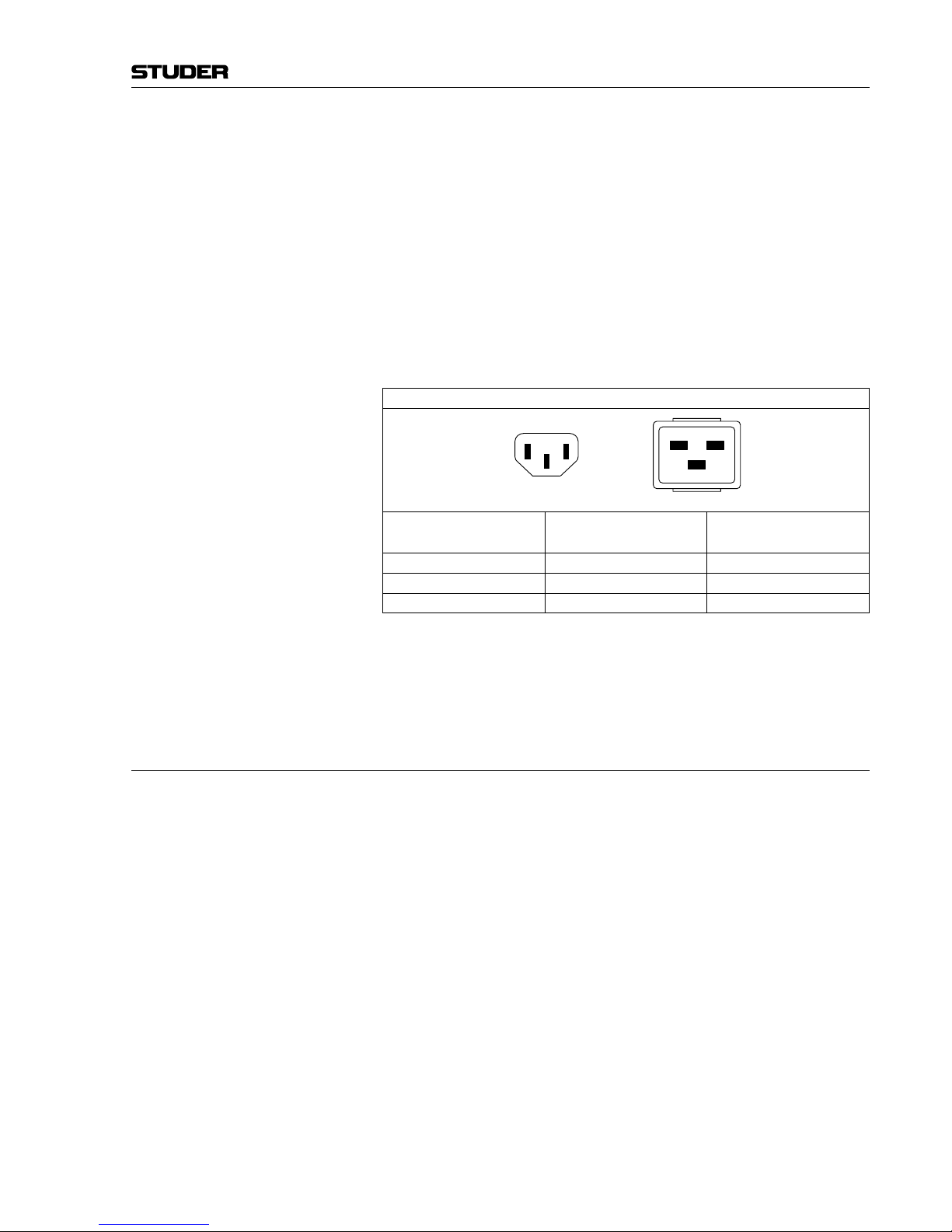
Female Plugs (IEC320), Front-Side View:
European Standard
(CENELEC)
North American Standard
(NAS)
Brown
L (Live)
Black
Blue
N (Neutral)
White
Green/Yellow
PE (Protective Earth)
Green (or Green/Yellow)
Class III Equipment (Battery Operation up to 60 VDC)
Equipment of this protection class must be earthed using the provided earth
terminal if one or more external signals are connected to the unit (see explanation at the beginning of this paragraph).
B4 Electromagnetic Compatibility (EMC)
The unit conforms to the protection requirements relevant to electromagnetic
phenomena that are listed in guidelines 89/336/EC and FCC, part 15.
• The
electromagnetic interference generated by the unit is limited in such
a way that other equipment and systems can be operated normally.
• The unit is adequately protected against electromagnetic interference so
that it can operate properly.
The unit has been tested and conforms to the EMC standards of the speci-
fied electromagnetic environment, as listed in the following declaration.
The limits of these standards ensure protection of the environment and corresponding noise immunity of the equipment with appropriate probability.
However, a professional installation and integration within the system are
imperative prerequisites for operation without EMC problems.
For this purpose, the following measures must be followed:
• Install the equipment in accordance with the operating instructions. Use
the supplied accessories.
• In the system and in the vicinity where the equipment is installed, use only
components (systems, equipment) that also fulfill the EMC standards for
the given environment.
PE
L N
IEC 320 / C19IEC 320 / C13
PE
L N
Page 8
VI
• Use a system grounding concept that satisfies the safety requirements
(class I equipment must be connected with a protective ground conductor) and that also takes into consideration the EMC requirements. When
deciding between radial, surface, or combined grounding, the advantages
and disadvantages should be carefully evaluated in each case.
• Use
shielded cables where shielding is specified. The connection of the
shield to the corresponding connector terminal or housing should have a
large surface and be corrosion-proof. Please note that a cable shield connected only single-ended can act as a transmitting or receiving antenna
within the corresponding frequency range.
• Avoid ground loops or reduce their adverse effects by keeping the loop surface as small as possible, and reduce the noise current flowing through the
loop by inserting an additional impedance (e.g. common-mode choke).
• Reduce electrostatic discharge (ESD) of persons by installing an appropriate floor covering (e.g. a carpet with permanent electrostatic filaments) and
by keeping the relative humidity above 30%. Further measures (e.g. conducting floor) are usually unnecessary and only effective if used together
with corresponding personal equipment.
• When using equipment with touch-sensitive operator controls, please take
care that the surrounding building structure allows for sufficient capacitive
coupling of the operator. This coupling can be improved by an additional,
conducting surface in the operator’s area, connected to the equipment
housing (e.g. metal foil underneath the floor covering, carpet with conductive backing).
C Maintenance
All air vents and openings for operating elements (faders, rotary knobs) must
be checked on a regular basis, and cleaned in case of dust accumulation. For
cleaning, a soft paint-brush or a vacuum cleaner is recommended.
Cleaning the surfaces of the unit is performed with a soft, dry cloth or a soft
brush.
Persistent
contamination can be treated with a cloth that is slightly humidified
with a mild cleaning solution, such as dishwashing detergent.
For cleaning display windows, commercially available computer/TV screen
cleaners are suited. Use only a slightly damp (never wet) cloth.
Never use any solvents for cleaning the exterior of the unit! Liquids must
never be sprayed or poured on directly!
F
or equipment-specific maintenance information please refer to the corre-
sponding chapter in the operating and service manuals.
D Electrostatic Discharge during Maintenance and Repair
Caution: Observe the precautions for handling devices sensitive to electrostatic dis-
charge!
Many semiconductor components are sensitive to electrostatic discharge
(ESD). The lifespan of assemblies containing such components can be drastically reduced by improper handling during maintenance and repair. Please
observe the following rules when handling ESD sensitive components:
• ESD sensitive components should only be stored and transported in the
packing material specifically provided for this purpose.
EMC / Maintenance / ESD
Page 9

VII
ESD / Repair
• When performing a repair by replacing complete assemblies, the removed
assembly must be sent back to the supplier in the same packing material
in which the replacement assembly was shipped. If this should not be the
case, any claim for a possible refund will be null and void.
• U
npacked ESD sensitive components should only be handled in ESD
protected areas (EPA, e.g. area for field service, repair or service bench)
and only be touched by persons wearing a wristlet connected to the ground
potential of the repair or service bench by a series resistor. The equipment
to be repaired or serviced as well as all tools and electrically semi-conducting work, storage, and floor mats should also be connected to this ground
potential.
• T
he terminals of ESD sensitive components must not come in uncontrolled
contact with electrostatically chargeable or metallic surfaces (voltage
puncture, discharge shock hazard).
• T
o prevent the components from undefined transient stress and possible
damage due to inadmissible voltages or compensation currents, electrical
connections should only be established or separated when the equipment
is switched off and after any capacitor charges have decayed.
E Repair
By removing housing parts or shields, energized parts may be exposed. For
this reason the following precautions must be observed:
• Maintenance may only be performed by trained personnel in accordance
with the applicable regulations.
• The equipment must be switched off and disconnected from the AC power
outlet before any housing parts are removed.
• Even if the equipment is disconnected from the power outlet, parts with
hazardous charges (e.g. capacitors, picture tubes) must not be touched until
they have been properly discharged. Do not touch hot components (power
semiconductors, heat sinks, etc.) before they have cooled off.
• If maintenance is performed on a unit that is opened while being switched
on, no un-insulated circuit components and metallic semiconductor housings must be touched, neither with bare hands nor with un-insulated
tools.
Certain components pose additional hazards:
• Explosion hazard from lithium batteries, electrolytic capacitors and power
semiconductors (Observe the component’s polarity. Do not short battery
terminals. Replace batteries only by the same type).
• Implosion hazard from evacuated display units.
• Radiation hazard from laser units (non-ionizing), picture tubes (ionizing).
• Caustic effect of display units (LCD) and components containing liquid
electrolyte.
Such components should only be handled by trained personnel who are prop-
erly protected (e.g. protection glasses, gloves).
Page 10
VIII
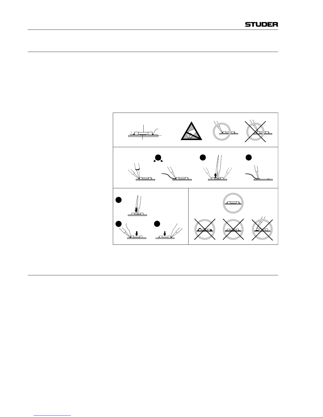
E1 SMD Components
Studer has no commercially available SMD components in stock for ser-
vice purposes. For repair, the corresponding devices have to be purchased
locally. The specifications of special components can be found in the service
manual.
SMD
components should only be replaced by skilled specialists using appropriate tools. No warranty claims will be accepted for circuit boards that have
been damaged. Proper and improper SMD soldering joints are illustrated
below.
F Disposal
Packing Materials The packing materials have been selected with environmental and disposal
issues in mind. All packing material can be recycled. Recycling packing saves
raw materials and reduces the volume of waste.
If you need to dispose of the transport packing materials, please try to use
recyclable means.
Used Equipment Used equipment contains valuable raw materials as well as materials that
must be disposed of professionally. Please return your used equipment via an
authorized specialist dealer or via the public waste disposal system, ensuring
any material that can be recycled is.
Please take care that your used equipment cannot be abused. To avoid abuse,
delete sensitive data from any data storage media. After having disconnected
your used equipment from the mains supply, make sure that the mains connector and the mains cable are made useless.
Repair / Disposal
Dismounting
Mounting Examples
Solder
SMD
Component
Copper
Track
Adhesive
Soldering Iron
Desoldering
Iron
Desolder
Wick
Heat and Remove Cleaning
Solder
Ø 0.5...0.8 mm
Heating Time < 3 s per Side
Soldering
Iron
Desolder
Wick
PCB
3
2
1
3
2
1
Page 11

IX
G Declarations of Conformity
G1 Class A Equipment - FCC Notice
This equipment has been tested and found to comply with the limits for a
Class A digital device, pursuant to Part 15 of the FCC Rules. These limits
are designed to provide a reasonable protection against harmful interference when the equipment is operated in a commercial environment. This
equipment generates, uses, and can radiate radio frequency energy and, if
not installed and used in accordance with the instruction manual, may cause
harmful
interference to radio communications. Operation of this equipment
in a residential area is likely to cause harmful interference, in which case the
user will be required to correct the interference at his own expense.
This Class A digital apparatus meets the requirements of the Canadian Inter-
ference-Causing Equipment Regulations.
C
et appareil numérique de la Classe A respecte toutes les exigences du Règle-
ment sur le matériel brouilleur du Canada.
Caution: Any changes or modifications not expressly approved by the manufacturer
could void the user’s authority to operate the equipment. Also refer to relevant
information in this manual.
Conformity
Page 12

X
Appendix 1: Air Temperature and Humidity
General
Normal operation of the unit or system is warranted under the ambient condi-
tions defined by EN 60721-3-3, set IE32, value 3K3.
T
his standard consists of an extensive catalogue of parameters, the most
important of which are: ambient temperature +5...+40 °C, relative humidity 5...85% (i.e., no formation of condensation or ice); absolute humidity
1...25 g/m³; rate of temperature change < 0.5 °C/min. These parameters are
dealt with in the following paragraphs.
Under these conditions the unit or system starts and works without any prob-
lem. Beyond these specifications, possible problems are described below.
Ambient Temperature
Units and systems by Studer are generally designed for an ambient tempera-
ture
range (i.e. temperature of the incoming air) of +5 °C to +40 °C. When
rack mounting the units, the intended air flow and herewith adequate cooling
must be provided. The following facts must be considered:
• The admissible ambient temperature range for operation of the semiconductor components is 0 °C to +70 °C (commercial temperature range for
operation).
• The air flow through the installation must provide that the outgoing air is
always cooler than 70 °C.
• Average heat increase of the cooling air shall be about 20 K, allowing for
an additional maximum 10 K increase at the hot components.
• In order to dissipate 1 kW with this admissible average heat increase, an
air flow of 2.65 m³/min is required.
Example: A rack dissipating P = 800 W requires an air flow of 0.8 * 2.65 m³/min which
corresponds to 2.12 m³/min.
• If the cooling function of the installation must be monitored (e.g. for fan
failure or illumination with spot lamps), the outgoing air temperature must
be measured directly above the modules at several places within the rack.
The trigger temperature of the sensors should be 65 °C to 70 °C.
Frost and Dew
The unsealed system parts (connector areas and semiconductor pins) allow
for a minute formation of ice or frost. However, formation of dew visible to
the naked eye will already lead to malfunctions. In practice, reliable operation
can be expected in a temperature range above –15 °C, if the following
general rule is considered for putting the cold system into operation:
If the air within the system is cooled down, the relative humidity rises. If it
reaches 100%, condensation will arise, usually in the boundary layer between
the air and a cooler surface, together with formation of ice or dew at sensitive areas of the system (contacts, IC pins, etc.). Once internal condensation
occurs, trouble-free operation cannot be guaranteed, independent of temperature.
Before putting into operation, the system must be checked for internal for-
mation of condensation or ice. Only with a minute formation of ice, direct
Appendix
Page 13
XI
evaporation (sublimation) may be expected; otherwise the system must be
heated and dried while switched off.
A system without visible internal formation of ice or condensation should be
heated up with its own heat dissipation, as homogeneously (and subsequently
as slow) as possible; the ambient temperature should then always be lower
than the one of the outgoing air.
If it is absolutely necessary to operate the cold system immediately within
warm ambient air, this air must be dehydrated. In such a case, the absolute
humidity must be so low that the relative humidity, related to the coldest
system surface, always remains below 100%.
E
nsure that the enclosed air is as dry as possible when powering off (i.e. before
switching off in winter, aerate the room with cold, dry air, and remove humid
objects such as clothes from the room).
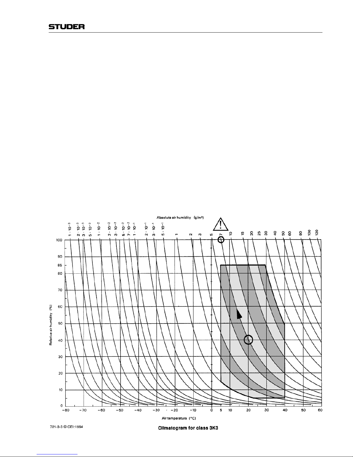
These
relationships are visible from the following climatogram. For a controlled procedure, thermometer and hygrometer as well as a thermometer
within the system will be required.
Example 1: An OB-van having an internal temperature of 20 °C and a relative humidity of
40% is switched off in the evening. If the temperature falls below +5 °C, the
relative humidity will rise to 100% (7 g/m³); dew or ice will be forming.
Example 2: An OB-van is heated up in the morning with air of 20 °C and a relative
humidity of 40%. On all parts being cooler than +5 °C, dew or ice will be
forming.
Appendix
Page 14
XII
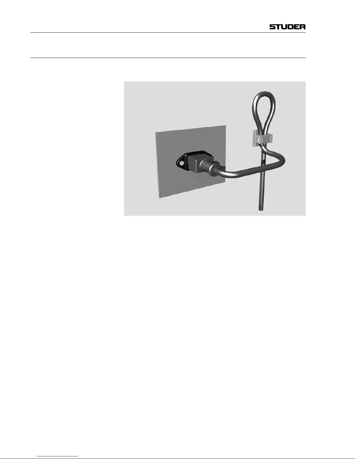
Appendix 2: Mains Connector Strain Relief
For anchoring connectors without a mechanical lock (e.g. IEC mains connec-
tors), we recommend the following arrangement:
Pr
ocedure: The cable clamp shipped with your unit is auto-adhesive. For mounting please
follow the rules below:
• The surface to be adhered to must be clean, dry, and free from grease, oil,
or other contaminants. Recommended application temperature range is
+20 °C to +40 °C.
• Remove the plastic protective backing from the rear side of the clamp
and apply it firmly to the surface at the desired position. Allow as much
time as possible for curing. The bond continues to develop for as long as
24 hours.
• For improved stability, the clamp should be fixed with a screw. For this
purpose, a self-tapping screw and an M4 bolt and nut are included.
• Place the cable into the clamp as shown in the illustration above and firmly
press down the internal top cover until the cable is fixed.
Appendix
Page 15

XIII
Appendix
Appendix 3: Software License
Use of the software is subject to the Studer Professional Audio Software
License Agreement set forth below. Using the software indicates your acceptance of this license agreement. If you do not accept these license terms, you
are not authorized to use this software.
Under the condition and within the scope of the following Terms and Con-
ditions, Studer Professional Audio GmbH (hereinafter “Studer”) grants the
right to use programs developed by Studer as well as those of third parties
which have been installed by Studer on or within its products. References
to the license programs shall be references to the newest release of a license
program installed at the Customer’s site.
Programs Covered by the Agreement
License Programs of Studer The following Terms and Conditions grant the right to use all programs of
Studer that are part of the System and/or its options at the time of its delivery
to the Customer, as well as the installation software on the original data disk
and the accompanying documentation (“License Material”). In this Agreement the word “Programs” shall have the meaning of programs and data
written in machine code.
Using
the software indicates your acceptance of this license agreement. If
you do not accept these license terms, you are not authorized to use this software.
Programs of Third Parties Programs of third parties are all programs which constitute part of the System
and/or its options at the time of delivery to the Customer but have not been
developed by Studer. The following conditions are applicable to programs of
third parties:
• The
right to use third parties’ programs is governed by the License Agreement attached hereto (if applicable), which is an integral part of this Agreement. The Customer shall sign any and all License Agreements for all
further programs of third parties installed on the system. The Customer
shall be deemed to have received all License Agreements upon delivery
of the system and/or its options.
• Studer shall accept no responsibility or liability for, and gives no warranties (express or implied) as to the programs of third parties. The Customer
waives any and all claims versus Studer for any consequential damages,
which might occur due to defects of these programs.
Right of Use
Principle Studer grants the Customer the non-exclusive right to use the License Ma-
terial in one copy on the system and/or its options as laid down by the Sales
Agreement concluded between the parties and all Terms and Conditions
which shall be deemed to form and be read and construed as part of the
Sales Agreement. This right is assignable according to the “Assignability”
paragraph hereinafter.
Customized Configurations The Customer is not entitled to alter or develop further the License Material
except within the expressly permitted configuration possibilities given by the
software installed on the system or elsewhere. All altered programs, includ-
Page 16
XIV
ing but not limited to the products altered within the permitted configuration
possibilities, are covered by this License Agreement.
Re
verse Engineering Reverse engineering is only permitted with the express consent of Studer.
The consent of Studer can be obtained but is not limited to the case in which
the interface software can not be provided by Studer. In any case Studer has
to be informed immediately upon complete or partial reverse engineering.
Copying the License Material The Customer is entitled to make one copy of all or parts of the License
Material as is necessary for the use according to this Agreement, namely for
backup purposes. The Customer shall apply the copyright of Studer found on
the License Material onto all copies made by him. Records shall be kept by
the Customer regarding the amount of copies made and their place of keeping.
The responsibility for the original program and all copies made lies with the
Customer. Studer is entitled to check these records on first request. Copies
not needed anymore have to be destroyed immediately.
Disclosure of License Material The License Material is a business secret of Studer. The Customer shall not
hand out or in any way give access to parts of or the complete License Material
to third parties nor to publish any part of the License Material without prior
written consent of Studer. The Customer shall protect the License Material
and any copies made according to the paragraph above by appropriate defense
measures against unauthorized access. This obligation of non-disclosure is a
perpetual obligation.
Third parties are entitled to have access to the License Material if they use the
License Material at the Customer’s site in compliance with this Agreement.
Under no circumstance are third parties entitled to have access to the instal-
lation software on the original data media. The Customer shall safeguard the
original data media accordingly.
Assignability The rights granted to the Customer according to this License Agreement shall
only be assignable to a third party together with the transfer of the system
and/or its options and after the prior written consent of Studer.
Rights to License Material
With the exception of the right of use granted by this License Agreement all
proprietary rights to the License Material, especially the ownership and the
intellectual property rights (such as but not limited to patents and copyright)
remain with Studer even if alterations, customized changes or amendments
have been made to the License Material.
Studer’
s proprietary rights are acknowledged by the Customer. The Customer
shall undertake no infringements and make no claims of any patent, registered
design, copyright, trade mark or trade name, or other intellectual property
right.
Warranty, Disclaimer, and Liability
F
or all issues not covered herewithin, refer to the “General Terms and Condi-
tions of Sales and Delivery” being part of the sales contract.
Appendix
Page 17

Vista 9 Digital Mixing System
Introduction 1-1
Date printed: 26.10.10
SW V4.5
CHAPTER 1
1 Introduction ..................................................................................................................................................................... 3
1.1 Operating Features ...................................................................................................................................................... 3
1.1.1 Vistonics™ .............................................................................................................................................................4
1.1.2 Momentary/Latching Keys .............................................................................................................................. 7
1.1.3 Ganging ................................................................................................................................................................. 8
1.1.4 Copy/Paste ............................................................................................................................................................. 9
1.1.5 Scrolling .............................................................................................................................................................. 10
1.1.6 FaderGlow™ ........................................................................................................................................................ 12
1.1.7 TFT Level Meters ............................................................................................................................................... 13
1.2 The Graphical Controller (GC) ................................................................................................................................. 14
1.2.1 GC Screen Examples........................................................................................................................................... 15
1.3 Channels, Routing, and Buses ..................................................................................................................................18
1.4 Processing Blocks ..................................................................................................................................................... 19
1.5 Monitoring and Communication ............................................................................................................................... 19
1.6 Automation ...............................................................................................................................................................21
1.7 Input Channel Block Diagrams................................................................................................................................. 22
Page 18

Vista 9 Digital Mixing System
1-2 Introduction
Date printed: 26.10.10
SW V4.5
Page 19

Vista 9 Digital Mixing System
Introduction 1-3
Date printed: 26.10.10
SW V4.5
1 INTRODUCTION
1.1 Operating Features
Studer Vista 9 incorporates operating features that are applicable throughout
nearly the whole console operation:
• Vistonics
™
• Momentary/Latching Key Activation
• Ganging
• Copy/paste
• Scrolling
• FaderGlow
™
• TFT screens for level metering
These operating principles are described below, they are freely combinable.
Some exceptions may occur where the combination of functions is not practical. The real speed and easiness of operation will become obvious to a sound
engineer by using and combining these operating principles in every day
life.
Page 20
Vista 9 Digital Mixing System
1-4 Introduction
Date printed: 26.10.10
SW V4.5
1.1.1 Vistonics™
Vistonics™ allows color and shape of controls to be varied according to good
ergonomic practice. A given audio function is always associated with the same
color, and a parameter is always associated with the same icon displaying
values graphically – just as or even more intuitive than an analog console.
Vistonics™ makes it possible to bring the location where you can see a value to
exactly the place where you control it. Therefore, tiring translation processes
between looking at a screen and finding the corresponding hardware control
somewhere else are not existing anymore, saving just a little time and energy
a few hundred times a day!
View = Control Location View = Control Location
Display
+ Controls
Conventional TFT Approach Vistonics Technology
Controls
Display
/
Great attention has been paid in order to make the current association clearly
visible. Color coding has been used to indicate families of audio functions
such as EQ, dynamics, etc. Consistent icons make the physical meaning of
an audio function obvious – e.g. bar graph-like icons indicate levels, time
adjustments are indicated by clock dials, etc. This way, it is easy to identify
the currently associated function even from a distance.
The Vistonics™ module consists of two main parts: 40 rotary controls with
push buttons next to each of them, as well as a touch screen area, showing
graphically the most important settings of each channel: Dynamics, EQ and
panning information. It is possible to change the association of a rotary control to audio functions either globally or locally.
Page 21
Vista 9 Digital Mixing System
Introduction 1-5
Date printed: 26.10.10
SW V4.5
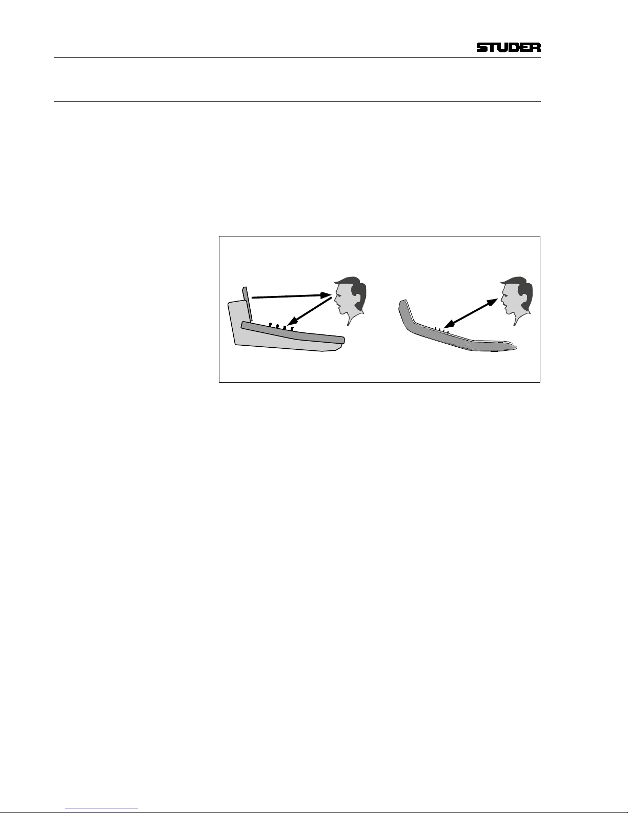
Global Views Up to four different parameters are shown in each channel strip. The same
four parameters will be shown globally on the whole console. This mode is
meant to be the ‘horizontal way of operation’, mostly used for e.g. operating
auxiliaries or input settings. The picture below shows a global AUX 1...4
view.
Global Bus Assign Overview
Page 22
Vista 9 Digital Mixing System
1-6 Introduction
Date printed: 26.10.10
SW V4.5
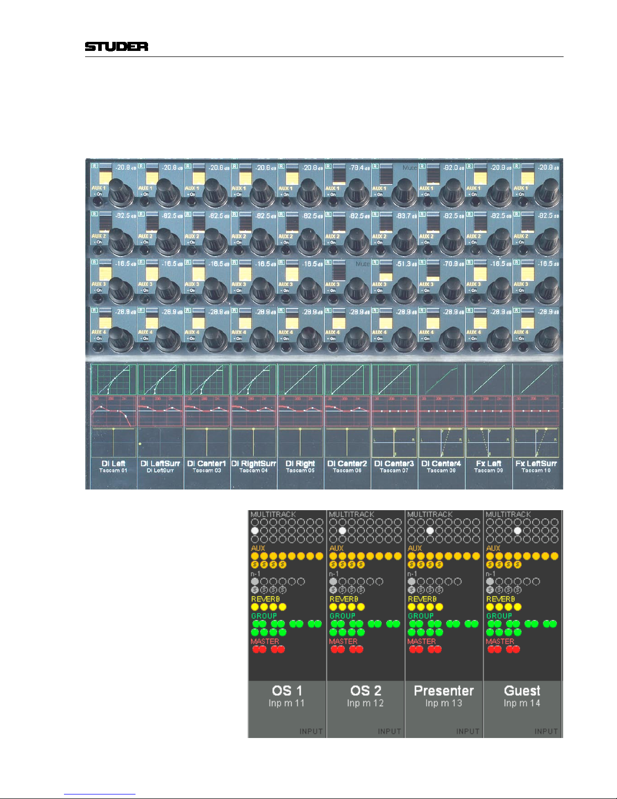
Local Views By touching the graphics shown below the Vistonics™ rotary controls, the
whole parameter set of that specific curve is displayed, also covering some
of the neighboring channel strips. It is also possible to touch any two curves
in one bay in order to display both at the same time.
The example below shows the complete dynamics section of the leftmost
channel (the small dynamics view is highlighted), overlaid to a global AUX
view.
This philosophy is completed by three hardware keys underneath the Viston-
ics
™
display, showing different combinations of parameters as well as the bus
assignment of that specific channel, covering the whole Vistonics
™
area.
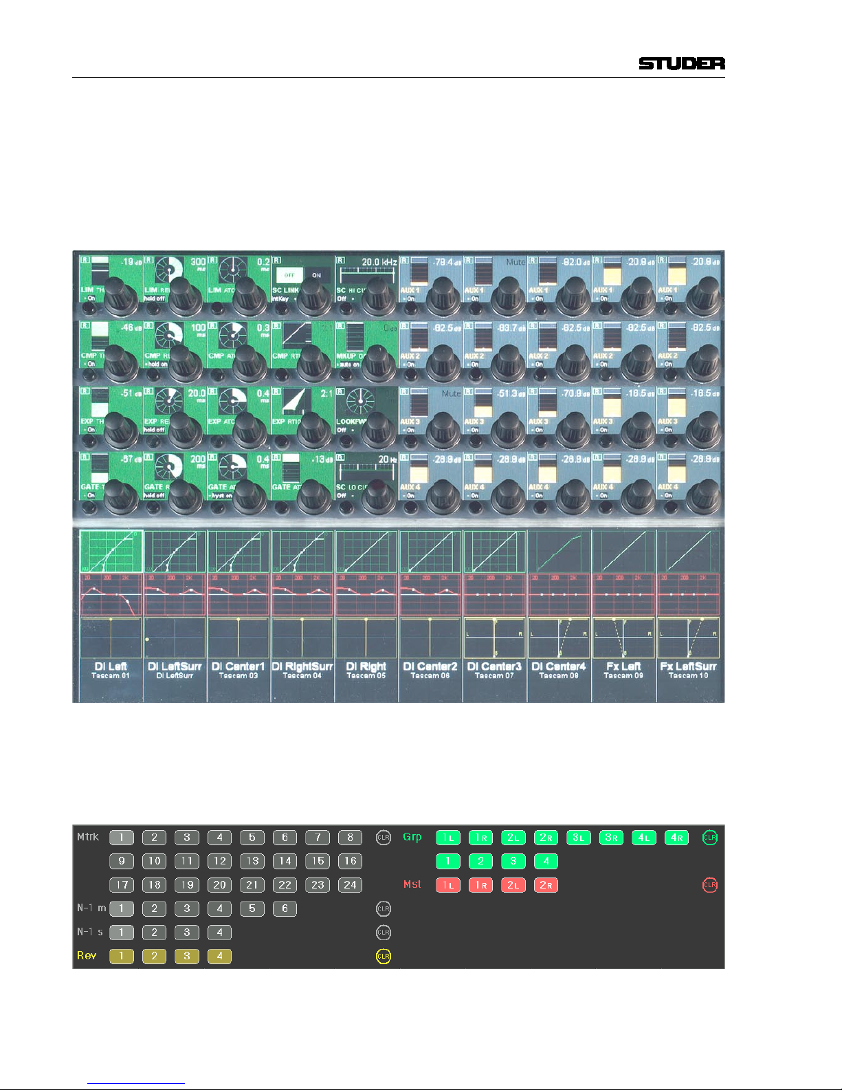
Local Bus Assign View (here, channels can directly be assigned to a bus)
Page 23

Vista 9 Digital Mixing System
Introduction 1-7
Date printed: 26.10.10
SW V4.5
1.1.2 Momentary/Latching Keys
A lot of key presses during console operation are repetitive in order to com-
pare settings or to make quick checks for monitoring purposes. The Studer
Vista console has reduced the amount of needed key presses tremendously by
incorporating a special logic for these cases: The Studer Vista control surface
distinguishes long and short key presses and reacts differently in both cases:
Pressing and holding a key will automatically reverse its activation upon
release of the key – this is, however, applied only where appropriate. All
keys featuring momentary/latching activation are labeled with a symbol
throughout this manual.
For example, holding down a MUTE key for one second will automatically un-
mute the signal again upon release. Further examples are ON/OFF switching
of audio functions (EQ, filters, dynamics), PFL/SOLO as well as most of the
monitoring functions: soloing different loudspeakers, muting loudspeakers,
selecting alternate loudspeaker sets, etc. Keeping a monitoring source key or
loudspeaker set key pressed will automatically go back to the previous selection upon key release. If you want a switch to be activated continuously, just
press the key and release it immediately, without holding.
This automatism also works on view changes: Pressing and holding an EQ
graphic will make all its parameters accessible for as long as the graphic on
the screen is being touched. However, it will disappear immediately when
the graphic is untouched. The same thing is possible for global view changes:
Quick checks of bus assignments or auxiliary levels are as fast as never
before.
This philosophy has also the advantage of not having to remember the last
settings or views. The console remembers it automatically.
Note The threshold time for the momentary/latching distinction is adjustable in the
Graphical Controller’s ‘Vista Desk Settings’ screen.
Page 24
Vista 9 Digital Mixing System
1-8 Introduction
Date printed: 26.10.10
SW V4.5
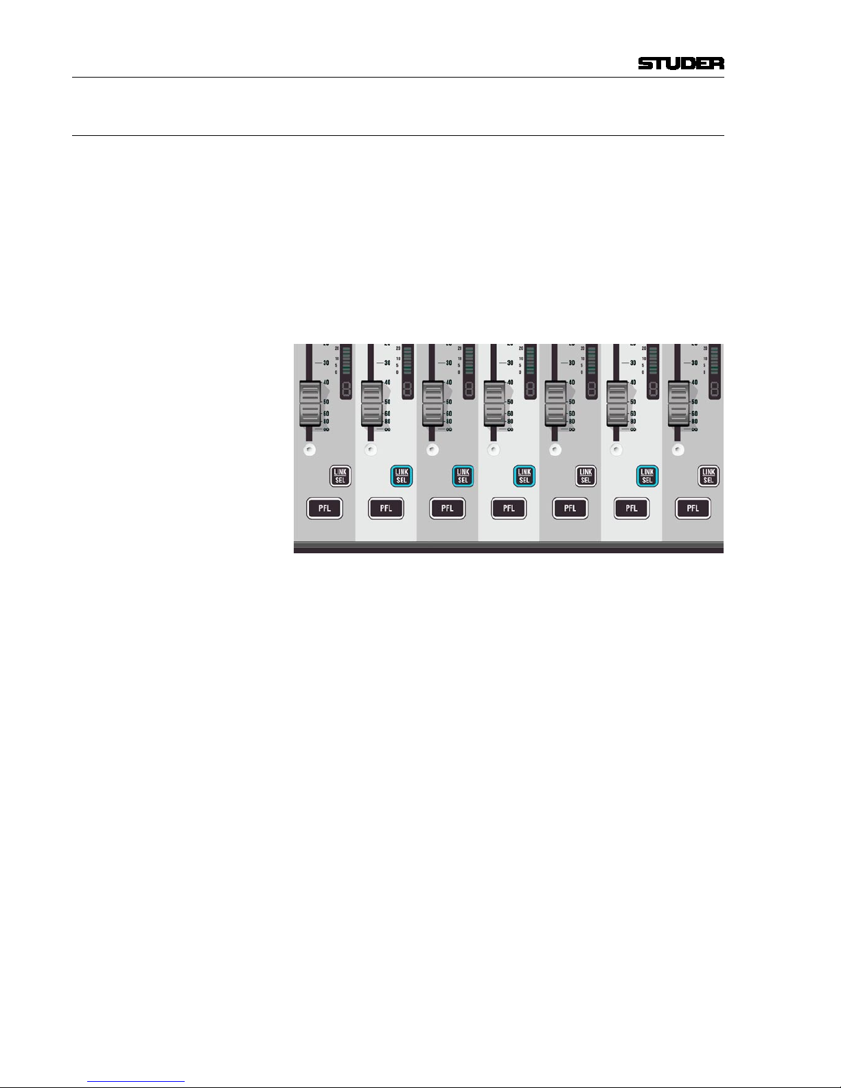
1.1.3 Ganging
On top of grouping certain channels together in a way commonly known as
VCA groups, Studer Vista has the ability to link multiple channels temporarily together and let them behave like one single channel. Such a link is called
a Gang. It co-exists with VCA style groups (Control Groups) and is only a
momentary help to influence multiple channels at the same time. A gang is
created by pressing and holding one LINK / SEL key on one channel while
the same key on a second channel gets pressed. This will link all channels
between the two. By using the MULTI SEL key it is possible to select or deselect any channels on the surface without having them next to each other.
The MULTI SEL key acts much the same as the Ctrl key on a standard PC
keyboard.
A gang is simply canceled by pressing any LINK / SEL key on the console
again. Please note that always one channel is selected.
Temporary de-activation of a gang is done by simultaneously touching identi-
cal control elements (e.g. f
ader or rotary encoder) of two channels within a
gang.
Typical Applications • Trimming of some faders or auxiliaries by changing the corresponding
control on any of the channels
• Cop
ying a certain setting to multiple channels by pasting the value to any
of the ganged channels
• Changing a bus assignment on all the ganged channels by changing it on
one of them
• Changing dynamic automation modes on the whole gang.
Basically any operation on one of the ganged channels will influence all of
them. Changing switches will overwrite the same switch on the other channels, while adjusting a audio function with a certain range will adjust all
other channels in a relative manner. Setting all channels to the same value is
accomplished by a copy/paste operation on one of the ganged channels.
Setting Up the Console
For setup application there is a fast way to link all channels of the same type
together. Pressing LINK ALL followed by pressing the LINK/SEL key of one
channel will gang all channels of that very same type together (e.g. all input
channels). The gang may exceed the visible channels and may also contain
channels in other sections. While having that gang active, you may setup your
console within seconds: Changing bus assignment, clearing one channel or
copy/paste certain values to any of these channels.
Page 25
Vista 9 Digital Mixing System
Introduction 1-9
Date printed: 26.10.10
SW V4.5
1.1.4 Copy/Paste
Copying certain audio settings across the console is made very fast and easy:
Each channel strip hosts copy/paste keys dedicated to a certain audio function, as EQ, dynamics, etc. Pressing one of these keys will make it fully lit,
while all possible destination channels (channels that also have this same
audio function) will show up half-lit. Selecting anyone of them will paste the
value into that channel. It is possible to paste a value to multiple channels
with the help of the MULTI SEL key or by creating a gang. However, there is
a shortcut to paste a value to multiple channels located next to each other:
Press and hold the (Cop
y/Paste) key of the first channel while pressing
the (Cop
y/Paste) key on the last channel. This will paste the value to all
channels in between.
There is also a special A (Copy/Paste All) key to copy a whole channel
including bus assignment, as well as a
(Undo/Redo) key to undo the last
paste or clear function on each channel separately. Pressing this key after an
undo operation again will redo the last copy.
Note The
(Undo/Redo) key can be used momentarily (long press) in order to
compare settings on a channel:
1 Press the (Copy/Paste) key twice in order to ‘memorize’ the current
setting (i.e., by pasting it to itself)
2 Adjust the audio function to an alternative setting
3 Press (Undo/Redo) multiple times (either short or long) in order to
compare the two settings.
Half-Lit Keys Whenever the console is waiting for a key press in order to finish a function,
it will illuminate all possible keys by half. This is a guide for the user – so
he can select one of these keys, or reverse the function by pressing the first
(fully lit) key again. A timeout applies if none of the half-lit keys are pressed
within a given time frame. Timeout duration is adjustable in the “Vista Desk
Settings” menu on the GC.
Examples:
(Copy/Paste) > (Copy/Paste),
LINK ALL
> LINK/SEL,
Setup of control groups, etc.
Page 26
Vista 9 Digital Mixing System
1-10 Introduction
Date printed: 26.10.10
SW V4.5
1.1.5 Scrolling
Most Vista installations will have more channels available in the DSP core
than there are physical faders on the console surface. Most manufacturers deal
with that fact by introducing ‘layers’. The console surface can be switched
in order to show the different layers, all of which making all DSP channels
available to the user. The Vista operating philosophy has modified this concept: Rather than thinking of layers sitting on top of each other, we think
of the layers being arranged on a horizontal line. The ‘Layer’ is now called
‘Section’. The six sections are next to each other on an imaginary horizontal
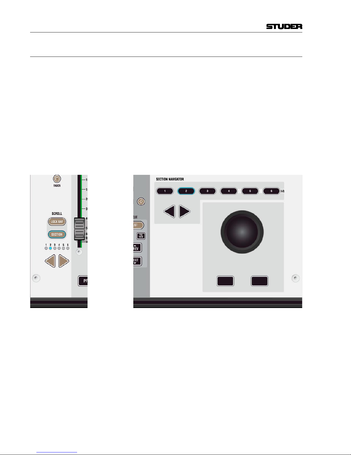
line, as indicated by the ‘Section Navigator’ keys in the control bay.
As long as the user wants to switch to a specific section, there is no difference
in operation to the ‘layer’ concept. Changing to another section is accomplished by pressing one of the corresponding keys in the SEcTIoN NAvIgATor
area of the control bay (belo
w right), or by pressing the arrow keys located
in each fader bay with ScroLL: SEcTIoN set to ON (below left).
Information on which section is currently displayed is given by the lit keys
(Control Bay) or the LEDs representing the different sections (Fader Bay).
Looking at the Graphical Controller with the ‘strip setup’ screen in the foreground will also indicate the currently displayed section by putting a dark
background to the displayed channels.
The Difference from the Layer Concept
Rather than just switching to another section, it is possible to scroll through
the sections by pressing any arrow key (for this purpose, ScroLL: SEcTIoN
has to be OFF on the fader bays). This will make the physical surface scroll
through all sections with a step size of one bay (10 channels). It is therefore
possible to move any channels close to the position of the operator, allowing
him to stay in the ‘sweet spot’ at all times. This concept can also be imagined
like moving a chair in front of an analog console. On Studer Vista, you move
the surface of an imaginary console six times larger than the physical console.
Page 27
Vista 9 Digital Mixing System
Introduction 1-11
Date printed: 26.10.10
SW V4.5
Which DSP channel is shown where is defined in the ‘strip setup’ dialog in
the Graphical Controller (refer to chapter 4.4.7).
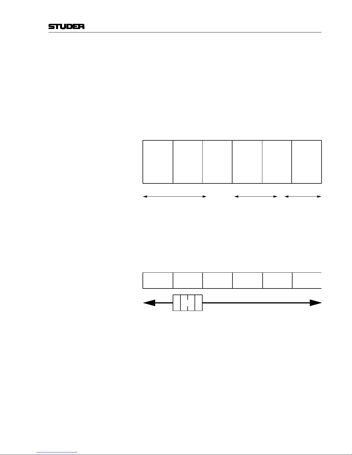
Desk Navigation Example Let’s assume a desk with 30 faders (between 20 and 70 possible in steps of
10). Since the desk can jump to six sections, this user can operate up to 6 × 30
DSP channels. Please note that it is possible to have the same DSP channel
visible in multiple places within the six sections.
Step 1 The user defines the order of the 180 DSP channels in the strip setup dialog
box in the GC. There he will find six empty sections with 30 placeholders,
each for a channel assignment.
The definition will most likely be made in such a way that the user starts with
a new section when he starts with new channel type (as shown below).
Section
1
(30 Channel Strips
to Occupy)
Section
2
Section
3
Section
4
Section
5
Section
6
(30 Channel Strips
to Occupy)
(30 Channel Strips
to Occupy)
(30 Channel Strips
to Occupy)
(30 Channel Strips
to Occupy)
(30 Channel Strips
to Occupy)
User occupies 70 Placeholders
with DSP Channels
‘Input Mono 1...70’
User occupies 48 Placeholders
with DSP Channels
‘Track Return 1...48’
42 Places with
DSP Channels
‘AUX Send’, ‘CGM’,
‘Master Outputs’
Step 2 The user can now navigate through the ‘virtual surface’ (6 sections wide) in
two ways: Either he jumps to a specific section by pressing the corresponding
key in the control bay, or he scrolls from the present position to the destination
by pressing one of the arrow keys (< and >) in any of the bays. Pressing one
of these arrow keys will virtually move the physical surface in front of the
total console (6 sections) by one bay (10 faders) at a time in the corresponding
direction (like moving a chair in front of a huge console).
Section
1
Section
2
Section
3
Section
4
Section
5
Section
6
Desk
The arrow keys are located in every bay, and they all have the same function-
ality. This prevents the user from having to move to the center of the console
for navigation.
Locking a Bay It is possible to prevent one or more bays from scrolling by switching the
ScroLL: LocK BAY key on the corresponding bay ON. This will make that
bay isolated from the remaining sections. It doesn’t only lock from scroll-
ing, but also all global view changes on the surface will not influence locked
bays. However, it is possible to change views on a locked bay by operating its
gLoBAL vIEW keys. These will now only influence the locked bay. A locked
bay is strictly isolated from view changes and will operate independently.
Please note that it is also possible to scroll a locked bay independently by
using the arrow keys on that specific bay.
It is possible as well to lock multiple bays at a time by pressing and holding
the first ScroLL: LocK BAY key and pressing a second ScroLL: LocK BAY
Page 28
Vista 9 Digital Mixing System
1-12 Introduction
Date printed: 26.10.10
SW V4.5
key on a different bay; this will lock all bays in between and form a ‘lock
group’. Multiple bays within a lock group will scroll at a time and perform
common global view changes. In this way it is easy to split the desk for twooperator use.
Scrolling a Locked Bay by One Section
When both the ScroLL: SEcTIoN and the ScroLL: LocK BAY keys are ON
on a fader bay, this is a special case. When pressing one of the arrow keys on
that specific bay, the display of channels will jump by exactly one section.
This function becomes very obvious when looking at the dark background
indication on the Graphical Controller. This operation mode might be useful
for operators who want to change to a different section with a locked bay.
1.1.6 FaderGlow
™
During a hectic live production, FaderGlow™ provides the operator with an
instant overview of the console status by illuminating each fader in one of
eight freely-assignable colours.
Now the operator can mark individual, important channels such as present-
ers, main talents and other ‘must-never-lose-their-signal’ channels. Once the
important channel is colored, it can be found within a fraction of a second,
even after mixing on a different layer and coming back to a channel layout
that may not have been on the surface for some time. Moreover, FaderGlow
™
allows the operator colouring entire channel groups (such as ‘band’, ‘guest’,
‘ambience’, ‘string section’, ‘rhythm section’ channels), in order to distinguish them easier and locate them faster. One of eight different colours can
be assigned to any channel strip.
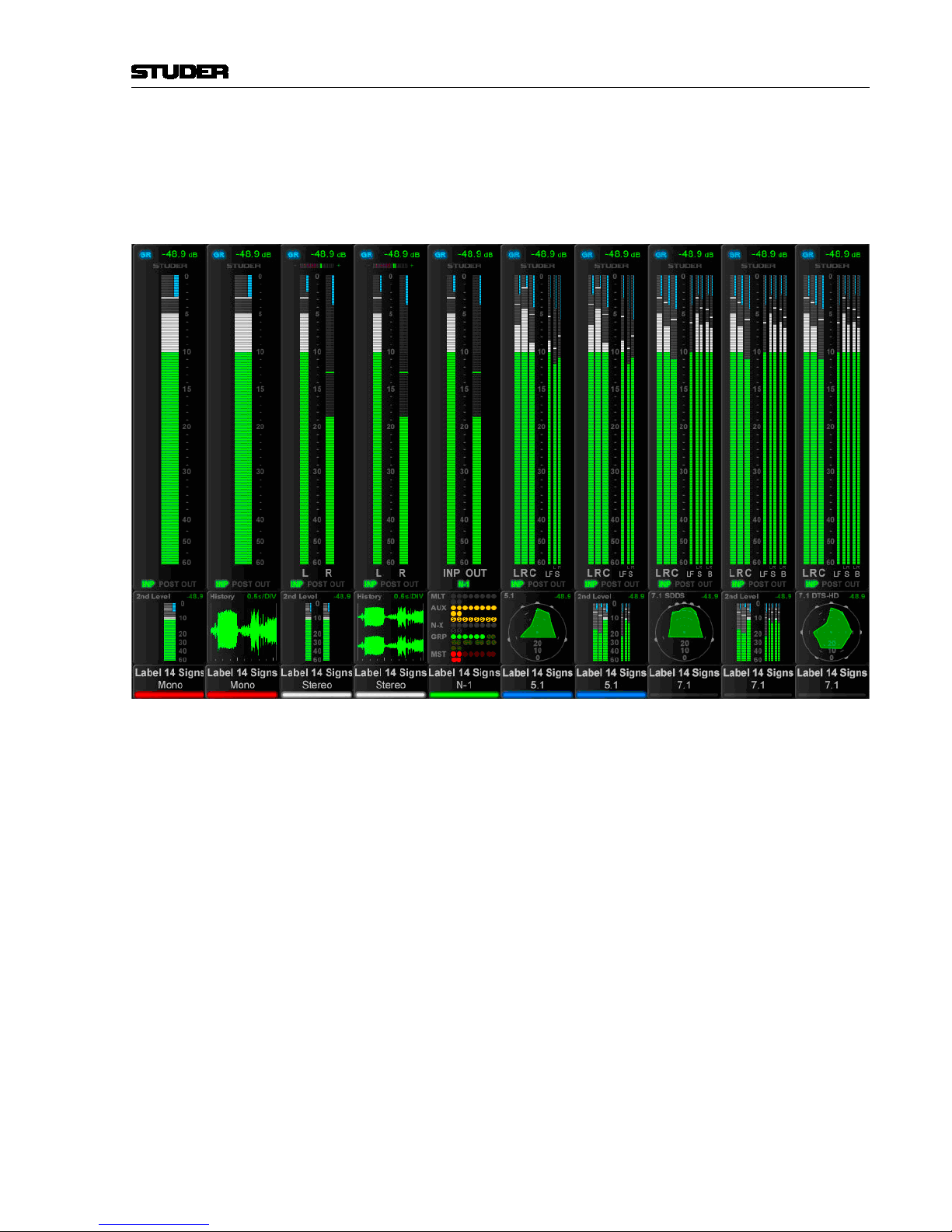
1.1.7 TFT Level Meters
TFT screens allow displaying all sorts of data, for example the metering.
For all possible channel types the metering has to go with it – from mono
over stereo and 5.1 to 7.1, always in the same space. Priority was to have as
large a bar graph meter as possible. In order to bring in more information, a
lower area is configurable and enables different options, depending on the
channel type. It can bring a surround image view or what is called the history
diagram of incoming or outgoing signal waveforms. This shows the history
of the signal and makes it easy to spot anomalies in the audio signal, such
as overloads or signal loss. When focusing on some important channels, one
might miss what’s going on somewhere else. If suddenly hearing something
strange, with the history feature a quick look across the console is sufficient
to see what has happened. Another option in the lower portion of the TFTs is a
bus assignment view, giving an overview of the channel’s current bus assignment, e.g. on a single channel where bus assignment is changed frequently.
The control bay metering differs from the meter screen on the fader bays; it is
mainly made to show output channels. Different meter views are available for
this screen. It can be switched to a predefined meter view to see all auxiliary
outputs. Or to all groups, or all programme masters, direct outs, bus outputs,
N–1s, matrix channels, etc. In addition there are user pages assignable to
Page 29
Vista 9 Digital Mixing System
Introduction 1-13
Date printed: 26.10.10
SW V4.5
whatever is desired via the strip set-up. There are four configurable user page
pages, one with ten slots in one row, one with 20 slots in two rows, and two
with 40 half-width slots in two rows. So if calling up page four, there are 40
meters, and they can be virtually anything. The two meter slots at the right
of the control bay TFT screen continuously show PFL and CR levels.
The illustration above is an example of a meter screen, with mono, stereo and
surround channels and different views in the lower area – such as metering of
the L2 channel, history, bus assignment and surround view. Further information is displayed as well, such as fader glow color, gain reduction, correlation
(for stereo signals) or surround signal type.
Page 30

Vista 9 Digital Mixing System
1-14 Introduction
Date printed: 26.10.10
SW V4.5
1.2 The Graphical Controller (GC)
An important feature of the Vista Digital Mixing System is the Graphical Con-
troller, also referred to as ‘GC’. The Graphical Controller program is used for
operating all mixing console functions that extend console’s functionality.
Specifically, the Graphical Controller’s extended functions include:
• General and channel-specific router control (defining the order of processing elements, e.g. EQ or dynamics libraries, within a channel)
• Recall and management of snapshots and cue points
• Saving of desk clipboards
• Assignment of the DSP channels to the fader strips
• Tone generator and metering control
• Control group and linkage control
• Production and Title management
• System administration
Various display windows and dialog boxes logically group the individual
functions. Visual elements are optimized for simple and intuitive operation.
With the help of an easy-to-understand General Patch page, the setup of
router cross points is dramatically simplified, even for large mixing console
configurations. Via a Snapshot window, all mixing console parameters can be
stored and recalled using mouse clicks. Some of the most important functions
are also available as dedicated keys on Vista’s control bay.
The concept of overall system configurability has been also adopted within
the Graphical Controller application. Since most functions are arranged in
overlapping windows of changeable sizes, users can set up their work environment to suit their specific requirements for each recording or production
session. These settings can be saved and recalled at any time, allowing for
fast and application-oriented operation of the Vista system.
Page 31

Vista 9 Digital Mixing System
Introduction 1-15
Date printed: 26.10.10
SW V4.5
1.2.1 GC Screen Examples
Internal Routing Matrix Control The Channel Patch screen is an audio path-oriented view for controlling the
routing of a particular channel, and is used to set up the sequence of channel
processing blocks (EQ, Insert, Delay, etc.) and metering locations within the
signal path, as well as defining the direct out signal. This screen also displays
the connections made to the channel’s various inputs and outputs. By double
clicking on one of these display boxes the system will go directly to the
associated connection in the General Patch. The Channel Patch also includes
labeling and dynamics link facilities.
Page 32

Vista 9 Digital Mixing System
1-16 Introduction
Date printed: 26.10.10
SW V4.5
Within the General Patch window, the various cross point routing of sources
and targets (destinations) is displayed. For example, it will show which audio
signals (AES/EBU in, Direct outs, etc.) connected to the DSP sections are
assigned to the corresponding channels and outputs (Input channel, MADI out
etc.). These connections are stored within Snapshots and Presets. The sources
and targets can be identified by Fixed, Device, Inherited, or User labels.
Page 33

Vista 9 Digital Mixing System
Introduction 1-17
Date printed: 26.10.10
SW V4.5
Snapshot Functions Display and control of snapshot settings (in other words, complete ‘pictures’
of the operating desk’s controls and of the console’s internal settings) and
factory/user presets provide basic working templates.
Control of snapshot/preset filters and channel protection is achieved via
separate windows:
Page 34

Vista 9 Digital Mixing System
1-18 Introduction
Date printed: 26.10.10
SW V4.5
1.3 Channels, Routing, and Buses
Processing blocks, such as equalizer, dynamics, delay, etc., can be configured
for all channel types.
Input Channels Vista’s digital routing matrix is located between the console’s physical inputs
and the actual DSP channels. This topology means that the physical analog
and digital inputs can be assigned to any console channel via the General
Patch page on the Graphical Controller. The patch setup forms part of each
individual snapshot, and can be saved, updated and recalled within the Snapshot/Preset system.
Output Channels This also applies to the outputs. On the General Patch page, each channel’s
output can be selected and sent to any analog or digital output destination.
Auxiliaries The number of stereo or mono AUX sends is fully configurable. The users
can establish the number and type of AUX sends they would like to use. The
AUX master channel can be equipped with the same selection of processing
blocks such as equalizer, dynamics, delay, and more.
Clean-Feeds/Mix-Minus (N–1/N–X) Clean-Feeds/Mix-Minus or N–1/N–X buses can be set up in stereo or mono,
and are configurable in number.
Multi-track and Group Routing Full multi-track and group routing can be configured.
Solo Modes Each channel features a Solo and a PFL Switch. Depending upon the mode
selected within the Control Bay the SOLO key is active as SOLO or Solo-InPlace. Clearing these buttons can be achieved by opening the corresponding
fader in case ‘PFL BC’ (Broadcast) is active. A very handy PFL/Solo Reset
is provided to disengage any solos regardless of where they are engaged on
the console. This eliminates the need to ‘search’ for solos with large console
configurations. A key to define certain channels to be safe from being muted
in ‘Solo-In-Place’ mode is also provided. This set will be stored with each
title.
Page 35

Vista 9 Digital Mixing System
Introduction 1-19
Date printed: 26.10.10
SW V4.5
1.4 Processing Blocks
Equalizer Four fully parametric bands are provided on the Vista. Each band, which
can be switched in and out independently, extends from 20 Hz to 20 kHz,
with a ±18 dB gain range. The EQ features a psycho-acoustically corrected
frequency response for high frequencies, similar to well-known analog EQ
designs. The two mid-bands can be switched between constant-Q and constant-range modes. The high and low frequency bands can be switched to
shelving mode. A second EQ type is available (defined in the Configuration
Tool), which features an additional Notch filter.
Filter Low-cut and high-cut filters are provided, with cutoff frequencies that are
variable between 20 Hz and 20 kHz, and slope selections of 12, 18, or 24 dB/
octave.
In addition, an analog low-cut filter with a cutoff frequency of 75 Hz and a
slope of 12 dB/octave is available in the D21m Mic/Line preamplifier.
Dynamics The Vista standard dynamics processing consists of four parts:
Limiter, Compressor, Expander, and Gate.
To avoid pumping and modulation, the dynamics processing sections feature
high sampling rate transient detection. Distortion artifacts are minimized
through selectable, program-dependent attack and release times. The Vista’s
dynamics feature a side-chain input that can be used with or without HP/LP
filters. A unique ‘look forward’ function is also featured. If desired, this
allows the entire transient portion of a waveform to be affected when using
the limiter/compressor or to be passed when the expander/gate is used.
Sometimes the dynamics processing can be utilized in a more pronounced
way, i.e., as an effect itself. For this purpose the ‘vintage dynamics’ was created. It is targeted to be flexible enough for different types of sound coloration
including extreme and unusual settings, but does not feature a dedicated
limiter.
Selection between the standard or vintage dynamics section can be made per
input channel during configuration of the console.
Soft Clip In addition, a soft clip function can be activated in the D21m Mic/Line pre-
amplifier.
1.5 Monitoring and Communication
Monitoring The Control Room (CR) monitoring section provides control of up to three
different speaker systems (two multi-channel and one two-channel stereo)
and 32 source selectors. All internal digital sources can be assigned to any of
the source selector keys. A headphone socket is also supplied for use within
the control room.
The Studio Monitor is configurable in the same way as the CR monitor sec-
tion. T
wo stereo loudspeaker pairs are supported.
Talkback An extensive talkback system is implemented within the Vista. The talkback
source can be either the desk-operator microphone or an external producer
microphone. Several destinations, such as buses, direct outputs, auxiliaries,
groups, and master outputs are available block.
Page 36

Vista 9 Digital Mixing System
1-20 Introduction
Date printed: 26.10.10
SW V4.5
Each channel is fitted with a talkback key that activates talkback to the direct
output of the corresponding channel and, if the channel is an N–1 owner, to
the N–1 output.
For details see the talkback and signaling block diagram below.
Control Room
Studio A
Talk to
CR
Ret 1
Ext 1
Studio MonitorA
TB only
PFL/TB Out
CR Monitor
Signaling Keys
Talk to
Aux1
Talk to
Aux2
Talk to
Aux3
Talk to
Aux4
Talk to
Aux1
Talk to
Aux2
Talk to
Ext1
Talk to
Ext2
Talk to
Aux3
Talk to
Aux4
Talk to
preselected
Talk to
preselected
Talk to
Studio
B
e.g.Speaker
GPI 2
GPI 4
GPI 5
GPO 3
GPO 2
GPI 1
Foot Switch
GPI 7 GPI 8 GPI 9 GPI 10 GPI 11
e.g.Intercom
Ext 3
(Line level) (Line level)
(always on)
Vista9 Desk
Mic "TB2"
TB Mic
GPO 1
Ext Location 1
Producer
( to PFL Speaker)
Studio B
Talk to
CR
Ret 2
Ext 2
Studio Monitor B
GPI 3
Ext Location 2
( to PFL Speaker)
Talk to
Studio
A
GPI 6
GPI X
Talk
to
ChanOut
Grp01
Talk
to
ChanOut
Grp N
Channel
Mute
Grp01
Channel
Mute
Grp N
Talk to
EXT1
Talk to
EXT2
GPI13
GPI12
GPI X
GPI X
GPI X GPI X
GPI X
GPI X
Live
GPI X
GPO 4
GPO X
GPO X
GPI X
GPI X
GPO X
GPO X
e.g.Speaker
GPO 6
GPO X
TB Keys
GPO 5
Legend :
GPI 1
GPO 2
GPI X
= GPI already configured in .ini files
= GPO already configured in .ini files
= GPI prepared to use, but not
assigned to signaling card.
This can be configured in .ini files
GPO X
= GPO prepared to use, but not
assigned to signaling card.
This can be configured in .ini files
Desk Operator
GPO X
Producer Area (either in control room or in another room)
Studio A Studio B
Red
Light
SIG1
SIG2
Talk
Red
Light
SIG1
SIG2
Talk
20.09.2010 wp
Talkback and signaling blockdiagram using D21m GPIO cards
Relations :
Dim CR and PFL if: Anytalk in Desk OR ( )Anytalk Producer AND Producer located in CR [DimLock is activated]
Dim StudioA if: Ret1 Talk to CR AND Ret1 located in Studio [DimLock is activated]
Dim StudioB if: Ret2 Talk to CR AND Ret2 located in Studio [DimLock is activated]
Cut StudioA if: (Faderstart of source which is assigned to StudioA) OR (StudioA is OnAir)
Cut StudioB if: (Faderstart of source which is assigned to StudioB) OR (StudioB is OnAir)
Cut Ext1 if: StudioA Cut AND Ret1 located in Studio
Cut Ext2 if: StudioB Cut AND Ret2 located in Studio
Sig1 LED StudioA = Sig1OutStudioA OR Sig1InStudioA
Sig2 LED StudioA = Sig2OutStudioA OR Sig2InStudioA
RedLight StudioA
=
StudioA Cut OR Red lightStudioA manual
TalkLED StudioA = DeskTalktoStudioA OR Ret1TalktoCR
Sig1 LED StudioB = Sig1OutStudioB OR Sig1InStudioB
Sig2 LED StudioB = Sig2OutStudioB OR Sig2InStudioB
RedLight StudioB = StudioB Cut OR RedlightStudioB manual
TalkLED StudioB = DeskTalktoStudioB OR Ret2TalktoCR
OnAirMode = OnAirKey OR GPI
Page 37

Vista 9 Digital Mixing System
Introduction 1-21
Date printed: 26.10.10
SW V4.5
1.6 Automation
Static Automation Snapshots An unlimited number of snapshots can be captured, stored, and recalled
for each Project Title. All control parameters of the console are stored in
the snapshots. When a snapshot is recalled, the console typically requires
120 ms to fully reset itself. Snapshots recalls can be done with snapshot filters active, protecting certain console parameters from being changed by the
recall. Extensive editing functions allow modifying snapshots after or during
a live show. Besides absolute protection of certain parameters it is possible to
trim parameters relative to their stored values rather then letting them totally
unmodified. Recalling a preset however, will ignore any snapshot filters
which may be active and bring the console into a defined audio state.
Copy & Paste Clipboard The Vista System supports copy and paste of some or all channel settings to
one or more other channels. This ability streamlines the set-up of the console
when an operator is starting from scratch with a new layout. However, if starting from a clean slate is desired, clearing all or some of the parameters
Dynamic Automation Each audio parameter of the Vista mixing console can be stored and recalled
dynamically against timecode information.
Such enormous versatility can be accompanied, of course, by a certain op-
eration complexity. For this reason, all operator controls capable of being
automated are touch-sensitive.
Please refer to chapter 5 for a complete description.
Page 38

Vista 9 Digital Mixing System
1-22 Introduction
Date printed: 26.10.10
SW V4.5
1.7 Input Channel Block Diagrams
Block Diagram of a Typical Mono Input Channel:
Please note that,
essentially, all
channel types
have the same
structure,
regardless
of the type
(input, AUX,
group, master,
etc.)
VSP
L/R PAN
TALKBACK
PREAMP
CTRL
EQ / +
NOTCH
INSERT
PHASE
(Mono)
IN 1
IN 2
GEN (Generator)
INSERT RETURN
INP
SEL
INPUTS
GR Meter
SC LINK INPUT
Input Mode Section
FILTER
DC
REJECT
GAIN
Input Process Section
SIDECHAIN IN
DIGITAL
PATCH
DIGITAL
PATCH
DIGITAL
PATCH
DIGITAL
PATCH
DIGITAL
PATCH
DYN /
V. DYN
FADER
MUTE
DELAY
PF AF
CHANNEL PATCH MATRIX
PF AF
PATCH
DIGITAL
DIGITAL
PATCH
MULTI-TRACK
Buses
MULTI-TRACK
Enh. Buses
DIR OUT
AF
PF
AINP
TB
DIRECT OUTPUT
TB
METER
SELECT
DO
AF
AINP
METER
DATA
N–X
Buses
N–1
Buses
PFL
1-8
1-8
1-8
1-8
1-8
1-8
1-8
STEREO AUX
Buses
GROUP
Buses
MASTER
Buses
MONO AUX
Buses
MPX
Buses
INSERT SEND
CHANNEL
OUTPUTS
PFL Bus
SOLO Bus
SC LINK OUTPUT
L
R
PAN
PF
AF
PF
AF
PF
AF
MONO AUX
MPX
PF
AF
MTR ENH.
STEREO AUX
MULTI-
FMT
PAN
Page 39

Vista 9 Digital Mixing System
Introduction 1-23
Date printed: 26.10.10
SW V4.5
Block Diagram of a Typical Stereo Input Channel:
Please note that,
essentially, all
channel types
have the same
structure,
regardless
of the type
(input, AUX,
group, master, etc.)
TALKBACK
PREAMP
CTRL
EQ / +
NOTCH
INSERT
MS / XY PHASE
MATRIX (Stereo)
STEREO
BAL
MODE
IN 1
IN 2
GEN (Generator)
INSERT RETURN
INP
SEL
INPUTS
GR Meter
SC LINK INPUT
Input Mode Section
FILTER
DC
REJECT
GAIN
Input Process Section
SIDECHAIN IN
DIGITAL
PATCH
DIGITAL
PATCH
DIGITAL
PATCH
DIGITAL
PATCH
DIGITAL
PATCH
DYN /
V. DYN
FADER
MUTE
DELAY
PF AF
CHANNEL PATCH MATRIX
PF AF
PATCH
DIGITAL
DIGITAL
PATCH
L
R
MULTI-TRACK
Buses
MULTI-TRACK
Enh. Buses
DIR OUT
AF
PF
AINP
TB
DIRECT OUTPUT
TB
METER
SELECT
DO
AF
AINP
METER
DATA
N–X
Buses
N–1
Buses
PFL
1-6
6
1-6
1-6
1-6
1-6
1-6
STEREO AUX
Buses
GROUP
Buses
MASTER
Buses
MONO AUX
Buses
MPX
Buses
INSERT SEND
CHANNEL
OUTPUTS
PFL Bus
SOLO Bus
SC LINK OUTPUT
L
R
PAN
PF
AF
PF
AF
PF
AF
MONO AUX
MPX
PF
AF
MTR ENH.
STEREO AUX
PAN /
BAL
UPMIX
OUTPUT
WIDTH
Page 40

Vista 9 Digital Mixing System
1-24 Introduction
Date printed: 26.10.10
SW V4.5
Block Diagram of a Typical 5.1 Input Channel:
Please note that,
essentially, all
channel types
have the same
structure,
regardless
of the type
(input, AUX,
group, master, etc.)
TALKBACK
PREAMP
CTRL
EQ / +
NOTCH
INSERT
5.1
MODE
PAN-
ARND
IN 1
IN 2
GEN (Generator)
INSERT RETURN
INP
SEL
INPUTS
GR Meter
SC LINK INPUT
Input Mode Section
FILTER
DC
REJECT
GAIN
Input Process Section
SIDECHAIN IN
DIGITAL
PATCH
DIGITAL
PATCH
DIGITAL
PATCH
DIGITAL
PATCH
DIGITAL
PATCH
DYN /
V. DYN
FADER
DOWN
MIX
MUTE
DELAY
PF AF
CHANNEL PATCH MATRIX
PF AF
PATCH
DIGITAL
DIGITAL
PATCH
MULTI-TRACK
Buses
MULTI-TRACK
Enh. Buses
DIR OUT
AF
PF
AINP
TB
DIRECT OUTPUT
TB
METER
SELECT
DO
AF
AINP
METER
DATA
N–X
Buses
N–1
Buses
PFL
6
6
6
6 6 6 6
6 6 6 6 6
6
6 6 6
6 6
6 6
6 6
6
6
666
6 6
6
6
6
6
6
6
6
6
6
6
6
6
6
6
STEREO AUX
Buses
GROUP
Buses
MASTER
Buses
MONO AUX
Buses
MPX
Buses
INSERT SEND
CHANNEL
OUTPUTS
PFL Bus
SOLO Bus
SC LINK OUTPUT
L
R
PAN
PF
AF
PF
AF
PF
AF
MONO AUX
MPX
PF
AF
MTR ENH.
STEREO AUX
Page 41

Desk Operation 2-1
CHAPTER 2
2 Desk Operation ................................................................................................................................................................ 3
2.1 Fader Bay Overview ................................................................................................................................................... 4
2.2 Fader Bay Details ........................................................................................................................................................ 4
2.2.1 Area 1 – Channel Metering ................................................................................................................................... 5
2.2.2 Area 2 – Channel Control....................................................................................................................................... 5
2.2.3 Area 3a – Channel Control ..................................................................................................................................... 6
2.2.4 Area 3b – Faders .................................................................................................................................................... 8
2.2.5 Area 4 – Vistonics™ ............................................................................................................................................ 10
2.2.6 Areas 5a, 5b – Channel Selection......................................................................................................................... 13
2.2.7 Area 6 – Desk Scrolling ....................................................................................................................................... 14
2.3 Control Bay Overview .............................................................................................................................................. 15
2.4 Control Bay Details .................................................................................................................................................. 16
2.4.1 Area 1 – System Power On/Off ............................................................................................................................ 16
2.4.2 Areas 1 and 2 – Control Bay Metering ............................................................................................................... 17
2.4.3 Area 3 – Machine Control Panel (Optional) ........................................................................................................18
2.4.4 Area 4 – Monitoring Source Selector ................................................................................................................... 20
2.4.5 Area 5 – CR (Control Room) Monitoring ........................................................................................................... 21
2.4.6 Area 6 – Studio Monitoring ................................................................................................................................ 23
2.4.7 Area 7 – Talkback / Headphones Control ............................................................................................................ 24
2.4.8 Area 8 – Dynamic Automation / Static Automation ............................................................................................ 26
2.4.9 Area 9 – Mute Group / Control Group / Conference Setup ................................................................................ 30
2.4.10 Area 10 – Control Bay Vistonics™ ...................................................................................................................... 31
2.4.11 Area 11 – Control Bay Faders .............................................................................................................................. 32
2.4.12 Area 12 – Grand Master Faders ........................................................................................................................... 33
2.4.13 Area 13 – Joystick ............................................................................................................................................... 34
2.4.14 Area 14 – Mute Groups ........................................................................................................................................ 35
2.4.15 Area 15 – Keyboard / Trackball / Graphical Controller ...................................................................................... 36
2.4.16 Area 16 – Section Navigator ...............................................................................................................................37
2.4.17 Area 17 – Fader Page Selector .............................................................................................................................37
2.4.18 Area 18 – Cue List Keys ...................................................................................................................................... 38
2.4.19 Area 19 – Option/Spare Keys ............................................................................................................................... 38
2.5 Metering .................................................................................................................................................................... 39
2.6 FaderGlow ................................................................................................................................................................. 41
2.7 Virtual Vista .............................................................................................................................................................. 42
2.7.1 Screen Layout ....................................................................................................................................................... 43
2.7.2 Fader Bay View ....................................................................................................................................................44
2.7.3 Control Bay View ................................................................................................................................................. 45
2.7.4 GC View ...............................................................................................................................................................47
Vista 9 Digital Mixing System
Date printed: 27.10.10
SW V4.5
Page 42

2-2 Desk Operation
Vista 9 Digital Mixing System
Date printed: 27.10.10
SW V4.5
Page 43

Desk Operation 2-3
2 DESK OPERATION
Fader Bay 1 Fader Bay 2 Control Bay 1 Fader Bay 3...
The desk consists of two types of bays: Up to seven identical fader bays and
exactly one control bay. The fader bays contain the console channel strips
with rotary controls, faders, keys, and meters. Ten strips are located next to
each other in one bay. They are not dedicated to any DSP channel.
If a fader bay should fail to operate, the others will continue working. In such
a case, access to all channels is provided nevertheless thanks to the Vista desk
scrolling feature.
GC Screen The TFT screen displaying the Graphical Controller application (GC) is not
an integral part of the console. It is therefore possible to connect any 3rd-party
TFT screen with a DVI input to the console. In order to provide power to
this external screen, a mains outlet is provided at the rear as well as in the
connection area on the front of the console. These outlets are under power
whenever the control system is powered up; they are automatically set to the
same voltage as the mains voltage provided to the console.
Vista 9 Digital Mixing System
Date printed: 27.10.10
SW V4.5
Page 44

2-4 Desk Operation
2.1 Fader Bay Overview
[2]
[3a]
[4]
[3b]
[5a]
[6]
[1]
[5b]
The fader bay is subdivided into six areas:
Area [1] contains the TFT meters dedicated to each channel strip. For details
of the metering plese refer to chapter 2.5.
Area [2] contains rotary controls dedicated to each channel strip. This rotary
control can have one out of six functions, assigned by the attached viewing
keys. Unless the bay is currently locked, changing the assigned function
affects the whole console, not only that specific bay.
Area [3] contains various controls, dedicated to each channel strip: Audio
functions on/off, Copy/Paste, Selectors, and other standard elements, such as
Fader, Mute, PFL etc.
Area [4] hosts the Vistonics™ element with 10 × 4 on-screen rotary controls
and a touch screen area. Some rounded keys are located next to the screen in
order to change parameter views on the Vistonics™ screen. The Vistonics™
module can act as a channel-strip-specific control, dedicating four rotary
controls as well as their associated bitmaps and graphical displays of the most
important settings to each channel strip. It can also act in a sort of ‘central
assign section’-way, occupying any number of Vistonics™ controls, in order
to access multiple parameters of one specific channel strip. In that case the
control elements of adjacent channels are used as well.
Area [5] These keys are generically used either to select channels or influence
any operation on them.
Area [6] contains controls that are determining which DSP channels are cur-
rently visible on that bay. It is possible to either change the whole console to
display a different section, or just let that specific bay change to show some
different DSP channels.
2.2 Fader Bay Details
Momentary/Latching Keys Each key marked with this symbol can be activated either in momentary or
in latching mode. Pressing this key for a short time will make it latching.
Holding it down for a longer period of time makes its function momentary,
i.e. will reverse its function automatically upon release.
Vista 9 Digital Mixing System
Date printed: 27.10.10
SW V4.5
Page 45

Desk Operation 2-5
2.2.1 Area 1 – Channel Metering
TFT Level Meters
The upper part of the meter screen shows level meter bargraphs. They indicate
digital peak values including headroom of mono, stereo, 5.1, 7.1 and N–1
channels. For stereo channels a correlation indicator is provided. Above the
level bargraph area gain reduction meters are added. Clipping is displayed
by turning the white bargraph section (i.e. the level above the headroom
threshold) over to red. The meter tap point can be selected from input, post
fader and direct output level of the corresponding channel.
The lower meter screen area can be switched to either level history indication
(its speed is set in the meter options menu), to a simplified 2-D surround level
image, to bus assign view, or to layer L2 level indication.
Note It is possible to use the red overload indicator above the meters to indicate a
level just entering the configured headroom, rather than clipping. This is set
in the GC’s ‘Meter/Generator’ window.
For further details of the TFT level meters refer to chapter 2.5.
2.2.2 Area 2 – Channel Control
‘Dedicated’ Rotary Controls:
One of six available functions may be put onto this rotary control. This func-
tion is selected by pressing one of the six ASSIGN keys. When ASSIGN: INPUT
GAIN i
s selected and a Studer microphone preamplifier is connected, the
analog gain will be controlled before the analog/digital converters. Otherwise
the rotary control will adjust digital input gain. In any case, further control
is available on the Vistonics™ module. The control of a Studer microphone
preamplifier is indicated by a small red MIC LED at the bottom of the rotary
control.
ASSIGN: INPUT GAIN – PAN – AUX1 – AUX2 – AUX1 S – AUX2 S
Function selection for the ‘dedicated’ rotary control:
• Input Gain (standard digital gain,
or analog gain if a Studer microphone
preamplifier is connected)
• Left/Right Pan
• AUX mono 1 and 2 level
• AUX stereo 1 and 2 level
Normally, the function changes throughout the whole console. If the bay is
locked, only the assignment in the corresponding bay changes.
Vista 9 Digital Mixing System
Date printed: 27.10.10
SW V4.5
Page 46

2-6 Desk Operation
2.2.3 Area 3a – Channel Control
IN1 – IN2 – GEN
Input Selector. Each channel has three patch points available (the channel
patch is viewable on the Graphical Controller TFT screen, chapter 4.4.3).
Input 3 is patched to the internal generator's output by default, but can be
changed at any time.
HI CUT – LO CUT – DELAY – INS – COMP-LIMIT – EXP-GATE – EQ – PAN
Audio functions on/off; if lit, the corresponding audio function is activated.
If dark, the function is bypassed. For more details about functions and their
parameters refer to chapter 3).
(Copy/Paste)
Dedicated to each audio function, these keys act as copy (first press) and
paste (second press) at the same time. After having copied the value of the
source channel into the internal clipboard (first press), the source channel key
is fully lit while all possible destination channels are half-lit. This guides the
user to select the destination channel efficiently. After having selected one of
them as destination key (second press), the copy/paste function is terminated.
Nevertheless there are several ways to paste the clipboard value to multiple
channels:
• Create a gang and paste the value into one of the members
• Press and hold the first channel and press another one in addition: All
channels in between will get pasted the same value
• Hold MULTI SEL (chapter 2.2.6) and paste to channels of your choice.
A (Copy/Paste All)
As above, but includes all functions of a channel at the same time. This
includes input gains, AUX, fader and bus assign. This function ‘clones’ the
whole channel.
Tip for console setup: Set one channel to the desired status, including b
us
assignment etc., create a ‘super gang’ by linking all input channels together,
and press
A (Cop
y/Paste All) twice. This will bring all linked channels
into the same status.
(Undo/Redo)
After having copied a setting into one channel, this key will reverse the last
paste function. If a clear function has been performed, this key will reverse
the last clear function. Note that (Undo/Redo) remembers each channel's
settings. It is therefore possible to undo a function on several channels by
applying (Undo/Redo) on a gang.
There is also a shortcut for comparing settings within one channel:
• Press copy/paste in one channel twice (this copies the current value into
the clipboard and pastes it back into the channel).
• Now change to an alternate value.
• When pressing Undo/Redo, the user can toggle between the two settings and compare by listening.
Note: By using the temporary function of this key, it is possible to compare
the two settings with a single key press!
Vista 9 Digital Mixing System
Date printed: 27.10.10
SW V4.5
Page 47

Desk Operation 2-7
CLR
After having pressed this key once, all possible destination keys (audio on/
off keys) are half-lit. Pressing one of them will reset its value to the default
value. It is also possible to select one of the IN1, IN2, or GEN input selector
k
eys. This will reset the input gain. Selecting the A (cop
y/paste all) key
as the choice to clear will reset all parameters within this channel, including
bus assignment. It is also possible to use the MULTI SEL key (chapter 2.2.6)
to clear multiple functions. In order to set the fader of the channel to 0 dB,
it is possible to touch the fader after having pressed CLR. After releasing the
f
ader, it will set to 0 dB.
CLR can also be applied to a whole g
ang.
USR 1
Programmable key for different functions such as signaling, fader start on/off
etc.
SWIT REC (in Dynamic Automation mode)
Half-lit: Some of the keys of this channel are ‘armed’, that is, in WRITE or
TRIM mode of the dynamic automation.
Fully lit: Some of the keys are being recorded.
Upon press: Punch-in/out.
USR 2
Programmable key for different functions such as signaling, fader start on/off
etc.
KNOB REC (in Dynamic Automation mode)
Half-lit: Some of the rotary controls of this channel are ‘armed’, that is, in
WRITE or TRIM mode of dynamic automation.
Fully lit: Some of the rotary controls are being recorded.
Upon press: Punch-in/out.
METER
Toggles the meter tap point between input, post fader, or direct output.
Vista 9 Digital Mixing System
Date printed: 27.10.10
SW V4.5
Page 48

2-8 Desk Operation
2.2.4 Area 3b – Faders
ALT n-1 / PUNCH OUT
ALT n-1 selects an alternate signal to be sent to the N–1 bus (see chapter
4.7.7.7). PUNCHes OUT of all controls of this channel (in Dynamic Automa-
tion mode, see chapter 5).
ISO / AUTO MODE
ISO :The whole channel may be filtered from snapshot recalls by pressing this
key. It is also possible to isolate only certain elements of a channel, such as
the EQ. This is done by pressing and holding the ISO k
ey while pressing the
corresponding audio key in the central ‘Channel Processing’ area. Pressing
e.g. the EQ on/of
f key will put the whole EQ into ISOLATE mode. Touching
a rotary encoder will put just that rotary into ISOLATE mode, indicated by
a yellow ‘I’ or – if one of the Vistonics™ keys is selected – just by changing its color to yello
w. It is also possible to e.g. open up the EQ view on the
Vistonics™ screen and select only one single parameter of the EQ to go into
ISOLATE mode. If one of the EQ parameters is isolated only, the EQ on/of
f
key becomes half-lit while pressing ISO. If the ‘Enable Trim Mode’ option
in the Static Automation Options page is active, the status of the elements
doesn’t only toggle between READ and ISOLATE, but also goes to a red ‘T’
(TRIM). On Vistonics™ keys this status is indicated simply by changing the
button’s label color to red.
The ISO key is fully lit if the whole channel is currently isolated from snap-
shot recalls. This state is accompanied by the word ISO with solid yellow
background in the Generic Display Area.
AUTO MODE:
Dynamic Automation:
Toggles this channel through selected automation modes, such as WRITE,
TRIM, READ, and ISOLATE (selection definable in the ‘Options’ menu of
the AutoTouch+ panel). Acts also as the ‘modifier’ key to change HOLD and
TOUCH RECORD modes of this channel, depending on the options currently
set.
Static Automation:
Whole
channels may be added to a snapshot filter by pressing this key. It is
also possible to isolate only certain elements of a channel, such as the EQ.
This is done by pressing and holding the AUTO MODE key while pressing the
corresponding audio key. Pressing e.g. the EQ on/off key will put the whole EQ
into ISOLATE mode. Touching a rotary encoder will put just that rotary into
ISOLATE mode, indicated by a yellow ‘I’ or – if one of the Vistonics keys is
selected – just by changing its color to yellow. It is also possible to e.g. open
up the EQ view on the Vistonics screen and select only one single parameter
of the EQ to go into ISOLATE. If one of the EQ parameters is isolated, but
not the whole EQ, the EQ on/off key becomes half-lit while pressing AUTO
MODE. If the ‘Enable Trim Mode’ option in the Static Automation Options
page is active, the status of the elements doesn't only toggle between READ
and ISOLATE, but also goes to a red ‘T’ (TRIM). On Vistonics keys this status
is indicated simply by changing the button’s label color to red.
Vista 9 Digital Mixing System
Date printed: 27.10.10
SW V4.5
Page 49

Desk Operation 2-9
CONTRIB
Very often it is useful to operate the console in ‘reverse’ way coming from
an output fader, and operate the various input channels contributing to this
output. By pressing the CONTRIB key the Vistonics™ rotaries will show all
channel faders currently contributing to this master signal. In case of a matrix
or AUX master output, the view shows all channels contributing to this output,
hence input, subgroup or master channels.
On the fader bay, this is especially usefull to see the contribution from N-1
bus owner channels. But also on master channels, the contribution view can
be used the same way as in the control bay.
MUTE
Mutes the corresponding channel. The small MUTE LED indicates when the
channel is muted by a SOLO IN PLACE function. In dynamic automation
mode, the small MUTE LED shows the MUTE value during the last mix pass
(replay status). The MUTE LED also indicates if the channel is muted through
activation of SOLO IN PLACE.
SOLO
Depending on the setting of the SOLO and SOLO IN PLACE keys in the control
bay’s CONTROL ROOM area, this activates the SOLO or SOLO IN PLACE
function of the corresponding channel.
FaderGlow
The fader track can be illuminated in any of eight available colors based on
session context. This color is repeated on the meter screen. The FaderGlow
color is set in the GC strip setup page and saved with the strip setup.
LED Channel Level Meter
This level meter normally indicates the level of the channel on the L2 layer.
Since this is a single (mono) bargraph, it displays the highest level of stereo
or surround channels. The lower part is used as a gain reduction meter in the
same way.
In case of emergencies where the console automatically has switched-over
to the redundant control system (TFT meters are dark), this meter is used as
emergency channel meter.
7-Segment Control Group Indication
Indicates the control group which this channel is assigned to (this is a function
similar to ‘VCA groups’ known from analog mixing consoles).
PFL
Activates the PFL (= pre-fader listening) function of the corresponding channel.
Vista 9 Digital Mixing System
Date printed: 27.10.10
SW V4.5
Page 50

2-10 Desk Operation
2.2.5 Area 4 – Vistonics™
Vistonics™ Rotary Area
Each rotary control is grouped with a key to form a control element.
These control elements are sometimes used in a channel-related manner,
dedicating four control elements to each channel strip; sometimes, neighb
oring channels are used in order to show a complete parameter set of
one single channel. This is the case when touching any graphical disp
lay of EQ, dynamics, or pan, but also when activating VIEW: MISC or
VIEW: CHANNEL.
V
istonics™ Touch Screen Area
Graphical indication of dynamics, equalizer and pan. Touching the graphics
will open up all corresponding parameters on the rotary control area.
This section is also able to display bus assignment. Two modes are available:
Bus assignment as a ‘bubble view’ to give an overview over the whole console,
or bus assignment of a specific channel (one per bay).
The graphical pan display may vary depending on the configured panning
function or format. (2-CH Stereo Pan, Multi-format Pan, VSP).
Generic Display Area
The following information is continuously displayed:
• Inherited label (top line). This corresponds to the USER label of the connected source (can be edited in the GC’
s Global Patch window).
• Switchable label (second line). Normally this is set to USER labels, but
might be changed by pressing GLOBAL VIEW: LABEL TYPE. If set to
USER label, the device label of the connected source is being displayed
(e.g. ‘Mic1, StA’).
• Indication of channel type by color coding of the lower half as well as
writing the type in the bottom right corner.
The following information pops up when appropriate:
• Fader value in dB when touched (or ‘held’ when in dynamic automation
mode)
• Graphical representation of fader values in automation mode (replay
value of last mix pass and currently set value at the same time)
• Graphical representation of current setting and previewed snapshot at the
same time.
• Automation mode of the fader.
• Indication whether the fader was dynamically automated while pressing
AUTOMATION VIEW.
• Numerical indication of the current peak meter value if metering is in
PEAK: HOLD CONT mode, or of the o
verload value if OVERLOAD: HOLD
is active.
• N–1 indication and bus number.
Touching the upper half (for input channels, multi-track input channels, multi-
track monitor channels): Opens the GC’s General Patch window, showing the
channel input position of the selected channel..
Touching the lower half (for all channels): Opens the GC’s General Patch
window, showing the direct output position of the selected channel.
Vista 9 Digital Mixing System
Date printed: 27.10.10
SW V4.5
Page 51

Desk Operation 2-11
VIEW: CHANNEL
Brings up a view of all control elements of this channel besides dynamics,
equalizer, and pan, covering the whole Vistonics™ rotary control area.
VIEW: MISC – V
iew Selection of DYNAMICS, EQ, and PAN Controls
Brings up a view of selected control elements out of dynamics, equalizer, and
pan, covering the whole Vistonics™ rotary control area. The VIEW CHANNEL
and VIEW MISC keys form a sort of ‘center assign panel’ function, known from
many other consoles, such as the Studer D950 M2.
VIEW: BUS ASN
Brings up the bus assign view of one channel, covering the whole touch screen
area.
When showing the bus assignment of a single channel, the assignment can be
changed by touching the bus number. It is also possible to clear all bus assignments of a type by pressing the corresponding key on the touch screen.
GLOBAL VIEW: LABEL TYPE
Changes the label type of the second line in the generic display area to
show:
• Inherited label (also known as source label)
• Fixed label (shows the channel number)
• User label (usually equals the Device label)
GLOBAL VIEW: BUS ASN
Activates a ‘bubble view’ of the bus assignment throughout the whole console.
If the bay is locked, only the corresponding bay is affected.
Vista 9 Digital Mixing System
Date printed: 27.10.10
SW V4.5
Page 52

2-12 Desk Operation
GLOBAL VIEW: A/D CTRL – INPUT GAIN – OUT – FILTER – DLY-INS – COMP-
LIM – EXP-GATE – EQ – PAN – AUX MONO ... – AUX STEREO...
Function selection of the four Vistonics™ rotary controls. The different
views will only cover the rotary controls that are necessary to display the
corresponding function. The others will still show their previous function.
However, pressing GLOBAL VIEW... a second time will blank all other rotary
controls.
Example: AUX 1-4 are shown on rotary controls 1-4. The user presses
GLOBAL VIEW: FILTER, and the rotary controls 1-2 will now show the input filters (rotary controls 3-4 are still showing AUX 3 and 4). When the user presses
GLOBAL VIEW: FILTER again, the rotary controls 3-4 will be blanked.
Normally, these GLOBAL VIEW... keys change the function of rotary controls
throughout the whole console. However, if the bay is locked, they influence
only the corresponding bay.
Note: When pressing GLOBAL VIEW: EQ while the (Shift) key is active, there is an
alternate EQ view. Then the four rotaries will show only the two mid bands,
but allow access to frequency and gain setting.
PRE / POST – AUX View Modifier
When auxiliaries are shown on the rotary controls, they have an on/off key
next to the rotary control. By pressing the PRE / POST modifier key, the key
next to the AUX rotary control will change its function to pre-/post-fader.
PAN
In order to view the panning of the stereo auxiliaries, this key can be used;
the currently displayed stereo Aux levels change to Aux pan.
(Shift)
Changes the meaning of the GLOBAL VIEW: AUX... keys to select the upper
half of auxiliaries: AUX MONO 17-32 or AUX STEREO 17-32.
Vista 9 Digital Mixing System
Date printed: 27.10.10
SW V4.5
Page 53

Desk Operation 2-13
2.2.6 Areas 5a, 5b – Channel Selection
MULTI SEL
Used to make multiple selections; acts similar as the ‘Ctrl’ key on a PC key-
board.
LINK ALL
Links all channels of one type together (‘Super Gang’) mainly for setup pur-
poses. After LINK ALL is pressed, all LINK / SEL keys are half-lit, waiting for
the channel type to be defined (for linking).
A gang is canceled by pressing any LINK / SEL k
ey on the desk.
SWAP FADER: ROW 1...ROW 4
S
waps the current fader value and the MUTE key onto the selected rotary row, if
the current global view on that row has a level control with the same range as
the fader (–90...+10 dB), while the value of that row is temporarily displayed
on the faders. The function is canceled when pressing the swap key again or
when activating any other swap function.
FADER
Pressing this key will make the keys ROW 1...4 half-lit. All fader and mute
values of the current gang will be copied onto the control element shown on
the corresponding rotary row, if there is an appropriate parameter visible; e.g.
AUX level or Direct Out Level. If the fader is copied onto a stereo AUX, the
left/right pan value is also copied along with the fader and mute values.
Note: If the direct outputs of the input channels are connected to a multi-
track recorder, it might be desirable to have the fader values copied over onto
the direct output level controls before starting a recording. If the faders are
moved, e.g. during a live transmission, the levels on the multi-track machine
will remain constant.
LINK / SEL
This key is used to select channels in different situations:
• Select a channel for ‘channel patch view’ on the Graphical Controller
• Select a channel for joystick assignment (PAN)
• Select or de-select a channel from a control group when in CGM setup
mode
• Select a channel type when linking all channels of the same type together.
Pressing two of these keys simultaneously will form a ‘gang’ between the
two. With MULTI SEL it is also possible to select channels that are separate
from each other
.
All the members of a gang act together like one channel. Any change to one
of the members is performed to all of them. See chapter 1.1.3 for details.
Vista 9 Digital Mixing System
Date printed: 27.10.10
SW V4.5
Page 54

2-14 Desk Operation
2.2.7 Area 6 – Desk Scrolling
SCROLL: LOCK BAY
Used to lock the corresponding bay. This prevents this particular bay from
global scrolling and view changes. However, even a locked bay can be
scrolled when using the scroll keys on this particular bay. Global view changes
are also only affecting this particular bay if a GLOBAL VIEW key is pressed
on the locked bay. The global view is not changed if a GLOBAL VIEW key is
pressed on another bay.
Since software version V3.3, it is possible to create a ‘lock group’ by pressing
and holding this key on two bays at the same time. All bays in between will
then also be part of the lock group. All bays in a lock group will react together
in terms of scrolling and global view changes. In this way it is possible to
operate the desk with multiple operators. Restrictions: Only one gang and
only one pending paste action are available at a time.
SCROLL: SECTION
When activated, pressing the arrow keys will navigate not only by one bay,
but by a whole section (= number of physical faders).
Note: If the SCROLL: LOCK BAY and SCROLL: SECTION keys are both active, scroll-
ing this bay will make it move to the same position within the next section,
allowing a kind of ‘layered’ operation with ten channels at a time.
Section Indication
Indication of the current position within all sections. Acts similar to a scroll
bar.
Scrolling Arrow Keys
By pressing one of these arrow keys, the desk will move by 10 faders to the
left or right, similar to the scroll keys on a PC.
Vista 9 Digital Mixing System
Date printed: 27.10.10
SW V4.5
Page 55

Desk Operation 2-15
2.3 Control Bay Overview
[10a]
[11b]
[18]
[17]
[14]
[9]
[2]
[1]
[8]
[4]
[5]
[7]
[19a]
[6]
[3]
[11a] [12]
[19b]
[16]
[15]
[13]
[10b]
The control bay hosts twelve faders and a Vistonics™ screen, as well as the
keys for monitoring functions, dynamic automation, talkback etc., as known
from other Vista consoles. The faders and the Vistonics™ screen are fully
independent from the rest of the console in terms of view changes and scrolling. A separate set of four keys provides independent scrolling functionality
of this section. In the strip setup window of the Graphical Controller, a second
page is available, in order to set-up the strip usage of the control bay. Four
fader pages with ten strips each are provided as a standard. By scrolling once
to the left and the right, an extension of up to 120 strips is available for channel access within the control bay.
The Vistonics™ screen is used as a collection of 40 level controls, usually
representing a duplicate view of the fader bays’ channel faders. The Vistonics™ controls will then give access to the channel faders and graphically
indicate their settings. Tweaking any of the console’s output levels is therefore
extremely easy and fast.
The control bay is subdivided into 19 different areas:
Area [1] is used for powering the desk up/down and switchover from the
main to the redundant control system, and vice versa. This area also contains
the TB mic socket.
Area [2] contains the control bay and monitor metering with a TFT screen.
Area [3] contains the 9-pin machine control panel (optional).
Area [4] is the monitoring source selector (for all controllable rooms).
Area [5] is the CR monitoring control unit (Level, Solo, Dim, Mute...).
Area [6] is the studio monitoring control unit (Level, Solo, Dim, Mute...).
Area [7] is used for talkback and headphones control.
Area [8] is the global automation control for AutoTouch+ automation.
Area [9] is used for control and mute group as well as conference setup.
Area [10] hosts the Vistonics™ element with 10 × 4 on-screen rotary controls
and a touch screen area. Some rounded keys are located next to the screen in
order to change parameter views on the Vistonics™ screen. The Vistonics™
module can act as a channel-strip-specific control, dedicating four rotary
controls as well as their associated bitmaps and graphical displays of the most
important settings to each channel strip.
Area [11] contains a central channel processing panel and various controls
dedicated to each channel strip: Audio functions on/off, Copy/Paste, and other
standard elements, such as input selector and gain control.
Area [12] holds two ‘grand master’ faders that can be assigned to any two
faders within the console surface in order to have them always at hand.
In area [13] the motorized joystick for panning is located.
Area [14] is the mute group selector.
Area [15] contains a trackball for operating the Graphical Controller applica-
tion and keys duplicated from the control system keyboard (e.g. Ctrl, Enter,
cursor keys); hardware keys for selecting major pages in the Graphical Controller; and dedicated keys for snapshot operation.
Area [16] is the section navigator with keys for navigation (section jumps/
scrolling) through the console.
Area [17] is the fader page selector that allows scrolling the control bay over
a range of up to 120 channels, independent from the fader bays.
Area [18] contains shortcut keys for operating the cue list.
Area [19] contains spare keys for future functions and/or options.
Vista 9 Digital Mixing System
Date printed: 27.10.10
SW V4.5
Page 56

2-16 Desk Operation
2.4 Control Bay Details
2.4.1 Area 1 – System Power On/Off
SYSTEM: STBY
Indicates that AC power is connected to the desk.
MAIN: ON
Vista 9 contains two control PCs by default. One is the main system, the
second acts as ‘meter’ control system that drives the graphics of the TFT
meter screens. The ‘meter’ system also acts as a redundant system for the
whole desk. If the main system should fail and the desk is switched over to
the redundant system, the TFT screens will remain dark. In such a case the
fader LED meters are used for metering.
The system is powered up by pressing the MAIN: ON key. For switching the
system off, either the ‘Shutdown’ command in the windows desktop is used,
or the MAIN: ON key is pressed for 3 seconds.
When pressing this key for longer than 10 seconds, the desk is powered off
without shutting down the operating systems. This is normally used for service
purposes only.
SCREEN ACCESS: RED
Pressing this key causes a ‘small’ redundancy switchover, i.e. keyboard,
trackball and GC screen are switched from the ‘main’ to the redundant ‘meter’
PC, and vice versa. The SCREEN ACCESS: RED key is illuminated for as long
as the redundant ‘meter’ PC is accessed.
REDUNDANCY:
Pressing this key for more than 3 seconds causes a ‘large’ redundancy switch-
over, i.e. the desk is switched to the redundant ‘meter’ PC, and vice versa.
The key is illuminated as long as the redundant ‘meter’ PC is connected to
the desk.
DESK: ON
Indicates that the desk is switched on. It flashes if one of the 24 VDC supply
units is defective (also if one of the redundant units is defective).
For service purposes, it may be necessary to power off the desk part only,
while the control PCs remain on. This can be accomplished by pressing this
key for several seconds. Another short press will power on the desk again. A
warning message will be displayed, and the GC will be restarted.
XLR Socket
The XLR socket in this area can be used for plugging in a gooseneck talkback
microphone. The CAL trimmer potentiometer accessible through a small hole
below allows matching the input gain to the microphone in use.
USB Socket
At the top of this area an USB socket is provided for connecting an USB
memory device – this is useful for parameter or configuration backup/restore,
etc.
Vista 9 Digital Mixing System
Date printed: 27.10.10
SW V4.5
Page 57

Desk Operation 2-17
2.4.2 Areas 1 and 2 – Control Bay Metering
Control Bay Meters
The METER VIEW selector k
eys allow selecting from:
• FOLLOW – the same meter view as is shown on the fader bays, for the
ten channels that are currently assigned on the control bay
• AUX, GROUPS, MASTER, DIR OUT, BUS OUT, N–1, and MATRIX
• Four USER pages:
USER 1: A master meter page with space for 10 channel meters (1 row)
USER 2: A master meter page with space for 20 channel meters (2 rows)
USER 3 and USER 4: Master meter pages with space for 40 channel meters
(2 rows, at half width).
The meter selections shown with the USER 1...4 k
eys can be defined in the
GC strip setup page.
PFL and (CR) Monitoring meters are displayed at the far right in the USER
1...4 pages.
Label Area
Displays the inherited label of the assigned channel or of the monitored
signal.
OVERLOAD: HOLD
Activates the hold function for all overload LEDs in the console. If active,
even overloads in sections that are currently not visible are held. Therefore it
is possible to scroll through the sections and check whether overloads have
occurred.
OVERLOAD: OVER RESET
The overload indicators display clipping of any DSP core output interface.
Since the DSP core holds all audio in floating-point format, basically no clipping can occur within the core. Clipping only occurs when sending
a signal
through a 24-bit output interface. Therefore, this indicators show real clipping
somewhere on an output.
If OVERLOAD: HOLD is on, this LED is held as well. Pressing this key will
reset all held overloads.
PEAK: HOLD
Toggles the peak hold function through off, TEMP (
temporary hold), and CONT
(continuous hold).
Channels with a continuous peak hold condition will indicate the amount
of dB above clipping level in the generic display area of the Vistonics™
screen.
PEAK: RESET
Pressing this key will reset the peak hold indication, if continuous hold has
been activated with PEAK: HOLD.
Vista 9 Digital Mixing System
Date printed: 27.10.10
SW V4.5
Page 58

2-18 Desk Operation
2.4.3 Area 3 – Machine Control Panel (Optional)
LOC 1...LOC 4
Dedicated locator keys; pressing one of them will make the machine con-
trolled via the 9-pin machine control interf
ace locate to the corresponding
TC address, if defined.
CAPTURE CUE
Will create a new cue point by looking at the incoming master TC (source
set in the ‘Option – TC-Reader/Gen.’ menu). If the key is held and one
o
f the LOC 1...LOC 4 keys is pressed at the same time, the corresponding
LOC 1...LOC 4 k
ey will be programmed to the current master TC.
AUTO PLAY
When reaching a locate point, a play command is sent out to the machine
controlled via the 9-pin machine control interface. The connected machine
has to support the ‘Cued’ flag via the 9-pin protocol.
LOOP
Starts playing a loop between start and end point. Post-roll and pre-roll times
may be set in the ‘reader/generator’ menu. Pressing STOP will end loop
mode.
START
Pressing this key will open the machine control window in the Graphical
Controller and highlight the start time of the loop. TC can now be entered in
that field. Please note the different ways for entering a TC – e.g., by pressing
‘T’ on the GC keyboard, the currently incoming master TC is entered. For
details, please refer to chapter 5.23.
When pressing LOCATE, the machine controlled via the 9-pin machine control
interface will locate to this TC address.
This key also opens the GC’s Machine Control window.
END
Pressing this key will open the machine control window in the Graphical
Controller and highlight the end time of the loop. TC can now be entered in
that field (all shortcuts mentioned above can be applied).
CUE – Show Cue List
Opens the cue list on the Graphical Controller.
Jog/Shuttle Wheel
Sensitivity adjustable in the ‘Option – Vista Settings’ menu on the Graphical
Controller.
REW – FWD – PLAY – STOP – REC
Standard transport control k
eys. FWD and REW can also be activated
temporarily (by a long press). Please note that the function of the REC
key may be modified to sending ‘Edit On’, ‘Crash Rec’, or to be deactivated
completely in a setup file (accessible for experts only).
Vista 9 Digital Mixing System
Date printed: 27.10.10
SW V4.5
Page 59

Desk Operation 2-19
LOCATE I
Locates to the TC visible in the ‘From:’ line of the Machine Control window,
as shown below.
Vista 9 Digital Mixing System
Date printed: 27.10.10
SW V4.5
Page 60

2-20 Desk Operation
2.4.4 Area 4 – Monitoring Source Selector
SOURCE SELECTOR: CR – STUDIO A – STUDIO B
Determines whether the source selector keys are active for the control room,
for studio A or B.
SOURCE SELECTOR
Each key can be assigned to two sources: One for the control room, one for
the studio.
Extended Source Selector mode: For the control room, it is possible to activate
the SOURCE SELECTOR top row (keys no. 1...4) to be ‘sub-selectors’ rather
than selectors, allowing 12 sources to be assigned to each of these keys. This
functionality makes 48 sources available for listening in the control room,
rather than the standard 16. Activation is done by editing the monitoring.ini
file. This may be done by experts only.
Pressing one of the ‘sub-selectors’ will make one of the 12 sub-sources
selected and audible in the monitoring. Pressing the sub-selector again will
open up a list of all 12 sources available for this sub-selector on the Graphical Controller screen. Select any of the 12 with the trackball, then close the
dialog by pressing the same sub-selector key again. If none of the 12 sources
is selected, the dialog will pop up automatically upon the first key press in
order to make a selection with the trackball.
Vista 9 Digital Mixing System
Date printed: 27.10.10
SW V4.5
Page 61

Desk Operation 2-21
2.4.5 Area 5 – CR (Control Room) Monitoring
5.1 – EX – MONO – LCRS – L-R
Selects the control room monitoring format by muting the unused speakers.
The MONO setting will sum the left and right monitor speak
er signals. EX
stands for the Dolby EX 6.1 monitoring format and is also used when working
in 7.1 format. Which one of these two modes is active as well as the maximum
number of surround channels is defined in the monitoring.ini file. This file
may be edited by experts only.
Ø – X
Phase in
version on left channel, and left/right channel swap for mono or two-
channel stereo mode.
INS DEC
Inserts encoder/decoder chain (Inputs/Outputs on the
DSP core are pre-defined and may be activated at installation time by e
xperts only).
SETUP
T
he monitoring section hosts a 5.1-to-two-channel
downmixer. When L-R is active and the selected monitoring source delivers a 5.1 signal, the six channels get
downmixed automatically to two channels. The way
this downmix is done can be set in a dialog box on the
graphic controller screen. It appears when pressing the
SETUP key.
L – C – R – LC – RC – LS – CS –
RS – LFE
These keys act as solo or mute keys for each speaker being currently active,
depending on the monitoring format selection. The mode is preselected by
the SOLO and MUTE keys. It is also possible to clear all pressed keys with the
circular CLR key next to MUTE.
SOLO – SOLO IN PLACE
These keys determine the mode the console is in when pressing SOLO on a
channel strip. It can be either SOLO (post-fader listening incl. pan), or SOLO
IN PLACE (solo by muting all channels e
xcept the selected one, masters and
other defined channels; destructive mode).
CLR
If any of the PFL or SOLO k
eys on the console is active (even if it is not cur-
rently visible on the surface), this key will be lit. Pressing it clears all activated
PFL or SOLO functions on the channels.
EXT PFL SPEAKER
If an external PFL speaker is used, this rotary control adjusts the level of the
PFL signal on that speaker. The same speaker is used for talkback signals
as well, however with a different control for the level setting (see chapter
2.4.7).
LIVE
Prohibits activation of potentially dangerous functions, such as Solo in Place
or Talk to Masters.
These keys act as solo or mute keys for each
SOLO – SOLO IN PLACE
These keys determine the mode the console is
Vista 9 Digital Mixing System
Date printed: 27.10.10
SW V4.5
Page 62

2-22 Desk Operation
PFL BC
(PFL broadcast mode) activates a mode where PFL/SOLO on a channel is
automatically canceled whenever the channel fader is open.
CR INJECT
If active: PFL/SOLO signals will be audible in the control room speakers as
soon as any PLF/SOLO function is activated.
SIP SAFE
Pressing this key enters setup mode for editing the channels that should be
safe from muting when activating SOLO IN PLACE on any other channel; by
default, all master channels are safe from muting when SOLO IN PLACE is
active. It may be desirable to protect effect returns from muting by adding
them to the group of safe channels. When in SIP SAFE setup mode, it is possible to select or de-select individual channels on the desk by pressing their
LINK / SEL key. Pressing SIP SAFE again will cancel edit mode and activate
the selected SIP protection. The information on which channels should be
protected is saved in each title, and therefore may vary from title to title.
Note As a standard, the MULTISEL key is active when entering SIP SAFE setup mode.
Thus it is possible to select or de-select any channels to be safe from muting.
However, for clearing all currently selected and safe channels (including
master channels), the MULTISEL key may be de-activated. When pressing any
LINK / SEL key of a channel, all others will be de-selected.
PFL TRIM
Pressing this key allows adjusting the solo offset level applied in the moni-
toring, whenever PFL is active. The offset level is displayed in place of the
control room level. Turn the CR level knob for solo offset level adjustment.
ALT PFL
Alternate PFL bus (2nd PFL); setup is done by pressing the SETUP key and
then selecting the channels that are to be assigned to the alternate PFL bus
with the LINK/SEL keys. The SETUP key needs to pressed again to clear the
setup mode. (SETUP key dark)
LOCK
Locks the control room level and prohibits it from being changed by acci-
dent.
MUTE – DIM – dB SPL
Muting and dimming of the control room speakers, and setting their level.
DIM level may be adjusted in the monitoring.ini file (by experts only).
NEAR FIELD – ALT – MAIN
Selection of three speaker sets: MAIN and ALT may be multi-channel surround
systems, NEAR FIELD is a two-channel stereo system.
Note The GC allows level calibration of the different speaker sets as well as trim-
ming the individual speakers within each set.
Vista 9 Digital Mixing System
Date printed: 27.10.10
SW V4.5
Page 63

Desk Operation 2-23
2.4.6 Area 6 – Studio Monitoring
A – B
Selects the Studio A or B for which the controls are currently active.
SEL – FOLW CR – PFL / SOLO
Determines whether the studio is fed with:
• what is selected on the SOURCE SELECTOR (32 keys),
• the same source as the control room, or
• the PFL/SOLO signal only.
A: RED LIGHT – B: RED LIGHT
Indicates active red light. Can also be pressed in order to
switch the red light on/off manually, if not already activated
by e.g. open faders.
A: SIG 1 – B: SIG 1 – A: SIG 2 – B: SIG 2
Two GPIOs (general-purpose I/O – with optocoupler inputs
and either open-collector or relay outputs) are assigned to
these keys for signaling purposes (refer to the talkback and
signaling block diagram in chapter 2.4.7).
A: TALK – B: TALK
Shortcut keys for talkback to the two studios.
RE-INJECT
If the studio is muted by an active RED LIGHT, this key allows to inject the
signal anyway.
Please note that, depending on the installation and the current level, this
might result in acoustical feedback.
MUTE – DIM
Keys for muting or dimming the studio speakers. DIM le
vel may be adjusted
in the monitoring.ini file by experts only.
LEVEL
Level control for the studio speakers.
Vista 9 Digital Mixing System
Date printed: 27.10.10
SW V4.5
Page 64

2-24 Desk Operation
2.4.7 Area 7 – Talkback / Headphones Control
TALKBACK
Whenever TALK is pressed, the signal from the internal talkback microphone
sock
et is fed to the corresponding group.
Note: The talkback signal is inserted directly before the output interface of the
core. If signals are routed internally to some other destinations, the talkback
will not harm them.
Available talk destinations:
• AUX: direct outputs of all AUX masters
• GRP: direct outputs of all group masters
• MAST: direct outputs of all masters
• STUDIO: talkback to both Studio A and B simultaneously
• BUS: outputs of all multi-track b
uses (without faders in
between)
• DIR: direct outputs of all input channels.
AUX 1...4 STEREO
For talking to headphone mixes, these keys can be used to
directly activate talkback to the corresponding AUX master
outputs.
EXT 1 – EXT 2
T
alk to external locations (analog). For details refer to the
block diagram on the next page.
Talkback Return Level
Level setting for external speakers.
If the SEND LEVEL key above the knob is active, the knob
adjusts the input sensitivity of the internal talkback microphone socket instead of the TB return level.
Headphones Control (upper part): PFL/SOLO – CR – STUDIO
Source selector for the headphones output.
MUTE
Mutes the headphones output.
LEVEL
Level control for the headphones output.
Vista 9 Digital Mixing System
Date printed: 27.10.10
SW V4.5
Page 65

Desk Operation 2-25
Control Room
Studio A
Talk to
CR
Ret 1
Ext 1
Studio MonitorA
TB only
PFL/TB Out
CR Monitor
Signaling Keys
Talk to
Aux1
Talk to
Aux2
Talk to
Aux3
Talk to
Aux4
Talk to
Aux1
Talk to
Aux2
Talk to
Ext1
Talk to
Ext2
Talk to
Aux3
Talk to
Aux4
Talk to
preselected
Talk to
preselected
Talk to
Studio
B
e.g.Speaker
GPI 2
GPI 4
GPI 5
GPO 3
GPO 2
GPI 1
Foot Switch
GPI 7 GPI 8 GPI 9 GPI 10 GPI 11
e.g.Intercom
Ext 3
(Line level) (Line level)
(always on)
Vista9 Desk
Mic "TB2"
TB Mic
GPO 1
Ext Location 1
Producer
( to PFL Speaker)
Studio B
Talk to
CR
Ret 2
Ext 2
Studio Monitor B
GPI 3
Ext Location 2
( to PFL Speaker)
Talk to
Studio
A
GPI 6
GPI X
Talk
to
ChanOut
Grp01
Talk
to
ChanOut
Grp N
Channel
Mute
Grp01
Channel
Mute
Grp N
Talk to
EXT1
Talk to
EXT2
GPI13
GPI12
GPI X
GPI X
GPI X GPI X
GPI X
GPI X
Live
GPI X
GPO 4
GPO X
GPO X
GPI X
GPI X
GPO X
GPO X
e.g.Speaker
GPO 6
GPO X
TB Keys
GPO 5
Legend :
GPI 1
GPO 2
GPI X
= GPI already configured in .ini files
= GPO already configured in .ini files
= GPI prepared to use, but not
assigned to signaling card.
This can be configured in .ini files
GPO X
= GPO prepared to use, but not
assigned to signaling card.
This can be configured in .ini files
Desk Operator
GPO X
Producer Area (either in control room or in another room)
Studio A Studio B
Red
Light
SIG1
SIG2
Talk
Red
Light
SIG1
SIG2
Talk
20.09.2010 wp
Talkback and signaling blockdiagram using D21m GPIO cards
Relations :
Dim CR and PFL if: Anytalk in Desk OR ( )Anytalk Producer AND Producer located in CR [DimLock is activated]
Dim StudioA if: Ret1 Talk to CR AND Ret1 located in Studio [DimLock is activated]
Dim StudioB if: Ret2 Talk to CR AND Ret2 located in Studio [DimLock is activated]
Cut StudioA if: (Faderstart of source which is assigned to StudioA) OR (StudioA is OnAir)
Cut StudioB if: (Faderstart of source which is assigned to StudioB) OR (StudioB is OnAir)
Cut Ext1 if: StudioA Cut AND Ret1 located in Studio
Cut Ext2 if: StudioB Cut AND Ret2 located in Studio
Sig1 LED StudioA = Sig1OutStudioA OR Sig1InStudioA
Sig2 LED StudioA = Sig2OutStudioA OR Sig2InStudioA
RedLight StudioA
=
StudioA Cut OR Red lightStudioA manual
TalkLED StudioA = DeskTalktoStudioA OR Ret1TalktoCR
Sig1 LED StudioB = Sig1OutStudioB OR Sig1InStudioB
Sig2 LED StudioB = Sig2OutStudioB OR Sig2InStudioB
RedLight StudioB = StudioB Cut OR RedlightStudioB manual
TalkLED StudioB = DeskTalktoStudioB OR Ret2TalktoCR
OnAirMode = OnAirKey OR GPI
Vista 9 Digital Mixing System
Date printed: 27.10.10
SW V4.5
Page 66

2-26 Desk Operation
2.4.8 Area 8 – Dynamic Automation / Static Automation
Please note that in this paragraph the AutoTouch+ dynamic automation system
is briefly touched only just for explanation of the keys; refer to chapter 5 for
more information.
The static automation system (filtering) cannot be active on a console that has
dynamic automation active. The decision which functionality is currently used
is made by an entry in an *.ini file in the console’s PC before the application
is started, or by starting the application by a separate desktop icon.
GENERAL: MIX ON
If a mix tree is open, this key will activate dynamic automation with this
particular mix tree.
Static automation: Makes Snapshot Filtering active, same as clicking on the
Snapshot Filter icon in the toolbar.
GENERAL: READ LOCK
If lit, all control changes on the surface will be ignored, and
the current mix is played back (‘layback mode’).
GENERAL: KILL PASS
If pressed while doing a mix pass, there will be no pass cre-
ated upon TC stop.
GENERAL: UNDO, REDO
M
oving backward and forward in the automation stack,
moving between the last mix passes.
GENERAL: VIEW (dynamic)
While pressed, all dynamically automated elements on the
desk will be indicated in magenta.
WRITE TO: BEGIN – PUNCH IN
(Default: both off)
Can only be activated if no mix pass is currently running. If activated, the value
at the punch-out point will be written back to the ‘Begin’ address (specified
in the AutoTouch+ window), or the moment when the element was punched
into record.
WRITE TO: PUNCH OUT – NEXT CHANGE – LEVEL MATCH – END
(Default setting: PUNCH OUT)
These keys determine what happens when any recording element is punch-
ing-out of record. It is defined whether it should stop recording at that point
in time (setting PUNCH OUT) or whether the last value should be written to
some point in the future (NEXT CHANGE, LEVEL MATCH, END). If PUNCH OUT
is not active, the value at the punch-out point will be written further ahead up
to the selected time:
• NEXT CHANGE: Up to the next recorded movement of this element ahead
of the current punch-out point.
• LEVEL MATCH: Ahead up to the point where the value at punch-out time
matches the value of previously recorded movements.
• END: Specified in the AutoTouch+ window.
Note: None of these settings will influence the recording behavior while an element
is punched-in (e.g. touched and recording). They only affect the automation
behavior after the element has been punched-out (e.g. un-touched), and
therefore make it stay in record further into the future.
Vista 9 Digital Mixing System
Date printed: 27.10.10
SW V4.5
Page 67

Desk Operation 2-27
Option settings in the AutoTouch+ window may determine whether the
‘Begin’ and ‘End’ settings are cleared automatically when the mix pass is
finished, in order to prevent erasing valuable automation data.
GLIDE
Determines whether a fade back to the previous value will be applied at the end
point of writing, or whether it should be a jump. Glide time can be adjusted
in the AutoTouch+ window.
Static Automation: Activates/deactivates global snapshot cross-fading.
GLOBAL RECORD: FDR – MUTE – KNOB – SWIT – HELD
Pre-selector keys for global punch-in (fader, mutes, knobs, switches, all held
objects); if corresponding elements are in TRIM or WRITE mode, they may be
punched into record by pressing PUNCH IN. Only pre-selected keys/elements
will be punched-in.
GLOBAL RECORD: CLR / ALL
This key will either clear all active GLOBAL RECORD pre-selector keys (if
some of them are already lit), or select them all (if all were dark before).
Shortcut: In order to punch-in or out all armed elements, press and hold CLR
/ ALL, then press PUNCH IN or PUNCH OUT.
GLOBAL RECORD: PUNCH IN – PUNCH OUT
Punches-in or out all elements selected with one of the GLOBAL RECORD
pre-selector keys. Punches-in or out all armed elements, if pressed together
with CLR / ALL.
GLOBAL RECORD: SCENE: CAPT – RCL
• SCENE: CAPT saves all elements that are currently recording together
with their current values into a special clipboard. The RCL key is lit if a
setting is saved.
• SCENE: RCL recalls the values of the saved elements and punches them
directly into record, if they are armed and TOUCH RECORD is active. If
TOUCH RECORD is not active, the elements are only recalled (audition
mode).
Note: Normally only one scene is saved at a time in the clipboard. However, by
holding down the Shift key of the keyboard, it is possible to address a
second clipboard. Shift + CAPT will therefore save the values into this
second clipboard, while Shift + RCL recalls the values from the second
clipboard.
STOP FRAME: ON
Instead of starting and stopping a mix pass automatically by detecting the TC
play speed, the user can deactivate this automatism, and start and stop a mix
pass manually. When this key is lit, the mix pass is started regardless of the
TC speed. It is now possible to record movements in slow motion.
Note: The AutoT
ouch+ Dynamic Automation will not record backwards. If
a TC address is read, the values are already written to this point. See STOP
FRAME: TC OFF for ‘correction mode’.
STOP FRAME: TC OFF
In order to look for a certain time code address and being able to jog/shuttle
without writing automation data too far ahead, this key will inhibit the automation from looking at TC addresses until deactivated again.
Vista 9 Digital Mixing System
Date printed: 27.10.10
SW V4.5
Page 68

2-28 Desk Operation
ENABLE MODES: FDR – MUTE – KNOB – SWIT – HELD
Pre-selector keys for global automation mode; used to change the automation
modes of elements. Only the lit keys/elements will be changed upon pressing
one of the global automation mode keys (READ, WRITE, TRIM, or ISOLATE,
see below).
Note: No elements will ever change their record mode when pressing only the pre-
selector keys!
ENABLE MODES: CLR/ALL
This key will either clear all ENABLE MODES pre-selector keys (if some of
them are already lit) or select them all (if all were dark before).
Shortcut: In order to change automation mode of all elements in the console,
press and hold this key while pressing one of the global automation mode
keys READ, WRITE, TRIM, or ISOLATE.
ENABLE MODES: LOCAL and EDIT (static automation)
These keys are inactive in dynamic automation. However, when static auto-
mation is active, they will open the ‘Filter Edit’ window on the Graphical
Controller and allow defining a detailed snapshot filter.
ENABLE MODES: READ – WRITE – TRIM – ISOLATE
Global automation mode keys. Pressing one of these keys will put the pre-
selected elements (ENABLE MODES keys) into the corresponding automation
mode:
• READ
Recorded data will be played back. If the changed element was never
being dynamically automated before in this mix (i.e., it was never in
WRITE or TRIM mode and recording), manual changes are still ‘recorded’
(static) and saved within the mix pass.
• WRITE
Shows and records values and their movements. Depending on TOUCH
RECORD and TOUCH HOLD being on or off, the touched elements will be
recorded (TOUCH RECORD on) and stay in record upon releasing the element (TOUCH HOLD on).
• TRIM
Lets all elements indicate a neutral position and applies offsets to previ-
ously recorded data, keeping all previous movements.
Vista 9 Digital Mixing System
Date printed: 27.10.10
SW V4.5
Page 69

Desk Operation 2-29
• ISOLATE
No changes to elements will be saved. Also no playback of dynamic or
static changes will occur.
Static Automation: Pre-selected elements may be put into READ (not fil-
tered), ISOLATE (filtered) or TRIM mode (relative corrections applied for
all following snapshot recalls, if activated in the Options page).
TOUCH: RECORD
If on, an element in WRITE or TRIM will start recording as soon as it is
touched. If off, settings can be auditioned without recording them. However,
in conjunction with TOUCH HOLD on, elements can be left in an auditioned
value and punched-in at anytime afterwards, using PUNCH IN with an active
GLOBAL RECORD: HELD pre-selector key.
TOUCH: HOLD
Determines whether an element should detect when the user releases it (‘un-
touch’), or whether only touch is registered and un-touch is ignored. The
indication of held elements is as if they were touched (e.g., the dB value visible in the Vistonics™ generic display area when a fader is held, or underlined
value display in the Vistonics™ Rotary Control Area (chapter 2.2.5).
Note: The AutoTouch+ Dynamic Automation is only looking at the current
setting of this key at the moment when an element is untouched (the moment
when it is released with the finger). It is therefore possible to touch any element, set the TOUCH HOLD key and then release the element. At the next touch,
the TOUCH HOLD key may be altered. Therefore it is possible to have some
elements held, while others are actually moving back to the original value.
TOUCH: HELD: PLAY MIX
If this key is active, the AutoTouch+ Dynamic Automation will always play
the recorded mix data and therefore make any audition mode inactive.
TOUCH: HELD: CLR
Clears the ‘hold’ status of all objects being currently in ‘hold’ mode.
Vista 9 Digital Mixing System
Date printed: 27.10.10
SW V4.5
Page 70

2-30 Desk Operation
2.4.9 Area 9 – Mute Group / Control Group / Conference Setup
SETUP: GROUPS
Pressing this key will enter/exit GROUPS (control or mute groups) setup mode.
After having entered SETUP: GROUPS, the user selects the group he wants to
edit by pressing LINK / SEL on the corresponding group master channel. Then
the desired channels are added to or remo
ved from the group by pressing their
LINK / SEL k
ey.
Note: The MULTISEL key is active as standard, thus allowing to select and de-
select individual channels. Clearing the entire definition of a control group is
easily done by pressing the MULTI SEL key, so that it gets dark. After that, any
press on LINK / SEL of any channel will clear all others. It is also possible to
add multiple channels to a control group: Press and hold one LINK / SEL key
and press another one on a different channel. All channels in between will be
added to the control group.
SETUP: CONF
If the DSP configuration contains n-x buses, it is possible to setup an off-air
conference between n-x owner channels. After pressing this key, all n-x owner
channels become half-lit, and members of a conference can be selected (fullylit). As soon as their fader is closed, they will be able to talk to each other.
The conference setup is immediately edited, also while the console is still in
setup mode. This allows for frequent changes of the conference members, e.g.
during election reports. Talking to a member of the conference will activate
talkback to the whole conference at the same time.
CONF: ON
The CONF: ON key is lit as soon as a conference is set up. The conferencing
may temporarily be deactivated by clicking on the conference icon in the
toolbar or by pressing CONF: ON on the control bay. In this case the conference
defi nition is retained. As soon as the conference is reactivated globally (by
pressing CONF: ON or clicking on the conference icon in the toolbar again),
the previously selected channels may talk to each other again.
The conference icon in the toolbar has three states:
Grayed out (as shown above): No conference active nor defined
Colored: Conference active (if member faders closed)
Colored, but crossed out: Conference defined, but temporarily deactivated (even if member faders
closed).
Vista 9 Digital Mixing System
Date printed: 27.10.10
SW V4.5
Page 71

Desk Operation 2-31
2.4.10 Area 10 – Control Bay Vistonics™
Apart from monitoring and housekeeping functions, the control bay hosts
twelve faders and a Vistonics™ screen. The faders are independent from the
rest of the console in terms of changing fader pages.
Unless the
FOLLOW view is active, the Vistonics™ screen is used as a col-
lection of 40 level controls, usually representing a duplicate view of the fader
bays’ channel faders. The Vistonics™ controls will then not only give access
to the channel faders and graphically indicate their settings, but also indicate
a real-time level meter on the screen right next to the corresponding rotary
control. This allows viewing up to 40 meters at a glance while having direct
access to all of their corresponding faders by using the rotary control next to
it. Tweaking any of the console’s output levels is therefore extremely easy
and fast.
VIEW...
These keys allow accessing some predefined channel types (AUX, GROUPS,
MASTERS, DIRECT OUT, BUS OUT, n-1) as well as f
ive user-definable views.
By using the third page (Vistonics Views tab) of the strip setup window, it
is possible to define the user setups in a way very similar to the strip setup
window. In order to make a user view, simply select the Vistonics™ elements
on the screen and fill them up using the right trackball button. Although primarily intended for outputs, also input faders can be visible and controlled
with these USER views.
The top user-definable view is labeled MATRIX. This page is also fully user-
definable and covers the same functionality as the other four USER1...4 keys.
As a standard the user may want to use the MATRIX key to see the console’s
matrix outputs.
The function of the Vistonics™ keys next to each rotary knob on the Viston-
ics™ screen may be modified by pressing the TALK or keys. They will change
the Vistonics™ key from a SOLO/PFL/SIP key (depending on the current
mode) to a TALK or MUTE key.
The (shift) key is reserved for future use and doesn’t offer any function
currently.
These functions may not be available on certain channel types.
Apart from displaying meters and set levels, the Vistonics™ screen also
indicates the label of the displayed channel with the color coding applied
accordingly.
Temporary activation of these keys is possible.
VIEW: CHANNEL
Brings up a view of all control elements of this channel besides dynamics,
equalizer, and pan, covering the whole Vistonics™ rotary control area.
VIEW: MISC – V
iew Selection of DYNAMICS, EQ, and PAN Controls
Brings up a view of selected control elements out of dynamics, equalizer, and
pan, covering the whole Vistonics™ rotary control area.
VIEW: BUS ASN
Brings up the bus assign view of one channel, covering the whole touch screen
area.
When showing the bus assignment of a single channel, the assignment can be
changed by touching the bus number. It is also possible to clear all bus assignments of a type by pressing the corresponding k
ey on the touch screen.
Vista 9 Digital Mixing System
Date printed: 27.10.10
SW V4.5
Page 72

2-32 Desk Operation
2.4.11 Area 11 – Control Bay Faders
Operation of the Control Bay fader area is identical to the one on the Fader
Bays, with one exception: The CONTRIB r
ow of keys is extended by the
REDUCED: ON key.
Very often it is useful to operate the console in ‘reverse’ way coming from
an output fader, and operate the various input channels contributing to this
output. By pressing the CONTRIB key the Vistonics™ rotaries will show all
channel faders currently contributing to this master signal. In case of a matrix
or AUX master output, the view shows all channels contributing to this output,
hence input, subgroup or master channels.
The contribution can be operated in two ways, depending on the state of the
REDUCED: ON key on the left-hand side.
REDUCED: ON key active:
When pressing CONTRIB only the channels currently assigned to the corre-
sponding master b
us are displayed.
REDUCED: ON k
ey inactive: All channels that may contribute are displayed.
These are all channels that can be assigned to that specific output bus. This
view allows assigning or de-assigning them from the master bus by using the
corresponding Vistonics™ keys.
In this way, it is extremely easy to adjust a balance of e.g. a matrix output
without having to access the fader strips of the contributing channels.
In REDUCED: ON key inactive mode, another advantage becomes apparent:
The operator may do the bus assignment now by choosing the output first,
and assigning the corresponding channels to it afterwards.
Vista 9 Digital Mixing System
Date printed: 27.10.10
SW V4.5
Page 73

Desk Operation 2-33
2.4.12 Area 12 – Grand Master Faders
This control bay area hosts two ‘grand master’ faders. The user determines
which two faders are most important for him and to which he wants constant access. This may be v
ery useful as an ‘emergency access’ to important
output faders, since these faders will never scroll or be switched over in any
way. Which two channels are controlled by these faders is defined in page 2
(Control Bay tab) of the strip setup window.
Any two console faders may be assigned as ‘grand master’ faders, regardless
of their channel type.
The operating elements of the ‘grand master’ fader area are identical to the
normal ones in the control bay.
Vista 9 Digital Mixing System
Date printed: 27.10.10
SW V4.5
Page 74

2-34 Desk Operation
2.4.13 Area 13 – Joystick
Alphanumeric display
Indicates the inherited label of the channel currently assigned to the Joy-
stick.
Y axis lock
X axis lock
These keys lock the Y axis () or X axis () when mo
ving the joystick.
Pressing and simultaneously deactivates the joystick completely and
clears the assignment to a channel.
FOLLOW
Activates the joystick to display the currently selected channel (select with
LINK/SEL). If a g
ang is present, the joystick will influence the whole gang.
FOLLOW can be deactivated by a second press; the joystick will then stay
assigned to the current channel.
DEFINE FOLLOW
When a gang is active and the joystick is set to FOLLOW mode, the
joystick will physically move to the average of all the pan values of
the gang, allowing the user to make slight adjustments very quickly.
However, if the user wants to do a ‘full’ pan, so that all channels
will be e.g. fully left, he needs to define the channel for the joystick
to display. The joystick will then move to the pan position of the
defined channel, but will still keep influencing the whole gang.
Example: One dialog microphone is moving together with the
ambience channels. The gang will include all channels even if the
joystick is defined to only show the dialog microphone by using
DEFINE FOLLOW.
Operation: Create a gang, have FOLLOW on. Press DEFINE FOLLOW
and select one of the gang members (use the half-lit LINK/SEL keys
as guides).
Vista 9 Digital Mixing System
Date printed: 27.10.10
SW V4.5
Page 75

Desk Operation 2-35
2.4.14 Area 14 – Mute Groups
MUTE GROUPS: M1...M8 have dedicated keys on the left side of the control
bay. Mute groups M9...M16, if required, can be operated using eight of the 32
monitoring source selectors. The use of these keys (either monitoring source
selectors or mute groups) is defined in the ‘Option: Vista Settings’ menu.
In order to set up a mute group, press the SETUP: GROUPS key on the control
bay. The mute group master keys (dedicated MUTE GROUPS M1...M8 k
eys,
and, if defined, the keys 9…16 in the SOURCE SELECTOR area) will be half-
lit.
Vista 9 Digital Mixing System
Date printed: 27.10.10
SW V4.5
Page 76

2-36 Desk Operation
2.4.15 Area 15 – Keyboard / Trackball / Graphical Controller
KEYBOARD:
ESC – DELETE – SHIFT – ENTER – CTRL, four arro
w keys, trackball
These keys duplicate the function keys of the drawer keyboard and can,
together with the trackball, be used for operating the Graphical Controller
application.
GRAPHICAL CONTROLLER:
SNAPSHOT 1...4
A snapshot contains all audio settings including patching and labels.
These keys allow four snapshots to be saved and recalled without making use
of the Graphical Controller screen.
• Making a snapshot:
Press and hold MAKE SNAPSHOT, then press one of the four SNAPSHOT
1...4 keys. This will program this key with the current audio settings.
• Recalling a snapshot that has been programmed on one of the SNAPSHOT
1...4 keys:
Press and hold RECALL SNAPSHOT while pressing one of the SNAPSHOT
1...4 k
eys. This will recall the snapshot instantly, if warning mode is
not active (see description of the ‘Options’ menu on the Graphical
Controller.)
• Preview of a snapshot that has been programmed on one of the SNAPSHOT
1...4 keys (SW V3.3 and up):
Pressing one of the four keys by itself will activate a preview of that
specific snapshot and illuminate it. Values in the previewed snapshot
that are different from the current console settings will be visible on the
Vistonics™ modules using magenta-colored indicators. This pre
view
function can also be activated momentarily or latching.
MAKE SNAPSHOT – RECALL SNAPSHOT
Pressing and releasing MAKE SNAPSHOT will create a snapshot with an
automatically generated name and list it in the Graphical Controller screen.
Filtering may be applied upon recall of the snapshot.
MAKE CONNECT – CLEAR CONNECT
If the general patch window is opened on the Graphical Controller screen,
these keys will make or clear a patch connection at the intersection of the red
lines.
CHANNEL PROTECT – SNAPSHOT FILTER – SNAPSHOT – GLOBAL PATCH
– STRIP SETUP – AUTO TOUCH – CHANNEL PATCH
These shortcut keys will open the corresponding windows on the Graphical
Controller screen.
Vista 9 Digital Mixing System
Date printed: 27.10.10
SW V4.5
Page 77

Desk Operation 2-37
2.4.16 Area 16 – Section Navigator
1...6
Indication of the current position within all sections. Acts similar to a scroll
bar, the same as the section indication LEDs. Pressing one of these keys will
navigate the desk to the corresponding section directly.
Scr
olling Arrow Keys
By pressing one of these arrow keys, the desk will move by 10 faders to the
left/right, similar to scroll keys on a PC. The keys have the same function as
the arrow keys in the fader bay.
2.4.17 Area 17 – Fader Page Selector
A separate set of four keys provides independent scrolling functionality of the
control bay. In the strip setup window of the Graphical Controller, a second
page is available, in order to set-up the strip usage of the control bay. Four
fader pages with ten strips each are provided as a standard. By scrolling once
to the left and the right, an extension of up to 120 strips is available for channel access within the control bay.
Vista 9 Digital Mixing System
Date printed: 27.10.10
SW V4.5
Page 78

2-38 Desk Operation
2.4.18 Area 18 – Cue List Keys
CUE: LIST
Opens the cue list on the Graphical Controller.
These keys give direct access to the cue list. They can be used to control
various functions of the cue list and allow certain functions to be switched
using a hardware key. Using the trackball and operating these functions on
the Graphical Controller screen is possible as well.
X FAD
Switches the cross-fade function between cues on/off.
PREVIEW
Activates or deactivates the cue preview mode.
PREV – NEXT
Jumps to the previous or next cue in the list.
To prevent from accidental use, the PREV and NEXT k
eys are only active if
‘Arm Cuelist’ is switched on in the graphical controller screen.
The corresponding PREV and NEXT buttons on the screen, however, are always
active.
2.4.19 Area 19 – Option/Spare Keys
These keys can be used for different functions. The upper group of option
keys, OPTION F1...F9, currently are assigned as follows:
F1 – Cut MIDI input port; flashes as long as the port is disabled (cut).
F2 – Cut MIDI output port; flashes as long as the port is disabled (cut).
F3 – Toggle Blackout
F4 – For opening/closing the Clipboard Library window
F5 – Update VCA/Mute
F6 – Update Snapshot
The remaining keys (F7...F9) are currently not used.
Vista 9 Digital Mixing System
Date printed: 27.10.10
SW V4.5
Page 79

Desk Operation 2-39
2.5 Metering
The Vista 9 TFT metering displays everything you need to see, in a readily
comprehensible format. There is a large, high-resolution bargraph meter for
every channel type from mono to 7.1, with eye-catching indication of the
actual overload dB value as well as gain reduction metering shown on the
meter bargraph from top to bottom. Stereo channel meters include a correlation display, and the Control Bay features user pages with up to 40 assignable channel meters on one single screen. Meanwhile the lower meter area
provides additional views, such as user-definable recent meter history, bus
assign view and surround view.
A large scale bargraph meter is provided for every channel strip. Even though
the space of the TFT display is divided into different areas displaying different information, the large bargraph meter is visible at all times, since the
metering needs to be looked at in a situation when something goes wrong,
and where there is no time to navigate to a different view for a visualization
of the input or output signal in question. A colour scheme and graphics design
was choosen that provides maximum possible contrast while being minimally
fatiguing for the eye.
The bargraph meter can display formats that cover all available channel types:
from mono over stereo up to 7.1 surround – all in the space of one single
channel strip, representing the signal which is controlled by one single fader.
The meter scale always is in dBFS with 0 dBFS at the top, with an additional
overload segment clearly indicating overloads. In case continuous peak-hold
is active, an additional readout value is provided. Stereo meters feature a
correlation meter on top of the meter bars, both on stereo inputs as well as
on stereo master channels.
Vista 9 Digital Mixing System
Date printed: 27.10.10
SW V4.5
Page 80

2-40 Desk Operation
The area below the large bargraphs displays additional visual information,
depending on the channel type and on what the operator prefers to see. When
the desk is in ‘two layer’ mode, a smaller bargraph meter of the L2 channel
(e.g. a spare microphone) is always shown.
Furthermore there is the option to display the audio waveform of the signal
that has passed the channel, so the operator can see the history of the audio
back to a configurable time of up to 50 seconds. The waveform of the audio-
signal not only gives very clear information about signal loss or overload
(which colours that part of the waveform in alarming red) but also indicates
the character of the signal, as in the age of DAWs most operators are used to
interpret by looking at their waveform. The speed of the meter history view
can be set in the Metering & Generator Settings window, as shown below.
Surround channels per default come with a surround image view in the
lower meter area, offering a spatial visualization of the surround signal. It
allows spotting anomalities in a surround signal much faster than any other
method.
Alternatively, a bus assign view can be selected on any channel, giving a nice
overview of the bus routing right below the bargraph meters. This may not be
sensible for every channel but is useful for the ones where the bus assignment
is changed frequently.
The control bay TFT metering is of multiple use. It features METER VIEW
keys that allow switching between different views. All METER VIEW keys are
of the momentary/latching type.
The FOLLOW key displays the metering belonging to the channel assigned to
the desk surface.
Then, there are view keys for all different type of master channels: Aux,
Groups, program Masters, Matrix, etc., as well as output meter views of mul-
titrack and n-x buses. Moreover, there are four user keys that allow display-
ing any choice of channels of the mixing console on the four user pages. For
assignment there is a page on the GC’s Strip Setup window that lets assign
up to 10 channels on the USER 1 page, up to 20 channels in two rows on the
USER 2 page, and a maximum of 40 half-width channels in two rows on both
the USER 3 and USER 4 pages. The two meter slots at the right of the control
bay TFT screen continuously show PFL and CR levels.
Vista 9 Digital Mixing System
Date printed: 27.10.10
SW V4.5
Page 81

Desk Operation 2-41
2.6 FaderGlow
The fader tracks (including the ones of the Grand Master faders) can be illu-
minated in any of eight available colors, based on session context. This color
is repeated on the meter screen for additional clarity.
The logical place for assigning FaderGlow™ colors is the Strip Setup, where
the layout of all channels on all six sections is shown; for setup details refer
to chapter 4.4.6.1.7.
The FaderGlow™ setup is saved as a part of the Strip Setup, allowing different
operators who might alternately mix a show having their own, personal color
setup.
Vista 9 Digital Mixing System
Date printed: 27.10.10
SW V4.5
Page 82

2-42 Desk Operation
2.7 Virtual Vista
‘Virtual Vista’ is a Windows application that can be used both as an online and
offline editor. An indicator visible on all fader and control bay screens shows
whether the editor is currently online (i.e., connected either to a desk/core
system or to a core only), or offline. The former option can be thought of in
particular as a fail-safe scenario in case there should be a serious problem
with the desk.
It is strongly recommended that the computer on which Virtual Vista is
installed has a minimum screen resolution of 1440 × 900 pixels.
Operating Modes There are three different operating modes:
Offline
The offline editor is intended for setting up, preparing or changing shows
without having access to the actual console. All parameters can be controlled.
However, when working offline, no access to the monitoring facilities is avail-
able.
Online, With Desk
PrimarySecondary
Bridge Port 1
The online editor can be used as an alternate control possibility next to the
console while the console is powered on and running. The two devices then
run in parallel.
All changes made on one device are reflected on the other immediately. The
online editor can also run on a wireless Tablet PC, so that the operator can
walk away from the console and adjust parameters as he walks around. All
parameters can be controlled.
Vista 9 Digital Mixing System
Date printed: 27.10.10
SW V4.5
Page 83

Desk Operation 2-43
Online, With Desk/Core Takeover Virtual Vista can connect to the core only if there is a second network connec-
tion from the Virtual Vista computer to the second port of the SCore Live’s
bridge card.
PrimarySecondary
Bridge Port 1Bridge Port 2
Should the desk fail, e.g. due to a power loss, the online editor can be used
to continue the session. This can be thought of as an additional failsafe scenario.
In such a case, the CONNECT TO CORE button can be used for taking over
direct control of the core. By turning yellow, it indicates that the takeover
process has been started.
However, since only one Vista instance can be used at a time, in such a case the
Vista desk is disconnected from the core. Therefor using the CONNECT TO
CORE button is recommended only if the desk can no more be operated.
Notes The online editor has no access to monitoring facilities except PFL/Solo.
Clicking PFL or Solo on a channel in the online editor will feed the selected
signal to the PFL output of the desk.
After a takeover, Virtual Vista always starts in the same (static or dynamic)
operating mode that was used to start the console. In dynamic mode, however,
operation is much more convenient with the touch-sensitive desk controls.
Virtual Vista only has a limited range of applications in dynamic mode, such
as entering/editing labels.
Vista 9 Digital Mixing System
Date printed: 27.10.10
SW V4.5
Page 84

2-44 Desk Operation
2.7.1 Screen Layout
Since the Vistonics screen picture already uses 1024 × 768 pixels and addi-
tional space is required at the sides of and below the Vistonics screen area,
the screen resolution should be at least 1440 × 900 pixels in order to display
the complete Virtual Vista screen.
The space below the Vistonics screen area (desk overview area) is used to
display a downsized overview of a virtual desk with up 72 faders. This is the
maximum possible desk size so that all possible titles can be viewed with the
original strip setup and desk layout.
The area to the left of the Vistonics screen area shows the global view selec-
tion as well as central channel processing buttons (as used in Vista 5). Section
navigation is at the bottom of this part. It will change depending on whether
a fader bay or a control bay is currently selected.
On the right side of the Vistonics screen area a central assign fader strip is
shown. It will change, too, depending on whether a fader bay or a control bay
is currently selected.
The online/offline editor cooperates with Vista 5 (32 or 42 faders) as well as
with the modular Vista 7, Vista 8 and Vista 9. For space considerations, mostly
the Vista 5 operating concept is used.
Vista 9 Digital Mixing System
Date printed: 27.10.10
SW V4.5
Page 85

Desk Operation 2-45
2.7.2 Fader Bay View
By clicking into the meter area of one of the fader bay icons (Faderbay 1...),
the corresponding Vistonics view opens up. The upper part of the selected
fader bay icon is highlighted in order to make clear which bay the operator
is looking at.
The LINK / SEL button below the label area of the Vistonics screen is used
to assign a single central fader that is displayed on the right-hand side. As
long as the fader knob is ‘touched’ (i.e., the mouse pointer is located upon it
and the left mouse button is pressed), the current fader value is displayed in
both channel label fields, as shown in the screenshot above. If FaderGlow is
active, this is reflected on the single fader as well.
Channel Grouping (Ganging) The MULTI SEL button allows grouping channels for parallel operation. If a
channel is selected with its LINK / SEL button, a click on MULTI SEL fol-
lowed by a click on the next desired LINK / SEL button builds a two-channel
group; a third channel is added to the group by another click on MULTI SEL
and the next LINK / SEL button, and so on, until all the desired channels are
grouped. The other way round, a click on LINK ALL and any LINK / SEL
button selects all currently displayed channels; then, using the MULTI SEL
and LINK / SEL buttons allows removing channels from the group.
There is a different, convenient way for building a channel group (or gang):
Left-click-and-hold a LINK / SEL button, then – while still holding the left
mouse button – right-click on another one. This will add all LINK / SEL
buttons between the selected ones to the group. This works, by the way, also
when right-clicking-and-holding first and left-clicking afterwards.
Vista 9 Digital Mixing System
Date printed: 27.10.10
SW V4.5
Page 86

2-46 Desk Operation
By clicking into the fader area of one of the fader bay icons (Faderbay 1...),
the ten corresponding faders are shown instead of the Vistonics screen. The
central fader on the right is then hidden. The lower part of the selected fader
bay icon is highlighted – in order to make clear which bay the operator is
looking at.
Operation The hardware keys and buttons (also the keys next to the rotary encoder knobs)
on the screen can be operated by clicking on them either with the right or left
mouse/trackball buttons.
Rotary encoder knobs can be operated by clicking-and-holding them with
the left mouse/trackball button (this corresponds to touching the real encoder
knob on the desk surface); the parameter value is then underlined and dis-
played below the label area in addition. By moving the mouse or trackball
to the right or upwards (or anything in-between) the parameter value is
increased; by moving it to the left or downwards (or anything in-between)
the parameter value is decreased.
2.7.3 Control Bay View
The control bay view can be selected from the desk overview area at the
bottom of the screen. By clicking into the meter area of the control bay icon
(Controlbay 1), the corresponding Vistonics view opens up, as shown below.
The upper part of the selected control bay icon is highlighted in order to make
clear which bay the operator is looking at.
The SECTION navigator changes to the four-FADER PAGE navigator used
in the control bay view. The global Vistonics VIEW selector of the control
bay is shown next to the central fader.
Vista 9 Digital Mixing System
Date printed: 27.10.10
SW V4.5
Page 87

Desk Operation 2-47
By clicking into the fader area of the control bay icon in the desk overview
area, the ten faders of the control bay are shown. At the right of the screen
the two GRAND MASTER faders are displayed.
Vista 9 Digital Mixing System
Date printed: 27.10.10
SW V4.5
Page 88

2-48 Desk Operation
2.7.4 GC View
The GC general patch view opens after a single click on the GRAPHICAL
CONTROLLER – SHOW b
utton (at the bottom right of any of the fader
and control bay windows), or by a click on
in the taskbar,
followed by a click on the
general patch icon.
There are two other shortcut buttons as well: In order to have the clipboard
library window displayed in front of the general patch view, click the
GRAPHICAL CONTROLLER – CLIPBRD LIBRARY button; in order to
have the strip setup window displayed in front of the general patch view, click
the GRAPHICAL CONTROLLER – STRIP SETUP button.
In order to have the cue list or the theatre cue list displayed, either select from
the Window - New Window menu, click on the ‘New’ icon and select
from the dropdown menu, or click on the cue list icon. The other icons
( - channel patch, - snapshot and - strip setup) work in the same
way.
Vista 9 Digital Mixing System
Date printed: 27.10.10
SW V4.5
Page 89

Vista 9 Digital Mixing System
Parameters 3-1
Date printed: 27.10.10
SW V4.5
CHAPTER 3
3 Parameter Description .................................................................................................................................................... 3
3.1 Introduction ................................................................................................................................................................. 3
3.2 View Change ............................................................................................................................................................... 3
3.2.1 Global View Change ............................................................................................................................................. 3
3.2.2 Channel-Related View Change.............................................................................................................................. 4
3.2.3 5.1 Surround Input Channels................................................................................................................................. 5
3.3 Global Views ............................................................................................................................................................... 6
3.3.1 Input Parameters .................................................................................................................................................... 6
3.3.2 Pre-Amp Remote Parameters ................................................................................................................................ 9
3.3.3 Direct, Multi-Track and N–1 Output Parameters ................................................................................................ 10
3.3.4 Mono AUX Parameters ....................................................................................................................................... 11
3.3.5 Stereo AUX Parameters ....................................................................................................................................... 12
3.3.6 Filter Parameters .................................................................................................................................................13
3.3.7 Delay and Insert Parameters ................................................................................................................................ 14
3.3.8 Dynamics Parameters .......................................................................................................................................... 16
3.3.8.1 Compressor / Limiter Parameters ................................................................................................................... 16
3.3.8.2 Expander / Gate Parameters ...........................................................................................................................18
3.3.9 EQ Parameters ..................................................................................................................................................... 20
3.3.10 Panning Parameters ............................................................................................................................................. 21
3.3.11 Global Bus Assignment View .............................................................................................................................. 22
3.3.12 Generic and Label Display Area ......................................................................................................................... 23
3.4 Channel-Related Views ............................................................................................................................................. 24
3.4.1 EQ / Filter Parameters ......................................................................................................................................... 24
3.4.2 Dynamics Parameters .......................................................................................................................................... 26
3.4.2.1 Standard Dynamics ......................................................................................................................................... 26
3.4.2.2 Standard Dynamics for 5.1 Surround Channels ............................................................................................. 30
3.4.2.3 Vintage Dynamics ........................................................................................................................................... 32
3.4.3 Panning Parameters ............................................................................................................................................. 34
3.4.3.1 Amplitude Panning Parameters ...................................................................................................................... 36
3.4.3.2 Upmix Panner Parameters (for Stereo Channels only) ................................................................................... 38
3.4.3.3 Multi-Format Panning Parameters .................................................................................................................. 39
3.4.3.4 VSP Panning Parameters ................................................................................................................................ 41
3.4.3.5 Panning Parameters for 5.1 Surround Channels ............................................................................................. 43
3.4.3.6 Microphone Simulation Tool (MST) – User Pan Mode .................................................................................45
3.4.4 General 5.1 Surround Channel View ................................................................................................................... 48
3.4.5 Misc View (Miscellaneous Parameters) ............................................................................................................. 50
3.4.6 Bus Assignment View ......................................................................................................................................... 51
Page 90

Vista 9 Digital Mixing System
3-2 Parameters
Date printed: 27.10.10
SW V4.5
Page 91

Vista 9 Digital Mixing System
Parameters 3-3
Date printed: 27.10.10
SW V4.5
3 PARAMETER DESCRIPTION
3.1 Introduction
The desk can show different audio controls on the Vistonics™ screens. The
controls differ in type of graphical viewing, shapes, and colors. If required,
they are grouped together with frames in order to give the user maximum
information without the need to read text on the display. The view of the
audio controls can be changed either globally for the whole console, or locally
within one channel.
For details on selecting the different functions please refer to chapter 1.1.1.
3.2 View Change
3.2.1 Global View Change
When pressing one of the keys in the GLOBAL VIEW areas, the view of the
whole desk is changed. (The control bay remains with its own view unless
‘Follow’ is active.) Each channel strip will show parameters on up to four
rotaries and their associated key. Only one global view key can be active at a
time.
Some views will not cover all four rotaries, depending on the function (e.g.
a 2-channel pan covers only the bottom rotary) or DSP configuration (e.g. if
only 3 mono AUX buses are configured). After a view is activated, the corresponding key is lit. When this key is pressed again, all previous views (i.e.,
the ones other than the currently pressed global view key) will be blanked. So
the selection of parameters can be done in a quite flexible way. When pressing AUX MONO 1-4 followed by PAN, the result will be AUX 1-3 on rotaries
1 through 3, and pan on rotary 4. When pressing PAN a second time, rotaries
1 through 3 are blank and pan will still be displayed on rotary 4.
No rule without exceptions:
• For mono or stereo AUX views above 16, the key (Shift) must be
active.
• When the PRE / POST key in the fader bay’s GLOBAL VIEW area is active,
the AUX views change to pre-/post-fader selection.
• As a special global view change, the GLOBAL VIEW: BUS ASN key lets
the EQ, Dynamics, and pan curves on the lower part of the TFT display
disappear and shows all bus assignments instead (see chapter 3.3.12).
Pressing GLOBAL VIEW: BUS ASN again makes the curves reappear.
Page 92

Vista 9 Digital Mixing System
3-4 Parameters
Date printed: 27.10.10
SW V4.5
3.2.2 Channel-Related View Change
The views listed below can be activated in a channel strip. Then the corre-
sponding values of this particular channel are shown.
• Dynamics (by touching the green dynamics view on the screen)
• EQ (by touching the red EQ view on the screen)
• Panning (by touching the yellow pan view on the screen)
• Bus Assignment (by pressing VIEW: BUS ASN – as opposed to the GLOBAL
VIEW: BUS
ASN key described in chapter 3.2.1).
• Channel parameters (by pressing VIEW: CHANNEL); this shows the
remaining controls, together with AUX AND covers all 40 rotaries.
• Miscellaneous parameters (by pressing VIEW: MISC); this shows a reduced
view of EQ, dynamics, and pan parameters at the same time; it covers all
40 rotaries.
When touching a curve on the TFT, a picture with the available parameters
appears on the rotaries. The picture is ‘left-aligned’ to the selected channel.
When touching the dynamics curve of the third channel strip, for instance, the
corresponding graphics are shown on the rotary rows 3 through 7, since the
dynamics parameters are covering five rows of rotaries. While the function
is unfolded on the display, the corresponding graphic field (e.g. showing the
dynamics curve) is highlighted, as shown in the picture at the left.
In one fader bay, two audio functions can be shown at a time, either by using
the MULTI SEL key, or by simultaneously touching two graphics. In this case,
one of the two functions is displayed left-aligned, the second one right-
aligned. If there is any room between them, they are interleaved by one or
more strips in black. The rotaries on these blackened strips are not used.
Page 93

Vista 9 Digital Mixing System
Parameters 3-5
Date printed: 27.10.10
SW V4.5
3.2.3 5.1 Surround Input Channels
With the 5.1 surround input channels, the user has input, EQ, dynamics
and panning sections completely designed for premixed 5.1-channel input
sources. The main goal is that he can adjust the most important parameters
directly with a touch on the Vistonics™ screen, without the need to ‘spilling’
single mono or stereo channels to additional faders, while other important
sources would be hidden and become unavailable. A global view of a 5.1
input channel is shown below.
Page 94

Vista 9 Digital Mixing System
3-6 Parameters
Date printed: 27.10.10
SW V4.5
3.3 Global Views
3.3.1 Input Parameters
Press GLOBAL VIEW: INPUT GAIN.
For input sources IN 1, IN 2, and GEN (selection with the hardware keys
below the channel meters), an input control view is available. The number of
functions available on Input or Output channels, as well as on mono or stereo
channels, depends on the active configuration.
A DC reject filter is always active in each channel.
For input and output channels, the following parameters are available:
MONO INPUT STEREO INPUT MONO GROUP STEREO GROUP
MONO/STEREO
MASTER
MONO/STEREO
AUX
Parameters
IN1 IN2 GEN IN1 IN2 GEN IN1 IN2 GEN IN1 IN2 GEN IN1 IN2 GEN IN1 IN2 GEN
PHASE
X X X X X X X X X X X X – – – – – –
XY/MS-MODE
– – – X X – – – – X X – – – – – – –
INPUT MODE
– – – X X – – – – X X – – – – – – –
INPUT GAIN
X X X X X X X X X X X X – – – – – –
Mono Channel: Stereo Channel:
Page 95

Vista 9 Digital Mixing System
Parameters 3-7
Date printed: 27.10.10
SW V4.5
Input Parameters for Mono Channels only:
PHASE Two positions are provided (select either with the key or the rotary):
• NORM/Off, in phase (default setting).
• REV/On, out-of-phase.
Input P
arameters for Mono and Stereo Channels:
GAIN Input gain can set in 1 dB steps from –24 dB (attenuation by 24 dB) to +24 dB.
Default value: 0 dB.
In a stereo channel, left and right input gains are treated simultaneously.
Input Parameters for Stereo Channels only:
PHASE
Four different positions are provided:
• + +, in phase (default setting).
• – +, left channel (or input A) out-of-phase.
• + –, right channel (or input B) out-of-phase.
• – –, left and right channels (or inputs A and B) out-of-phase.
Left
Right
Phase
Matrix
Stereo Channel
A
B
X
Y
Input Source
X = A
Y = B
+ +
:
X = –A
Y = –B
X = A
Y = –B
X = –A
Y = B
– +
:
+ –
:
– –
:
MS on/off Two different positions are provided:
• MS of
f (default setting), for coincident XY stereo microphone setups.
• MS on (Mid/Side information), used for decoding MS information from
appropriate coincident stereo-microphone arrays.
2 CH MODE
Five different positions are provided:
• Stereo (def
ault setting).
• Left and right signals are swapped.
• Left signal only is routed to both left and right outputs.
• Right signal only is routed to both left and right outputs.
• Mono, left and right signal mixed together (–3 dB) and routed to both left
and right outputs.
Left
Right
Input
Mode
Matrix
Stereo Channel
A
B
X
Y
Input Source
Stereo:
X = A
Y = B
Mono:
Left:
Right:
Swapped:
X = (A+B)/1.414
Y = (A+B)/1.414
X = A
Y = A
X = B
Y = B
X = B
Y = A
If a channel contains the input balance function (configuration tool name
‘Input MS mode Bal Phase’), a balance control will be available in the pan
page. This balance control is actually set before the mono switch in the signal
path, within the input section of the channel. Hence it is possible to use the
Page 96

Vista 9 Digital Mixing System
3-8 Parameters
Date printed: 27.10.10
SW V4.5
input balance function to correct the levels of two channels feeding a stereo
input channel, and then add them together to become a mono sum. A practical
example is the feed of a stereo channel from a VTR, one channel containing
ambient signals and the other one being the commentator. In this case the
2-channel mode is set to ‘mono’, and the input balance function is used to
correct the mix between ambient and speech signals.
5.1 (Surround) Channels Compared with mono or stereo channels, the global input control section of a
surround input channel is slightly different: There is no phase control switch,
and the 2 CH Mode selector has been replaced by 5.1 ORDER.
DIG 1 GAIN As it is the case with mono or stereo channels, the digital gain stage acts as
a trim after the A/D converter. Input gain can be set in 1 dB steps in a range
of ±24 dB. The default value is 0 dB. In a 5.1 channel, all six surround input
legs are treated simultaneously.
5.1 ORDER Like the 2 CH MODE function in a stereo channel, this functionality provides
a kind of patching within the 5.1 channel. The bus order in Vista consoles with
SW V4.0 has been changed according to the ITU standard (L, R, C, LFE, Ls,
Rs). The 5.1 ORDER selector allo
ws converting different surround formats
to the ITU order.
Format Input Channels ITU Output Channels
ITU
L R C L F E Ls Rs
L R C LFE Ls Rs
Studer (SW before V4.0)
L R C Ls Rs LFE
Film
L C R Ls Rs LFE
L R
L R
Page 97

Vista 9 Digital Mixing System
Parameters 3-9
Date printed: 27.10.10
SW V4.5
3.3.2 Pre-Amp Remote Parameters
Press GLOBAL VIEW: A / D CTRL.
Various analog functions of the D21m mic/line input cards can be remote
controlled. On the 5.1 surround input channels these controls are linked for
all six legs of the surround signal. All mic/line cards provide an active split
output for each microphone channel.
MIC GAIN Gain setting in steps of 1 dB, within a –26 through +60 dB range (depending
on the current nominal level and headroom settings). The display indicates the
gain applied to signals passing through the microphone pre-amplifier card.
HPF On/Off Analog low-cut filter for the microphone-level input, with a fixed cutoff fre-
quency of 75 Hz and a slope of 12 dB/octave is available.
SOFT CLIP ON/OFF A soft clip function is available on all channels and can be activated individu-
ally. This ‘analog limiter’ may prevent nasty clipping noises in case the audio
level should be too high. We recommend activating this function during live
productions, since audio is not influenced below about –6 dB
FS
.
48 V On/Off Toggles phantom power on/off for the microphone input.
A INSERT On/Off (Not supported by transformer-balanced microphone pre-amplifier cards
A949.0447). An analog insert point is made available by inserting an optional
analog insert card. Its send output is always active at line level, and the return
path may be activated by the corresponding switch on the console.
MIC CTRL Free/Other/Owned Toggle switch for remote control of the analog mic/line input parameters. In
case of I/O sharing operation this switch is also used for the mic takeover
procedure (refer to chapter 8.3).
Page 98

Vista 9 Digital Mixing System
3-10 Parameters
Date printed: 27.10.10
SW V4.5
3.3.3 Direct, Multi-Track and N–1 Output Parameters
Press GLOBAL VIEW: OUT n-1.
This view allows controlling the level of the Direct, Multi-Track and the
channel’s contribution (‘send’) to the N–1 bus(es). If the channel is assigned
as a bus owner of an N–1 bus, the N–1 bus outputs is controlled from here as
well.
From surround input channels, N–1 mono buses are fed with an ITU-compat-
ible mono down-mix of the surround signal. N–1 stereo buses are fed accordingly with an ITU-compatible stereo down-mix.
DIR OUT On/Off Direct output on/off.
DIR OUT Rotary
Direct output level, MUTE (i.e. –∞ dB) to +10 dB.
Mtrk
Multi-track output level, MUTE (i.e. –∞ dB) to +10 dB.
P
an On/Off Allows panning of the channel’s output signal to the multi-track bus if set to
‘Pan On’, in addition to the standard channel pan. The panning is adjusted
with the usual Pan controls.
n–1 OUT On/Off N–1 Output on/off.
n–1 OUT Rotary
N–1 Output level, MUTE (i.e. –∞ dB) to +10 dB.
n–1 SEND Rotary
Send level (‘contribution’) of this channel to all assigned N–1 buses (default:
0 dB).
Page 99

Vista 9 Digital Mixing System
Parameters 3-11
Date printed: 27.10.10
SW V4.5
3.3.4 Mono AUX Parameters
Press one of the GLOBAL VIEW: AUX MONO keys.
The mono AUX view provides selection of the AUX bus (ON/OFF), send
level adjustment, and pre-/after-fader switching. From 5.1 surround channels,
mono AUX sends are fed with an ITU-compatible mono down-mix.
AUX m x On/Off Mono AUX bus selection. Other mono AUX bus views can be selected as well
(5...8, 9...12, etc.).
AUX m x Rotary The send levels for mono AUX 1 through the maximum number configured
can be adjusted using this rotary encoder; adjustment range is from Mute (–∞)
through +10 dB.
AUX m x Pre/Post When the PRE / POST k
ey in the fader bay’s GLOBAL VIEW area is active, the
Vistonics™ view changes as shown above at the right. The signal sent to the
mono AUX bus can be selected PRE (pre-fader, i.e. before the f
ader) or POST
(post-fader, i.e. after the fader).
Page 100

Vista 9 Digital Mixing System
3-12 Parameters
Date printed: 27.10.10
SW V4.5
3.3.5 Stereo AUX Parameters
Press one of the GLOBAL VIEW: AUX STEREO keys.
The stereo AUX view provides selection of the AUX bus (ON/OFF), send
level adjustment, pre-/after-fader switching, and pan setting. From 5.1 surround channels, stereo A
UX sends are fed with an ITU-compatible stereo
down-mix.
Aux s x On/Off Stereo AUX bus selection. Other stereo AUX bus views can be selected as
well (5...8, 9...12, etc.).
Aux s x Rotary The send levels for stereo AUX buses can be adjusted using this rotary
encoder; adjustment range is from MUTE (i.e. –∞) through +10 dB.
AUX s x Pr
e/Post When the PRE / POST key in the fader bay’s GLOBAL VIEW area is active, the
Vistonics
™
view changes similar to the one shown above in the center. The
signal sent to the stereo AUX bus can be selected from PRE (pre-fader, i.e.
before the fader) or POST (post-fader, i.e. after the fader).
AUX s x P
an Rotary The Stereo Aux Pan view is activated by pressing the PAN key below the
GLOBAL VIEW - AUX keys. By default, the Aux panner is linked to the channel
pan value (Follow On), as shown above at the right. If the channel panning
is ‘multi-format’, only the L/R setting is used for the Aux pan.
AUX s x F
ollow On/Off If individual Aux pan settings are required, the default setting (‘Follow On’,
i.e. the Aux pan setting follows the channel pan) may be switched off; the
Aux panner is then adjusted with the Vistonics™ rotary encoder.
 Loading...