

Page 1
Stair-PRO® Stair Chair
Model 6250/6251/6252
Operations/Maintenance Manual
Model 6250 Model 6251
For parts or technical assistance call:
1-800-327-0770
2011/03 6250-001-160 REV E.2 www.stryker.com
Model 6252
Page 2

Page 3

Table of Contents
Symbols and Definitions ....................................................................5
Symbols ............................................................................5
Warning / Caution / Note Definition.........................................................5
Introduction .............................................................................6
Specifications ........................................................................6
Warranty ...............................................................................8
Stryker EMS Return Policy ...............................................................9
Return Authorization....................................................................9
Damaged Merchandise .................................................................9
International Warranty Clause.............................................................9
Patent Information .....................................................................9
Summary of Safety Precautions .............................................................10
Setup Procedures........................................................................11
Operation Guide.........................................................................12
Operating Guidelines .................................................................12
Unfolding the Chair ...................................................................13
Folding the Chair .....................................................................14
Transferring the Patient to the Stair-PRO® Stair Chair ..........................................15
Using Restraint Straps .................................................................16
Proper Lifting Techniques...............................................................19
Transporting the Patient on Flat Surfaces ...................................................20
Transporting the Patient Down Stairs ......................................................21
Transporting the Patient Up Stairs ........................................................24
Operating the Wheel Locks .............................................................25
Adjusting the Wheel Locking Force........................................................26
Operating the Optional Locking Rear Lift Handles .............................................27
Using the Optional Head Support (Model 6252 Only) ..........................................28
Using Additional Assistance .............................................................29
Cleaning...............................................................................30
Washing Procedure ...................................................................30
Washing Limitations ...................................................................30
Preventative Maintenance ..................................................................32
Checklist ...........................................................................32
Maintenance Record......................................................................33
Training Record .........................................................................34
Quick Replacement Part List................................................................35
Service Information.......................................................................36
Vinyl Seat Replacement ................................................................36
Track Belt Replacement (For Model 6252) ..................................................37
Track Belt Reconditioning (For Model 6252) .................................................40
Rear Wheel Replacement...............................................................42
Upper Control Handle Cable Replacement (For Model 6252).....................................43
www.stryker.com 6250 -001-160 REV E 3
Page 4

Table of Contents
Chair Assembly .........................................................................44
6250/6251 Main Frame Assembly ............................................................49
6252 Main Frame Assembly ................................................................50
Upper Control Handle Assembly - 6252-001-012 .................................................53
6252 Track Frame Assembly, Standard Belt.....................................................54
Internal Latch Assembly ...................................................................56
Internal Latch Assembly ...................................................................57
Cable and Pin Assembly - 6252-001-016 .......................................................58
Wheel Assembly - 6060-002-010 ............................................................59
6250/6251/6252 Locking Flip-Up Handle Option..................................................60
6250 Foot Tube Assembly - 6250-001-012......................................................61
6251/6252 Foot Support Assembly - 6251-001-012................................................62
6250/6251/6252 Standard Lower Lift Handle/No Foot Rest..........................................63
Extension Handle Assembly, Right - 6250-001-014................................................65
Extension Handle Assembly, Left - 6250-001-015 ................................................66
6251/6252 Foot Rest Option ................................................................67
6252 Extended Handle/No Foot Rest Option ....................................................68
6252 Extended Handle/Foot Rest Option .......................................................69
Seat Section Assembly - 6250-001-013 ........................................................70
Flip-Up Handle Assembly - 6250-001-016 ......................................................71
Lock Mechanism Assembly - 6250-001-017.....................................................72
6250/6251/6252 Vinyl Seat Option ...........................................................73
6250/6251/6252 ABS Seat Option ............................................................74
Seat and Back Rest Options ................................................................75
6252 Head Support Options ................................................................76
Restraint Set, Non-Absorbent/Metal Buckles Option ..............................................77
Restraint Set, Polyester/Metal Buckles Option ...................................................77
Restraint Set, Polypropylene/Plastic Buckles Option ..............................................78
Optional Vinyl Head Support - 6252-001-140 ....................................................79
Elastic Oxygen Bottle Holder - 6250-140-000 ...................................................80
4 6250- 001-160 REV E www.stryker.com
Page 5
Symbols and Definitions
SYMBOLS
Warning/Caution: consult accompanying documentation
Safe Working Load
WARNING / CAUTION / NOTE DEFINITION
The words WARNING, CAUTION and NOTE carry special meanings and should be carefully reviewed.
WARNING
Alerts the reader about a situation which, if not avoided, could result in death or serious injury. It may also describe
potential serious adverse reactions and safety hazards.
CAUTION
Alerts the reader of a potentially hazardous situation which, if not avoided, may result in minor or moderate injury to the
user or patient or damage to the equipment or other property. This includes special care necessary for the safe and
effective use of the device and the care necessary to avoid damage to a device that may occur as a result of use or
misuse.
Provides special information to make maintenance easier or important instructions clearer.
www.stryker.com 6250 -001-160 REV E 5
Return To Table of Contents
Page 6
Introduction
INTRODUCTION
This manual is designed to assist you with the operation and maintenance of the Model 6250, 6251, and 6252 StairPRO® Stair Chairs. Read it thoroughly before using the equipment or beginning any maintenance on it.
SPECIFICATIONS
Model
Maximum Load
3
6250 6251 6252
500 lb 228 kg 500 lb 228 kg 500 lb 228 kg
Height 36” 91 cm. 36” 91 cm. 37.5” 95.25 cm.
Width 20.5” 52 cm. 20.5” 52 cm. 20.5” 52 cm.
2
Depth
28” 71 cm. 28” 71 cm. 28” 71 cm.
Folded Depth 8” 20 cm. 8” 20 cm. 8” 20 cm.
Weight 20 lb 9 kg 23 lb 10 kg 31.5 lb 14 kg
1
Dimensions are measured from the outermost edges of the main frame. Specifications are rounded. Conversions are calculated
before rounding.
2
Depth dimensions are measured with extendable handles retracted.
3
Maximum load capacity is total weight distributed in accordance to basic human anatomy. Operators must consider the weight
of the patient, equipment, and accessories when determining the total load on the product.
Stryker reserves the right to change specifications without notice.
Return To Table of Contents
6 6250- 001-160 REV E www.stryker.com
Page 7
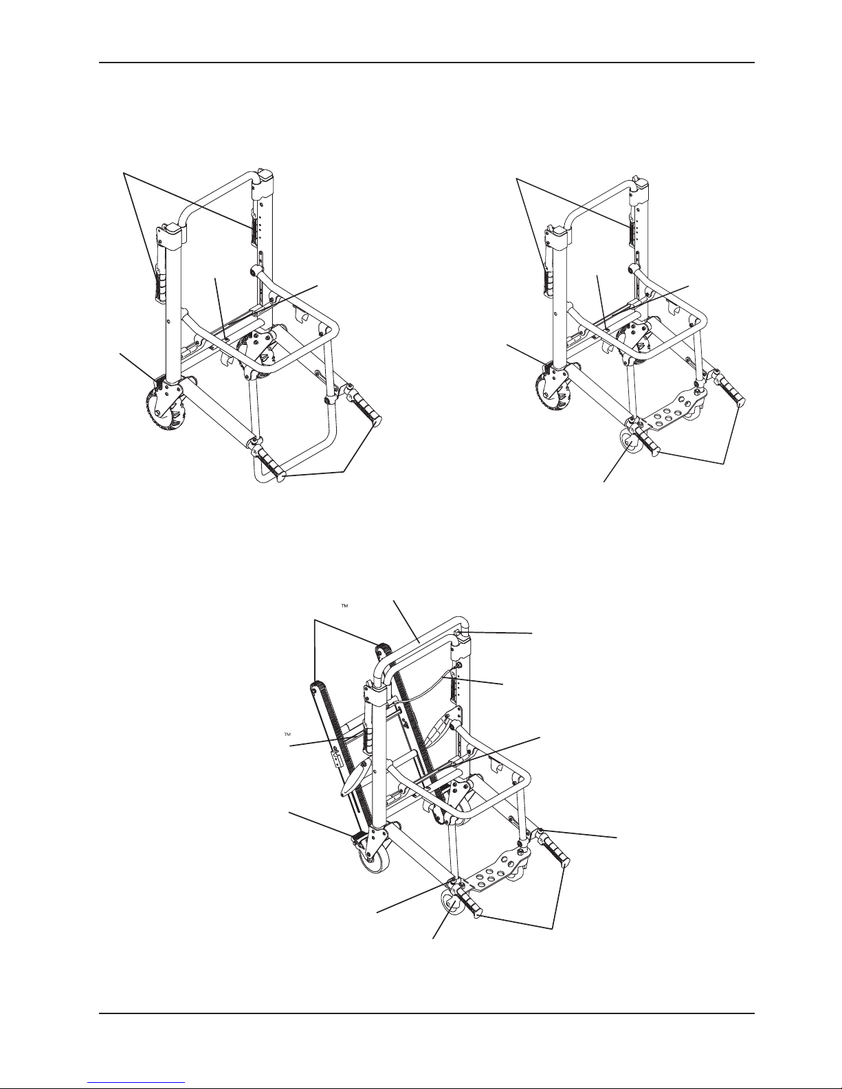
COMPONENT IDENTIFICATION
Introduction
Head End
Lift Handles
Wheel Lock
Serial
Number
Location
6250
Chair Fold
Lock Bar
Foot End
Lift Handles
Lift Handles
Wheel Lock
Head End
Serial
Number
Location
Front Caster
6251
Chair Fold
Lock Bar
Foot End
Lift Handles
Stair−TREAD
Stair−TREAD
Lock Bar
Wheel Lock
Control Handle
Lift Handle
Release Button
Upper
Front Caster
6252
Optional Lift Handles
Release Lever
Upper Control Handle
Release Cable
Chair Fold
Lock Bar
Lift Handle
Release Button
Foot End
Lift Handles
www.stryker.com 6250 -001-160 REV E 7
Return To Table of Contents
Page 8

Warranty
Stryker EMS, a division of the Stryker Corporation, offers two distinct warranty options in the United States:
One (1) year parts and labor. Under this option, Stryker EMS warrants to the original purchaser
that its products should be free from manufacturing non-conformances that affect product
performance and customer satisfaction for a period of one (1) year after date of delivery. Stryker’s
obligation under this warranty is expressly limited to supplying replacement parts and labor for,
or replacing, at its option, any product that is, in the sole discretion of Stryker, found to be defective.
Two (2) year parts. Under this option, Stryker EMS warrants to the original purchaser that nonexpendable components of its products should be free from manufacturing non-conformances
that affect product performance and customer satisfaction for a period of two (2) years after date
of delivery. Stryker’s obligation under this warranty is expressly limited to supplying replacement
parts for, or replacing, at its option, any product which is, in the sole discretion of Stryker, found to
be defective. Expendable components, i.e. mattresses, restraints, I.V. poles, storage nets, storage
pouches, Oxygen straps, and other soft goods, have a one (1) year limited warranty with this option.
Under either warranty option, Stryker EMS products are designed for a 7 year expected service life under
normal use, conditions, and with appropriate periodic maintenance as described in the maintenance
manual for each device. Stryker warrants to the original purchaser that the welds on its EMS products
will be free from structural defects for the expected 7 year life of the EMS product as long as the original
purchaser owns the product. Original purchasers will also obtain a three (3) year limited parts warranty
for the X-frame components of the MX-PRO R3 stretcher provided they also purchase X-frame guards at
the time of the original purchase and the guards are installed on the MX-PRO before it is put into service.
If Stryker requests, products or parts for which an original purchaser makes a warranty
claim, the purchaser shall return the product or part prepaid freight to Stryker’s factory.
Any improper use or alteration or repair by unauthorized service providers in such a manner as
in Stryker’s judgment affects the product materially and adversely, shall void this warranty. Any
repair of Stryker products using parts not provided or authorized by Stryker shall void this warranty.
No employee or representative of Stryker is authorized to change this warranty in any way.
This statement constitutes Stryker EMS’s entire warranty with respect to the aforesaid equipment. STRYKER
MAKES NO OTHER WARRANTY OR REPRESENTATION EITHER EXPRESSED OR IMPLIED, EXCEPT AS SET
FORTH HEREIN. THERE IS NO WARRANTY OF MERCHANTABILITY AND THERE ARE NO WARRANTIES
OF FITNESS FOR ANY PARTICULAR PURPOSE. IN NO EVENT SHALL STRYKER BE LIABLE HEREUNDER
FOR INCIDENTAL OR CONSEQUENTIAL DAMAGES ARISING FROM OR IN ANY MANNER RELATED TO
SALES OR USE OF ANY SUCH EQUIPMENT.
Return To Table of Contents
8 6250- 001-160 REV E www.stryker.com
Page 9

Warranty
STRYKER EMS RETURN POLICY
Cots, Stair Chairs, Evacuation Chairs, Cot Fasteners and Aftermarket Accessories may be returned up to 180 days of
receipt if they meet the following guidelines:
Prior to 30 Days
• 30daymoneybackguaranteeineffect
• StrykerEMSisresponsibleforallcharges
• Returnswillnotbeapprovedonmodifieditems
Prior to 90 Days
• Productmustbeunused, undamaged and in the original packaging
• Customerisresponsiblefora10%restockingfee
Prior to 180 Days
• Productmustbeunused, undamaged and in the original packaging
• Customerisresponsiblefora25%restockingfee
RETURN AUTHORIZATION
Merchandise cannot be returned without approval from the Stryker Customer Service Department. An authorization
number will be provided which must be printed on the returned merchandise. Stryker reserves the right to charge
shipping and restocking fees on returned items.
SPECIAL, MODIFIED, OR DISCONTINUED ITEMS NOT SUBJECT TO RETURN.
DAMAGED MERCHANDISE
ICC Regulations require that claims for damaged merchandise must be made with the carrier within fifteen (15)
days of receipt of merchandise. DO NOT ACCEPT DAMAGED SHIPMENTS UNLESS SUCH DAMAGE IS NOTED
ON THE DELIVERY RECEIPT AT THE TIME OF RECEIPT. Upon prompt notification, Stryker will file a freight claim
with the appropriate carrier for damages incurred. Claim will be limited in amount to the actual replacement cost. In
the event that this information is not received by Stryker within the fifteen (15) day period following the delivery of
the merchandise, or the damage was not noted on the delivery receipt at the time of receipt, the customer will be
responsible for payment of the original invoice in full.
Claims for any short shipment must be made within thirty (30) days of invoice.
INTERNATIONAL WARRANTY CLAUSE
This warranty reflects U.S. domestic policy. Warranty outside the U.S. may vary by country. Please contact your local
Stryker Medical representative for additional information.
PATENT INFORMATION
Stryker products are covered by one or more of the following patents:
United States 5,575,026 6,276,010 6,648,343 6 , 908,13 3 6,796,757
5,537,700 6,125,485 6,735,794 7,10 0, 2 2 4 7,3 9 8 , 5 71
D527,103
Other Patents Pending
www.stryker.com 6250 -001-160 REV E 9
Return To Table of Contents
Page 10

Summary of Safety Precautions
The following is a list of safety precautions that must be observed when operating or servicing this unit. The precautions
are repeated throughout the manual, where applicable. Carefully read this list before using or servicing the unit.
WARNING
• Do not modify the Stair-PRO® Stair Chair. Modifying the chair can cause unpredictable operation resulting in injury
to the patient or operator. Modifying the chair will also void its warranty.
• Do not allow untrained helpers to assist in the operation of the Stair-PRO® Stair Chair. Untrained technicians/
helpers can cause injury to the patient or themselves.
• An unlocked chair can fold during use, causing injury to the patient or operator. Always make sure the chair is
locked in the unfolded position before use.
• To avoid injury, always verify the lift handles are locked in place before using them to lift the chair.
• Always use all restraint straps to secure the patient on the chair. An unrestrained patient may fall from the chair
and be injured.
• Do not push the Model 6252 with the upper control handle in the fully extended position. Pushing the chair with
the handle in the fully extended position may cause the chair to tip when obstacles are encountered.
• Never leave a patient unattended on the chair or injury could result. Hold the chair securely while a patient is on
the chair.
• The Stair-PRO® Stair Chair is not recommended for use with suspected cervical, spinal, or fracture injuries.
• To avoid injury, transporting the patient on stairs requires a minimum of two operators. If more people are required
to safely control the chair, use the chart on page 29 as reference for proper positioning of the helpers.
• Only use the wheel locks during patient transfer or without a patient on the chair. Tipping could occur if the chair
is moved while wheel locks are applied, resulting in injury to the patient or operator and/or damage to the chair.
• Never use a wheel lock on a chair with excessively worn wheels. Using a wheel lock on a wheel with less than a
5” diameter (Model 6252) or a 6” diameter (Models 6250/6251) could compromise the holding ability of the wheel
lock, possibly resulting in injury to the patient or operator and/or damage to the chair or other equipment.
• To avoid injury, always verify the Stair-TREAD™ system on the Model 6252 is securely locked in place before
transporting the patient.
• Water, ice and debris on the stairs can affect operator footing and proper operation of the Stair-TREAD™ system.
To avoid injury, clear the path or consider an alternate route.
• Condensation, water, ice and/or debris on the Stair-TREAD™ system can cause unpredictable performance,
resulting in a sudden change in the weight the operators must support. To avoid injury, and to aid proper operation
of the Stair-TREAD™ system, ensure the belts are clean and dry before transporting the patient.
• Never lubricate the Stair-TREAD™ system. Lubrication on the system can cause inconsistent operation possibly
resulting in injury to the patient or operator.
• To avoid injury to the operators and/or the patient, operators should never attempt to transport patient loads greater
than what they can safely lift.
• Use any appropriate personal safety equipment (goggles, respirator, etc.) to avoid the risk of inhaling contagion. Use
of power washing equipment can aerate contamination collected during the use of the cot.
CAUTION
• Improper usage of the Stair-PRO® Stair Chair can cause injury to the patient or operator. Operate the Stair-PRO
Stair Chair only as described in this manual.
• Improper maintenance can cause injury or damage to the unit. Maintain the Stair-PRO® Stair Chair as described
in this manual. Use only Stryker approved parts and maintenance procedures. Using unapproved parts and
procedures could cause unpredictable operation and/or injury and will void the product warranty.
• Casters are not suitable for all surfaces. Caution should be used at all times.
• Wheel locks are only intended to help prevent the empty chair from rolling while unattended and to aid in patient
transfer. The wheel lock may not provide sufficient resistance on all surfaces or under loads.
• Release the red track release bar before clicking the Stair-TREAD™ system into the locked position. Failure to follow
this procedure could result in the track failing to lock. Always verify the Stair-TREAD™ system is locked by trying
to fold it before descending stairs.
Return To Table of Contents
10 6250 -001-160 REV E www.stryker.com
®
Page 11

Setup Procedures
Unpack the cartons and check all items for proper operation. It is important that the Stair-PRO® Stair Chair is working
properly before it is put into service. Have a qualified service person use the following list and the operation instructions
to check the chair before it is put into service.
• All fasteners secure (reference all assembly drawings).
• All welds intact, not cracked or broken.
• No bent or broken tubing or sheet metal.
• No debris in wheels.
• All wheels secure and rolling properly.
• Chair unfolds and locks properly.
• No rips or cracks in seat or backrest.
• Patient restraints intact and working properly.
• Wheel locks operating properly.
• Foot end lift handles extend and lock properly.
• Head end lift handles fold and unfold.
• Front casters secure, rolling and swiveling properly (if equipped).
• Upper control handle extends and locks in all positions (if equipped).
• Stair-TREAD™ system unfolds and locks (if equipped).
• Track belts roll properly (if equipped).
• Optional accessories intact and operating properly.
The storage compartment on the vehicle in which the Stair-PRO® Stair Chair will be transported must be large enough
to accommodate the folded dimensions of the chair (see page 6).
When necessary, modify the vehicle to fit the chair. Do not modify the chair.
WARNING
Do not modify the Stair-PRO® Stair Chair. Modifying the chair can cause unpredictable operation resulting in injury to the
patient or operator. Modifying the chair will also void its warranty.
www.stryker.com 6250 -001-160 REV E 11
Return To Table of Contents
Page 12

Operation Guide
OPERATING GUIDELINES
• Use the Stair-PRO® Stair Chair only as described in this manual.
• Read all labels and instructions on the chair before using the chair.
• When a patient is on the chair, use a minimum of two operators to manipulate the chair on stairs. If more people
are required to safely control the chair, use the chart on page 29 as reference for proper positioning of the
helpers.
• Do not roll the chair, ascend, or descend stairs without advising the patient. Stay with the patient and control the
chair at all times.
• Only use the wheel locks during patient transfer or without a patient on the chair.
• Always use the restraint straps when a patient is on the chair.
• Use properly trained helpers when necessary to control the chair and patient.
WARNING
• Always use all restraint straps to secure the patient on the chair. An unrestrained patient may fall from the chair
and be injured.
• Only use the wheel locks during patient transfer or without a patient on the chair. Tipping could occur if the chair
is moved while the wheel locks are applied, resulting in injury to the patient or operator and/or damage to the chair.
• Condensation, water, ice and/or debris on the Model 6252 Stair-TREAD™ system can cause unpredictable
performance, resulting in a sudden change in the weight the operators must support. To avoid injury, and to aid
proper operation of the Stair-TREAD™ system, ensure the belts are clean and dry before transporting the patient.
• To avoid injury to the operators and/or the patient, operators should never attempt to transport patient loads greater
than what they can safely lift.
Return To Table of Contents
12 6250- 001-160 REV E www.stryker.com
Page 13
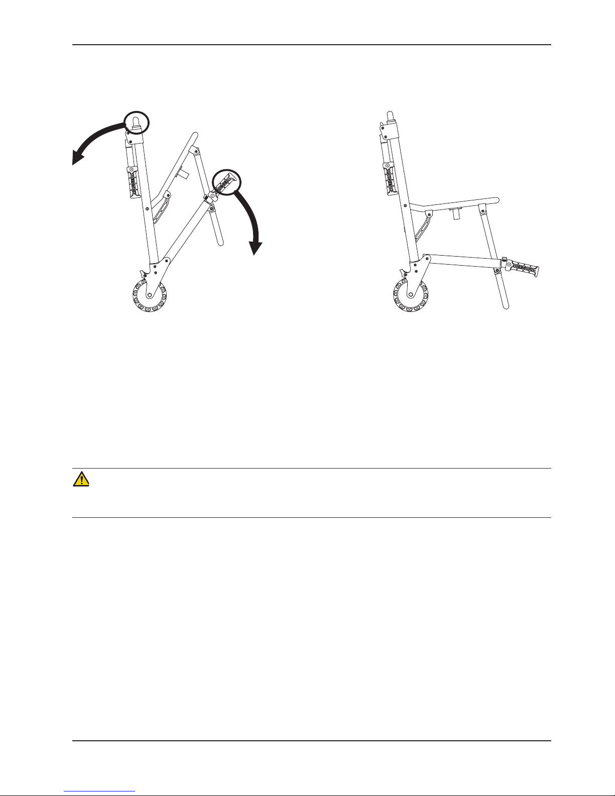
UNFOLDING THE CHAIR
Operation Guide
Figure 1a - Unfolding the Chair
(6250 Shown)
To unfold the chair (refer to Figure 1a above):
1. Stand behind the chair.
2. Apply the wheel locks (if desired).
3. Pull the backrest and the extension handle apart. The lock mechanism will automatically engage when the chair
is completely unfolded.
4. Verify the lock is engaged by pulling up on the seat. If the lock is properly engaged, the chair will not fold.
WARNING
An unlocked chair can fold during use, causing injury to the patient or operator. Always make sure the chair is locked
in the unfolded position before use.
www.stryker.com 6250 -001-160 REV E 13
Return To Table of Contents
Page 14
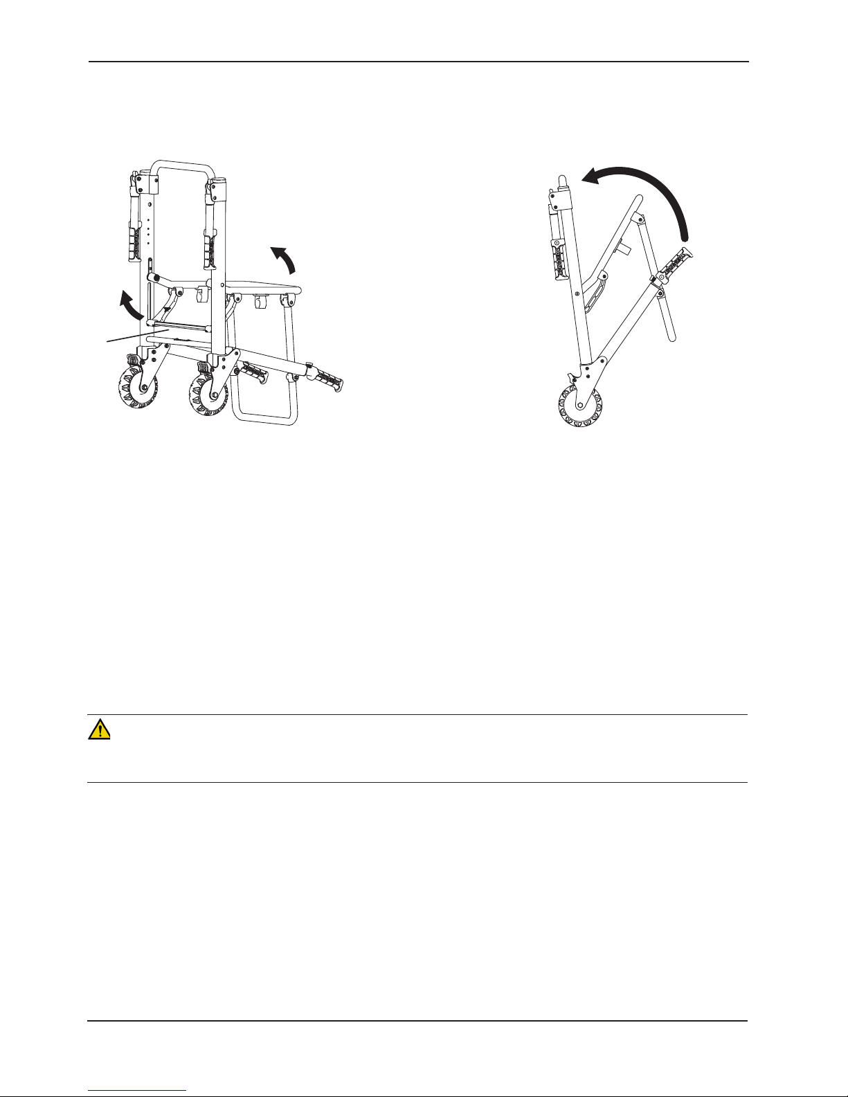
FOLDING THE CHAIR
Operation Guide
Figure 1b - Folding the Chair
(6250 Shown)
To fold the chair (refer to Figure 1b above):
1. Apply the wheel locks (if desired). Buckle the restraint straps and fold them neatly to prevent them from interfering
with proper folding of the chair. If the chair is equipped with the optional head support strap, secure it behind the
chair frame.
2. Stand at the side of the chair.
3. Pull up on the red lock bar at the rear of the chair.
4. Tip the chair forward.
5. Fold the seat up to the backrest until the front legs lock in the clips on the bottom of the seat tube.
Note: On models 6251 and 6252, rotate the front casters so they do not interfere with folding the chair.
WARNING
An unlocked chair can fold during use, causing injury to the patient or operator. Always make sure the chair is locked
in the unfolded position before use.
Return To Table of Contents
14 6250- 001-160 REV E www.stryker.com
Page 15

Operation Guide
TRANSFERRING THE PATIENT TO THE STAIR-PRO® STAIR CHAIR
To transfer the patient to the chair:
1. Place the chair beside the patient.
2. Apply the wheel locks to prevent the chair from moving.
3. Open the restraint straps.
4. Transfer the patient to the chair using accepted EMS procedures.
5. Use all the restraints to secure the patient on the chair (page 16).
6. Disengage the wheel locks before transporting.
WARNING
The Stair-PRO® is not recommended for use with suspected cervical, spinal, or fracture injuries.
www.stryker.com 6250 -001-160 REV E 15
Return To Table of Contents
Page 16
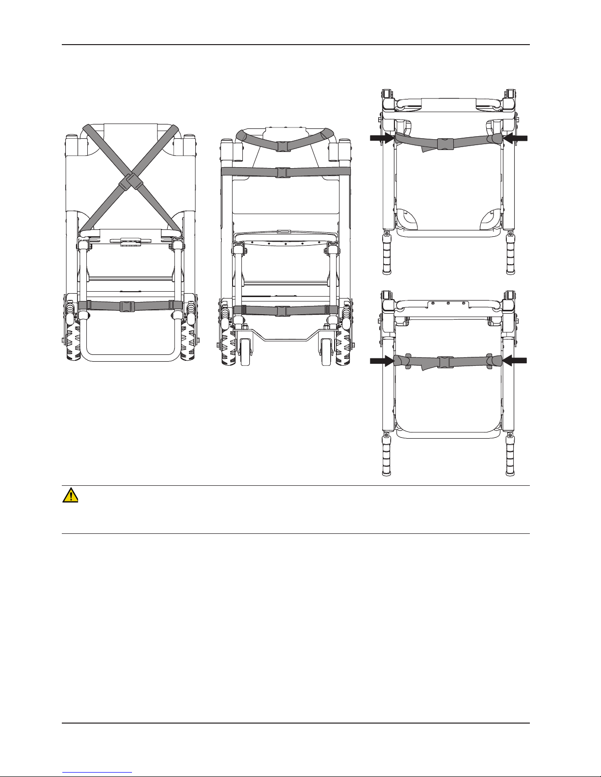
USING RESTRAINT STRAPS
Operation Guide
Vinyl Seat
Top Vi e w
Figure 2
Cross-Chest Configuration
Figure 3
Chest and Lap Strap
Configuration
ABS Seat
Top Vi e w
Figure 4
Lap Strap
Attachment Points
WARNING
Always use all restraint straps to secure the patient on the chair. An unrestrained patient may fall from the chair and be
injured.
The restraints can be used in two configurations.
For the cross-chest configuration (Figure 2): Buckle the chest restraints in an “X” pattern across the patient’s chest.
For the chest and lap configuration (Figure 3): Buckle one restraint across the patient’s chest and the other across
the patient’s lap.
For either configuration: Match up the color coded restraints and buckle the ankle restraint across the patient’s legs.
To avoid damage to the buckles and straps, keep the restraint straps buckled when the chair is not being used with a
patient.
When attaching the restraint straps to the chair, remember the attachment points must provide strong anchorage and
proper restraint position while not interfering with equipment and accessories.
Return To Table of Contents
16 6250 -001-160 REV E www.stryker.com
Page 17
Operation Guide
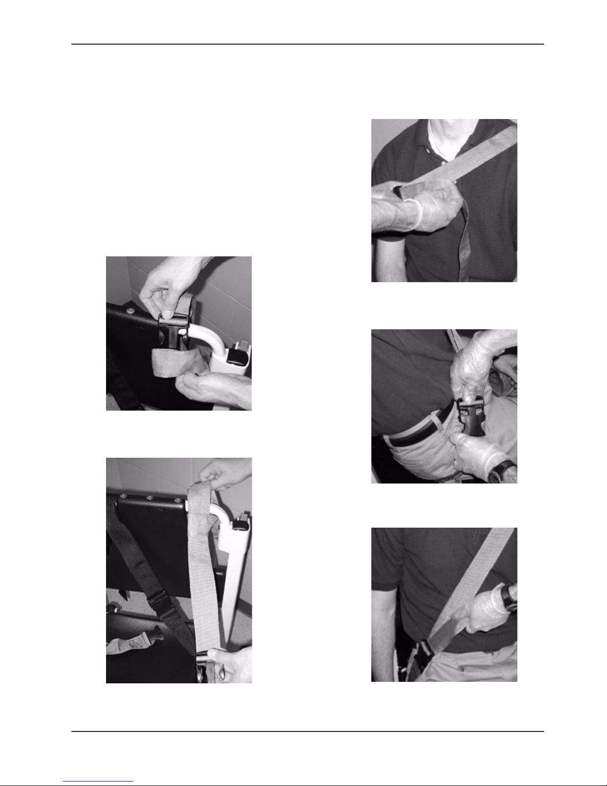
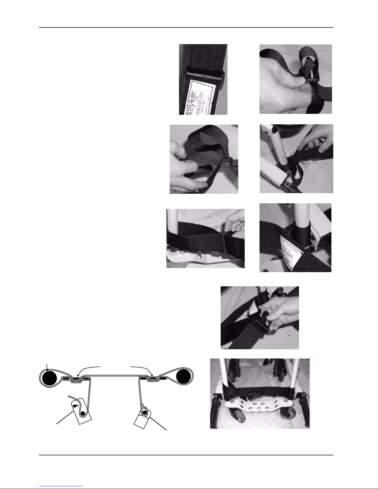
USING RESTRAINT STRAPS - CONTINUED
To attach the chest straps in the cross-chest configuration:
1. Wrap each strap around the chair frame, insert the end through
the loop on the end of the strap and pull it tight.
2. Pull the strap across the patient’s chest, lengthening the strap
as necessary.
3. Buckle the strap.
4. Pull the loose end of the strap to tighten it securely around
the patient.
5. Repeat for the second strap and the lap belt.
Figure 7 - Lengthen strap as
necessary
Figure 5 - Insert the end through
the loop
Figure 6 - Pull the strap tight
Figure 8 - Buckle strap
Figure 9 - Tighten strap securely
www.stryker.com 6250 -001-160 REV E 17
Return To Table of Contents
Page 18
Operation Guide
USING RESTRAINT STRAPS - CONTINUED
To attach the ankle strap:
1. Remove the three plastic pieces from the
strap.
2. Thread the strap through one of the
plastic “D” rings and slide the ring down to
the end of the strap up to the white label.
3. Loop the strap around the front leg of
the chair and pull the loose end of the
strap through the ring. Pull until the
ring rests against the foot rest tube.
4. Thread the strap through the other “D”
ring.
5. Loop the strap around the other front leg
of the chair and pull the loose end of
the strap through the loop. Pull until the
“D” ring rests against the foot rest tube.
6. Attach the final “male” end clip on the
strap.
Return To Table of Contents
18 6250 -001-160 REV E www.stryker.com
Figure 10-18 - Attaching the leg strap
Page 19

Operation Guide
USING RESTRAINT STRAPS - CONTINUED
• To lengthen the restraint, grasp the buckle, turn it at an angle to the webbing and pull it out. A hemmed tab at the
end of the webbing prevents the buckle from coming off the strap. To shorten the restraint, grasp the hemmed tab
and pull the webbing back through the buckle until the required tightness is achieved.
• When the chair is put into service, open the restraints and place them at either side of the chair until the patient
is positioned on the seat. Lengthen the restraint, buckle it around the patient and shorten it until the required
tightness to properly secure the patient is achieved.
• To open the restraint, press the tabs on the side of the buckle to release the buckle and pull the tang out of the
receiver. To close the restraint, push the tang into the receiver until a ”click” is heard.
• Whenever a restraint is buckled on a patient, the attendant should verify the tang is locked and the extra webbing
is not tangled in the chair or hanging loose.
• Inspection of the restraints should be done at least once a month (more frequently if used heavily). Inspection
should include checking for a bent or broken receiver or tang, torn or frayed webbing, etc. Any restraint showing
wear or not operating properly must be replaced immediately.
PROPER LIFTING TECHNIQUES
When lifting the Stair-PRO® Stair Chair and patient, remember these five basic guidelines:
• Keep your hands close to your body.
• Keep your back straight.
• Coordinate your movements with your partner and lift with your legs.
• Avoid twisting.
• Always operate the Stair-PRO® Stair Chair as described in this manual.
www.stryker.com 6250 -001-160 REV E 19
Return To Table of Contents
Page 20
Operation Guide
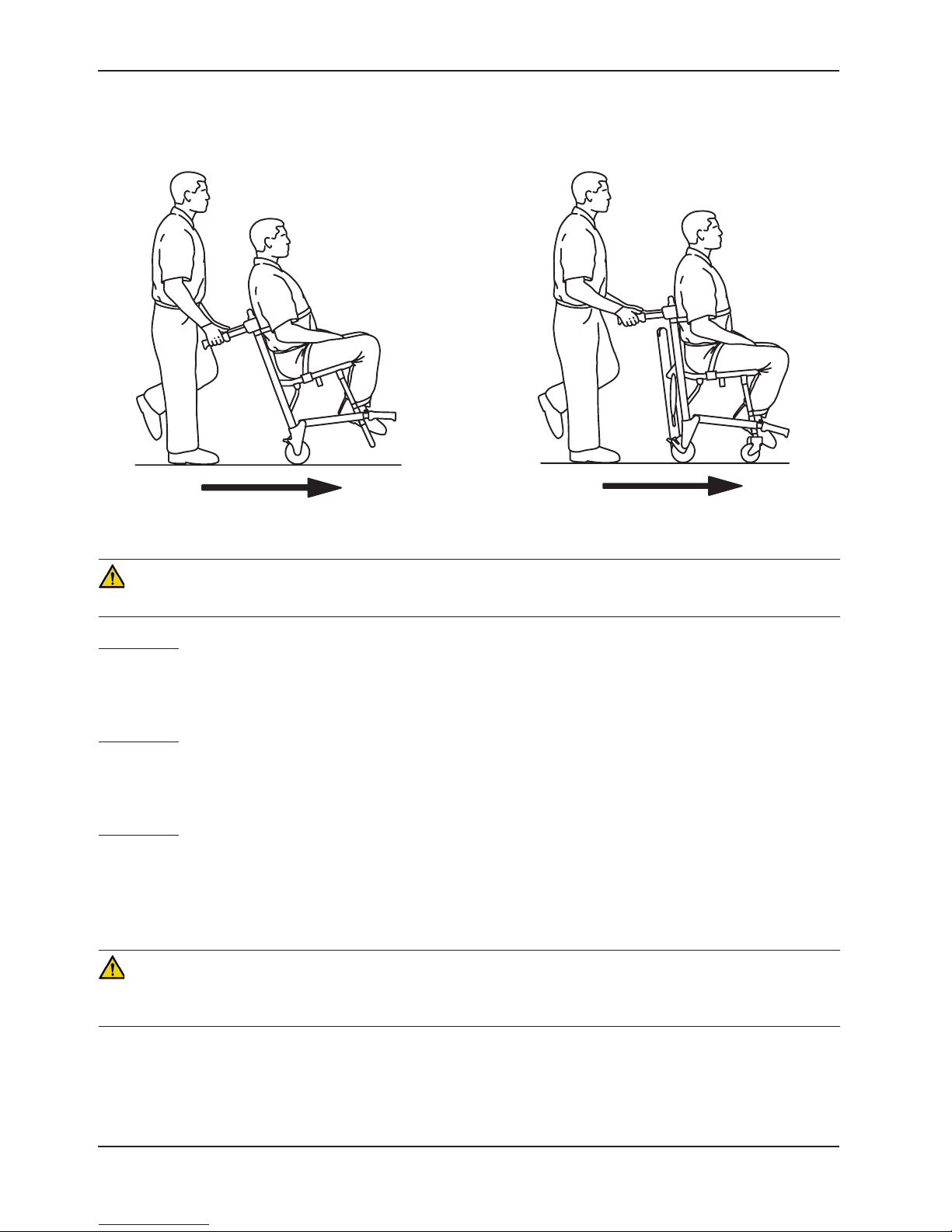
TRANSPORTING THE PATIENT ON FLAT SURFACES
Figure 19 - Transporting the Patient on a Model 6250
Figure 20 - Transporting the Patient on a Model 6252
CAUTION
Casters are not suitable for all surfaces. Caution should be used at all times.
Model 6250
To roll the Model 6250 Stair-PRO® over flat surfaces, use either the locking rear lift handles (if equipped), or the
backrest tube to tip the chair back. Once the chair is tipped back, use either the head end lift handles or the backrest
tube to roll and guide the chair. Lift the chair over and around obstructions with the head end and foot end lift handles.
Model 6251
To roll the Model 6251 Stair-PRO® over flat surfaces, push and guide the chair from the rear of the patient, using either
the head end lift handles or the backrest tube. Lift the chair over and around obstructions with the head end and foot
end lift handles.
Model 6252
To roll the Model 6252 Stair-PRO® over flat surfaces, follow the same method as above for the Model 6251. In addition
to the head end lift handles, the extendable upper control handle can be used in any position to roll and guide the chair.
Extend the upper control handle by pulling the red release cable with one hand, and pulling up on the control handle
with the other. Release the cable to lock the handle in either the intermediate or fully extended position. Lift the chair
over and around obstructions with the head end and foot end lift handles.
WARNING
Do not push the Model 6252 with the upper control handle in the fully extended position. Pushing the chair with the
handle in the fully extended position may cause the chair to tip when obstacles are encountered.
Return To Table of Contents
20 6250 -001-160 REV E www.stryker.com
Page 21
Operation Guide
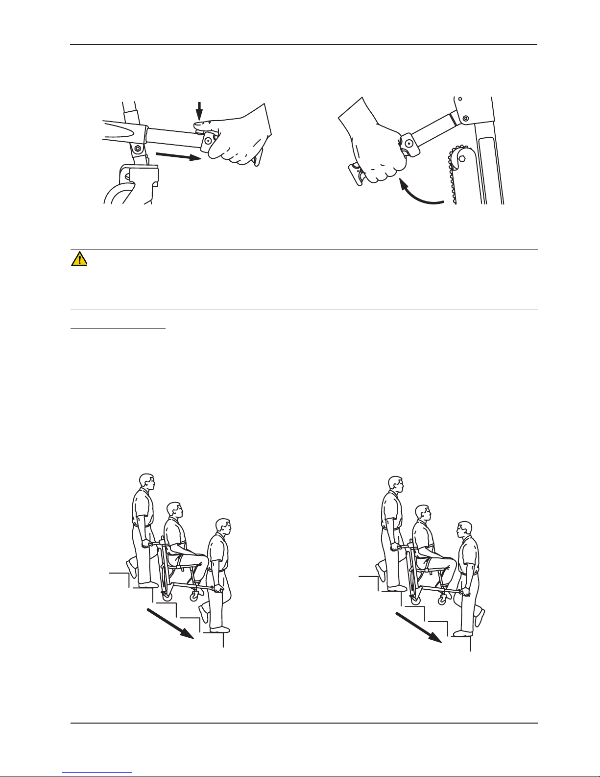
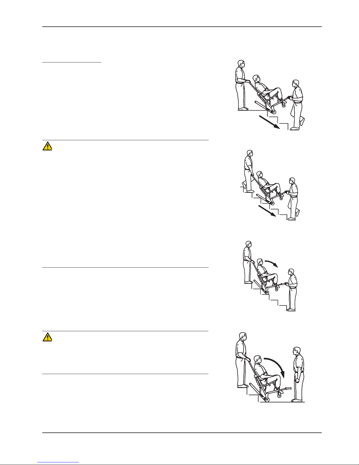
TRANSPORTING THE PATIENT DOWN STAIRS
Figure 21 - Foot end lift handles
Figure 22 - Head end lift handles
WARNING
To avoid injury, transporting the patient on stairs requires a minimum of two operators. If more people are required to
safely control the chair, use the chart on page 29 as reference for proper positioning of the helpers. To avoid injury,
always verify the lift handles are locked in place before using them to lift the chair.
Models 6250 and 6251
1. Foot end operator - descend in front of the Stair-PRO® Stair Chair.
2. Head end operator - approach the stairs squarely.
3. Foot end operator - push each red foot end lift handle button and pull out each handle until it stops. Release the
button and verify the handle is locked securely in position.
4. Head end operator - unfold the head end lift handles and face down the stairs.
5. Foot end operator - either face backward for improved patient monitoring or forward for an improved view of the
stairs and easier maneuvering around obstacles.
Note: Although the front operator can face either direction while lifting and carrying,
any applicable protocols for carrying chairs should be followed.
6. Both operators - simultaneously lift the chair, using the head and foot end lift handles and following the
proper lifting techniques (see page 19). Carry the chair slowly down the stairs, avoiding any obstructions.
www.stryker.com 6250 -001-160 REV E 21
Figure 23 and 24 - Transporting down stairs
Return To Table of Contents
Page 22
Operation Guide
TRANSPORTING THE PATIENT DOWN STAIRS - CONTINUED
Model 6252
WARNING
• To avoid injury, always verify the Stair-TREAD™ system on the
Model 6252 is locked in place before transporting the patient.
• To avoid injury, transporting the patient on stairs requires a
minimum of two operators. If more people are required to safely
control the chair, use the chart on page 29 as reference for
proper positioning of the helpers.
• To avoid injury, always verify the lift handles are locked in place
before using them to lift the chair.
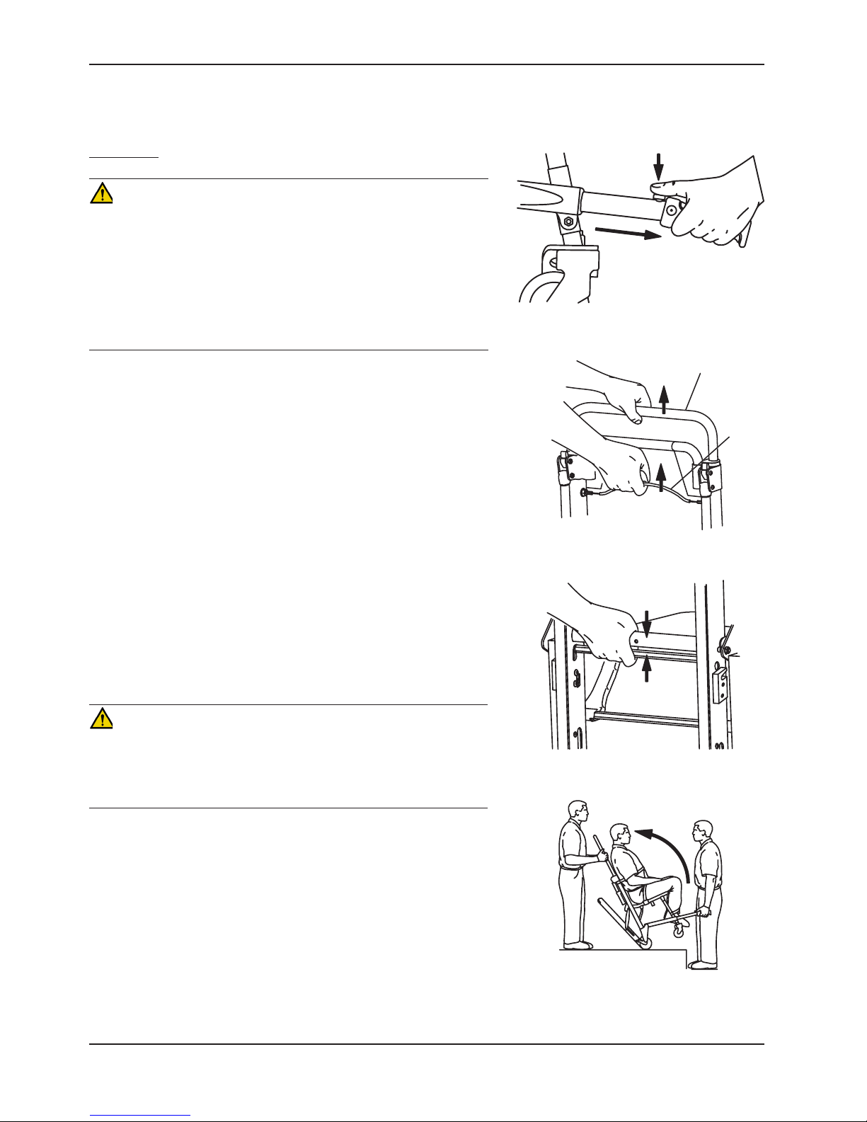
1. Roll the chair to the stairs and align it squarely with the edge of
the first step.
2. Foot end operator - Extend the foot end lift handles by pushing
the red release buttons and pulling the handles out until they stop.
Release the buttons and verify the handles are locked.
3. Head end operator - Use one hand to pull the red upper control
handle release cable while using the other hand to pull up and
fully extend the handle. Release the cable and verify the handle
is locked on both sides in the fully extended position.
4. Head end operator - Squeeze the red track release bar against
the black cross tube. Relax your grip on the release bar and
forcefully pull the Stair-TREAD™ system to the fully extended
position until both sides lock securely. Always verify both sides of
the Stair-TREAD™ system are locked by trying to fold it back up.
CAUTION
Release the red track release bar before clicking the Stair-TREAD™
system into the locked position. Failure to follow this procedure could
result in the track failing to lock. Always verify the Stair-TREAD™
system is locked by trying to fold it before descending stairs.
Figure 25 - Foot end lift handles
Figure 26 - Upper control handle release cable
Figure 27 - Red track release bar
5. Operators face each other while descending the stairs.
6. Head end operator - Tilt the chair back just far enough to allow
the Stair-TREAD™ system to contact the floor.
Return To Table of Contents
22 6250 -001-160 REV E www.stryker.com
Figure 28 - Tilt the chair
Page 23
Operation Guide
TRANSPORTING THE PATIENT DOWN STAIRS - CONTINUED
Model 6252 - Continued
7. Both operators - Maintaining the angle, guide the Stair-PRO® Stair
Chair over the edge of the stairs, allowing the Stair-TREAD™
system to engage the first step.
8. Both operators - Glide down the stairs until the treads are level
across the edges of two or three steps.
9. Head end operator - Apply slight downward pressure on the
extendable upper control handle while the foot end operator
applies slight upward pressure on the foot end lift handles to
keep the chair from rocking forward as it glides down the stairs.
WARNING
• The Stair-TREAD™ system may not work the same on all
stair surfaces and in all environmental conditions. Based on
conditions, varying amounts of resistance may be encountered.
Avoid getting dirt or other obstructions inside the tracks. Water, ice
and/or debris on the stairs can affect operator footing and proper
operation of the Stair-TREAD™ system. To avoid injury, clear the
path or consider an alternate route. Condensation, water, ice and/
or debris on the Stair-TREAD™ system can cause unpredictable
performance, resulting in a sudden change in the weight the
operators must support.
• To avoid injury, and to aid proper operation of the Stair-TREAD™
system, ensure the belts are clean and dry before transporting
the patient.
• To avoid injury to the operators and/or the patient, operators should
never attempt to transport patient loads greater than what they can
safely lift.
Figure 29 - Track engaging first step
Figure 30 - Transporting down the stairs
10. Foot end operator - when the track reaches the last step, release
the front handles. Head end operator - allow the chair to tip
forward until all four wheels are on the ground. Roll the chair as
described on page 20.
11. To fold the Stair-TREAD™ system, pull the red track release bar
toward the black cross bar and fold the track up toward the chair.
Verify the Stair-TREAD™ system is locked in place.
Figure 31 - “Resting position”
CAUTION
Release the red track release bar before clicking the Stair-TREAD™
system into the locked position. Failure to follow this procedure could
result in the track failing to lock. Always verify the Stair-TREAD™
system is locked by trying to fold it before descending stairs.
If, while descending the stairs, either operator needs to pause or rest,
tilt the chair forward just enough to allow the rear wheels to rest in
the crook of the stair. To continue down the stairs from the resting
position, the head end operator exerts slight downward pressure on
the upper control handle while the foot end operator provides slight
upward pressure to tilt the chair back and engage the Stair-TREAD™
system.
www.stryker.com 6250 -001-160 REV E 23
Figure 32 - Bottom of stairs
Return To Table of Contents
Page 24
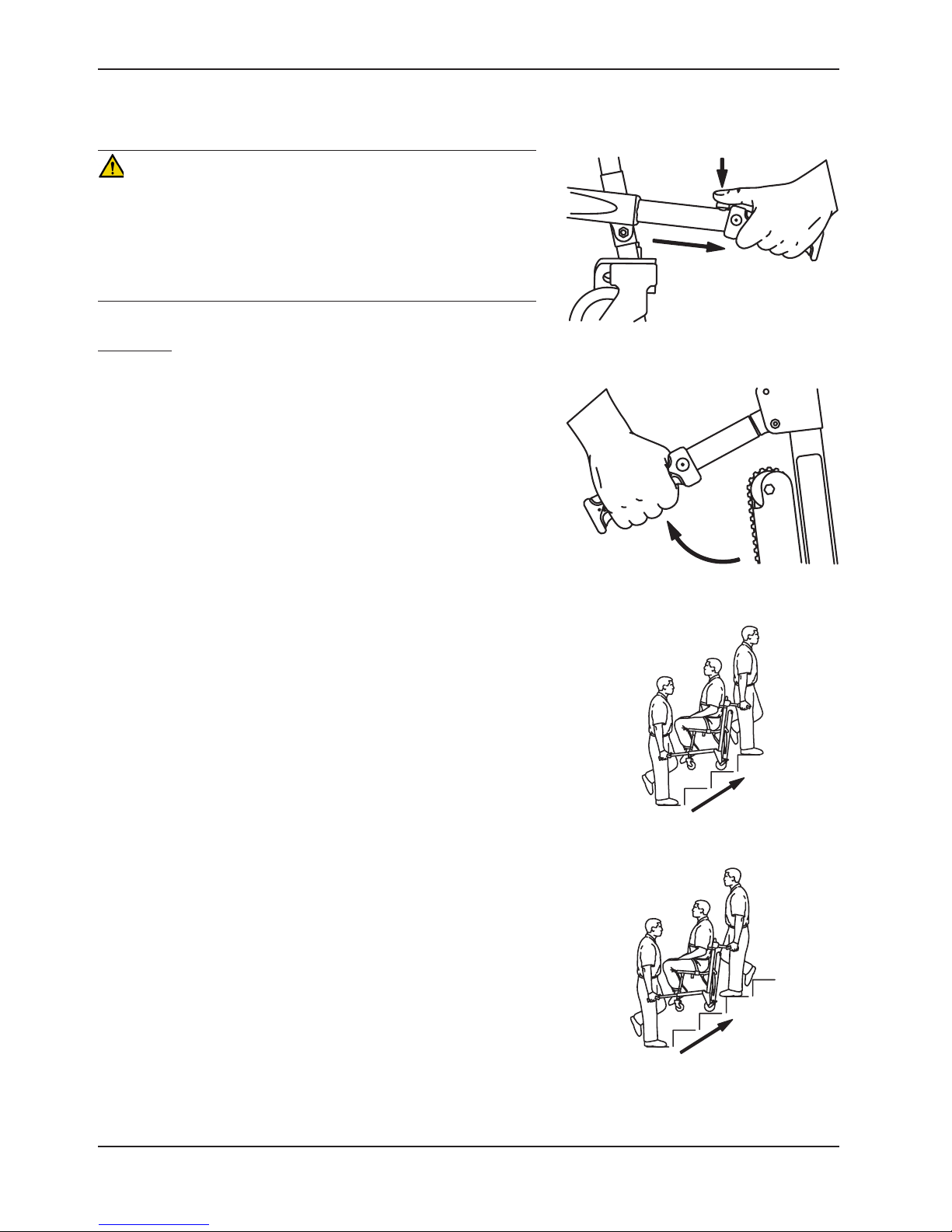
Operation Guide
TRANSPORTING THE PATIENT UP STAIRS
WARNING
• To avoid injury, transporting the patient on stairs requires a
minimum of two operators. If more people are required to safely
control the chair, use the chart on page 29 as reference for
proper positioning of the helpers.
• To avoid injury, always verify the lift handles are locked in place
before using them to lift the chair.
All Models
1. Roll the chair to the bottom of the stairs with the patient’s back
to the stairs.
2. Foot end operator - extend the foot end lift handles by pushing the
red buttons and pulling the handles until they stop. Release the
button and verify the handle is locked.
3. Head end operator - unfold the head end lift handles.
4. The foot end operator faces up the stairs. The head end operator
may either face backward for improved patient monitoring or
forward for an improved view of the stairs and easier maneuvering
around obstacles.
Note: Although the head end operator can face either direction
while carrying, any applicable protocols for carrying chairs should
be followed.
5. Both operators - simultaneously lift the chair, using the head and
foot end lift handles and following proper lifting techniques (see
page 19). Carry the chair slowly up the stairs, avoiding any
obstructions.
Figure 33 - Foot end lift handles
Figure 34 - Head end lift handles
Return To Table of Contents
24 6250 -0 01-160 REV E www.stryker.com
Figure 35 - Transporting up the stairs
Figure 36 - Transporting up the stairs
Page 25
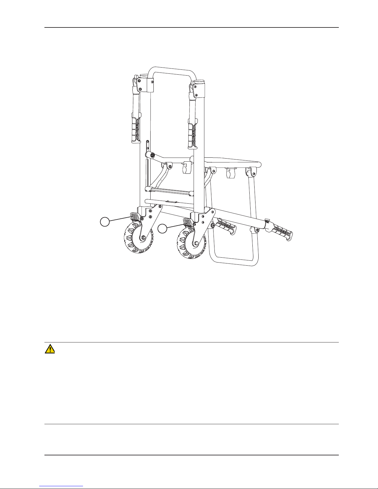
OPERATING THE WHEEL LOCKS
Operation Guide
A
A
Figure 37 - Wheel Locks
(6250 Shown)
To activate the wheel locks:
1. Press down on the pedals (A) until they stop.
2. To release the wheel locks, depress the upper face of the pedal with your foot or lift up with your toe under the
pedal. The upper portion of the pedal will rest against the chair frame when the wheel lock is released.
WARNING
• Only use wheel locks during patient transfer or without a patient on the chair. Tipping could occur if the chair is
moved while the wheel locks are applied, resulting in injury to the patient or operator and/or damage to the chair.
• Wheel locks are only intended to help prevent the empty chair from rolling while unattended, and to aid in patient
transfer. A wheel lock may not provide sufficient resistance on all surfaces or under loads.
• Never leave a patient unattended on the chair or injury could result. Hold the chair securely while a patient is on
the chair.
• Never use a wheel lock on a chair with excessively worn wheels. Using a wheel lock on a wheel with less than a
5” diameter (Model 6252) or a 6” diameter (Models 6250/6251) could compromise the holding ability of the wheel
lock, possibly resulting in injury to the patient or operator and/or damage to the chair or other equipment.
www.stryker.com 6250 -001-160 REV E 25
Return To Table of Contents
Page 26

Operation Guide
ADJUSTING THE WHEEL LOCKING FORCE
Minimum MaximumFigure 38 - Wheel locking force adjustment
To adjust the wheel locking force:
1. Remove the screw from the center of the lock pedal.
2. Remove the octagonal sleeve (B) from the pedal (A).
3. Rotate the octagonal sleeve counterclockwise to increase the pedal locking force or clockwise to decrease the
locking force.
4. Insert the octagonal sleeve (B) into the pedal (A).
5. Reinstall the screw into the center of the lock pedal.
6. Test the pedal locking force and verify that it holds properly before returning the chair to service.
Note: If, after adjustment, the pedal still does not hold the wheel properly, replace the wheel.
Return To Table of Contents
26 6250 -001-160 REV E www.stryker.com
Page 27

Operation Guide
OPERATING THE OPTIONAL LOCKING REAR LIFT HANDLES
WARNING
To avoid injury, always verify the lift handles are locked in place before using them to tip the chair back.
Figure 39 - Rotate the handle up Figure 40 - Pull the trigger
To use the locking rear lift handles: Rotate the handles up until they lock into place. Verify the handles are locked
securely into place before tipping the chair back.
To lower the handles: Lift up on the handle, pull the red trigger toward you with your thumb and fold the handle down
against the chair frame.
www.stryker.com 6250 -001-160 REV E 27
Return To Table of Contents
Page 28

Operation Guide
USING THE OPTIONAL HEAD SUPPORT (MODEL 6252 ONLY)
TOP VIEW
Upper Control Handle
Figures 41-43 - Attaching and using the head support
Slide Ring
Head Support
WARNING
The Stair-PRO® Stair Chair is not recommended for use with suspected cervical, spinal, or fracture injuries.
Before using the optional head support, the upper control handle must be extended. First, pull the red upper control
handle release cable with one hand. Then, pull up on the handle with the other hand. Release the cable and verify the
handle is securely locked into one of the two available positions.
To attach the optional head support to the extendable upper control handle:
1. Wrap the loose ends of the strap around the vertical portions of the handle, then feed them through the plastic
loops.
2. Pull tight, and secure the strap to itself.
3. Adjust the height by loosening the strap, moving it to the desired location, and tightening it again.
To support the patient’s head, position at the base of the head. For unconscious, or semiconscious patients, secure
the head using the other two parts of the strap. Wrap around the patient’s head, and overlap the straps to the desired
tightness to secure. When not in use, these straps can be wrapped back around the handle and attached to the back
of the support.
Return To Table of Contents
28 6250-001-160 REV E w ww.stryker.com
Page 29

Operation Guide
USING ADDITIONAL ASSISTANCE
WARNING
To avoid injury, transporting the patient on stairs requires a minimum of two operators. If more people are required to
safely control the chair, use the chart below as reference for proper positioning of the helpers.
DOWN STAIRS UP STAIRS
Two Operators
Two Operators
One Helper
Two Operators
Two H elp e rs
Operator Operator
Operator
Operator Operator
rotarepOrepleH
Helper Operator
rotarepOrepleHrepleHrotarepOrotarepO Operator
rotarepOrepleH
Helper
Two Operators
Three Helpers
Operator
www.stryker.com 6250 -001-160 REV E 29
Helper
rotarepOrepleH
Helper
Helper
Operator
rotarepOrepleH
Helper
Return To Table of Contents
Page 30

Cleaning
The Model 6250, 6251 and 6252 Stair Chairs are designed to be power-washable. The unit may show some signs of
oxidation or discoloration from continuous washing, however, no degradation of the chair’s performance characteristics
or functionality will occur due to power washing as long as the proper procedures are followed.
WASHING PROCEDURE
• Follow the cleaning solution manufacturer’s dilution recommendations exactly.
• The preferred method Stryker Medical recommends for power washing stair chairs is with the standard hospital
surgical cart washer or hand held wand unit.
WASHING LIMITATIONS
WARNING
Use any appropriate personal safety equipment (goggles, respirator, etc.) to avoid the risk of inhaling contagion. Use
of power washing equipment can aerate contamination collected during the use of the cot.
• DO NOT STEAM CLEAN OR ULTRASONICALLY CLEAN THE UNIT.
• Maximum water temperature should not exceed 1800F/820C. Maximum air dry temperature (cart washers) is
2400F/1150C.
• Maximum water pressure should not exceed 1500 psi/130.5 bar. If a hand held wand is being used to wash the unit,
the pressure nozzle must be kept a minimum of 24 inches/61 centimeters from the unit. Failure to comply with these
instructions may invalidate any and or all warranties.
If a foreign material gets between the Stair-TREAD™ system belt and track frame on the Model 6252, the track frame
must be cleaned.
1. Loosen the track belts and remove the rear wheels (see page 37 for instructions).
2. Clean the track frame completely with rubbing alcohol.
3. Use water at high pressure (see above) to rinse the belts. Be sure to clean both the inside and outside belt
surfaces.
4. Allow the belts to completely dry before reassembly.
5. Reassemble the track belts and the rear wheels (see page 37 for instructions).
6. Following the appropriate cautions and warnings, test the performance of the chair using a simulated patient
weight while descending a flight of stairs.
7. If performance does not return to the original condition, the belts may need to be reconditioned or replaced.
Return To Table of Contents
30 6250 -0 01-160 REV E www.stryker.com
Page 31

Cleaning
In general, when used in those concentrations recommended by the manufacturer, either phenolic type or quaternary
(excluding Virex® TB) type disinfectants can be used. Iodophor type disinfectants are not recommended for use
because staining may result.
Suggested cleaners for the 6250, 6251, and 6252 surfaces:
• Quaternary Cleaners (active ingredient - ammonium chloride)
• Phenolic Cleaners (active ingredient - o-phenylphenol)
• ChlorinatedBleachSolution(5.25%-lessthan1partbleachto100partswater)
Avoid over saturation and ensure the product does not stay wet longer than the chemical manufacturer’s guidelines
for proper disinfecting.
WARNING
• SOME CLEANING PRODUCTS ARE CORROSIVE IN NATURE AND MAY CAUSE DAMAGE TO THE PRODUCT IF
USED IMPROPERLY. If the products described above are used to clean Stryker patient care equipment, measures
must be taken to insure the chairs are wiped with a cloth soaked in clean water and thoroughly dried following
cleaning.
• Failure to properly rinse and dry the chairs will leave a corrosive residue on the surface of the chairs, possibly
causing premature corrosion of critical components.
Note: Failure to follow the above directions when using these types of cleaners may void this product’s warranty.
www.stryker.com 6250 -001-160 REV E 31
Return To Table of Contents
Page 32

Preventative Maintenance
Operation Schedule Procedure
Cleaning and Disinfecting Each Use See page 30
For 1-25 calls per month, inspect chair every 6 months
Inspection
Stair-TREAD™ system belt
reconditioning (6252)
Note: Keep up to date maintenance records using the Maintenance Record form on page 33.
Parts, Service or Technical Assistance
Contact Stryker Customer Service at 1-800-327-0770 or
Stryker Medical
3800 E. Centre Ave. Portage, MI 49002
ATTN: Customer Service
For 26-200 calls per month, inspect chair every 3 months
For 201+ calls per month, inspect chair monthly
After usage on approximately 500 flights of stairs or if the
Stair-TREAD™ system performance is sluggish
CHECKLIST
See below for
checklist
See page 40
____ _ All fasteners secure (reference all assembly drawings)
__ ___ All welds intact, not cracked or broken
__ ___ No bent or broken tubing or sheet metal
__ ___ No debris in wheels
__ ___ All wheels secure and rolling properly
__ ___ Front casters secure, rolling and swiveling properly (if equipped)
__ ___ Wheel locks hold wheels securely when on and clear the wheels when off
__ ___ Chair unfolds and locks properly
__ ___ No rips or cracks in seat or back rest
__ ___ Restraint straps intact and working properly
____ _ Foot end carrying handles extend and lock properly
__ ___ Head end carrying handles fold and unfold
__ ___ Upper control handle extends and locks in all positions (if equipped)
____ _ Stair-TREAD™ system mechanism unfolds and locks properly (if equipped)
__ ___ Stair-TREAD™ system belt rolls properly (if equipped)
__ ___ Stair-TREAD™ system belt inner cords not showing - replace if necessary (if equipped)
__ ___ Stair-TREAD™ system performs as desired - recondition belts if necessary (if equipped) (see page 40)
__ ___ No lubricants present on the Stair-TREAD™ system belts or the track frame surfaces
__ ___ Upper release handle cable not worn or frayed - replace, if necessary (Model 6252)
____ _ Optional accessories intact and operating properly
Serial Number:
Completed by: _______________________________________ Date: _________________
Return To Table of Contents
32 6250 -001-160 REV E www.stryker.com
Page 33

Maintenance Record
Date Maintenance Operation Performed By Hours
www.stryker.com 6250 -001-160 REV E 33
Return To Table of Contents
Page 34

Training Record
Training Date Training Method
Trainee Name Basic
Training
Refresher
Update
Owner’s Manual, In-Service,
Formal Class, Etc.
Return To Table of Contents
34 6250 -001-160 REV E www.stryker.com
Page 35

Quick Replacement Part List
The parts and accessories listed on this page are all currently available for purchase. Some of the parts identified on
the assembly drawing parts in this manual may not be individually available for purchase. Please call Stryker Customer
Service (800)-327-0770 for availability and pricing.
Part Name Part Number
Back Rest, Molded ABS 6250-001-116
Belt, Track 6252-001-085
Cable, Upper Handle Release 6252-001-016
Caster, Front (6251/6252) 6251-001-083
Handle Grip 6250-001-089
Restraint, Ankle 6250-001-127
Restraint, Chest, Black 6250-001-126
Restraint, Chest, Green 6250-001-125
Restraint Set, Polypropylene 6250-160-000
Restraint Set, Vinyl 6250-001-019
Seat, Molded ABS 6250-021-000
Seat, Vinyl 6250-020-000
Touch-Up Paint (Yellow) 6060-199-010
Touch-Up Paint (Black) 6060-199-011
Wheel, Rear, 5” (6252) 6252-001-114
Wheel, Rear, 6” (6250/6251) 6060-002-010
Wheel Lock Pedal 6080-200-030
www.stryker.com 6250 -001-160 REV E 35
Return To Table of Contents
Page 36

Service Information
VINYL SEAT REPLACEMENT
Tools Required:
• None
Figure 44 - Seat section of vinyl seat Figure 45 - Back section of vinyl seat
Procedure:
1. Place the seat section on the frame, wrap it around the seat tube and fit the slots in the seat section over the clips
on the underside of the seat tube. Be sure the “shiny” side of the seat is on the inside.
2. Tip the chair on its back to allow access to the bottom of the seat tube.
3. Insert both ends of the front strap through the loops in the seat section. Thread the end of the strap through the
buckle and pull it tight.
4. Thread the end of the back strap through the buckle and pull it tight.
5. Tip the chair back up on its wheels.
6. Wrap the back section around the back tube.
7. Insert both ends of the top strap through the loops in the back section. Thread the end of the strap through the
buckle and pull it tight.
8. Thread the end of the bottom strap through the buckle and pull it tight.
Return To Table of Contents
36 6250 -0 01-160 REV E ww w.stryker.com
Page 37

Service Information
TRACK BELT REPLACEMENT (FOR MODEL 6252)
Tools Required:
• (2) 7/16” Wrenches
• 3/16” Hex Key
• 1/2” Wrench
• 5/32” Hex Key
Procedure:
1. Using a 7/16” wrench and a 3/16” hex key, remove
the socket head cap screw, nut and washer from the
track support bracket on only one side of the chair.
Figure 46 - Remove the screw, nut and washer
2. Turn the chair upside down so it is resting on the
seat frame and back frame as shown in Figure 47.
3. Using a 1/2” wrench and a 3/16” hex key, remove the
button head cap screw, nut, spacers and wheel from the
frame on the same side as the parts removed in step one.
Figure 47 - Turn the chair upside down
Figure 48 - Remove the wheel assembly
www.stryker.com 6250 -001-160 REV E 37
Return To Table of Contents
Page 38

Service Information
TRACK BELT REPLACEMENT (FOR MODEL 6252) - CONTINUED
4. Using a 5/32” hex key, remove the two button head cap
screws from the track spacer pivots and remove the pivots.
5. Using two 7/16” wrenches, remove the hex head cap screw, nut and
washers from both head end track rollers and remove the rollers.
6. Remove the belts by threading them through the wheel
support plate on the side where the parts were removed.
Figure 49 - Remove the track spacer pivots
Figure 50 - Remove the rollers
Return To Table of Contents
38 6250 -0 01-160 REV E www.stryker.com
Figure 51 - Remove the worn belts
Page 39

Service Information
TRACK BELT REPLACEMENT (FOR MODEL 6252) - CONTINUED
7. Thread the new belts through the wheel support plate.
Figure 52 - Attach the new track belt
8. Replace the track rollers, washers, hex head cap screws
and nuts.
9. Use two 7/16” wrenches to apply the desired tension to
each belt and tighten securely.
Note: To check the tension, pull up on the center of the belt
until it is taut. The gap between the belt and the track frame
should measure between 3/8” and 1” as shown in Figure 54.
10. Spin the belts to verify they roll freely.
Figure 53 - Use wrenches to apply tension to the
belts
www.stryker.com 6250 -001-160 REV E 39
Figure 54 - Proper belt tension
Return To Table of Contents
Page 40

Service Information
TRACK BELT RECONDITIONING (FOR MODEL 6252)
Tools Required:
• 7/16” Wrenches
• Permanent Marker
• 50 Grit Sandpaper
• Sanding Block
Procedure:
1. Extend the upper control handle, open the Stair-TREAD™
system tracks and tip the chair forward until it rests on
the handle and the seat section as shown in Figure 55.
Figure 55 - Tip the chair forward
2. Using two 7/16” wrenches, remove the hex head bolt,
hex nut, two washers, spacer and wheel from both sides
of the track frame. Remove the wheel and spacer down
in the direction of the floor.
3. Turn both belts over so the small internal teeth are on
the outside. Put the belts on the track frame for support
while sanding them.
Note: New track belts must be installed if the inner
cords are exposed on the wear surfaces.
4. For a start/end point reference while sanding, use a
permanent marker to color a tooth on the belt.
Figure 56 - Remove the wheel spacer in the
direction of the floor
Return To Table of Contents
40 6250-001-160 REV E www.stryker.com
Figure 57 - Mark a belt tooth for reference
Page 41

Service Information
TRACK BELT RECONDITIONING (FOR MODEL 6252) - CONTINUED
5. Using a sanding block with 50 Grit sandpaper,
sand both wear surfaces on the outside edges of
each belt. The purpose is to roughen the surface
of the belt just enough to remove the shiny spots
caused by normal wear. Do not over sand the belts.
WARNING
Do not sand the track teeth. Deformation of the teeth can
cause unpredictable chair performance resulting in injury to the
operators and/or patient.
Figure 58 - Sand the wear surfaces
6. Remove all sanding debris from the belts and the track
frame.
7. Turn both belts back over so the large teeth are on the
outside.
8. Replace the hex head bolt, hex nut, two washers,
spacer and wheel on both sides of the track frame.
9. Use two 7/16” wrenches to apply the desired tension to
each belt and tighten securely.
DO NOT sand
the track teeth
Figure 59 - Belt sanding surfaces
Figure 60 - Use wrenches to apply tension to the belt
Note: To check the tension, pull up on the center of the belt
until it is taut. The gap between the belt and the track frame
should measure between 3/8” and 1” as shown in Figure 61.
10. Spin the belts to verify they roll freely.
www.stryker.com 6250 -001-160 REV E 41
Figure 61 - Proper belt tension
Return To Table of Contents
Page 42

Service Information
REAR WHEEL REPLACEMENT
Tools Required:
• 1/2” Wrench
• 3/16” Hex Key
Procedure:
1. Turn the chair upside down so it is resting on the
seat frame and back frame as shown in Figure 62.
Figure 62 - Turn the chair upside down
2. Using a 1/2” wrench and a 3/16” hex key, remove the
button head cap screw, nut, spacers and wheel from the
frame. Discard the cap screw and nut.
3. Use the new fasteners provided to attach the new wheel
to the frame.
4. Repeat for the other wheel, if necessary.
Figure 63 - Remove the wheel assembly
Return To Table of Contents
42 6250 -001-160 REV E www.stryker.com
Page 43

Service Information
UPPER CONTROL HANDLE CABLE REPLACEMENT (FOR MODEL 6252)
Tools Required:
• 5/8” Wrench
Procedure:
1. Pull the cable and raise the extendable upper control
handle to the fully extended position.
2. Using a 5/8” wrench, remove one side of the cable.
Figure 64 - Raise the extendable handle
3. Place the washer on the end of the new cable.
4. Using a 5/8” wrench, attach one side of the new cable
to the chair frame in the hole where the old cable was
removed.
5. Repeat steps 2-4 for the other end of the cable.
Figure 65 - Remove one side of the cable
Figure 66 - Place the washer on the new cable
www.stryker.com 6250 -001-160 REV E 43
Figure 67 - Attach one side of the new cable
Return To Table of Contents
Page 44

6250-001-005 Rev T (Reference Only)
Chair Assembly
Return To Table of Contents
44 6250 -0 01-160 REV E www.stryker.com
Page 45
Chair Assembly
6250 6251
6252
www.stryker.com 6250 -001-160 REV E 45
Return To Table of Contents
Page 46

Chair Assembly
Return To Table of Contents
46 6250 -001-160 REV E www.stryker.com
Page 47

Chair Assembly
Chair Assembly - Common Components - 6250-001-020 Rev J (Reference Only)
Item Part No. Part Name Qty.
DA 0001-167-000 Flat Socket Head Screw 2
DB 0004-204-000 Button Head Cap Screw 2
DC 0004-163-000 Button Head Cap Screw 2
DD 0004-235-000 Socket Head Cap Screw 2
DG 0014-020-000 Washer 4
DH 0014-099-000 Washer 2
DJ 0016-028-000 Nylock Hex Nut 10
DL 0025-172-000 Blind Rivet 2
DM 6060-090-002 Serial Number Tag 1
DN 6250-001-013 Seat Section Assembly (page 70) 1
DP 6250-001-016 Flip-Up Handle Assembly (page 71) 2
DR 6250-001-017 Lock Mechanism Assy. (page 72) 1
DS 6250-001-098 Pivot Spacer 4
DT 6250-001-111 Flip-Up Handle Pivot Spacer 2
DU 6250-001-140 Label, Stair-PRO® 2
DV 6082-090-042 Label, 8” Stryker 2
DW 0011-209-000 Washer 2
DX 0004-517-000 Socket Head Cap Screw 2
DY 0011-159-000 Washer 2
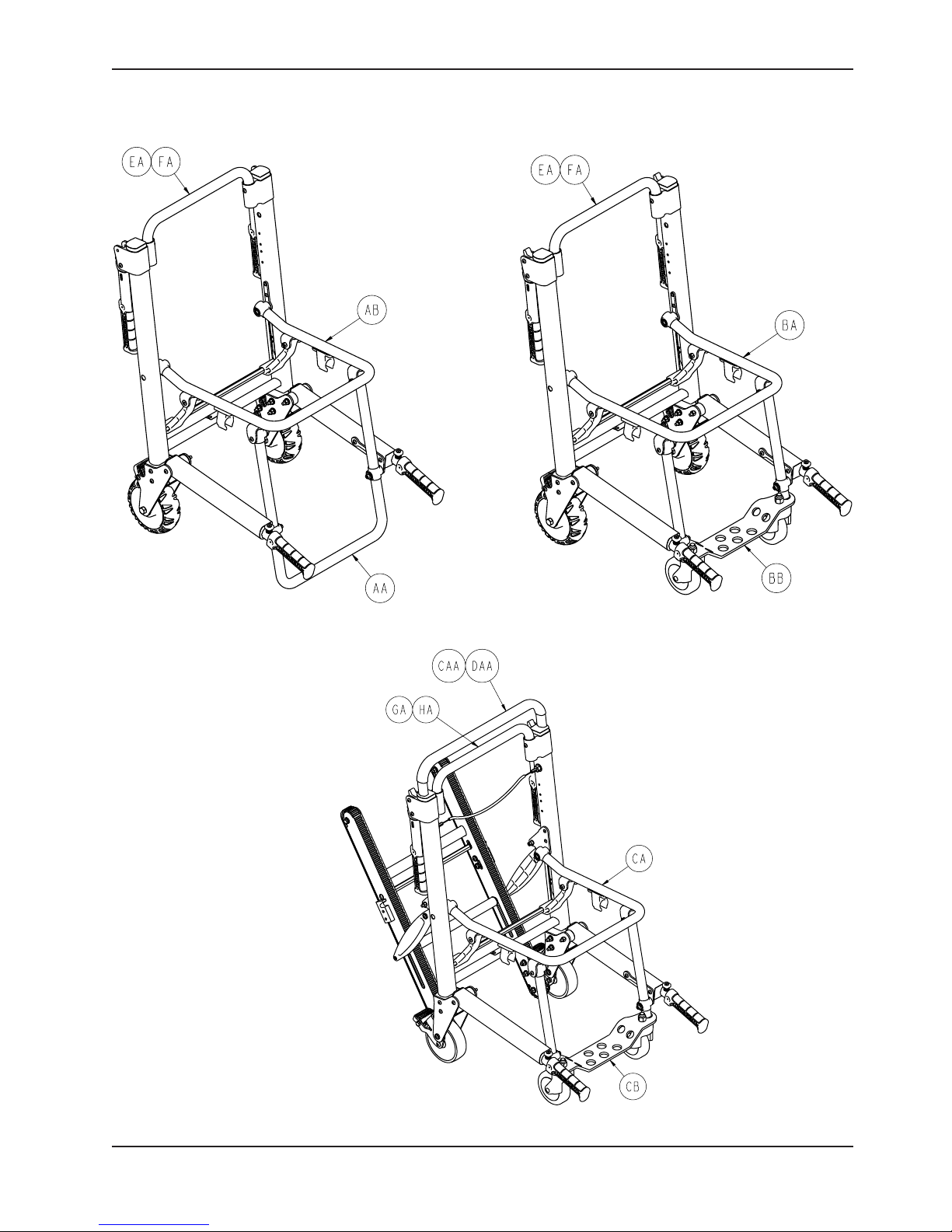
MODEL 6250 - 6250-001-010 Rev B (Reference Only)
Item Part No. Part Name Qty.
AA 6250-001-012 Foot Tube Assembly (page 61) 1
AB 6250-001-020 Common Components 1
AC 6250-001-137 Label, 6250 Specification 1
MODEL 6251 - 6251-001-010 Rev B (Reference Only)
Item Part No. Part Name Qty.
BA 6250-001-020 Common Components 1
BB 6251-001-012 Foot Support Assembly (page 62) 1
BC 6251-001-137 Label, 6251 Specification 1
MODEL 6252 - 6252-001-010 Rev C (Reference Only)
Item Part No. Part Name Qty.
CA 6250-001-020 Common Components 1
CB 6251-001-012 Foot Support Assembly (page 62) 1
CC 6252-001-137 Label, 6252 Specification 1
CD 6252-001-138 Label, Track Release 1
CE 6252-001-139 Label, “Do Not Lubricate” 2
www.stryker.com 6250 -001-160 REV E 47
Return To Table of Contents
Page 48

Chair Assembly
6250/6251 Main Frame Assembly Option - 6250-022-000 (Rev A)
Item Part No. Part Name Qty.
EA 6250-001-011 Main Frame Assembly (page 49) 1
6250 Extended Main Frame Assembly Option - 6250-023-000 (Rev A)
Item Part No. Part Name Qty.
FA 6250-003-011 Main Frame Assembly, Extended 1
6252 Main Frame Assembly Option - 6252-022-000 (Rev A)
Item Part No. Part Name Qty.
GA 6252-001-011 Main Frame Assembly (page 50) 1
6252 Extended Main Frame Assembly Option - 6252-023-000 (Rev A)
Item Part No. Part Name Qty.
HA 6252-003-011 Main Frame Assembly, Extended 1
6252 No I.V. Bag Clip Option - 6252-024-000 (Rev A)
Item Part No. Part Name Qty.
CAA 6252-001-012 Upper Extension Handle 1
6252 I.V. Bag Clip Option - 6252-025-000 (Rev A)
Item Part No. Part Name Qty.
DAA 6252-001-212 I.V. Clip Upper Extension Handle 1
DAB 6252-001-153 I.V. Strap 1
Return To Table of Contents
48 6250-001-160 REV E www.stryker.com
Page 49

6250/6251 Main Frame Assembly
6250-001-011 Rev F (Reference Only)
Item Part No. Part Name Qty.
A 0003-033-000 Hex Head Cap Screw 2
B 0004-235-000 Button Head Cap Screw 6
C 0004-511-000 Button Head Cap Screw 2
D 0015-016-000 Square Nut 2
E 0025-172-000 Blind Rivet 8
F 0016-139-000 Nylock Nut 2
G 0016-028-000 Nylock Hex Nut 6
H 6060-002-010 Wheel Assembly (page 59) 2
J 6080-300-030 Adjustable Caster Lock Pedal 2
K 6080-200-041 Hex Sleeve 2
L 6250-001-055 Frame Weldment 1
M 6250-001-086 Outer Extrusion End Cap 2
N 6250-001-102 Outer Wheel Supt. Spacer 2
P 6250-001-103 Inner Wheel Supt. Spacer 2
R 6250-001-104 Wheel Support 4
S 6250-001-118 Lock Retaining Spring 2
T 6250-001-131 Spring 2
U 6250-001-132 Seat Spacer 2
V 6250-001-134 Rivet Back Plate 2
W 0025-079-000 Blind Rivet 4
Y 0011-209-000 Washer 6
Return To Table of Contents
www.stryker.com 6250 -001-160 REV E 49
Page 50

6252 Main Frame Assembly
6252-001-011 Rev J (Reference Only)
Return To Table of Contents
50 6250 -0 01-160 REV E ww w.stryker.com
Page 51

6252 Main Frame Assembly
www.stryker.com 6250 -001-160 REV E 51
Return To Table of Contents
Page 52

6252 Main Frame Assembly
6252 Main Frame Assembly Components - 6252-001-011 Rev J (Reference Only)
Item Part No. Part Name Qty.
A 0004-235-000 Button Head Cap Screw 4
B 0004-468-000 Button Head Cap Screw 4
C 0004-511-000 Button Head Cap Screw 2
D 0004-512-000 Button Head Cap Screw 2
E 0025-079-000 Blind Rivet 4
F 0004-514-000 Socket Head Cap Screw 2
G 0011-045-000 Washer 4
H 0011-209-000 Washer 10
J 0011-423-000 Spacer 4
K 0011-455-000 Washer 2
P 0015-016-000 Square Nut 2
R 0016-028-000 Nylock Nut 8
S 0016-316-000 Centerlock Hex Jam Nut 2
T 0025-172-000 Blind Rivet 4
U 6250-001-055 Frame Weldment 1
V 6250-001-102 Wheel Support Spacer, Outer 2
W 6250-001-103 Wheel Support Spacer, Inner 2
X 6250-001-118 Lock Retaining Spring 2
Z 6252-001-013 Track Frame Assembly (page 54) 1
AA 6252-001-016 Cable and Pin Assembly (page 58) 1
AB 6252-001-084 Track Belt Roller Spacer 2
AC 6252-001-124 Track Supt. Offset Bracket 1
AD 6252-001-125 Track Supt. Offset Bracket 1
AE 6252-001-088 Track Support Strut 2
AF 6252-001-089 Track Support Cross Bar 1
AG 6252-001-094 Upper Extension Handle Dead Stop 2
AH 6252-001-096 Track Lock Post 2
AJ 6252-001-104 Wheel Support 4
AK 6252-001-106 Track Spacer Pivot 4
AL 6252-001-113 Track Tube Spacer 1
AM 6252-001-114 5” Wheel 2
AN 6252-001-120 Track Sleeve Spacer 2
AR 0004-028-000 Socket Head Cap Screw 2
AS 0004-204-000 Button Head Cap Screw 2
AT 0011-064-000 Washer 4
AV 6250-001-124 Flange Bearing 2
Return To Table of Contents
52 6250- 001-160 REV E w ww.stryker.com
Page 53

Upper Control Handle Assembly - 6252-001-012
Rev B
Item Part No. Part Name Qty.
A 0025-133-000 Blind Rivet 4
B 6250-001-085 Internal Slide Bushing 2
C 6250-001-087 Outer Extension Handle Bushing 2
D 6252-001-090 Upper Internal Handle 1
E 6252-001-145 Handle Reinforcer 2
www.stryker.com 6250 -001-160 REV E 53
Return To Table of Contents
Page 54

6252 Track Frame Assembly, Standard Belt
6252-001-013 Rev E (Reference Only)
Return To Table of Contents
54 6250 -001-160 REV E www.stryker.com
Page 55

6252 Track Frame Assembly, Standard Belt
6252 Track Frame Assembly, Standard Belt - 6252-001-013 Rev E (Reference Only)
Item Part No. Part Name Qty.
A 0003-358-000 Hex Head Cap Screw 2
B 0003-365-000 Hex Head Cap Screw 2
D 0004-483-000 Button Head Cap Screw 4
E 0004-511-000 Button Head Cap Screw 8
F 0008-063-000 Socket Head Cap Screw 2
G 0011-209-000 Washer 14
H 0014-099-000 Washer 2
J 0016-028-000 Hex Nut 8
L 0025-172-000 Blind Rivet 4
M 6080-300-030 Adjustable Caster Lock Pedal 2
N 6080-200-041 Hex Sleeve 2
P 6252-001-014 Internal Latch Assembly (page 56) 1
R 6252-001-015 Internal Latch Assembly (page 57) 1
S 6252-001-050 Track Frame Weldment 1
T 6252-001-083 Track Belt Roller 4
U 6252-001-084 Track Belt Roller Spacer 4
V 6252-001-085 Track Belt 2
W 6252-001-102 Wheel Support Stamping 1
X 6252-001-103 Wheel Support Stamping 1
Y 6252-001-105 Lock Mechanism Cross Bar 1
Z 6252-001-110 Latch 1
AA 6252-001-111 Latch 1
BB 6252-001-112 Spring 4
CC 6252-001-121 Lock Pivot Internal Spacer 2
www.stryker.com 6250 -001-160 REV E 55
Return To Table of Contents
Page 56

6252-001-014 Rev B (Reference Only)
Internal Latch Assembly
Item Part No. Part Name Qty.
A 0014-098-000 Washer 1
B 0038-506-000 Compression Spring 1
C 6252-001-097 Latch Retainer Block 1
D 6252-001-098 Latch Release Slide 1
E 6252-001-099 Track Latch Lock 1
F 6252-001-101 Single Spring 1
Return To Table of Contents
56 6250 -001-160 REV E www.stryker.com
Page 57

6252-001-015 Rev B (Reference Only)
Internal Latch Assembly
Item Part No. Part Name Qty.
A 0014-098-000 Washer 1
B 0038-506-000 Compression Spring 1
C 6252-001-097 Latch Retainer Block 1
D 6252-001-098 Latch Release Slide 1
E 6252-001-099 Track Latch Lock 1
F 6252-001-100 Single Spring 1
www.stryker.com 6250 -001-160 REV E 57
Return To Table of Contents
Page 58

Cable and Pin Assembly - 6252-001-016
Rev B
Item Part No. Part Name Qty.
A 0038-507-000 Compression Spring 2
B 6252-001-115 Pull Pin 2
C 6252-001-116 Pull Pin Bolt 2
D 6252-001-119 Cable 1
Return To Table of Contents
58 6250 -0 01-160 REV E ww w.stryker.com
Page 59

Wheel Assembly - 6060-002-010
Rev B
Item Part No. Part Name Qty.
A 6060-002-045 6” Molded Wheel 1
B 6060-002-046 Bearing Spacer 1
C 0081-226-000 Bearing 2
D 0715-001-255 Wheel Bushing 2
Return To Table of Contents
www.stryker.com 6250 -001-160 REV E 59
Page 60

6250/6251/6252 Locking Flip-Up Handle Option
6250-031-000 Rev E (Reference Only)
Item Part No. Part Name Qty.
PA 0004-204-000 Button Head Cap Screw 2
PB 0016-028-000 Nylock Nut 2
PC 6250-001-111 Flip-Up Handle Pivot Spacer 2
PD 6250-001-113 Flip-Up Handle Trigger 2
PE 6250-001-114 Single Spring 2
Return To Table of Contents
60 6250 -0 01-160 REV E www.stryker.com
Page 61

6250 Foot Tube Assembly - 6250-001-012
Rev A
Item Part No. Part Name Qty.
A 6250-001-090 Foot Section End Cap 2
B 6250-001-091 Foot Section Tube 1
C 6250-001-096 Foot/Seat Section End Cap 2
Return To Table of Contents
www.stryker.com 6250 -001-160 REV E 61
Page 62

6251/6252 Foot Support Assembly - 6251-001-012
Rev A
Item Part No. Part Name Qty.
A 0016-064-000 Nylock Hex Nut 2
B 6250-001-090 Foot Section End Cap 2
C 6250-001-096 Foot/Seat Section End Cap 2
D 6251-001-050 Foot Section Weldment 1
E 6251-001-083 Caster 2
Return To Table of Contents
62 6250 -001-160 REV E www.stryker.com
Page 63

6250/6251/6252 Standard Lower Lift Handle/No Foot Rest
Lower Lift Handle Option - 6250-024-000 (Rev C)
Item Part No. Part Name Qty.
JB 6250-001-014 Extension Handle, Right 1
JC 6250-001-015 Extension Handle, Left 1
JE 6250-001-129 Pivot Spacer 2
JF 6250-001-133 Spacer 2
www.stryker.com 6250 -001-160 REV E 63
No Foot Rest Option - 6252-028-000 (Rev C)
Item Part No. Part Name Qty.
YD 6250-001-098 Pivot Spacer 2
Return To Table of Contents
Page 64

6250/6251/6252 Extended Lower Lift Handle Option
6250-025-000 Rev C (Reference Only)
Item Part No. Part Name Qty.
KB 6250-003-014 Extension Extended Handle, Right 1
KC 6250-003-015 Extension Extended Handle, Left 1
KE 6250-003-129 Pivot Spacer 2
KF 6250-003-133 Spacer, Extension Handle Locator 2
KG 6250-003-134 Spacer, Extension Handle Locator 2
Return To Table of Contents
64 6250 -001-160 REV E www.stryker.com
Page 65

Extension Handle Assembly, Right - 6250-001-014
Rev E
Item Part No. Part Name Qty.
A 0001-138-000 Flat Head Socket Screw 1
B 0004-136-000 Button Head Cap Screw 1
C 0004-509-000 Button Head Cap Screw 3
D 0015-016-000 Square Nut 1
E 0025-079-000 Blind Rivet 2
F 0025-132-000 Blind Rivet 2
G 0026-323-000 Coiled Spring Pin 1
H 0038-462-000 Compression Spring 1
J 0056-022-000 Bumper 1
K 6100-031-065 Push Button 1
L 6250-001-080 Pivot Lock Lever 1
M 6250-001-081 Internal Extension Handle 1
N 6250-001-082 Pivot Bracket 1
P 6250-001-083 Lock Pin 1
R 6250-001-085 Internal Slide Bushing 1
S 6250-001-086 Outer End Cap 1
T 6250-001-087 Outer Bushing 1
U 6250-001-089 Hand Grip 1
V 6250-001-112 Dead Stop 1
W 6250-001-121 Extension Outer Handle, Right 1
www.stryker.com 6250 -001-160 REV E 65
Return To Table of Contents
Page 66

Extension Handle Assembly, Left - 6250-001-015
Rev E
Item Part No. Part Name Qty.
A 0001-138-000 Flat Head Socket Screw 1
B 0004-136-000 Button Head Cap Screw 1
C 0004-509-000 Button Head Cap Screw 3
D 0015-016-000 Square Nut 1
E 0025-079-000 Blind Rivet 2
F 0025-132-000 Blind Rivet 2
G 0026-323-000 Coiled Spring Pin 1
H 0038-462-000 Compression Spring 1
J 0056-022-000 Bumper 1
K 6100-031-065 Push Button 1
L 6250-001-080 Pivot Lock Lever 1
M 6250-001-081 Internal Extension Handle 1
N 6250-001-082 Pivot Bracket 1
P 6250-001-083 Lock Pin 1
R 6250-001-085 Internal Slide Bushing 1
S 6250-001-086 Outer End Cap 1
T 6250-001-087 Outer Bushing 1
U 6250-001-089 Hand Grip 1
V 6250-001-112 Dead Stop 1
W 6250-001-122 Extension Outer Handle, Left 1
Return To Table of Contents
66 6250 -0 01-160 REV E www.stryker.com
Page 67
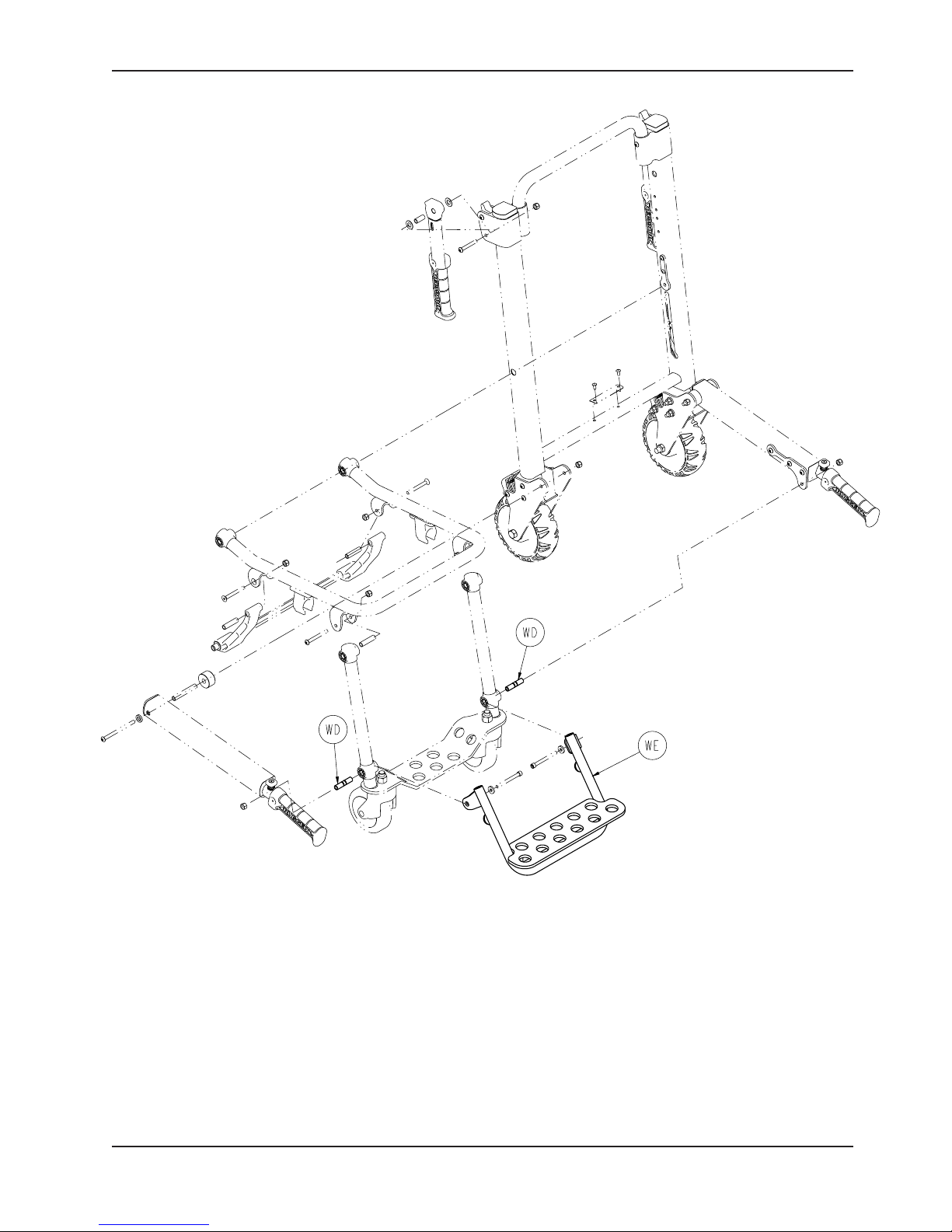
6251/6252 Foot Rest Option
6252-027-000 Rev B (Reference Only)
Item Part No. Part Name Qty.
WD 6250-003-098 Pivot Spacer 2
WE 6252-001-017 Foot Support Assembly 1
www.stryker.com 6250 -001-160 REV E 67
Return To Table of Contents
Page 68

6252 Extended Handle/No Foot Rest Option
6252-030-000 Rev C (Reference Only)
Item Part No. Part Name Qty.
BAD 6250-003-098 Pivot Spacer 2
Return To Table of Contents
68 6250 -0 01-160 REV E www.stryker.com
Page 69

6252 Extended Handle/Foot Rest Option
6252-029-000 Rev B (Reference Only)
Item Part No. Part Name Qty.
AAD 6250-003-099 Pivot Spacer 2
AAE 6252-001-017 Foot Support Assembly 1
www.stryker.com 6250 -001-160 REV E 69
Return To Table of Contents
Page 70

Seat Section Assembly - 6250-001-013
Rev B
Item Part No. Part Name Qty.
A 0025-120-000 Rivet 4
B 6250-001-165 Clip 2
C 6250-001-050 Seat Frame Weldment 1
D 6250-001-096 Foot/Seat Section End Cap 2
Return To Table of Contents
70 625 0- 001-160 RE V E www.stryker.com
Page 71

Flip-Up Handle Assembly - 6250-001-016
Rev A
Item Part No. Part Name Qty.
A 0025-132-000 Blind Rivet 2
B 6250-001-052 Flip-Up Handle Weldment 1
C 6250-001-089 Hand Grip 1
Return To Table of Contents
www.stryker.com 6250 -001-160 REV E 71
Page 72

Lock Mechanism Assembly - 6250-001-017
Rev B
Item Part No. Part Name Qty.
A 0004-515-000 Button Head Cap Screw 4
B 6250-001-094 Strut 2
C 6250-001-095 Cross Bar 1
D 6250-001-124 Flange Bearing 2
Return To Table of Contents
72 625 0- 001-160 RE V E www.stryker.com
Page 73

6250/6251/6252 Vinyl Seat Option
6250-020-000 Rev E (Reference Only)
Item Part No. Part Name Qty.
LA 0004-517-000 Socket Head Cap Screw 2
LB 0011-064-000 Washer 2
LC 0011-209-000 Washer 2
LD 0016-028-000 Nylock Hex Nut 2
LE 6250-001-098 Pivot Spacer 2
LF 6250-001-135 Vinyl Seat 1
www.stryker.com 6250 -001-160 REV E 73
Return To Table of Contents
Page 74

6250/6251/6252 ABS Seat Option
6250-021-000 Rev D (Reference Only)
Item Part No. Part Name Qty.
MA 0004-517-000 Socket Head Cap Screw 2
MB 0011-064-000 Washer 2
MC 0011-209-000 Washer 2
MD 0016-028-000 Nylock Hex Nut 2
ME 0025-172-000 Blind Rivet 16
MF 6250-001-099 Seat Support Bracket 1
MG 6250-001-115 Plastic Seat 1
MH 6250-001-116 Plastic Back Rest 1
MJ 6250-001-128 Pivot Spacer 2
Return To Table of Contents
74 6250 -001-160 REV E www.stryker.com
Page 75

Seat and Back Rest Options
ABS SEAT - 6250-001-115 (Rev C)
ABS SEAT OPTION - 6250-021-000 (Rev D)
ABS BACKREST - 6250-001-116 (Rev C)
www.stryker.com 6250 -001-160 REV E 75
VINYL SEAT - 6250-001-135 (Rev B)
VINYL SEAT OPTION - 6250-020-000 (Rev E)
Return To Table of Contents
Page 76

6252 Head Support Options
6252-001-122 Rev B (Reference Only)
6252-001-140 Rev B (Reference Only)
Head Support Option - 6250-040-000 (Rev B)
Item Part No. Part Name Qty.
SA 6252-001-122 Head Support 1
Vinyl Head Support Option - 6250-041-000 (Rev B)
Item Part No. Part Name Qty.
TA 6252-001-140 Vinyl Head Support 1
Return To Table of Contents
76 6250- 001-160 RE V E www.stryker.com
Page 77

Restraint Set, Non-Absorbent/Metal Buckles Option
6250-161-000 Rev B (Reference Only)
56” 15”
Fully Extended
Vinyl Restraint Strap Set - 6250-001-019 (Rev A)
54”
Fully Extended
Item Part No. Part Name Qty.
A 6250-001-143 Vinyl Chest Restraint Strap 2
B 6250-001-144 Vinyl Ankle Restraint Strap 1
Restraint Set, Polyester/Metal Buckles Option
6250-162-000 Rev B (Reference Only)
55”
Fully Extended
25.25”
Item Part No. Part Name Qty.
A 6060-160-044 Lap Belt Assembly 2
B 6250-001-127 Ankle Restraint Strap 1
C 6250-001-163 Restraint Buckle 2
www.stryker.com 6250 -001-160 REV E 77
54”
Restraint Strap Set - 6250-001-021 (Rev B)
Return To Table of Contents
Page 78

Restraint Set, Polypropylene/Plastic Buckles Option
6250-160-000 Rev D (Reference Only)
15”
56”
15”
56”
54”
Restraint Strap Set - 6250-001-022 (Rev A)
Item Part No. Part Name Qty.
A 6250-001-018 Restraint Strap Set 1
B 6250-001-163 Restraint Buckle 2
Return To Table of Contents
78 625 0- 001-160 REV E w ww.stryker.com
Page 79

Optional Vinyl Head Support - 6252-001-140
10.00”
Rev B
36.25”
www.stryker.com 6250 -001-160 REV E 79
Return To Table of Contents
Page 80

Elastic Oxygen Bottle Holder - 6250-140-000
Rev A
Return To Table of Contents
80 6250 -0 01-160 REV E www.stryker.com
Page 81

Page 82

United States
Stryker Medical
3800 E. Centre Ave.,
Portage, Michigan USA
49002
EC REP
European Representative
Stryker France
ZAC Satolas Green Pusignan
Av. De Satolas Green
69881 MEYZIEU Cedex
France
2011/03 6250-001-160 REV E www.stryker.com
 Loading...