

Stryker Stair-PRO 6250, Stair-PRO Series, Stair-PRO 6251, Stair-PRO 6252 Operation & Maintenance Manual
Page 1
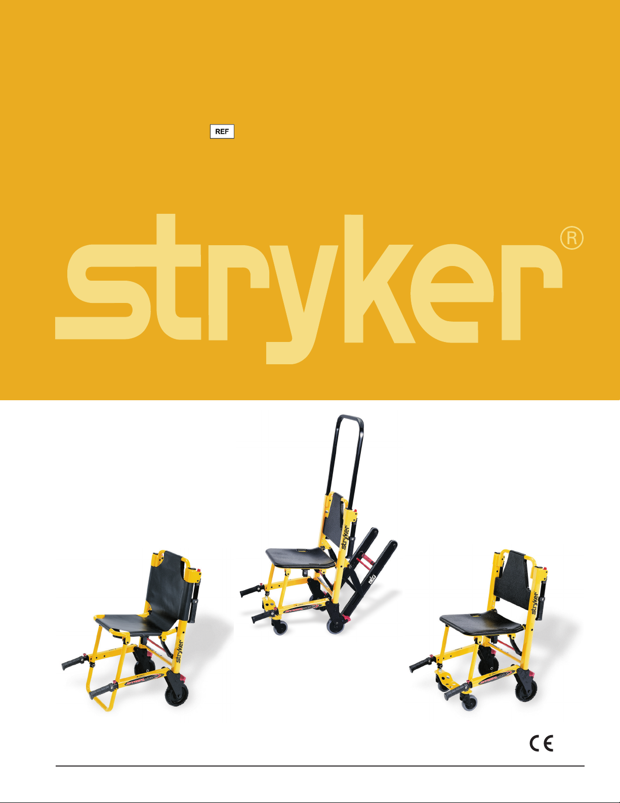
Stair-PRO
Stair Chair/Chaise-civière/Treppenrollstuhl
Trapstoel/Sedia portantina/Silla para escaleras
Cadeira para escada/Trappstol/Trappestol/Porrastuoli
Αμαξίδιο για σκάλες/Krzesło do przenoszenia po schodach
Model/Modèle/Modell/Modello/Modelo/Malli/Μοντέλο
6250/6251/6252
®
Operations/Maintenance Manual
Manuel d’utilisation et d’entretien
Bedienungs- und Wartungshandbuch
Gebruiks-/onderhoudshandleiding
Manuale d’uso e manutenzione
Manual de uso y mantenimiento
Manual de funcionamento/manutenção
Betjenings-/vedligeholdelsesmanual
Användar-/underhållshandbok
Käyttö- ja huolto-ohjekirja
Εγχειρίδιο λειτουργίας/συντήρησης
Instrukcja obsługi / konserwacji
6252
6250
2011/03 6250-001-161 REV D.2 www.stryker.com
6251
Page 2

Page 3

International Addresses
FINLAND
Stryker AB, Finland
PO 80 Makelankatu 2
EUROPE HEADQUARTERS
Stryker SA
Cite-Centre, Grand-Rue 90
P.O. Box 1568
1820 Montreux, Switzerland
Phone: 011-41-21-966-12-01
Fax: 011-41-21-966-12-00
EASTERN EUROPE
Stryker SA - Export Business
Grand-Rue 90
P.O. Box 1567
1820 Montreux, Switzerland
Phone: 011-41-21-966-14-00
Fax: 011-41-21-966-14-01
AUSTRIA
Stryker-Howmedica Osterreich GmbH
Millenium Tower
Handelskai 94-96
120 Wien
Austria
Phone: 011-43-1-240 -27-6400
Fax: 011-43-1-240-27-6410
BELGIUM
NV Stryker SA
Ikaros Business Park- Fase III
Ikaroslaan 12
1930 Zaventem, Brussels
Belgium
Phone: 011-32-2-717-9210
Fax: 011-32-2-717-9249
DENMARK
Stryker Denmark
Filial of Stryker AB
Postbox 772
1532 Copenhagen
Denmark
Phone: 011-45-33-93-6099
Fax: 011-45-33-93-2069
ENGLAND
Stryker UK Limited
Stryker House
Hambridge Road
Newbury, Berkshire
RG14 5EG, England
Phone: 011-44-1635-556-500
Phone: 011-44-1635-262-400
Fax: 011-44-1635-580-300
00501 Helsinki
Finland
Phone: 011-35-89-774-4680
Fax: 011-35-89-774-46820
FRANCE
Stryker France SA
ZAC - Avenue de Satolas Green
69330 Pusignan
France
Phone: 011-33-472-45-36-00
Fax: 011-33-472-45-36-99
GERMANY
Stryker Howmedica GmbH
Dr. Homer Stryker Platz 1
47228 Duisburg
Germany
Phone: 011-49-2065-837-0
Fax: 011-49-2065-837-837
GREECE
Stryker Hellas EPE
455 Messogion ave
153 43 Agia Paraskevi
Athens, Greece
Phone: 011-30-2-10-600-32-22
Fax: 011-30-2-10-600-48-12
ITALY
Stryker Italia SrL
Via Ghisalba 15B
00188 Roma
Italy
Phone: 011-39-06-33-05-41
Fax: 011-39-06-33-614-067
MIDDLE EAST / NORTH AFRICA
Stryker Osteonics SA
Twin Towers
11th Floor, Suite 1101 & 1102
P.O. Box 41446
Baniyas Road
Dubai, Deira, UAE
Phone: 011-97-14-222-2842
Fax: 011-97-14-224-7381
NEDERLANDS
Stryker Nederlands BV
(P.O. Box 13, 4180 BA Waardenburg)
4181 CD Waardenburg
The Nederlands
Phone: 011-31-418-569-700
Fax: 011-31-418-569-777
NORWAY
Stryker Norway
Norsk Fillial
Nedre Vollgate 3
0158 Oslo
Norway
Phone: 011-47-22-42-22-44
Fax: 011-47-22-42-22-54
POLAND
Stryker Polska Sp. ZO.O
Kolejowa 5/7
01-217 Warsawa
Poland
Phone: 011-48-22-434-88-50
Fax: 011-48-22-434-88-60
PORTUGAL
Stryker Portugal Produtos
Medicos, LTDA.
Avenida Marechal Gomes
da Costa, 35
1800-255 Lisboa
Portugal
Phone: 011-35 -1-21-839-49-10
Fax: 011-35-1-21-839-49-19
ROMANIA
Stryker Osteonics Romania S.R.L.
19, Leonida Str.
District 2
7000 Bucharest
Romania
Ph one: 011-40-2-12-12-11-22
Fa x: 011- 4 0 -2-12-12-11-3 3
SOUTH AFRICA
Stryker Osteonis PTY. LTD.
3 Susan Street
Strydom Park
Johannesburg, 2194 - South Africa
Mailing Address:
P.O. Box 48039
2129 Roosevelt Park
Johannesburg, South Africa
Phone: 011-27-11-791-4644
Fax: 011-27-11-791-4696
SPAIN
Stryker Howmedica Iberica S.L.U.
Manual Tovar, 35
28034 Madrid
Spain
Phone: 011-34-91-728-35-00
Phone: 011-34-91-358-20-44
Fax: 011-34-91-358-07-48
SWEDEN
Stryker AB/Scandinavia
Box 50425
SE-204 14 Malmo
Sweden
Phone: 011-46-40-691-81-00
Fax: 011-46-40-691-81-91
Page 4

Page 5

Table of Contents
Symbols and Definitions ...................................................................1-4
Symbols ...........................................................................1- 4
Warning / Caution / Note Definition........................................................1-4
Introduction ............................................................................1-5
Specifications .......................................................................1-5
Component Identification ...............................................................1-6
Warranty ..............................................................................1-7
Stryker EMS Return Policy ..............................................................1- 8
Return Authorization...................................................................1-8
Damaged Merchandise ................................................................1-8
International Warranty Clause............................................................1- 8
Patent Information ....................................................................1-8
Summary of Safety Precautions .............................................................1-9
Setup Procedures.......................................................................1-10
Operation Guide........................................................................1-1 1
Operating Guidelines ................................................................1-11
Unfolding the Chair ..................................................................1-12
Folding the Chair ....................................................................1-13
Transferring the Patient to the Stair-PRO® Stair Chair .........................................1-14
Using Restraint Straps ................................................................1-15
Proper Lifting Techniques..............................................................1-18
Transporting the Patient on Flat Surfaces ..................................................1-19
Transporting the Patient Down Stairs .....................................................1-2 0
Transporting the Patient Up Stairs .......................................................1-23
Operating the Wheel Locks ............................................................1-24
Adjusting the Wheel Locking Force.......................................................1-25
Operating the Optional Locking Rear Lift Handles ............................................1-26
Using the Optional Head Support (Model 6252 Only) .........................................1-2 7
Using Additional Assistance ............................................................1-2 8
Cleaning..............................................................................1-2 9
Washing Procedure ..................................................................1-29
Washing Limitations ..................................................................1-29
Preventative Maintenance .................................................................1-31
Checklist ..........................................................................1-31
Maintenance Record.....................................................................1-3 2
Training Record ........................................................................1-33
Quick Replacement Part List...............................................................1-34
Service Information......................................................................1-3 5
Vinyl Seat Replacement...............................................................1-35
Track Belt Replacement (For Model 6252) .................................................1-36
Track Belt Reconditioning (For Model 6252) ................................................1-39
Rear Wheel Replacement..............................................................1-41
Upper Control Handle Cable Replacement (For Model 6252)....................................1-42
English
www.stryker.com 6250 -001-161 REV D 1- 3
Page 6
English
Symbols and Definitions
SYMBOLS
Warning/Caution: consult accompanying documentation
Safe Working Load
WARNING / CAUTION / NOTE DEFINITION
The words WARNING, CAUTION and NOTE carry special meanings and should be carefully reviewed.
WARNING
Alerts the reader about a situation, which if not avoided, could result in death or serious injury. It may also describe
potential serious adverse reactions and safety hazards.
CAUTION
Alerts the reader of a potentially hazardous situation, which if not avoided, may result in minor or moderate injury to the
user or patient or damage to the equipment or other property. This includes special care necessary for the safe and
effective use of the device and the care necessary to avoid damage to a device that may occur as a result of use or
misuse.
NOTE
This provides special information to make maintenance easier or important instructions clearer.
Return To Table of Contents
1-4 6 250-001-161 REV D www.stryker.com
Page 7
Introduction
INTRODUCTION
This manual is designed to assist you with the operation and maintenance of the Model 6250, 6251, and 6252 StairPRO® Stair Chairs. Read it thoroughly before using the equipment or beginning any maintenance on it.
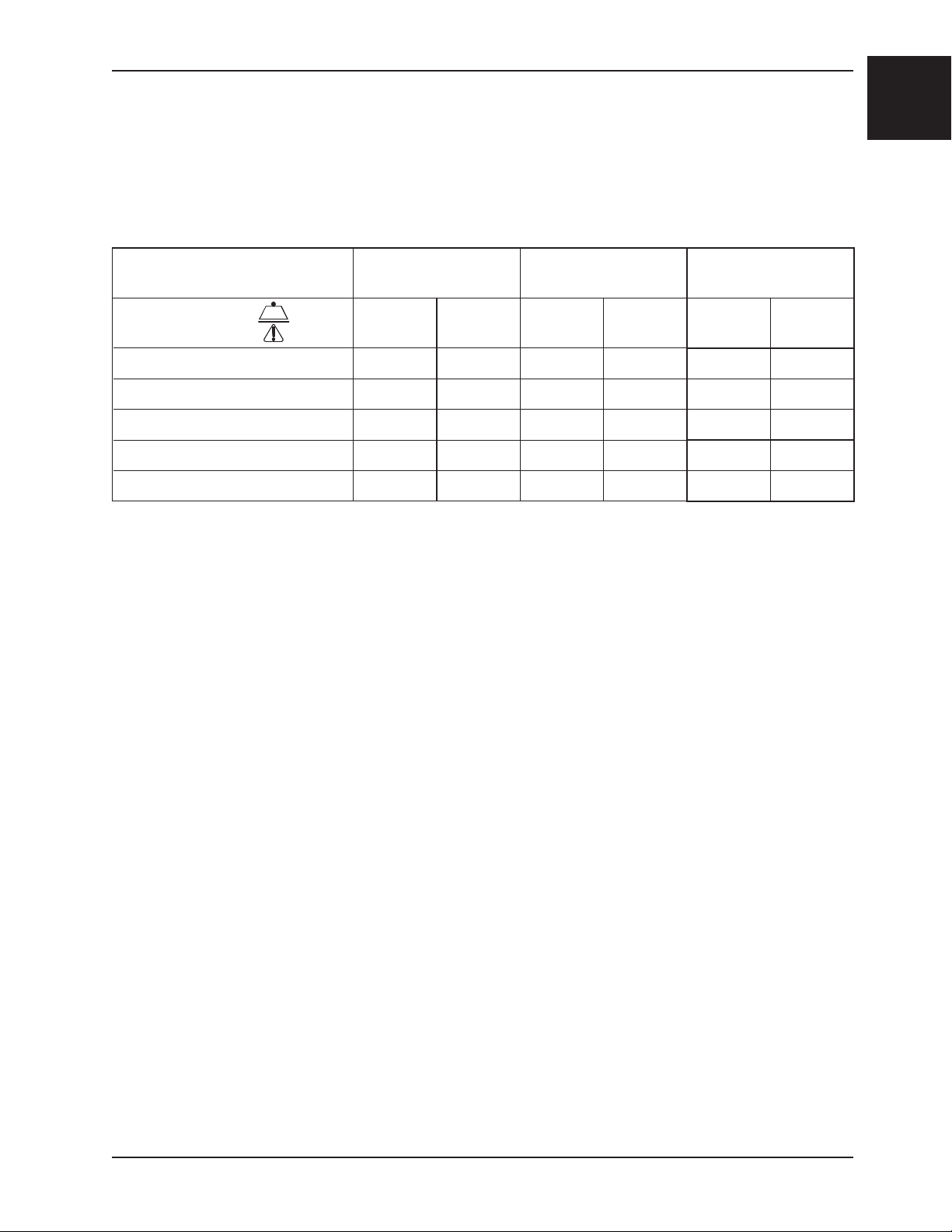
SPECIFICATIONS
English
Model
Maximum Load
3
500 lbs. 228 kg. 500 lbs. 228 kg. 500 lbs. 228 kg.
6250 6251 6252
Height 36” 91 cm. 36” 91 cm. 37.5” 95.25 cm.
Width 20.5” 52 cm. 20.5” 52 cm. 20.5” 52 cm.
2
Depth
28” 71 cm. 28” 71 cm. 28” 71 cm.
Folded Depth 8” 20 cm. 8” 20 cm. 8” 20 cm.
Weight 20 lbs. 9 kg. 23 lbs. 10 kg. 31.5 lbs. 14 kg.
1
Dimensions are measured from the outermost edges of the main frame. Specifications are rounded. Conversions are calculated
before rounding.
2
Depth dimensions are measured with extendable handles retracted.
3
Maximum load capacity is total weight distributed in accordance to basic human anatomy. Operators must consider the weight
of the patient, equipment, and accessories when determining the total load on the product.
Stryker reserves the right to change specifications without notice.
Return To Table of Contents
www.stryker.com 6250 -001-161 REV D 1- 5
Page 8
English
Lift Handles
Introduction
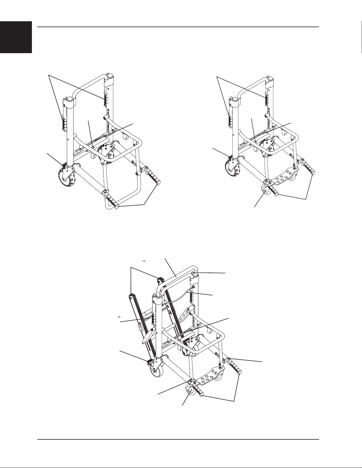
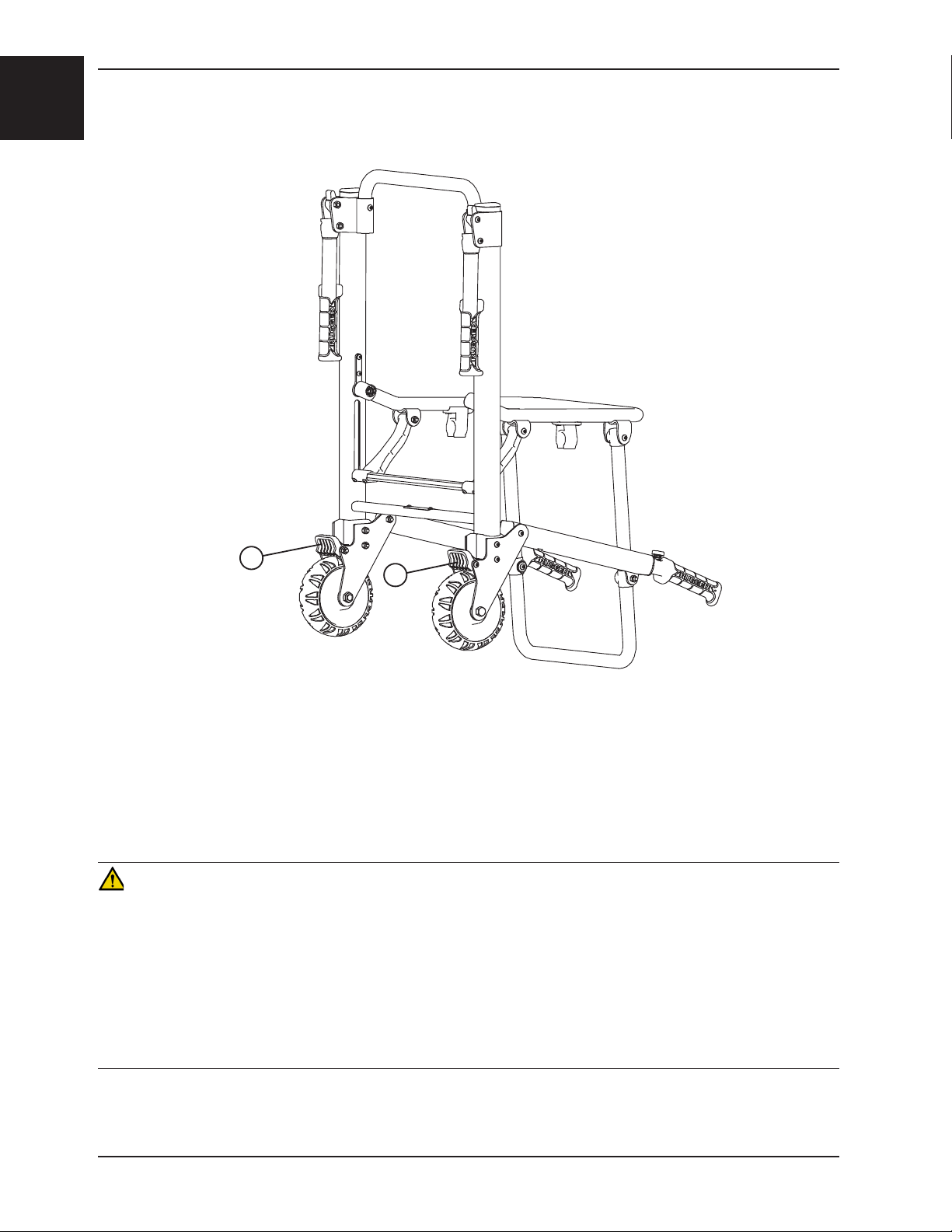
COMPONENT IDENTIFICATION
Head End
Lift Handles
Wheel Lock
Serial
Number
Location
6250
Chair Fold
Lock Bar
Foot End
Lift Handles
Wheel Lock
Head End
Serial
Number
Location
Front Caster
6251
Chair Fold
Lock Bar
Foot End
Lift Handles
Stair−TREAD
Stair−TREAD
Lock Bar
Wheel Lock
Control Handle
Lift Handle
Release Button
Upper
Front Caster
6252
Optional Lift Handles
Release Lever
Upper Control Handle
Release Cable
Chair Fold
Lock Bar
Lift Handle
Release Button
Foot End
Lift Handles
Return To Table of Contents
1-6 6 250-001-161 REV D www.stryker.com
Page 9
Warranty
Stryker EMS, a division of the Stryker Corporation, offers two distinct warranty options in the
United States:
One (1) year parts and labor. Under this option, Stryker EMS warrants to the original purchaser
that its products should be free from manufacturing non-conformances that affect product
performance and customer satisfaction for a period of one (1) year after date of delivery. Stryker’s
obligation under this warranty is expressly limited to supplying replacement parts and labor for, or
replacing, at its option, any product that is, in the sole discretion of Stryker, found to be defective.
Two (2) year parts. Under this option, Stryker EMS warrants to the original purchaser that nonexpendable components of its products should be free from manufacturing non-conformances
that affect product performance and customer satisfaction for a period of two (2) years after date
of delivery. Stryker’s obligation under this warranty is expressly limited to supplying replacement
parts for, or replacing, at its option, any product which is, in the sole discretion of Stryker, found to
be defective. Expendable components, i.e. mattresses, restraints, IV poles, storage nets, storage
pouches, O2 straps, and other soft goods, have a one (1) year limited warranty with this option.
Under either warranty option, Stryker EMS products are designed for a 7 year expected service
life under normal use, conditions, and with appropriate periodic maintenance as described
in the maintenance manual for each device. Stryker warrants to the original purchaser
that the welds on its EMS products will be free from structural defects for the expected 7
year life of the EMS product as long as the original purchaser owns the product. Original
purchasers will also obtain a three (3) year limited parts warranty for the X-frame components
of the MX-PRO R3 stretcher provided they also purchase X-frame guards at the time of the
original purchase and the guards are installed on the MX-PRO before it is put into service.
If Stryker requests, products or parts for which an original purchaser makes a warranty
claim, the purchaser shall return the product or part prepaid freight to Stryker’s factory.
Any improper use or alteration or repair by unauthorized service providers in such a manner as
in Stryker’s judgment affects the product materially and adversely, shall void this warranty. Any
repair of Stryker products using parts not provided or authorized by Stryker shall void this warranty.
No employee or representative of Stryker is authorized to change this warranty in any way.
This statement constitutes Stryker EMS’s entire warranty with respect to the aforesaid equipment.
STRYKER MAKES NO OTHER WARRANTY OR REPRESENTATION EITHER EXPRESSED OR
IMPLIED, EXCEPT AS SET FORTH HERIN. THERE IS NO WARRANTY OF MERCHANTABILITY
AND THERE ARE NO WARRANTIES OF FITNESS FOR ANY PARTICULAR PURPOSE. IN NO
EVENT SHALL STRYKER BE LIABLE HEREUNDER FOR INCIDENTAL OR CONSEQUENTIAL
DAMAGES ARISING FROM OR IN ANY MANNER RELATED TO SALES OR USE OF ANY SUCH
EQUIPMENT.
English
Return To Table of Contents
www.stryker.com 6250 -001-161 REV D 1-7
Page 10
English
Warranty
STRYKER EMS RETURN POLICY
Cots, Stair Chairs, Evacuation Chairs, Cot Fasteners and Aftermarket Accessories may be returned up to
180 days of receipt if they meet the following guidelines:
Prior to 30 Days
• 30daymoneybackguaranteeineffect
• StrykerEMSisresponsibleforallcharges
• Returnswillnotbeapprovedonmodifieditems
Prior to 90 Days
• Productmustbeunused, undamaged and in the original packaging
• Customerisresponsiblefora10%restockingfee
Prior to 180 Days
• Productmustbeunused, undamaged and in the original packaging
• Customerisresponsiblefora25%restockingfee
RETURN AUTHORIZATION
Merchandise cannot be returned without approval from the Stryker Customer Service Department. An
authorization number will be provided which must be printed on the returned merchandise. Stryker reserves
the right to charge shipping and restocking fees on returned items.
SPECIAL, MODIFIED, OR DISCONTINUED ITEMS NOT SUBJECT TO RETURN.
DAMAGED MERCHANDISE
ICC Regulations require that claims for damaged merchandise must be made with the carrier within fifteen
(15) days of receipt of merchandise. DO NOT ACCEPT DAMAGED SHIPMENTS UNLESS SUCH DAMAGE
IS NOTED ON THE DELIVERY RECEIPT AT THE TIME OF RECEIPT. Upon prompt notification, Stryker will
file a freight claim with the appropriate carrier for damages incurred. Claim will be limited in amount to the
actual replacement cost. In the event that this information is not received by Stryker within the fifteen (15)
day period following the delivery of the merchandise, or the damage was not noted on the delivery receipt
at the time of receipt, the customer will be responsible for payment of the original invoice in full.
Claims for any short shipment must be made within thirty (30) days of invoice.
INTERNATIONAL WARRANTY CLAUSE
This warranty reflects U.S. domestic policy. Warranty outside the U.S. may vary by country. Please contact
your local Stryker Medical representative for additional information.
PATENT INFORMATION
Stryker products are covered by one or more of the following patents:
United States 5,575,026 6,276,010 6,648,343 6,90 8,133 6,796,757
5,537,700 6,125,485 6,735,794 7,10 0, 2 2 4 7,398,571
D527,103
Other Patents Pending
Return To Table of Contents
1-8 6 250-001-161 REV D www.stryker.com
Page 11
Summary of Safety Precautions
The following is a list of safety precautions that must be observed when operating or servicing this unit. The precautions
are repeated throughout the manual, where applicable. Carefully read this list before using or servicing the unit.
WARNING
• Do not modify the Stair-PRO® Stair Chair. Modifying the chair can cause unpredictable operation resulting in injury
to the patient or operator. Modifying the chair will also void its warranty.
• Do not allow untrained helpers to assist in the operation of the Stair-PRO® Stair Chair. Untrained technicians/
helpers can cause injury to the patient or themselves.
• An unlocked chair can fold during use, causing injury to the patient or operator. Always make sure the chair is
locked in the unfolded position before use.
• To avoid injury, always verify the lift handles are locked in place before using them to lift the chair.
• Always use all restraint straps to secure the patient on the chair. An unrestrained patient may fall from the chair
and be injured.
• Do not push the Model 6252 with the upper control handle in the fully extended position. Pushing the chair with
the handle in the fully extended position may cause the chair to tip when obstacles are encountered.
• Never leave a patient unattended on the chair or injury could result. Hold the chair securely while a patient is on
the chair.
• The Stair-PRO® Stair Chair is not recommended for use with suspected cervical, spinal, or fracture injuries.
• To avoid injury, transporting the patient on stairs requires a minimum of two operators. If more people are required
to safely control the chair, use the chart on page 1-28 as reference for proper positioning of the helpers.
• Only use the wheel locks during patient transfer or without a patient on the chair. Tipping could occur if the chair
is moved while wheel locks are applied, resulting in injury to the patient or operator and/or damage to the chair.
• Never use a wheel lock on a chair with excessively worn wheels. Using a wheel lock on a wheel with less than a
5” diameter (Model 6252) or a 6” diameter (Models 6250/6251) could compromise the holding ability of the wheel
lock, possibly resulting in injury to the patient or operator and/or damage to the chair or other equipment.
• To avoid injury, always verify the Stair-TREAD™ system on the Model 6252 is securely locked in place before
transporting the patient.
• Water, ice and debris on the stairs can affect operator footing and proper operation of the Stair-TREAD™ system.
To avoid injury, clear the path or consider an alternate route.
• Condensation, water, ice and/or debris on the Stair-TREAD™ system can cause unpredictable performance,
resulting in a sudden change in the weight the operators must support. To avoid injury, and to aid proper operation
of the Stair-TREAD™ system, ensure the belts are clean and dry before transporting the patient.
• Never lubricate the Stair-TREAD™ system. Lubrication on the system can cause inconsistent operation possibly
resulting in injury to the patient or operator.
• To avoid injury to the operators and/or the patient, operators should never attempt to transport patient loads greater
than what they can safely lift.
• Use any appropriate personal safety equipment (goggles, respirator, etc.) to avoid the risk of inhaling contagion. Use
of power washing equipment can aerate contamination collected during the use of the chair.
English
CAUTION
• Improper usage of the Stair-PRO® Stair Chair can cause injury to the patient or operator. Operate the Stair-PRO
Stair Chair only as described in this manual.
• Improper maintenance can cause injury or damage to the unit. Maintain the Stair-PRO® Stair Chair as described
in this manual. Use only Stryker approved parts and maintenance procedures. Using unapproved parts and
procedures could cause unpredictable operation and/or injury and will void the product warranty.
• Casters are not suitable for all surfaces. Caution should be used at all times.
• Wheel locks are only intended to help prevent the empty chair from rolling while unattended and to aid in patient
transfer. The wheel lock may not provide sufficient resistance on all surfaces or under loads.
• Release the red track release bar before clicking the Stair-TREAD™ system into the locked position. Failure to follow
this procedure could result in the track failing to lock. Always verify the Stair-TREAD™ system is locked by trying
to fold it before descending stairs.
Return To Table of Contents
www.stryker.com 6250 -001-161 REV D 1- 9
®
Page 12
English
Setup Procedures
Unpack the cartons and check all items for proper operation. It is important that the Stair-PRO® Stair Chair is working
properly before it is put into service. Have a qualified service person use the following list and the operation instructions
to check the chair before it is put into service.
• All fasteners secure (reference all assembly drawings).
• All welds intact, not cracked or broken.
• No bent or broken tubing or sheet metal.
• No debris in wheels.
• All wheels secure and rolling properly.
• Chair unfolds and locks properly.
• No rips or cracks in seat or backrest.
• Patient restraints intact and working properly.
• Wheel locks operating properly.
• Foot end lift handles extend and lock properly.
• Head end lift handles fold and unfold.
• Front casters secure, rolling and swiveling properly (if equipped).
• Upper control handle extends and locks in all positions (if equipped).
• Stair-TREAD™ system unfolds and locks (if equipped).
• Track belts roll properly (if equipped).
• Optional accessories intact and operating properly.
The storage compartment on the vehicle in which the Stair-PRO® Stair Chair will be transported must be large enough
to accommodate the folded dimensions of the chair (see page 1-5).
When necessary, modify the vehicle to fit the chair. Do not modify the chair.
WARNING
Do not modify the Stair-PRO® Stair Chair. Modifying the chair can cause unpredictable operation resulting in injury to the
patient or operator. Modifying the chair will also void its warranty.
Return To Table of Contents
1-10 6250 -001-161 REV D www.stryker.com
Page 13
Operation Guide
OPERATING GUIDELINES
• Use the Stair-PRO® Stair Chair only as described in this manual.
• Read all labels and instructions on the chair before using the chair.
• When a patient is on the chair, use a minimum of two operators to manipulate the chair on stairs. If more people
are required to safely control the chair, use the chart on page 1-28 as reference for proper positioning of the
helpers.
• Do not roll the chair, ascend, or descend stairs without advising the patient. Stay with the patient and control the
chair at all times.
• Only use the wheel locks during patient transfer or without a patient on the chair.
• Always use the restraint straps when a patient is on the chair.
• Use properly trained helpers when necessary to control the chair and patient.
WARNING
• Always use all restraint straps to secure the patient on the chair. An unrestrained patient may fall from the chair
and be injured.
• Only use the wheel locks during patient transfer or without a patient on the chair. Tipping could occur if the chair
is moved while the wheel locks are applied, resulting in injury to the patient or operator and/or damage to the chair.
• Condensation, water, ice and/or debris on the Model 6252 Stair-TREAD™ system can cause unpredictable
performance, resulting in a sudden change in the weight the operators must support. To avoid injury, and to aid
proper operation of the Stair-TREAD™ system, ensure the belts are clean and dry before transporting the patient.
• To avoid injury to the operators and/or the patient, operators should never attempt to transport patient loads greater
than what they can safely lift.
English
Return To Table of Contents
www.stryker.com 6250 -001-161 REV D 1-11
Page 14
English
Operation Guide
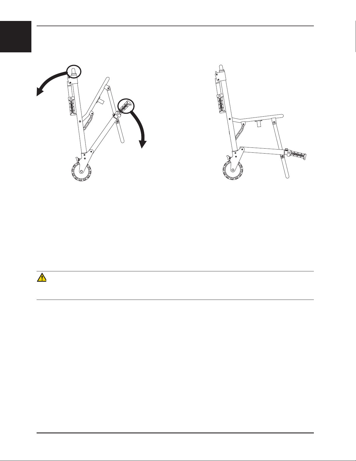
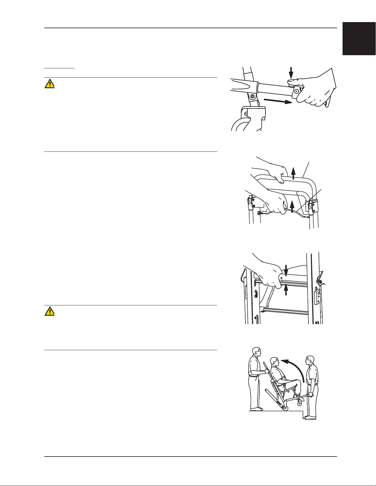
UNFOLDING THE CHAIR
Figure 1a - Unfolding the Chair
(6250 Shown)
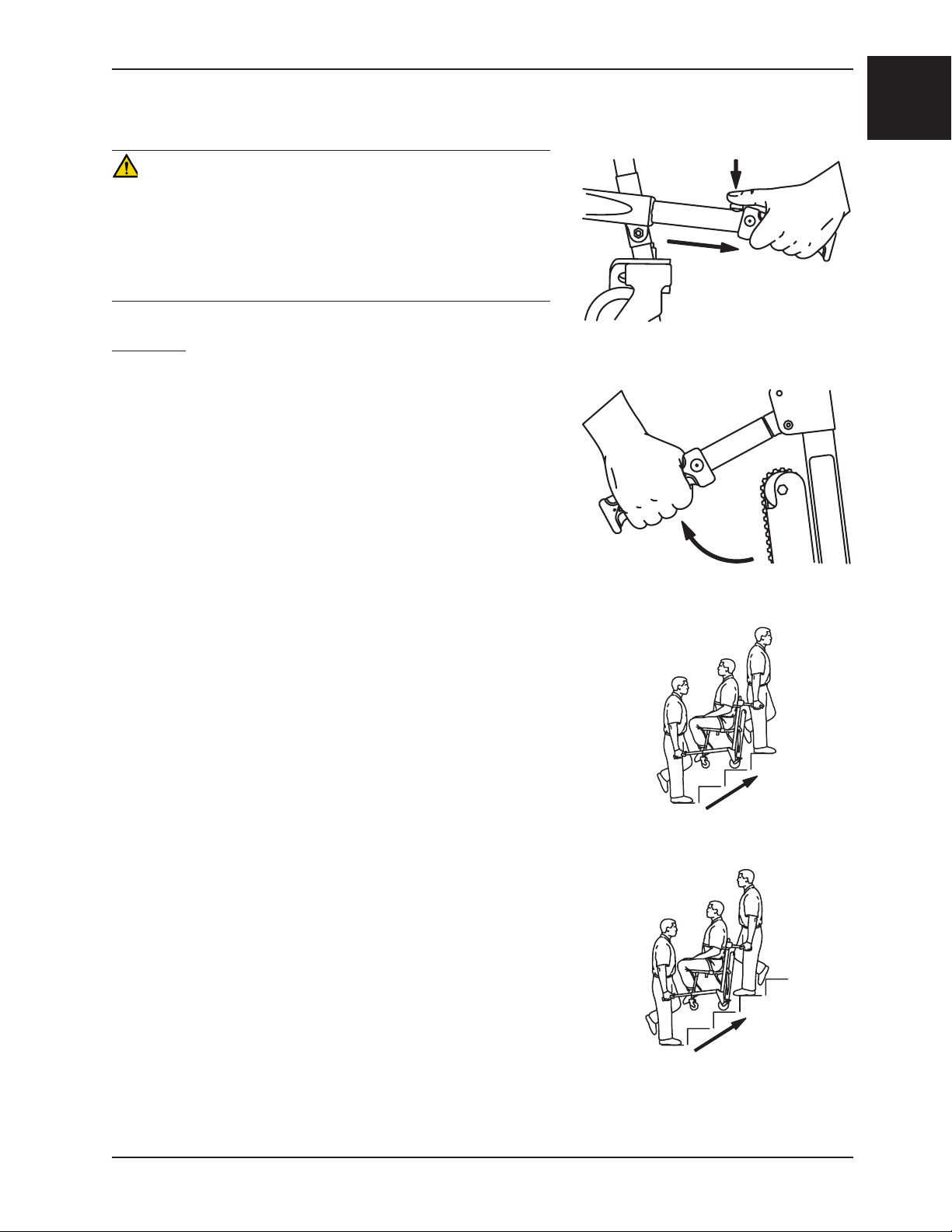
To unfold the chair (refer to Figure 1a above):
1. Stand behind the chair.
2. Apply the wheel locks (if desired).
3. Pull the backrest and the extension handle apart. The lock mechanism will automatically engage when the chair
is completely unfolded.
4. Verify the lock is engaged by pulling up on the seat. If the lock is properly engaged, the chair will not fold.
WARNING
An unlocked chair can fold during use, causing injury to the patient or operator. Always make sure the chair is locked
in the unfolded position before use.
Return To Table of Contents
1-12 6250- 001-161 REV D www.stryker.com
Page 15
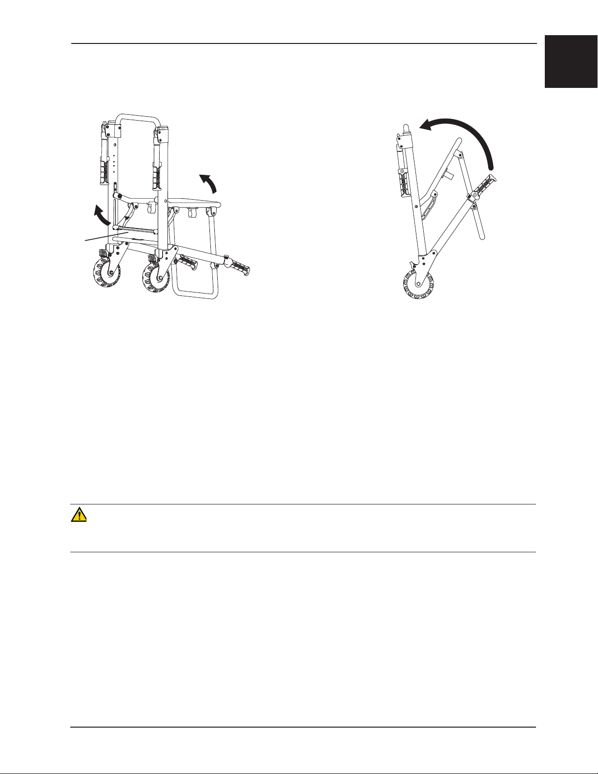
FOLDING THE CHAIR
Operation Guide
English
Figure 1b - Folding the Chair
(6250 Shown)
To fold the chair (refer to Figure 1b above):
1. Apply the wheel locks (if desired). Buckle the restraint straps and fold them neatly to prevent them from interfering
with proper folding of the chair. If the chair is equipped with the optional head support strap, secure it behind the
chair frame.
2. Stand at the side of the chair.
3. Pull up on the red lock bar at the rear of the chair.
4. Tip the chair forward.
5. Fold the seat up to the backrest until the front legs lock in the clips on the bottom of the seat tube.
Note: On models 6251 and 6252, rotate the front casters so they do not interfere with folding the chair.
WARNING
An unlocked chair can fold during use, causing injury to the patient or operator. Always make sure the chair is locked
in the unfolded position before use.
Return To Table of Contents
www.stryker.com 6250 -001-161 REV D 1-13
Page 16
English
Operation Guide
TRANSFERRING THE PATIENT TO THE STAIR-PRO® STAIR CHAIR
To transfer the patient to the chair:
1. Place the chair beside the patient.
2. Apply the wheel locks to prevent the chair from moving.
3. Open the restraint straps.
4. Transfer the patient to the chair using accepted EMS procedures.
5. Use all the restraints to secure the patient on the chair (page 1-15).
6. Disengage the wheel locks before transporting.
WARNING
The Stair-PRO® is not recommended for use with suspected cervical, spinal, or fracture injuries.
Return To Table of Contents
1-14 6250 -001-161 REV D www.stryker.com
Page 17
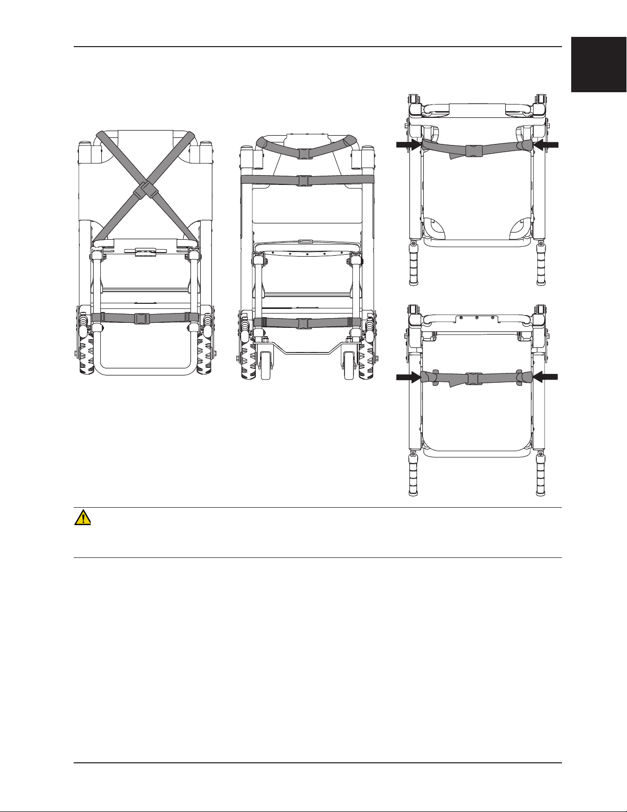
USING RESTRAINT STRAPS
Operation Guide
English
Vinyl Seat
Top View
Figure 2
Cross-Chest Configuration
Figure 3
Chest and Lap Strap
Configuration
ABS Seat
Top View
Figure 4
Lap Strap
Attachment Points
WARNING
Always use all restraint straps to secure the patient on the chair. An unrestrained patient may fall from the chair and be
injured.
The restraints can be used in two configurations.
For the cross-chest configuration (Figure 2): Buckle the chest restraints in an “X” pattern across the patient’s chest.
For the chest and lap configuration (Figure 3): Buckle one restraint across the patient’s chest and the other across
the patient’s lap.
For either configuration: Match up the color coded restraints and buckle the ankle restraint across the patient’s legs.
To avoid damage to the buckles and straps, keep the restraint straps buckled when the chair is not being used with a
patient.
When attaching the restraint straps to the chair, remember the attachment points must provide strong anchorage and
proper restraint position while not interfering with equipment and accessories.
Return To Table of Contents
www.stryker.com 6250 -001-161 REV D 1-15
Page 18
English
Operation Guide
USING RESTRAINT STRAPS - CONTINUED
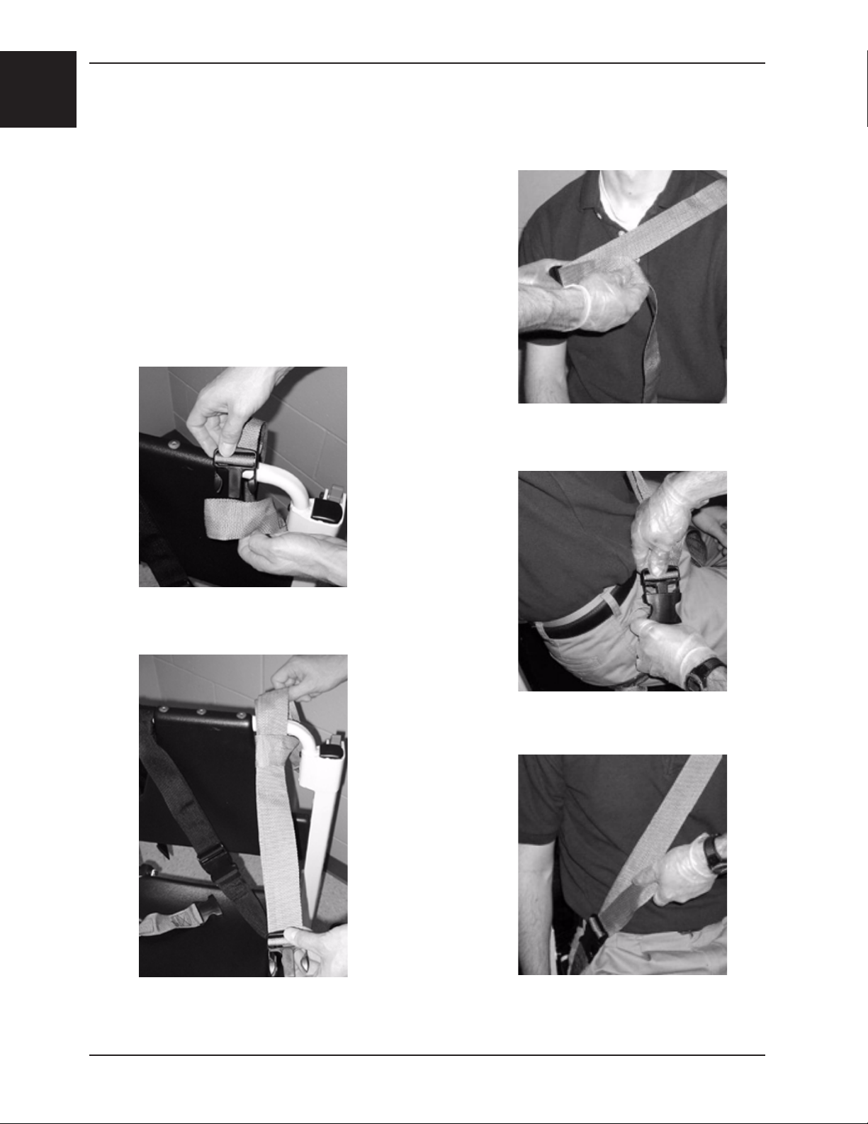
To attach the chest straps in the cross-chest configuration:
1. Wrap each strap around the chair frame, insert the end through
the loop on the end of the strap and pull it tight.
2. Pull the strap across the patient’s chest, lengthening the strap
as necessary.
3. Buckle the strap.
4. Pull the loose end of the strap to tighten it securely around
the patient.
5. Repeat for the second strap and the lap belt.
Figure 7 - Lengthen strap as
necessary
Figure 5 - Insert the end through
the loop
Figure 6 - Pull the strap tight
Figure 8 - Buckle strap
Figure 9 - Tighten strap securely
Return To Table of Contents
1-16 6250 -001-161 REV D ww w.stryker.com
Page 19
Operation Guide
USING RESTRAINT STRAPS - CONTINUED
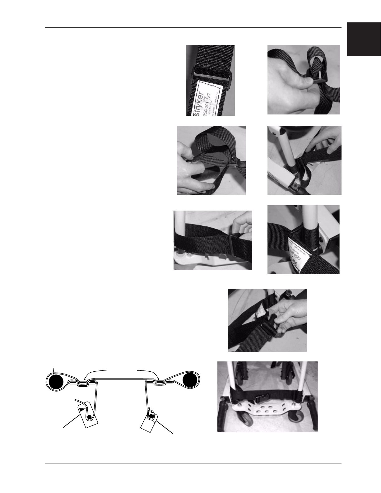
To attach the ankle strap:
1. Remove the three plastic pieces from the
strap.
2. Thread the strap through one of the
plastic “D” rings and slide the ring down to
the end of the strap up to the white label.
3. Loop the strap around the front leg of
the chair and pull the loose end of the
strap through the ring. Pull until the
ring rests against the foot rest tube.
English
4. Thread the strap through the other “D”
ring.
5. Loop the strap around the other front leg
of the chair and pull the loose end of
the strap through the loop. Pull until the
“D” ring rests against the foot rest tube.
6. Attach the final “male” end clip on the
strap.
Figure 10-18 - Attaching the leg strap
Return To Table of Contents
www.stryker.com 6250 -001-161 REV D 1-17
Page 20

English
Operation Guide
USING RESTRAINT STRAPS - CONTINUED
• To lengthen the restraint, grasp the buckle, turn it at an angle to the webbing and pull it out. A hemmed tab at the
end of the webbing prevents the buckle from coming off the strap. To shorten the restraint, grasp the hemmed tab
and pull the webbing back through the buckle until the required tightness is achieved.
• When the chair is put into service, open the restraints and place them at either side of the chair until the patient
is positioned on the seat. Lengthen the restraint, buckle it around the patient and shorten it until the required
tightness to properly secure the patient is achieved.
• To open the restraint, press the tabs on the side of the buckle to release the buckle and pull the tang out of the
receiver. To close the restraint, push the tang into the receiver until a ”click” is heard.
• Whenever a restraint is buckled on a patient, the attendant should verify the tang is locked and the extra webbing
is not tangled in the chair or hanging loose.
• Inspection of the restraints should be done at least once a month (more frequently if used heavily). Inspection
should include checking for a bent or broken receiver or tang, torn or frayed webbing, etc. Any restraint showing
wear or not operating properly must be replaced immediately.
PROPER LIFTING TECHNIQUES
When lifting the Stair-PRO® Stair Chair and patient, remember these five basic guidelines:
• Keep your hands close to your body.
• Keep your back straight.
• Coordinate your movements with your partner and lift with your legs.
• Avoid twisting.
• Always operate the Stair-PRO® Stair Chair as described in this manual.
Return To Table of Contents
1-18 6250 -001-161 REV D ww w.stryker.com
Page 21
Operation Guide
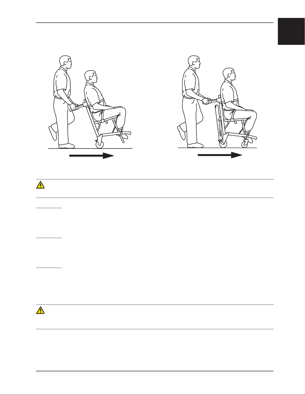
TRANSPORTING THE PATIENT ON FLAT SURFACES
English
Figure 19 - Transporting the Patient on a Model 6250
Figure 20 - Transporting the Patient on a Model 6252
CAUTION
Casters are not suitable for all surfaces. Caution should be used at all times.
Model 6250
To roll the Model 6250 Stair-PRO® over flat surfaces, use either the locking rear lift handles (if equipped), or the
backrest tube to tip the chair back. Once the chair is tipped back, use either the head end lift handles or the backrest
tube to roll and guide the chair. Lift the chair over and around obstructions with the head end and foot end lift handles.
Model 6251
To roll the Model 6251 Stair-PRO® over flat surfaces, push and guide the chair from the rear of the patient, using either
the head end lift handles or the backrest tube. Lift the chair over and around obstructions with the head end and foot
end lift handles.
Model 6252
To roll the Model 6252 Stair-PRO® over flat surfaces, follow the same method as above for the Model 6251. In addition
to the head end lift handles, the extendable upper control handle can be used in any position to roll and guide the chair.
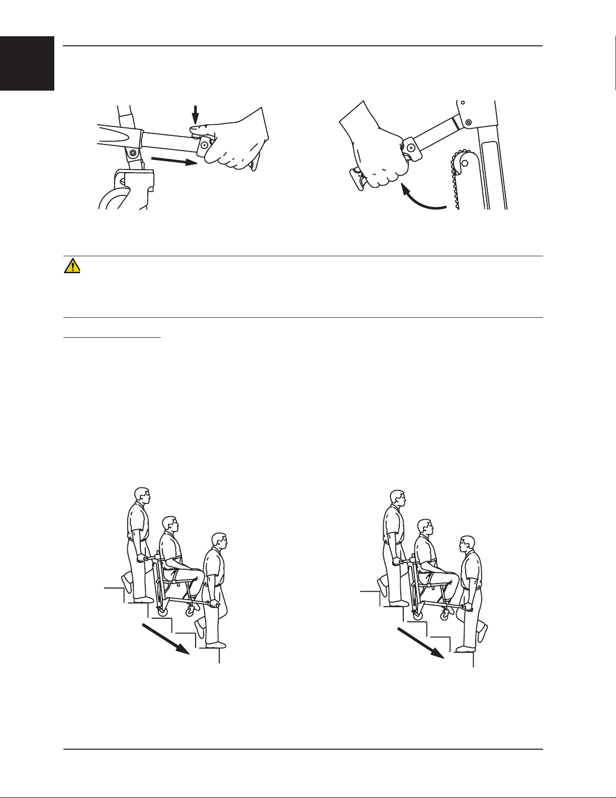
Extend the upper control handle by pulling the red release cable with one hand, and pulling up on the control handle
with the other. Release the cable to lock the handle in either the intermediate or fully extended position. Lift the chair
over and around obstructions with the head end and foot end lift handles.
WARNING
Do not push the Model 6252 with the upper control handle in the fully extended position. Pushing the chair with the
handle in the fully extended position may cause the chair to tip when obstacles are encountered.
Return To Table of Contents
www.stryker.com 6250 -001-161 REV D 1-19
Page 22
English
Operation Guide
TRANSPORTING THE PATIENT DOWN STAIRS
Figure 21 - Foot end lift handles
Figure 22 - Head end lift handles
WARNING
To avoid injury, transporting the patient on stairs requires a minimum of two operators. If more people are required to
safely control the chair, use the chart on page 1-28 as reference for proper positioning of the helpers. To avoid injury,
always verify the lift handles are locked in place before using them to lift the chair.
Models 6250 and 6251
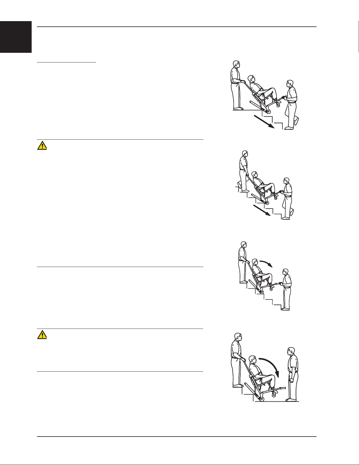
1. Foot end operator - descend in front of the Stair-PRO® Stair Chair.
2. Head end operator - approach the stairs squarely.
3. Foot end operator - push each red foot end lift handle button and pull out each handle until it stops. Release the
button and verify the handle is locked securely in position.
4. Head end operator - unfold the head end lift handles and face down the stairs.
5. Foot end operator - either face backward for improved patient monitoring or forward for an improved view of the
stairs and easier maneuvering around obstacles.
Note: Although the front operator can face either direction while lifting and carrying,
any applicable protocols for carrying chairs should be followed.
Figure 23 and 24 - Transporting down stairs
6. Both operators - simultaneously lift the chair, using the head and foot end lift handles and following the
proper lifting techniques (see page 1-18). Carry the chair slowly down the stairs, avoiding any obstructions.
Return To Table of Contents
1-20 6250- 001-161 REV D www.stryker.com
Page 23
Operation Guide
TRANSPORTING THE PATIENT DOWN STAIRS - CONTINUED
Model 6252
WARNING
• To avoid injury, always verify the Stair-TREAD™ system on the
Model 6252 is locked in place before transporting the patient.
• To avoid injury, transporting the patient on stairs requires a
minimum of two operators. If more people are required to safely
control the chair, use the chart on page 1-28 as reference for
proper positioning of the helpers.
• To avoid injury, always verify the lift handles are locked in place
before using them to lift the chair.
1. Roll the chair to the stairs and align it squarely with the edge of
the first step.
2. Foot end operator - Extend the foot end lift handles by pushing
the red release buttons and pulling the handles out until they stop.
Release the buttons and verify the handles are locked.
3. Head end operator - Use one hand to pull the red upper control
handle release cable while using the other hand to pull up and
fully extend the handle. Release the cable and verify the handle
is locked on both sides in the fully extended position.
4. Head end operator - Squeeze the red track release bar against
the black cross tube. Relax your grip on the release bar and
forcefully pull the Stair-TREAD™ system to the fully extended
position until both sides lock securely. Always verify both sides of
the Stair-TREAD™ system are locked by trying to fold it back up.
CAUTION
Release the red track release bar before clicking the Stair-TREAD™
system into the locked position. Failure to follow this procedure could
result in the track failing to lock. Always verify the Stair-TREAD™
system is locked by trying to fold it before descending stairs.
English
Figure 25 - Foot end lift handles
Figure 26 - Upper control handle release cable
Figure 27 - Red track release bar
5. Operators face each other while descending the stairs.
6. Head end operator - Tilt the chair back just far enough to allow
the Stair-TREAD™ system to contact the floor.
Figure 28 - Tilt the chair
Return To Table of Contents
www.stryker.com 6250 -001-161 REV D 1-21
Page 24
English
Operation Guide
TRANSPORTING THE PATIENT DOWN STAIRS - CONTINUED
Model 6252 - Continued
7. Both operators - Maintaining the angle, guide the Stair-PRO® Stair
Chair over the edge of the stairs, allowing the Stair-TREAD™
system to engage the first step.
8. Both operators - Glide down the stairs until the treads are level
across the edges of two or three steps.
9. Head end operator - Apply slight downward pressure on the
extendable upper control handle while the foot end operator
applies slight upward pressure on the foot end lift handles to
keep the chair from rocking forward as it glides down the stairs.
WARNING
• The Stair-TREAD™ system may not work the same on all
stair surfaces and in all environmental conditions. Based on
conditions, varying amounts of resistance may be encountered.
Avoid getting dirt or other obstructions inside the tracks. Water, ice
and/or debris on the stairs can affect operator footing and proper
operation of the Stair-TREAD™ system. To avoid injury, clear the
path or consider an alternate route. Condensation, water, ice and/
or debris on the Stair-TREAD™ system can cause unpredictable
performance, resulting in a sudden change in the weight the
operators must support.
• To avoid injury, and to aid proper operation of the Stair-TREAD™
system, ensure the belts are clean and dry before transporting
the patient.
• To avoid injury to the operators and/or the patient, operators should
never attempt to transport patient loads greater than what they can
safely lift.
Figure 29 - Track engaging first step
Figure 30 - Transporting down the stairs
10. Foot end operator - when the track reaches the last step, release
the front handles. Head end operator - allow the chair to tip
forward until all four wheels are on the ground. Roll the chair as
described on page 1-19.
11. To fold the Stair-TREAD™ system, pull the red track release bar
toward the black cross bar and fold the track up toward the chair.
Verify the Stair-TREAD™ system is locked in place.
Figure 31 - “Resting position”
CAUTION
Release the red track release bar before clicking the Stair-TREAD™
system into the locked position. Failure to follow this procedure could
result in the track failing to lock. Always verify the Stair-TREAD™
system is locked by trying to fold it before descending stairs.
If, while descending the stairs, either operator needs to pause or rest,
tilt the chair forward just enough to allow the rear wheels to rest in
the crook of the stair. To continue down the stairs from the resting
position, the head end operator exerts slight downward pressure on
the upper control handle while the foot end operator provides slight
upward pressure to tilt the chair back and engage the Stair-TREAD™
system.
Return To Table of Contents
1-22 6250- 001-161 REV D www.stryker.com
Figure 32 - Bottom of stairs
Page 25
Operation Guide
TRANSPORTING THE PATIENT UP STAIRS
WARNING
• To avoid injury, transporting the patient on stairs requires a
minimum of two operators. If more people are required to safely
control the chair, use the chart on page 1-28 as reference for
proper positioning of the helpers.
• To avoid injury, always verify the lift handles are locked in place
before using them to lift the chair.
English
All Models
1. Roll the chair to the bottom of the stairs with the patient’s back
to the stairs.
2. Foot end operator - extend the foot end lift handles by pushing the
red buttons and pulling the handles until they stop. Release the
button and verify the handle is locked.
3. Head end operator - unfold the head end lift handles.
4. The foot end operator faces up the stairs. The head end operator
may either face backward for improved patient monitoring or
forward for an improved view of the stairs and easier maneuvering
around obstacles.
Note: Although the head end operator can face either direction
while carrying, any applicable protocols for carrying chairs should
be followed.
5. Both operators - simultaneously lift the chair, using the head
and foot end lift handles and following proper lifting techniques
(see page 1-18). Carry the chair slowly up the stairs, avoiding any
obstructions.
Figure 33 - Foot end lift handles
Figure 34 - Head end lift handles
Figure 35 - Transporting up the stairs
Figure 36 - Transporting up the stairs
Return To Table of Contents
www.stryker.com 6250 -001-161 REV D 1-23
Page 26
English
Operation Guide
OPERATING THE WHEEL LOCKS
A
A
Figure 37 - Wheel Locks
(6250 Shown)
To activate the wheel locks:
1. Press down on the pedals (A) until they stop.
2. To release the wheel locks, depress the upper face of the pedal with your foot or lift up with your toe under the
pedal. The upper portion of the pedal will rest against the chair frame when the wheel lock is released.
WARNING
• Only use wheel locks during patient transfer or without a patient on the chair. Tipping could occur if the chair is
moved while the wheel locks are applied, resulting in injury to the patient or operator and/or damage to the chair.
• Wheel locks are only intended to help prevent the empty chair from rolling while unattended, and to aid in patient
transfer. A wheel lock may not provide sufficient resistance on all surfaces or under loads.
• Never leave a patient unattended on the chair or injury could result. Hold the chair securely while a patient is on
the chair.
• Never use a wheel lock on a chair with excessively worn wheels. Using a wheel lock on a wheel with less than a
5” diameter (Model 6252) or a 6” diameter (Models 6250/6251) could compromise the holding ability of the wheel
lock, possibly resulting in injury to the patient or operator and/or damage to the chair or other equipment.
Return To Table of Contents
1-24 6250 -0 01-161 REV D www.stryker.com
Page 27
Operation Guide
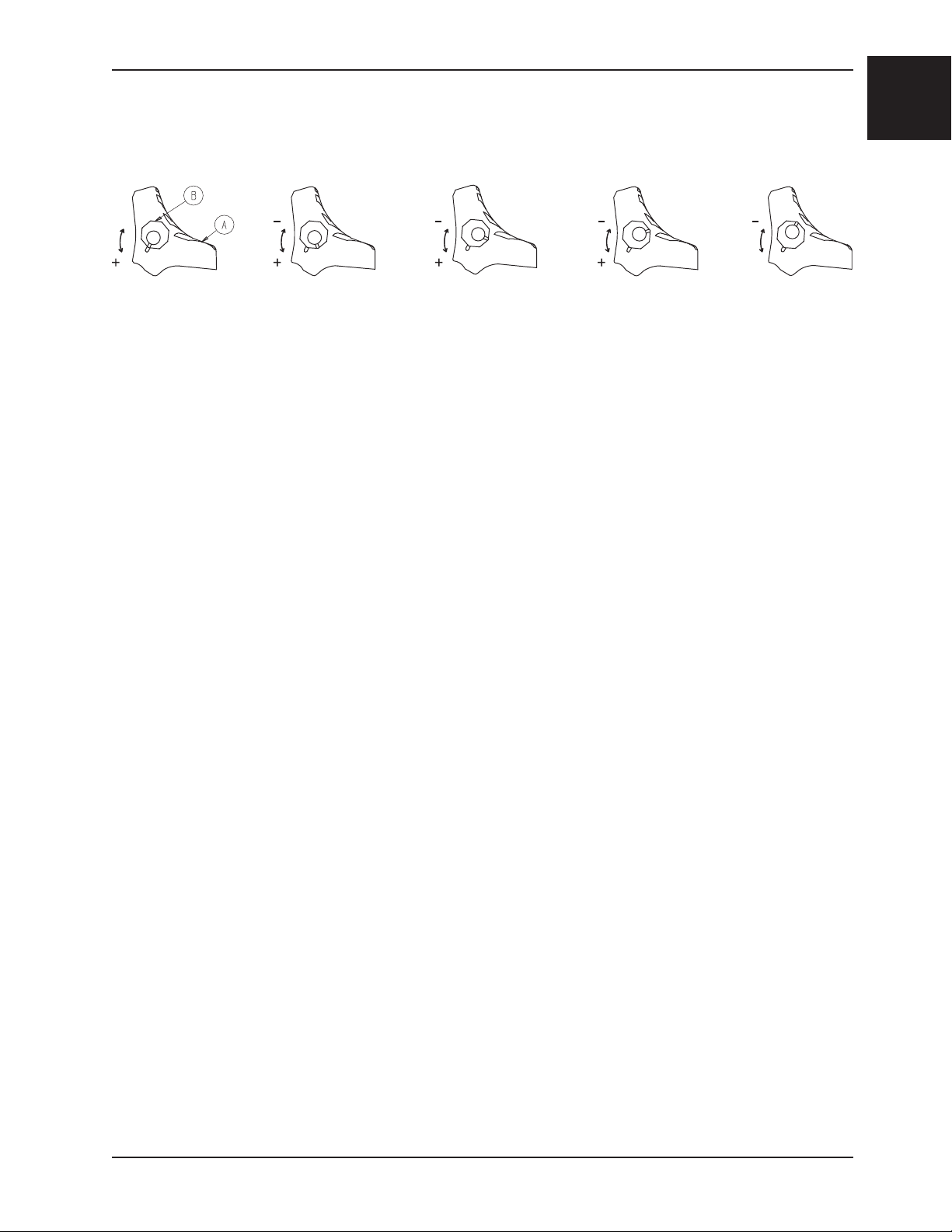
ADJUSTING THE WHEEL LOCKING FORCE
Minimum MaximumFigure 38 - Wheel locking force adjustment
To adjust the wheel locking force:
1. Remove the screw from the center of the lock pedal.
2. Remove the octagonal sleeve (B) from the pedal (A).
3. Rotate the octagonal sleeve counterclockwise to increase the pedal locking force or clockwise to decrease the
locking force.
4. Insert the octagonal sleeve (B) into the pedal (A).
5. Reinstall the screw into the center of the lock pedal.
6. Test the pedal locking force and verify that it holds properly before returning the chair to service.
English
Note: If, after adjustment, the pedal still does not hold the wheel properly, replace the wheel.
Return To Table of Contents
www.stryker.com 6250 -001-161 REV D 1-25
Page 28
English
Operation Guide
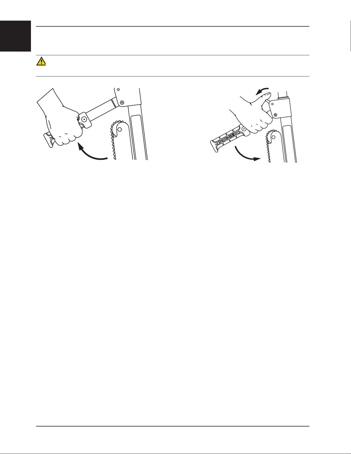
OPERATING THE OPTIONAL LOCKING REAR LIFT HANDLES
WARNING
To avoid injury, always verify the lift handles are locked in place before using them to tip the chair back.
Figure 39 - Rotate the handle up Figure 40 - Pull the trigger
To use the locking rear lift handles: Rotate the handles up until they lock into place. Verify the handles are locked
securely into place before tipping the chair back.
To lower the handles: Lift up on the handle, pull the red trigger toward you with your thumb and fold the handle down
against the chair frame.
Return To Table of Contents
1-26 6250- 001-161 REV D www.stryker.com
Page 29
Operation Guide
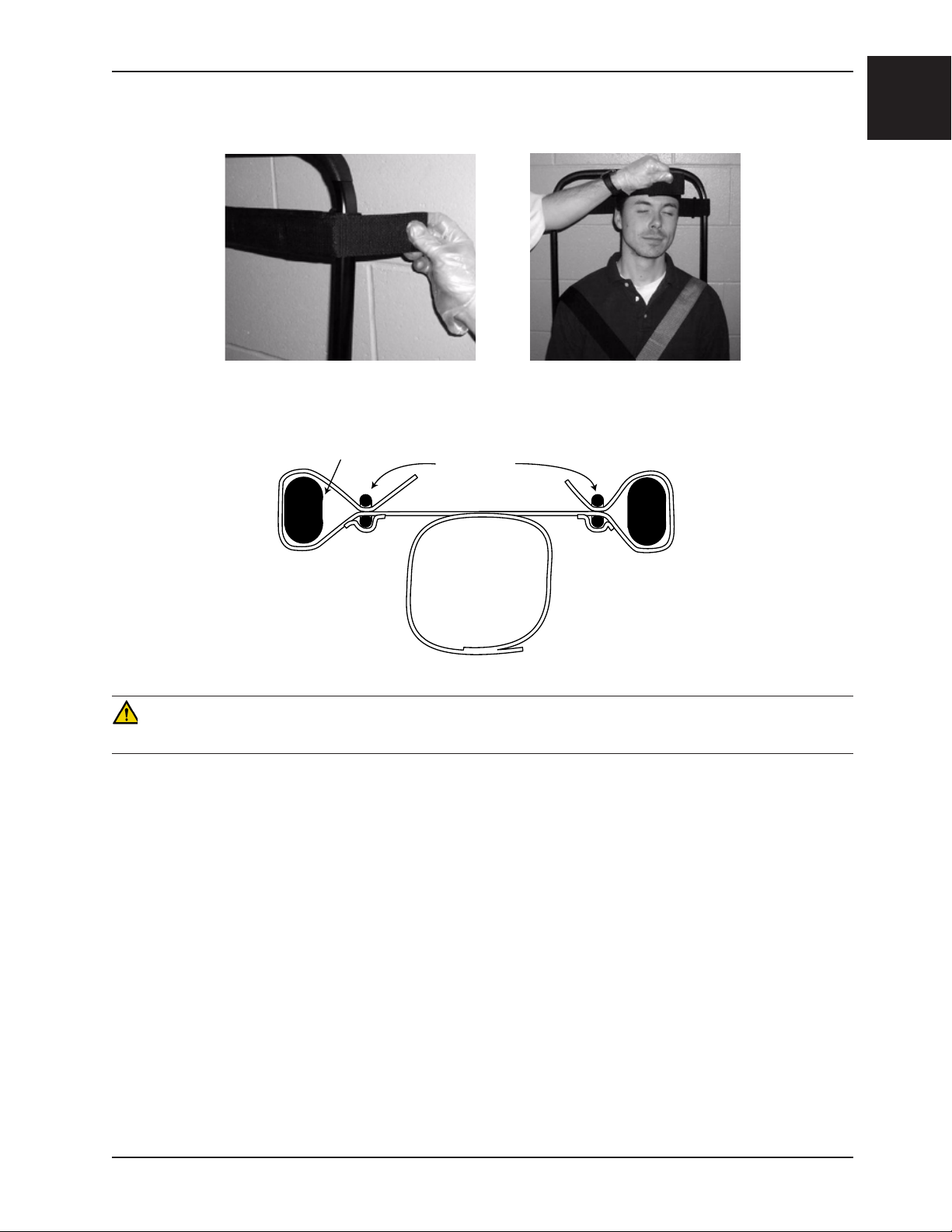
USING THE OPTIONAL HEAD SUPPORT (MODEL 6252 ONLY)
TOP VIEW
English
Upper Control Handle
Figures 41-43 - Attaching and using the head support
Slide Ring
Head Support
WARNING
The Stair-PRO® Stair Chair is not recommended for use with suspected cervical, spinal, or fracture injuries.
Before using the optional head support, the upper control handle must be extended. First, pull the red upper control
handle release cable with one hand. Then, pull up on the handle with the other hand. Release the cable and verify the
handle is securely locked into one of the two available positions.
To attach the optional head support to the extendable upper control handle:
1. Wrap the loose ends of the strap around the vertical portions of the handle, then feed them through the plastic
loops.
2. Pull tight, and secure the strap to itself.
3. Adjust the height by loosening the strap, moving it to the desired location, and tightening it again.
To support the patient’s head, position at the base of the head. For unconscious, or semiconscious patients, secure
the head using the other two parts of the strap. Wrap around the patient’s head, and overlap the straps to the desired
tightness to secure. When not in use, these straps can be wrapped back around the handle and attached to the back
of the support.
Return To Table of Contents
www.stryker.com 6250 -001-161 REV D 1-27
Page 30
English
Operation Guide
USING ADDITIONAL ASSISTANCE
WARNING
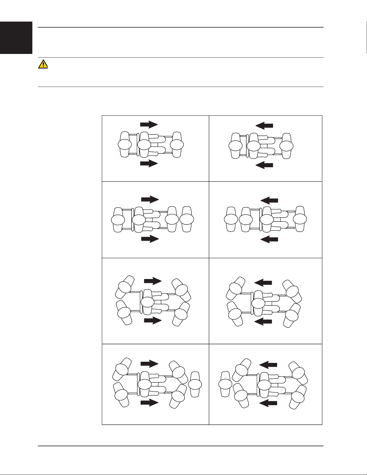
To avoid injury, transporting the patient on stairs requires a minimum of two operators. If more people are required to
safely control the chair, use the chart below as reference for proper positioning of the helpers.
DOWN STAIRS UP STAIRS
Two Operators
Two Operators
One Helper
Two Operators
Two Help ers
Operator Operator
Operator
Operator Operator
rotarepOrepleH
Helper Operator
rotarepOrepleHrepleHrotarepOrotarepO Operator
rotarepOrepleH
Helper
rotarepOrepleH
Helper
Helper
Two Operators
Three Helpers
Operator
Return To Table of Contents
1-28 6250- 001-161 REV D www.stryker.com
Helper
Operator
Helper
rotarepOrepleH
Page 31

Cleaning
The Model 6250, 6251 and 6252 Stair Chairs are designed to be power-washable. The unit may show some signs of
oxidation or discoloration from continuous washing, however, no degradation of the chair’s performance characteristics
or functionality will occur due to power washing as long as the proper procedures are followed.
WASHING PROCEDURE
• Follow the cleaning solution manufacturer’s dilution recommendations exactly.
• The preferred method Stryker Medical recommends for power washing stair chairs is with the standard hospital
surgical cart washer or hand held wand unit.
WASHING LIMITATIONS
WARNING
Use any appropriate personal safety equipment (goggles, respirator, etc.) to avoid the risk of inhaling contagion. Use
of power washing equipment can aerate contamination collected during the use of the chair.
• DO NOT STEAM CLEAN OR ULTRASONICALLY CLEAN THE UNIT.
• Maximum water temperature should not exceed 1800F/820C. Maximum air dry temperature (cart washers) is
2400F/1150C.
• Maximum water pressure should not exceed 1500 psi/130.5 bar. If a hand held wand is being used to wash the unit,
the pressure nozzle must be kept a minimum of 24 inches/61 centimeters from the unit. Failure to comply with these
instructions may invalidate any and or all warranties.
English
If a foreign material gets between the Stair-TREAD™ system belt and track frame on the Model 6252, the track frame
must be cleaned.
1. Loosen the track belts and remove the rear wheels (see page 1-36 for instructions).
2. Clean the track frame completely with rubbing alcohol.
3. Use water at high pressure (see above) to rinse the belts. Be sure to clean both the inside and outside belt
surfaces.
4. Allow the belts to completely dry before reassembly.
5. Reassemble the track belts and the rear wheels (see page 1-36 for instructions).
6. Following the appropriate cautions and warnings, test the performance of the chair using a simulated patient
weight while descending a flight of stairs.
7. If performance does not return to the original condition, the belts may need to be reconditioned or replaced.
Return To Table of Contents
www.stryker.com 6250 -001-161 REV D 1-29
Page 32

English
Cleaning
In general, when used in those concentrations recommended by the manufacturer, either phenolic type or quaternary
(excluding Virex® TB) type disinfectants can be used. Iodophor type disinfectants are not recommended for use
because staining may result.
Suggested cleaners for the 6250, 6251, and 6252 surfaces:
• Quaternary Cleaners (active ingredient - ammonium chloride)
• Phenolic Cleaners (active ingredient - o-phenylphenol)
• ChlorinatedBleachSolution(5.25%-lessthan1partbleachto100partswater)
Avoid over saturation and ensure the product does not stay wet longer than the chemical manufacturer’s guidelines
for proper disinfecting.
WARNING
• SOME CLEANING PRODUCTS ARE CORROSIVE IN NATURE AND MAY CAUSE DAMAGE TO THE PRODUCT IF
USED IMPROPERLY. If the products described above are used to clean Stryker patient care equipment, measures
must be taken to insure the chairs are wiped with a cloth soaked in clean water and thoroughly dried following
cleaning.
• Failure to properly rinse and dry the chairs will leave a corrosive residue on the surface of the chairs, possibly
causing premature corrosion of critical components.
Note: Failure to follow the above directions when using these types of cleaners may void this product’s warranty.
Return To Table of Contents
1-30 6250 -001-161 REV D www.stryker.com
Page 33

Preventative Maintenance
Operation Schedule Procedure
Cleaning and Disinfecting Each Use. See page 1-30
For 1-25 calls per month, inspect chair every 6 months
Inspection
Stair-TREAD™ system belt
reconditioning (6252)
Note: Keep up to date maintenance records using the Maintenance Record form on page 1-32.
Parts, Service or Technical Assistance
Contact Stryker Customer Service at 1-800-327-0770 or
Stryker Medical
3800 E. Centre Ave. Portage, MI 49002
ATTN: Customer Service
For 26-200 calls per month, inspect chair every 3 months
For 201+ calls per month, inspect chair monthly
After usage on approximately 500 flights of stairs or if the
Stair-TREAD™ system performance is sluggish
CHECKLIST
See below for
checklist
See page 1-39
English
_____ All fasteners secure (reference all assembly drawings)
_____ All welds intact, not cracked or broken
_____ No bent or broken tubing or sheet metal
_____ No debris in wheels
_____ All wheels secure and rolling properly
_____ Front casters secure, rolling and swiveling properly (if equipped)
_____ Wheel locks hold wheels securely when on and clear the wheels when off
_____ Chair unfolds and locks properly
_____ No rips or cracks in seat or back rest
_____ Restraint straps intact and working properly
_____ Foot end carrying handles extend and lock properly
_____ Head end carrying handles fold and unfold
_____ Upper control handle extends and locks in all positions (if equipped)
_____ Stair-TREAD™ system mechanism unfolds and locks properly (if equipped)
_____ Stair-TREAD™ system belt rolls properly (if equipped)
_____ Stair-TREAD™ system belt inner cords not showing - replace if necessary (if equipped)
_____ Stair-TREAD™ system performs as desired - recondition belts if necessary (if equipped) (see page 1-39)
_____ No lubricants present on the Stair-TREAD™ system belts or the track frame surfaces
_____ Upper release handle cable not worn or frayed - replace, if necessary (Model 6252)
_____ Optional accessories intact and operating properly
Serial Number:
Completed by: _______________________________________ Date: _________________
Return To Table of Contents
www.stryker.com 6250 -001-161 REV D 1- 31
Page 34

English
Maintenance Record
Date Maintenance Operation Performed By Hours
Return To Table of Contents
1-32 6250 -001-161 REV D www.stryker.com
Page 35

Training Record
Training Date Training Method
Trainee Name Basic
Training
Refresher
Update
English
Owner’s Manual, In-Service,
Formal Class, Etc.
Return To Table of Contents
www.stryker.com 6250 -001-161 REV D 1- 33
Page 36

English
Quick Replacement Part List
The parts and accessories listed on this page are all currently available for purchase. Some of the parts identified on
the assembly drawing parts in this manual may not be individually available for purchase. Please call Stryker Customer
Service (800)-327-0770 (Option 2), for availability and pricing.
Part Name Part Number
Back Rest, Molded ABS 6250-001-116
Belt, Track 6252-001-085
Cable, Upper Handle Release 6252-001-016
Caster, Front (6251/6252) 6251-001-083
Handle Grip 6250-001-089
Restraint, Ankle 6250-001-127
Restraint, Chest, Black 6250-001-126
Restraint, Chest, Green 6250-001-125
Restraint Set, Polypropelene 6250-160-000
Restraint Set, Vinyl 6250-001-019
Seat, Molded ABS 6250-021-000
Seat, Vinyl 6250-020-000
Touch-Up Paint (Yellow) 6060-199-010
Touch-Up Paint (Black) 6060-199-011
Wheel, Rear, 5” (6252) 6252-001-114
Wheel, Rear, 6” (6250/6251) 6060-002-010
Wheel Lock Pedal 6080-200-030
Return To Table of Contents
1-34 6250 -001-161 REV D www.stryker.com
Page 37

Service Information
VINYL SEAT REPLACEMENT
Tools Required:
• None
Figure 44 - Seat section of vinyl seat Figure 45 - Back section of vinyl seat
English
Procedure:
1. Place the seat section on the frame, wrap it around the seat tube and fit the slots in the seat section over the clips
on the underside of the seat tube. Be sure the “shiny” side of the seat is on the inside.
2. Tip the chair on its back to allow access to the bottom of the seat tube.
3. Insert both ends of the front strap through the loops in the seat section. Thread the end of the strap through the
buckle and pull it tight.
4. Thread the end of the back strap through the buckle and pull it tight.
5. Tip the chair back up on its wheels.
6. Wrap the back section around the back tube.
7. Insert both ends of the top strap through the loops in the back section. Thread the end of the strap through the
buckle and pull it tight.
8. Thread the end of the bottom strap through the buckle and pull it tight.
Return To Table of Contents
www.stryker.com 6250 -001-161 REV D 1- 35
Page 38

English
Service Information
TRACK BELT REPLACEMENT (FOR MODEL 6252)
Tools Required:
• (2) 7/16” Wrenches
• 3/16” Hex Key
• 1/2” Wrench
• 5/32” Hex Key
Procedure:
1. Using a 7/16” wrench and a 3/16” hex key, remove
the socket head cap screw, nut and washer from the
track support bracket on only one side of the chair.
Figure 46 - Remove the screw, nut and washer
2. Turn the chair upside down so it is resting on the
seat frame and back frame as shown in Figure 47.
3. Using a 1/2” wrench and a 3/16” hex key, remove the
button head cap screw, nut, spacers and wheel from the
frame on the same side as the parts removed in step one.
Figure 47 - Turn the chair upside down
Figure 48 - Remove the wheel assembly
Return To Table of Contents
1-36 6250 -001-161 REV D www.stryker.com
Page 39

Service Information
TRACK BELT REPLACEMENT (FOR MODEL 6252) - CONTINUED
4. Using a 5/32” hex key, remove the two button head cap
screws from the track spacer pivots and remove the pivots.
5. Using two 7/16” wrenches, remove the hex head cap screw, nut and
washers from both head end track rollers and remove the rollers.
6. Remove the belts by threading them through the wheel
support plate on the side where the parts were removed.
Figure 49 - Remove the track spacer pivots
English
Figure 50 - Remove the rollers
Figure 51 - Remove the worn belts
Return To Table of Contents
www.stryker.com 6250 -001-161 REV D 1- 37
Page 40

English
Service Information
TRACK BELT REPLACEMENT (FOR MODEL 6252) - CONTINUED
7. Thread the new belts through the wheel support plate.
Figure 52 - Attach the new track belt
8. Replace the track rollers, washers, hex head cap screws
and nuts.
9. Use two 7/16” wrenches to apply the desired tension to
each belt and tighten securely.
Note: To check the tension, pull up on the center of the belt
until it is taut. The gap between the belt and the track frame
should measure between 3/8” and 1” as shown in Figure 54.
10. Spin the belts to verify they roll freely.
Figure 53 - Use wrenches to apply tension to the
belts
Figure 54 - Proper belt tension
Return To Table of Contents
1-38 6250 -001-161 REV D www.stryker.com
Page 41

Service Information
TRACK BELT RECONDITIONING (FOR MODEL 6252)
Tools Required:
• 7/16” Wrenches
• Permanent Marker
• 50 Grit Sandpaper
• Sanding Block
Procedure:
1. Extend the upper control handle, open the Stair-TREAD™
system tracks and tip the chair forward until it rests on
the handle and the seat section as shown in Figure 55.
English
Figure 55 - Tip the chair forward
2. Using two 7/16” wrenches, remove the hex head bolt,
hex nut, two washers, spacer and wheel from both sides
of the track frame. Remove the wheel and spacer down
in the direction of the floor.
3. Turn both belts over so the small internal teeth are on
the outside. Put the belts on the track frame for support
while sanding them.
Note: New track belts must be installed if the inner
cords are exposed on the wear surfaces.
4. For a start/end point reference while sanding, use a
permanent marker to color a tooth on the belt.
Figure 56 - Remove the wheel spacer in the
direction of the floor
Figure 57 - Mark a belt tooth for reference
Return To Table of Contents
www.stryker.com 6250 -001-161 REV D 1- 39
Page 42

English
Service Information
TRACK BELT RECONDITIONING (FOR MODEL 6252) - CONTINUED
5. Using a sanding block with 50 Grit sandpaper,
sand both wear surfaces on the outside edges of
each belt. The purpose is to roughen the surface
of the belt just enough to remove the shiny spots
caused by normal wear. Do not over sand the belts.
WARNING
Do not sand the track teeth. Deformation of the teeth can
cause unpredictable chair performance resulting in injury to the
operators and/or patient.
Figure 58 - Sand the wear surfaces
6. Remove all sanding debris from the belts and the track
frame.
7. Turn both belts back over so the large teeth are on the
outside.
8. Replace the hex head bolt, hex nut, two washers,
spacer and wheel on both sides of the track frame.
9. Use two 7/16” wrenches to apply the desired tension to
each belt and tighten securely.
DO NOT sand
the track teeth
Figure 59 - Belt sanding surfaces
Figure 60 - Use wrenches to apply tension to the belt
Note: To check the tension, pull up on the center of the belt
until it is taut. The gap between the belt and the track frame
should measure between 3/8” and 1” as shown in Figure 61.
10. Spin the belts to verify they roll freely.
Figure 61 - Proper belt tension
Return To Table of Contents
1-4 0 6250 -001-161 REV D www.stryker.com
Page 43

Service Information
REAR WHEEL REPLACEMENT
Tools Required:
• 1/2” Wrench
• 3/16” Hex Key
Procedure:
1. Turn the chair upside down so it is resting on the
seat frame and back frame as shown in Figure 62.
English
Figure 62 - Turn the chair upside down
2. Using a 1/2” wrench and a 3/16” hex key, remove the
button head cap screw, nut, spacers and wheel from the
frame. Discard the cap screw and nut.
3. Use the new fasteners provided to attach the new wheel
to the frame.
4. Repeat for the other wheel, if necessary.
Figure 63 - Remove the wheel assembly
Return To Table of Contents
www.stryker.com 6250 -001-161 REV D 1-41
Page 44

English
Service Information
UPPER CONTROL HANDLE CABLE REPLACEMENT (FOR MODEL 6252)
Tools Required:
• 5/8” Wrench
Procedure:
1. Pull the cable and raise the extendable upper control
handle to the fully extended position.
2. Using a 5/8” wrench, remove one side of the cable.
Figure 64 - Raise the extendable handle
3. Place the washer on the end of the new cable.
4. Using a 5/8” wrench, attach one side of the new cable
to the chair frame in the hole where the old cable was
removed.
5. Repeat steps 2-4 for the other end of the cable.
Figure 65 - Remove one side of the cable
Figure 67 - Attach one side of the new cable
Figure 66 - Place the washer on the new cable
Return To Table of Contents
1-42 6250 -001-161 REV D www.stryker.com
Page 45

Table des matières
Symboles et définitions................................................................... 2-2
Symboles ......................................................................... 2-2
Définition de « Avertissement », « Mise en garde » et « Remarque » .............................. 2-2
Introduction ........................................................................... 2-3
Caractéristiques techniques ............................................................ 2-3
Identification des composants ..........................................................2-4
Garantie.............................................................................. 2-5
Réglementation de Stryker EMS relative aux renvois .......................................... 2-6
Autorisation de renvoi.................................................................2-6
Produits endommagés . . . . . . . . . . . . . . . . . . . . . . . . . . . . . . . . . . . . . . . . . . . . . . . . . . . . . . . . . . . . . . . . 2-6
Clause de garantie internationale ........................................................ 2-6
Informations sur les brevets ............................................................ 2-6
Résumé des précautions de sécurité......................................................... 2-7
Procédures d’installation..................................................................2-8
Guide d’utilisation....................................................................... 2-9
Consignes d’utilisation ...............................................................2-9
Dépliage de la chaise ................................................................2 -10
Plier la chaise ......................................................................2-11
Transfert du patient sur la chaise-civière Stair-PRO® .........................................2-12
Utilisation des sangles de retenue .......................................................2 -13
Techniques de levage correctes.........................................................2 -1 6
Transport du patient : surfaces planes ....................................................2 -17
Transport du patient : descente d’escalier..................................................2 -18
Transport du patient : montée d’escalier ...................................................2-21
Utilisation des blocages de roue.........................................................2-22
Réglage de la force de blocage des roues .................................................2-23
Utilisation des poignées de soulèvement arrière verrouillables en option ...........................2-24
Utilisation du support de tête en option (uniquement le modèle 6252) .............................2-25
Recours à des aides supplémentaires ....................................................2-26
Nettoyage.............................................................................2-27
Procédure de lavage .................................................................2-27
Limitations relatives au lavage ..........................................................2-27
Maintenance préventive ..................................................................2-29
Liste de vérification ..................................................................2-29
Rapport de maintenance................................................................. 2-30
Rapport de formation ....................................................................2-31
Liste rapide des pièces de rechange........................................................ 2-32
Informations relatives au service ........................................................... 2-33
Remplacement de siège vinyle ......................................................... 2-33
Remplacement de chenilles (pour le modèle 6252).......................................... 2-34
Reconditionnement de chenilles (pour le modèle 6252)....................................... 2-37
Remplacement de roue arrière......................................................... 2-39
Remplacement du câble de la poignée de commande supérieure
(pour le modèle 6252) ............................................................... 2-40
Français
www.stryker.com 6250 -001-161 REV D 2-1
Page 46

Français
Symboles et définitions
SYMBOLES
Avertissement/Mise en garde : Consulter la documentation d’accompagnement
Charge maximum admissible
DÉFINITION DE « AVERTISSEMENT », « MISE EN GARDE » ET « REMARQUE »
Les rubriques AVERTISSEMENT, MISE EN GARDE et REMARQUE sont particulièrement importantes et doivent faire
l’objet d’une lecture attentive.
AVERTISSEMENT
Avertit le lecteur d’une situation présentant un risque potentiel de décès ou de blessure grave. Peut également attirer
l’attention sur l’existence potentielle d’effets indésirables graves ou de risques d’accident.
MISE EN GARDE
Avertit le lecteur d’une situation potentiellement dangereuse susceptible de causer des blessures mineures ou modérées à
l’utilisateur ou au patient ou d’endommager le matériel en question ou d’autres biens. Couvre notamment les précautions
à prendre afin d’assurer l’utilisation sécuritaire et efficace du dispositif et d’éviter les dommages qui pourraient découler
de l’usage ou du mésusage du matériel.
REMARQUE
Il s’agit d’informations spécifiques destinées à faciliter l’entretien ou à clarifier des instructions importantes.
Retour à la table des matières
2-2 6250 -0 01-161 REV D www.stryker.com
Page 47

Introduction
INTRODUCTION
Ce manuel est conçu comme ouvrage de référence pour l’utilisation et l’entretien des chaises-civières Stair-PRO®
modèles 6250, 6251 et 6252. Il convient de le lire attentivement et intégralement avant de procéder à la mise en service
ou à la maintenance du produit.
CARACTÉRISTIQUES TECHNIQUES
Modèle 6250 6251 6252
Français
Charge maximum
3
500 livres 228 kg 500 livres 228 kg 500 livres 228 kg
Hauteur 36 po 91 cm 36 po 91 cm 37,5 po 95,25 cm
Largeur 20,5 po 52 cm 20,5 po 52 cm 20,5 po 52 cm
Profondeur
2
28 po 71 cm 28 po 71 cm 28 po 71 cm
Profondeur (chaise pliée) 8 po 20 cm 8 po 20 cm 8 po 20 cm
Poids 20 livres 9 kg 23 livres 10 kg 31,5 livres 14 kg
1
Dimensions mesurées depuis les bords extrêmes du châssis principal. Valeurs arrondies. Conversions calculées avant
d’arrondir.
2
Dimensions de profondeur mesurées avec les poignées extensibles repliées.
3
La capacité de charge maximum correspond au poids total réparti selon l’anatomie humaine de base. Les opérateurs doivent
tenir compte du poids du patient, de l’équipement et des accessoires pour déterminer la charge pondérale totale supportée.
Stryker se réserve le droit de modifier ces caractéristiques sans préavis.
Retour à la table des matières
www.stryker.com 6250 -001-161 REV D 2-3
Page 48

IDENTIFICATION DES COMPOSANTS
Introduction
Français
Poignées de soulèvement
Head End
du côté tête
Lift Handles
Blocage de roue
Wheel Lock
Serial
Emplacement
Number
du numéro
Location
de série
6250
Barre de verrouillage
Chair Fold
du pliage de la chaise
Lock Bar
Poignées de
soulèvement du
Lift Handles
Foot End
côté pieds
Poignées de soulèvement
Head End
du côté tête
Lift Handles
Blocage de roue
Wheel Lock
Serial
Emplacement
Number
Location
du numéro
de série
Front Caster
Roulette avant
6251
Barre de
verrouillage du
Chair Fold
pliage de la
Lock Bar
chaise
Poignées de
Foot End
Lift Handles
soulèvement du
côté pieds
Stair-TREAD™
Stair−TREAD
Barre de verrouillage de
Stair−TREAD
la Stair-TREAD™
Lock Bar
Blocage de roue
Wheel Lock
Bouton de libération de
poignée de soulèvement
Poignée de commande
Lift Handle
Release Button
Upper
supérieure
Control Handle
Roulette avant
Front Caster
6252
Manette de libération des poignées
Optional Lift Handles
de soulèvement en option
Release Lever
Câble de libération de la poignée
Upper Control Handle
de commande supérieure
Release Cable
Barre de verrouillage
Chair Fold
du pliage de la chaise
Lock Bar
Bouton de libération de
Lift Handle
poignée de soulèvement
Release Button
Poignées de
Foot End
soulèvement du
Lift Handles
côté pieds
Retour à la table des matières
2-4 6250 -0 01-161 REV D www.stryker.com
Page 49

Garantie
Stryker EMS, une division de Stryker Corporation, offre deux options de garantie distinctes aux
États-Unis :
Un (1) an – pièces et main-d’œuvre. Au titre de cette option, Stryker EMS garantit à l’acheteur initial que
ses produits seront exempts de toute non-conformité de fabrication affectant la performance du produit
et la satisfaction du client pendant une période d’un (1) an après la date de livraison. Pour tout produit
reconnu par Stryker comme défectueux à sa discrétion, l’obligation de Stryker au titre de cette garantie
se limite expressément à la fourniture de pièces de rechange et de main-d’œuvre ou à son remplacement,
à son choix.
Deux (2) ans – pièces. Au titre de cette option, Stryker EMS garantit à l’acheteur initial que les éléments
non consommables de ses produits seront exempts de toute non-conformité de fabrication affectant la
performance du produit et la satisfaction du client, pendant une période de deux (2) ans après la date
de livraison. Pour tout produit reconnu par Stryker comme défectueux à sa discrétion, l’obligation de
Stryker au titre de cette garantie se limite expressément à la fourniture de pièces de rechange ou à son
remplacement, à son choix. Les éléments consommables, c’est-à-dire les matelas, dispositifs de retenue,
supports de perfusion, filets de rangement, poches de rangement, sangles O2 et autres composants
souples, ont une garantie limitée d’un (1) an avec cette option.
Sous l’une ou l’autre option de garantie, les produits Stryker EMS sont conçus pour une durée de vie
utile prévue de 7 ans dans des conditions d’utilisation normale, et avec un entretien périodique adapté
comme décrit dans le manuel d’entretien de chaque dispositif. Stryker garantit à l’acheteur initial que les
soudures présentes sur ses produits EMS seront indemnes de défauts structurels pendant la durée de vie
utile prévue de 7 ans du produit EMS aussi longtemps que l’acheteur initial est en possession du produit.
Les acheteurs initiaux obtiendront également une garantie limitée de trois (3) ans pour les pièces des
composants du cadre en X du brancard MX-PRO R3, à condition d’avoir aussi acheté des protections
de cadre en X au moment de l’achat initial et de les avoir installées sur le MX-PRO avant sa mise en
service.
Français
À la demande de Stryker, tout produit ou pièce faisant l’objet d’une réclamation de garantie de la part d’un
acheteur initial doit être retourné en port payé à l’usine de Stryker.
Tout usage incorrect ou toute modification ou réparation effectuée par un prestataire de services non
agréé qui, selon l’avis de Stryker, a un effet matériel et indésirable sur le produit, annule la présente
garantie. Toute réparation de produits Stryker effectuée avec des pièces non fournies ou non agréées
par Stryker annule cette garantie. Aucun employé ou représentant de Stryker n’est autorisé à modifier la
présente garantie de quelque manière que ce soit.
Cette déclaration constitue l’intégralité de la garantie offerte par Stryker EMS relativement à l’équipement
susdit. HORMIS LES CLAUSES ÉNONCÉES AUX PRÉSENTES, STRYKER NE FAIT AUCUNE AUTRE
GARANTIE OU DÉCLARATION, EXPRESSE OU IMPLICITE. AUCUNE GARANTIE N’EST FAITE QUANT À
LA QUALITÉ MARCHANDE OU L’ADÉQUATION À UN USAGE PARTICULIER. EN AUCUN CAS STRYKER NE
PEUT ÊTRE TENUE RESPONSABLE, AU TITRE DES PRÉSENTES, DE TOUT DOMMAGE ACCESSOIRE
OU INDIRECT RÉSULTANT DE, OU LIÉ DE TOUTE AUTRE MANIÈRE À LA VENTE OU À L’UTILISATION
D’UN TEL ÉQUIPEMENT.
Retour à la table des matières
www.stryker.com 6250 -001-161 REV D 2-5
Page 50

Français
Garantie
RÉGLEMENTATION DE STRYKER EMS RELATIVE AUX RENVOIS
Les civières, les chaises-civières, les chaises d’évacuation, les dispositifs de fixation de civière et les
accessoires de rechange peuvent être renvoyés dans les 180 jours après leur réception s’ils satisfont aux
critères suivants :
Avant 30 jours
• Garantie de remboursement sous 30 jours en vigueur
• Tous les frais sont à la charge de Stryker EMS
• Le renvoi d’articles modifiés ne sera pas autorisé
Avant 90 jours
• Le produit doit être non utilisé, non endommagé et dans son emballage d’origine
• L’acheteurestresponsabledefraisderestockagede10%
Avant 180 jours
• Le produit doit être non utilisé, non endommagé et dans son emballage d’origine
• L’acheteurestresponsabledefraisderestockagede25%
AUTORISATION DE RENVOI
Le renvoi de produits ne peut pas être effectué sans l’accord du service clientèle de Stryker. Le numéro
d’autorisation qui sera fourni doit être inscrit sur le produit renvoyé. Stryker se réserve le droit de facturer
des frais d’expédition et de restockage pour les articles renvoyés.
LES ARTICLES SPÉCIAUX, MODIFIÉS OU N’ÉTANT PLUS SUIVIS NE PEUVENT PAS FAIRE L’OBJET
D’UN RENVOI.
PRODUITS ENDOMMAGÉS
La réglementation ICC (Interstate Commerce Commission) exige que les réclamations relatives aux
produits endommagés soient remises au transporteur dans les quinze (15) jours suivant la réception de la
marchandise. NE PAS ACCEPTER DE LIVRAISONS ENDOMMAGÉES À MOINS QUE LESDITS DOMMAGES
NE SOIENT SIGNALÉS SUR LE BORDEREAU DE LIVRAISON AU MOMENT DE LA RÉCEPTION. Dès la
réception de la notification prompte, Stryker soumettra une réclamation au transporteur approprié pour
les dommages encourus. Le montant de la réclamation sera limité au coût de remplacement réel. Si cette
information n’est pas reçue par Stryker dans les quinze (15) jours suivant la livraison du produit, ou que les
dommages ne sont pas signalés sur le bordereau de livraison au moment de la réception, le client reste
redevable du paiement intégral de la facture d’origine.
Les réclamations pour livraison incomplète doivent être déposées dans les trente (30) jours suivant la
date de la facture.
CLAUSE DE GARANTIE INTERNATIONALE
La présente garantie reflète les dispositions en vigueur aux États-Unis. Hors des États-Unis, la garantie peut
différer selon le pays. Contacter le représentant Stryker Medical local pour obtenir plus d’informations.
INFORMATIONS SUR LES BREVETS
Les produits Stryker sont couverts par un ou plusieurs des brevets suivants :
États-Unis 5,575,026 6,276,010 6,648,343 6,90 8,133 6,796,757
5,537,700 6,125,485 6,735,794 7,10 0, 2 2 4 7,398,571
D527,103
Autres brevets en instance
Retour à la table des matières
2-6 6250 -0 01-161 REV D www.stryker.com
Page 51

Résumé des précautions de sécurité
La liste qui suit récapitule les précautions de sécurité devant être observées lors de l’utilisation du matériel et de toute
intervention de maintenance ou de réparation. Ces précautions reviennent tout au long du manuel, chaque fois qu’elles sont
pertinentes. Lire attentivement cette liste avant d’utiliser le matériel ou d’effectuer toute intervention de maintenance ou de
réparation.
AVERTISSEMENT
• Ne pas modifier la chaise-civière Stair-PRO®. Toute modification de la chaise risque d’entraîner un fonctionnement
imprévisible susceptible de porter atteinte à la sécurité du patient ou de l’opérateur. Toute modification de la chaise a
également pour effet d’annuler la garantie.
• Ne pas laisser d’aides non formés aider à utiliser la chaise-civière Stair-PRO
peuvent porter atteinte à la sécurité du patient ou à la leur.
• Une chaise non verrouillée peut se replier en cours d’utilisation et causer des blessures au patient ou à l’opérateur.
Toujours s’assurer que la chaise est verrouillée en position dépliée avant de l’utiliser.
• Pour éviter toute blessure, toujours vérifier que les poignées de soulèvement sont verrouillées en place avant de les
utiliser pour soulever la chaise.
• Toujours utiliser toutes les sangles de retenue pour maintenir le patient sur la chaise. Un patient non maintenu risque
de tomber de la chaise et de se blesser.
• Ne pas pousser le modèle 6252 avec la poignée de commande supérieure en position complètement étirée. Si la chaise
est poussée avec la poignée en position complètement étirée, cela risque de faire basculer la chaise en franchissant
des obstacles.
• Ne jamais laisser un patient sur la chaise sans surveillance, sous risque de porter atteinte à sa sécurité. Tenir fermement
la chaise lorsqu’un patient se trouve sur la chaise.
• L’utilisation de la chaise-civière Stair-PRO
ou une fracture.
• Pour éviter toute blessure, le transport d’un patient dans des escaliers nécessite au moins deux opérateurs. Si d’autres
personnes sont nécessaires pour contrôler la chaise en sécurité, se référer au schéma de la page 2-26 pour le
positionnement approprié des aides.
• Utiliser les blocages de roue uniquement pendant le transfert du patient ou lorsque la chaise n’est pas occupée par un
patient. Si la chaise est déplacée alors que les blocages de roue sont activés, elle risque de se renverser et de causer
des blessures au patient ou à l’opérateur et/ou d’être endommagée.
• Ne jamais utiliser les blocages de roue de la chaise si les roues sont excessivement usées. L’utilisation du blocage de
roue d’une roue de diamètre inférieur à 12,7 cm (modèle 6252) ou 15,2 cm (modèles 6250/6251) peut en compromettre
la capacité d’immobilisation et causer des blessures au patient ou à l’opérateur et/ou endommager la chaise ou autres
équipements.
• Pour éviter toute blessure, toujours vérifier que le système Stair-TREAD™ sur le modèle 6252 est bien verrouillé en place
avant de transporter le patient.
• La présence d’eau, de glace ou de débris dans l’escalier peut gêner la prise de pied de l’opérateur et le fonctionnement
correct du système Stair-TREAD™. Pour éviter toute blessure, dégager le chemin ou envisager un autre parcours.
• La présence de condensation, d’eau, de glace et/ou de débris sur le système Stair-TREAD™ peut entraîner un
fonctionnement imprévu et une modification soudaine du poids soutenu par le ou les opérateurs. Pour éviter toute
blessure et contribuer au bon fonctionnement du système Stair-TREAD™, s’assurer que les chenilles sont propres et
sèches avant de transporter le patient.
• Ne jamais lubrifier le système Stair-TREAD™. La lubrification du système peut provoquer un fonctionnement irrégulier
risquant de causer des blessures au patient ou à l’opérateur.
• Pour éviter tout préjudice corporel aux opérateurs et/ou au patient, les opérateurs ne doivent jamais tenter de transporter
une charge supérieure à celle qu’ils peuvent soulever en sécurité.
• Utiliser l’équipement de protection individuelle adapté (lunettes, respirateur, etc.) pour éviter le risque d’inhaler des
micro-organismes contagieux. L’utilisation d’un équipement de lavage sous pression est susceptible d’aérosoliser les
contaminants collectés lors de l’utilisation de la chaise.
®
n’est pas recommandée si l’on suspecte une lésion cervicale ou rachidienne
®
. Des techniciens ou aides non formés
MISE EN GARDE
• L’utilisation incorrecte de la chaise-civière Stair-PRO® peut porter atteinte à la sécurité du patient ou de l’opérateur.
N’utiliser la chaise-civière Stair-PRO® que de la manière décrite dans ce manuel.
• Un entretien incorrect risque de causer des blessures ou d’endommager le matériel. Entretenir la chaise-civière
Stair-PRO® ainsi qu’il est décrit dans ce manuel. N’utiliser que des pièces et les procédures de maintenance
agréées par Stryker. L’utilisation de pièces et de procédures non agréées risque de causer un fonctionnement
imprévu et/ou de porter atteinte à la sécurité du patient ou de l’opérateur et annule la garantie du produit.
• Les roulettes ne conviennent pas à toutes les surfaces. Prendre en permanence les précautions nécessaires.
• Les blocages de roue ne servent qu’à aider à éviter qu’une chaise vide sans surveillance ne roule et à faciliter le
transfert du patient. Le blocage de roue peut ne pas immobiliser suffisamment les roues sur toutes les surfaces
ou en charge.
• Relâcher la barre rouge de libération des chenilles avant d’encliqueter le système Stair-TREAD™ en position
verrouillée. Ne pas respecter cette procédure risque d’empêcher le verrouillage des chenilles. Avant de descendre
un escalier, toujours essayer de replier le système Stair-TREAD™ pour vérifier qu’il est verrouillé.
Retour à la table des matières
Français
www.stryker.com 6250 -001-161 REV D 2-7
Page 52

Français
Procédures d’installation
Déballer les cartons et s’assurer que tous les articles fonctionnent correctement. Il est important que la chaise-civière
Stair-PRO® fonctionne correctement avant sa mise en service. Demander à un technicien qualifié d’utiliser la liste
suivante et le mode d’emploi pour vérifier la chaise avant sa mise en service.
• Tous les dispositifs de fixation sont bien en place (consulter l’ensemble des vues éclatées).
• Toutes les soudures sont intactes, ni fêlées ni rompues.
• Aucune tubulure ou tôle n’est tordue ou cassée.
• Pas de débris dans les roues.
• Toutes les roues sont bien fixées et roulent correctement.
• La chaise se déplie et se verrouille correctement.
• Le siège et le relève-buste ne comportent ni fissures ni déchirures.
• Les sangles de retenue du patient sont intactes et fonctionnent correctement.
• Les blocages de roue fonctionnent correctement.
• Les poignées de soulèvement du côté pieds s’étirent et se verrouillent correctement.
• Les poignées de soulèvement du côté tête se replient et se déplient.
• Les roulettes avant sont bien fixées, roulent et pivotent correctement (le cas échéant).
• La poignée de commande supérieure s’étire et se verrouille dans toutes les positions (le cas échéant).
• Le système Stair-TREAD™ se déplie et se verrouille correctement (le cas échéant).
• Les chenilles roulent correctement (le cas échéant).
• Accessoires optionnels intacts et fonctionnant correctement.
Le compartiment de stockage du véhicule dans lequel la chaise-civière Stair-PRO® sera transportée doit être
suffisamment large pour pouvoir loger la chaise pliée (consulter la page 2-3).
Au besoin, modifier le véhicule pour y installer la chaise. Ne pas modifier la chaise.
AVERTISSEMENT
Ne pas modifier la chaise-civière Stair-PRO®. Toute modification de la chaise risque d’entraîner un fonctionnement
imprévisible susceptible de porter atteinte à la sécurité du patient ou de l’opérateur. Toute modification de la chaise a
également pour effet d’annuler la garantie.
Retour à la table des matières
2-8 6250 -0 01-161 REV D www.stryker.com
Page 53

Guide d’utilisation
CONSIGNES D’UTILISATION
• N’utiliser la chaise-civière Stair-PRO® que de la manière décrite dans ce manuel.
• Lire toutes les étiquettes et instructions apposées sur la chaise avant de l’utiliser.
• Lorsqu’un patient se trouve sur la chaise, recourir à au moins deux opérateurs pour la manier dans un escalier. Si
d’autres personnes sont nécessaires pour contrôler la chaise en sécurité, se référer au schéma de la page 2-26
pour le positionnement approprié des aides.
• Ne pas rouler la chaise ou monter/descendre un escalier sans avertir le patient. Rester avec le patient et contrôler
la civière en permanence.
• Utiliser les blocages de roue uniquement pendant le transfert du patient ou lorsque la civière n’est pas occupée
par un patient.
• Toujours utiliser les sangles de retenue lorsqu’un patient se trouve sur la chaise.
• Recourir si nécessaire à des aides correctement formés pour contrôler la chaise et le patient.
AVERTISSEMENT
• Toujours utiliser toutes les sangles de retenue pour maintenir le patient sur la chaise. Un patient non maintenu
risque de tomber de la chaise et de se blesser.
• Utiliser les blocages de roue uniquement pendant le transfert du patient ou lorsque la civière n’est pas occupée
par un patient. Si la chaise est déplacée alors que les blocages de roue sont activés, elle risque de se renverser
et de causer des blessures au patient ou à l’opérateur et/ou d’être endommagée.
• La présence de condensation, d’eau, de glace et/ou de débris sur le système Stair-TREAD™ modèle 6252 peut
entraîner un fonctionnement imprévu et une modification soudaine du poids soutenu par les opérateurs. Pour éviter
toute blessure et contribuer au bon fonctionnement du système Stair-TREAD™, s’assurer que les chenilles sont
propres et sèches avant de transporter le patient.
• Pour éviter tout préjudice corporel aux opérateurs et/ou au patient, les opérateurs ne doivent jamais tenter de
transporter une charge supérieure à celle qu’ils peuvent soulever en sécurité.
Français
Retour à la table des matières
www.stryker.com 6250 -001-161 REV D 2-9
Page 54

Français
Guide d’utilisation
DÉPLIAGE DE LA CHAISE
Figure 1a - Dépliage de la chaise
(6250 illustrée)
Pour déplier la chaise (voir la Figure 1a ci-dessus) :
1. Se tenir debout derrière la chaise.
2. Activer les blocages de roue (le cas échéant).
3. Séparer le relève-buste et la poignée d’extension en tirant. Le mécanisme de verrouillage se bloque automatiquement
lorsque la chaise est complètement dépliée.
4. Tirer le siège vers le haut pour vérifier que le verrouillage est engagé. Si le verrouillage est correctement engagé,
la chaise ne se replie pas.
AVERTISSEMENT
Une chaise non verrouillée peut se replier en cours d’utilisation et causer des blessures au patient ou à l’opérateur.
Toujours s’assurer que la chaise est verrouillée en position dépliée avant de l’utiliser.
Retour à la table des matières
2-10 6250 -001-161 REV D www.stryker.com
Page 55

PLIER LA CHAISE
Guide d’utilisation
Français
Figure 1b - Plier la chaise
(6250 illustrée)
Pour plier la chaise (voir la Figure 1b ci-dessus) :
1. Activer les blocages de roue (le cas échéant). Boucler les sangles de retenue et les plier proprement pour qu’elles
ne gênent pas le pliage correct de la chaise. Si la chaise est équipée d’une sangle de support de tête optionnelle,
fixer la sangle derrière le châssis de la chaise.
2. Se tenir à côté de la chaise.
3. Tirer vers le haut la barre de verrouillage rouge à l’arrière de la chaise.
4. Basculer la chaise vers l’avant.
5. Replier le siège vers le haut en direction du relève-buste jusqu’à ce que les pieds avant s’enclenchent dans les
clips situés sous le tube du siège.
Remarque : Sur les modèles 6251 et 6252, tourner les roulettes avant pour qu’elles n’intérfèrent pas avec le pliage
de la chaise.
AVERTISSEMENT
Une chaise non verrouillée peut se replier en cours d’utilisation et causer des blessures au patient ou à l’opérateur.
Toujours s’assurer que la chaise est verrouillée en position dépliée avant de l’utiliser.
Retour à la table des matières
www.stryker.com 6250 -001-161 REV D 2-11
Page 56

Français
Guide d’utilisation
TRANSFERT DU PATIENT SUR LA CHAISE-CIVIÈRE STAIR-PRO®
Pour transférer le patient sur la chaise :
1. Placer la chaise à côté du patient.
2. Activer les blocages de roue pour immobiliser la chaise.
3. Ouvrir les sangles de retenue.
4. Transférer le patient sur la chaise en utilisant les techniques employées pour les services médicaux d’urgence
courantes.
5. Utiliser tous les dispositifs de retenue pour maintenir le patient sur la chaise (page 2-13).
6. Libérer les blocages de roue avant le transport.
AVERTISSEMENT
L’utilisation de la chaise-civière Stair-PRO® n’est pas recommandée si l’on suspecte une lésion cervicale ou rachidienne
ou une fracture.
Retour à la table des matières
2-12 6250- 001-161 REV D www.stryker.com
Page 57

Guide d’utilisation
UTILISATION DES SANGLES DE RETENUE
Français
Siège vinyle
Vue de dessus
Figure 2
Configuration croisée sur le torse
Configuration de sangles torse et
Figure 3
genoux
Siège ABS
Vue de dessus
Figure 4
Points d’attache de la
sangle des genoux
AVERTISSEMENT
Toujours utiliser toutes les sangles de retenue pour maintenir le patient sur la chaise. Un patient non maintenu risque de
tomber de la chaise et de se blesser.
Les dispositifs de retenue peuvent être utilisés dans deux configurations.
Pour la configuration croisée sur le torse (Figure 2) : boucler les sangles de retenue en « X » sur le torse du patient.
Pour la configuration torse et genoux (Figure 3) : boucler une sangle de retenue sur le torse du patient et l’autre sur
ses genoux.
Pour les deux configurations : faire correspondre les dispositifs de retenue code couleur et boucler la sangle des
chevilles sur les jambes du patient.
Pour éviter d’endommager les boucles et les sangles, garder les sangles de retenue bouclées lorsque la chaise n’est
pas utilisée pour un patient.
En fixant les sangles de retenue à la chaise, tenir compte du fait que les points d’attache doivent fournir un ancrage
résistant et permettre une position de maintien correcte, sans gêner les équipements et accessoires.
Retour à la table des matières
www.stryker.com 6250 -001-161 REV D 2 -13
Page 58

Français
Guide d’utilisation
UTILISATION DES SANGLES DE RETENUE - SUITE
Pour rattacher les sangles du torse dans la configuration
croisée sur le torse :
1. Enrouler chaque sangle autour du châssis de la chaise, insérer
l’extrémité dans l’anneau au niveau de l’extrémité de la sangle
et tirer pour serrer.
2. Tirer la sangle sur le torse du patient, en la rallongeant si
nécessaire.
3. Boucler la sangle.
4. Tirer l’extrémité libre de la sangle pour la serrer fermement
autour du patient.
5. Répéter pour la deuxième sangle et la ceinture abdominale.
Figure 7 - Rallonger la sangle selon
les besoins
Figure 5 - Insérer l’extrémité par
l’anneau
Figure 6 - Tirer la sangle pour bien
la serrer
Figure 8 - Boucler la sangle
Figure 9 - Serrer fermement la
sangle
Retour à la table des matières
2- 14 6250 -001-161 REV D www.stryker.com
Page 59

Guide d’utilisation
UTILISATION DES SANGLES DE RETENUE -
SUITE
Pour fixer la sangle des chevilles :
1. Retirer de la sangle les trois pièces en
plastique.
2. Enfiler la sangle dans l’un des anneaux en
D en plastique et glisser l’anneau jusqu’à
l’étiquette blanche à l’extrémité de la
sangle.
3. Passer la sangle autour du pied avant
de la chaise et tirer son extrémité libre
à travers l’anneau. Tirer jusqu’à ce que
l’anneau soit contre le tube du reposejambes.
4. Enfiler la sangle dans l’autre anneau en
D.
5. Passer la sangle autour de l’autre pied
avant de la chaise et tirer son extrémité
libre à travers l’anneau. Tirer jusqu’à ce
que l’anneau en D soit contre le tube du
repose-jambes.
Français
6. Fixer le clip mâle terminal sur la sangle.
Figures 10-18 - Fixation de la sangle
de jambe
Retour à la table des matières
www.stryker.com 6250 -001-161 REV D 2 -15
Page 60

Français
Guide d’utilisation
UTILISATION DES SANGLES DE RETENUE - SUITE
• Pour rallonger la sangle de retenue, tenir la boucle obliquement par rapport à la sangle et tirer. Un bourrelet cousu
à l’extrémité de la sangle empêche la boucle de se détacher de la sangle. Pour raccourcir la sangle de retenue,
saisir le bourrelet cousu et retirer la sangle à travers la boucle jusqu’au serrage correct.
• Pour mettre la chaise en service, ouvrir les sangles de retenue et les disposer de part et d’autre de la chaise
jusqu’à ce que le patient soit en place sur le siège. Rallonger la sangle, la boucler autour du patient et la raccourcir
jusqu’à ce qu’elle soit correctement serrée pour assurer le maintien correct du patient.
• Pour ouvrir la sangle, appuyer sur les languettes latérales de la boucle pour la libérer et tirer la boucle mâle
pour l’extraire de la boucle femelle. Pour fermer la sangle, pousser jusqu’au déclic la boucle mâle dans la boucle
femelle.
• Chaque fois qu’une sangle est bouclée sur un patient, l’opérateur doit vérifier que la boucle mâle est verrouillée
et que l’excès de sangle ne pend pas ou ne s’emmêle pas dans la chaise.
• Inspecter les sangles de retenue au moins une fois pas mois (plus souvent en cas d’utilisation fréquente).
L’inspection doit vérifier que les boucles mâle et femelle ne sont ni tordues ni cassées, que les sangles ne sont pas
déchirées ou effilochées, etc. Remplacer immédiatement toute sangle de retenue présentant des signes d’usure
ou ne fonctionnant pas correctement.
TECHNIQUES DE LEVAGE CORRECTES
Lors de l’élévation de la chaise-civière Stair-PRO® et du patient, se rappeler des cinq principes de base suivants :
• Garder les mains près du corps.
• Garder le dos droit.
• Coordonner les mouvements des opérateurs et soulever avec les jambes.
• Éviter toute torsion.
• Toujours utiliser la chaise-civière Stair-PRO® de la manière décrite dans ce manuel.
Retour à la table des matières
2-16 6250 -001-161 REV D ww w.stryker.com
Page 61

Guide d’utilisation
TRANSPORT DU PATIENT : SURFACES PLANES
Français
Figure 19 - Transport du patient sur un modèle 6250
Figure 20 - Transport du patient sur un modèle 6252
MISE EN GARDE
Les roulettes ne conviennent pas à toutes les surfaces. Prendre en permanence les précautions nécessaires.
Modèle 6250
Pour rouler la Stair-PRO® modèle 6250 sur des surfaces planes, utiliser soit les poignées de soulèvement arrière
verrouillables (le cas échéant), ou le tube du relève-buste pour faire basculer la chaise vers l’arrière. Une fois la
chaise basculée vers l’arrière, utiliser soit les poignées de soulèvement du côté tête de la chaise ou le tube du relèvebuste pour rouler et guider la chaise. Soulever la chaise au-dessus et autour des obstacles à l’aide des poignées de
soulèvement des côtés tête et pieds de la chaise.
Modèle 6251
Pour rouler la Stair-PRO® modèle 6251 sur des surfaces planes, pousser et guider la chaise de l’arrière du patient, au
moyen soit des poignées de soulèvement arrière du côté tête de la chaise soit du tube du relève-buste. Soulever la
chaise au-dessus et autour des obstacles à l’aide des poignées de soulèvement des côtés tête et pieds de la chaise.
Modèle 6252
Pour rouler la Stair-PRO® modèle 6252 sur des surfaces planes, employer la même méthode que celle indiquée
ci-dessus pour le modèle 6251. En plus des poignées de soulèvement du côté tête, on peut utiliser la poignée de
commande supérieure extensible dans n’importe quelle position pour rouler et guider la chaise. Pour étirer la poignée
de commande supérieure, tirer d’une main le câble de libération rouge et tirer de l’autre la poignée de commande vers
le haut. Relâcher le câble pour verrouiller la poignée en position intermédiaire ou complètement étirée. Soulever la
chaise au-dessus et autour des obstacles à l’aide des poignées de soulèvement des côtés tête et pieds de la chaise.
AVERTISSEMENT
Ne pas pousser le modèle 6252 avec la poignée de commande supérieure en position complètement étirée. Si la chaise
est poussée avec la poignée en position complètement étirée, cela risque de faire basculer la chaise en franchissant
des obstacles.
Retour à la table des matières
www.stryker.com 6250 -001-161 REV D 2 -17
Page 62

Français
Guide d’utilisation
TRANSPORT DU PATIENT : DESCENTE D’ESCALIER
Figure 21 - Poignées de soulèvement du
côté pieds
Figure 22 - Poignées de soulèvement du
côté tête
AVERTISSEMENT
Pour éviter toute blessure, le transport d’un patient dans des escaliers nécessite au moins deux opérateurs. Si d’autres
personnes sont nécessaires pour contrôler la chaise en sécurité, se référer au schéma de la page 2-26 pour le
positionnement approprié des aides. Pour éviter toute blessure, toujours vérifier que les poignées de soulèvement sont
verrouillées en place avant de les utiliser pour soulever la chaise.
Modèles 6250 et 6251
1. Opérateur du côté pieds - Descendre devant la chaise-civière Stair-PRO®.
2. Opérateur du côté tête - Approcher la chaise de l’escalier en l’alignant avec l’escalier.
3. Opérateur du côté pieds - Appuyer sur chacun des boutons rouges de poignée de soulèvement du côté pieds et
tirer chacune des poignées en butée. Libérer le bouton et s’assurer que la poignée est fermement verrouillée.
4. Opérateur du côté tête - Déplier les poignées de soulèvement du côté tête et se tourner vers le bas de l’escalier.
5. Opérateur du côté pieds - Faire face soit à la chaise pour mieux contrôler le patient, soit à l’escalier pour mieux
le voir et négocier les obstacles.
Remarque : L’opérateur du côté tête peut être tourné dans une quelconque direction en soulevant et en portant la
chaise, mais tout protocole applicable au levage de chaises doit être observé.
Figures 23 et 24 - Transport : descente d’escalier
6. Les deux opérateurs - Soulever simultanément la chaise à l’aide des poignées de soulèvement des côtés tête et
pieds de la chaise et en observant les techniques de levage correctes (voir page 2-16). Transporter lentement la
chaise pour descendre l’escalier et éviter tout obstacle.
Retour à la table des matières
2-18 6250 -001-161 REV D ww w.stryker.com
Page 63

Guide d’utilisation
TRANSPORT DU PATIENT : DESCENTE D’ESCALIER - SUITE
Modèle 6252
AVERTISSEMENT
• Pour éviter toute blessure, toujours vérifier que le système StairTREAD™ sur le modèle 6252 est bien verrouillé en place avant
de transporter le patient.
• Pour éviter toute blessure, le transport d’un patient dans des
escaliers nécessite au moins deux opérateurs. Si d’autres
personnes sont nécessaires pour contrôler la chaise en sécurité,
se référer au schéma de la page 2-26 pour le positionnement
approprié des aides.
• Pour éviter toute blessure, toujours vérifier que les poignées de
soulèvement sont verrouillées en place avant de les utiliser pour
soulever la chaise.
1. Rouler la chaise jusqu’à l’escalier et l’aligner avec le rebord de la
première marche.
2. Opérateur du côté pieds - Pousser les boutons de libération
rouges et tirer les poignées de soulèvement du côté pieds en
butée pour les étirer. Relâcher les boutons et vérifier que les
poignées sont verrouillées.
3. Opérateur du côté tête - Tirer d’une main le câble de libération
rouge de la poignée de commande supérieure et tirer de l’autre
la poignée de commande vers le haut pour l’étirer complètement.
Relâcher le câble et vérifier que la poignée est verrouillée des
deux côtés en position complètement étirée.
4. Opérateur du côté tête - Appuyer la barre rouge de libération des
chenilles contre le tube transversal noir. Relâcher la barre de
libération et tirer avec force le système Stair-TREAD™ en position
complètement étirée, jusqu’à ce que les deux côtés soient
verrouillés. Toujours essayer de replier les deux côtés du système
Stair-TREAD™ vers le haut pour vérifier qu’ils sont verrouillés.
Français
Figure 25 - Poignées de soulèvement du
côté pieds
Figure 26 - Câble de libération de la poignée
de commande supérieure
MISE EN GARDE
Relâcher la barre rouge de libération des chenilles avant d’encliqueter
le système Stair-TREAD™ en position verrouillée. Ne pas respecter
cette procédure risque d’empêcher le verrouillage des chenilles. Avant
de descendre un escalier, toujours essayer de replier le système StairTREAD™ pour vérifier qu’il est verrouillé.
5. Les opérateurs sont placés face à face en descendant l’escalier.
6. Opérateur du côté tête - Basculer la chaise en arrière suffisamment
pour permettre au système Stair-TREAD™ de toucher le sol.
www.stryker.com 6250 -001-161 REV D 2 -19
Figure 27 - Barre rouge de libération des
chenilles
Figure 28 - Basculer la chaise
Retour à la table des matières
Page 64

Guide d’utilisation
TRANSPORT DU PATIENT : DESCENTE D’ESCALIER - SUITE
Modèle 6252 - Suite
Français
7. Les deux opérateurs - En maintenant l’inclinaison, guider la chaisecivière Stair-PRO® au-dessus du rebord de la première marche de
l’escalier pour permettre au système Stair-TREAD™ de s’engager sur
la première marche.
8. Les deux opérateurs - Glisser le long de l’escalier jusqu’à ce que les
chenilles soient de niveau sur l’arête de deux ou trois marches.
9. Opérateur du côté tête - Appuyer légèrement vers le bas sur la poignée
de commande supérieure extensible pendant que l’opérateur du côté
pieds soulève légèrement les poignées de soulèvement du côté pieds
pour empêcher la chaise de basculer vers l’avant en glissant vers le
bas dans l’escalier.
AVERTISSEMENT
• Le système Stair-TREAD™ ne fonctionne pas toujours de la même
manière sur toutes les surfaces de marches et dans toutes les
conditions environnementales. Selon les conditions, on peut rencontrer
différents niveaux de résistance. Éviter de laisser pénétrer des saletés
ou autres débris dans les chenilles. La présence d’eau, de glace et/
ou de débris dans l’escalier peut gêner la prise de pied de l’opérateur
et le fonctionnement correct du système Stair-TREAD™. Pour éviter
toute blessure, dégager le chemin ou envisager un autre parcours.
La présence de condensation, d’eau, de glace et/ou de débris sur le
système Stair-TREAD™ peut entraîner un fonctionnement imprévu et
une modification soudaine du poids soutenu par le ou les opérateurs.
• Pour éviter toute blessure et contribuer au bon fonctionnement du
système Stair-TREAD™, s’assurer que les chenilles sont propres et
sèches avant de transporter le patient.
• Pour éviter tout préjudice corporel aux opérateurs et/ou au patient, les
opérateurs ne doivent jamais tenter de transporter une charge supérieure
à celle qu’ils peuvent soulever en sécurité.
Figure 29 - Les chenilles s’engagent
sur la première marche
Figure 30 - Transport : descente
d’escalier
10. Opérateur du côté pieds - Libérer les poignées avant quand les chenilles
atteignent la dernière marche. Opérateur du côté tête - Laisser la
chaise basculer vers l’avant jusqu’à ce que les quatre roues soient sur
le sol. Rouler la chaise ainsi que décrit à la page 2-17.
11. Pour replier le Stair-TREAD™, tirer la barre rouge de libération des
chenilles vers la barre transversale noire et replier les chenilles vers le
haut en direction de la chaise. Vérifier que le système Stair-TREAD™
est verrouillé en place.
Figure 31 - « Position de repos »
MISE EN GARDE
Relâcher la barre rouge de libération des chenilles avant d’encliqueter le
système Stair-TREAD™ en position verrouillée. Ne pas respecter cette
procédure risque d’empêcher le verrouillage des chenilles. Avant de
descendre un escalier, toujours essayer de replier le système Stair-TREAD™
pour vérifier qu’il est verrouillé.
Si l’un des opérateurs doit s’arrêter ou se reposer pendant la descente de
l’escalier, basculer la chaise vers l’avant juste assez pour permettre aux
roues arrière de reposer au creux de la marche. Pour reprendre la descente
de l’escalier depuis cette position de repos, l’opérateur du côté tête de la
chaise doit exercer de la poignée de commande supérieure une légère
pression vers le bas, tandis que l’opérateur du côté pieds de la chaise doit
pousser légèrement vers le haut pour basculer la chaise vers l’arrière et
engager le système Stair-TREAD™.
Retour à la table des matières
2-20 6250 -001-161 REV D ww w.stryker.com
Figure 32 - Bas de l’escalier
Page 65

Guide d’utilisation
TRANSPORT DU PATIENT : MONTÉE D’ESCALIER
AVERTISSEMENT
• Pour éviter toute blessure, le transport d’un patient dans des
escaliers nécessite au moins deux opérateurs. Si d’autres
personnes sont nécessaires pour contrôler la chaise en sécurité,
se référer aux schémas de la page 2-26 pour le positionnement
approprié des aides.
• Pour éviter toute blessure, toujours vérifier que les poignées de
soulèvement sont verrouillées en place avant de les utiliser pour
soulever la chaise.
Tous les modèles
1. Rouler la chaise jusqu’au bas de l’escalier, le patient tournant le
dos à l’escalier.
2. Opérateur du côté pieds - Appuyer sur les boutons rouges et
tirer les poignées de soulèvement du côté pieds en butée pour
les étirer. Relâcher les boutons et vérifier que les poignées sont
verrouillées.
3. Opérateur du côté tête - Déplier les poignées de soulèvement du
côté tête.
4. L’opérateur du côté pieds de la chaise doit se tourner vers le haut
de l’escalier. L’opérateur du côté tête de la chaise peut soit faire
face à la chaise pour mieux contrôler le patient, soit faire face à
l’escalier pour mieux le voir et négocier les obstacles.
Français
Figure 33 - Poignées de soulèvement du
côté pieds
Figure 34 - Poignées de soulèvement du
côté tête
Remarque : L’opérateur du côté tête peut être tourné dans une
quelconque direction en portant la chaise, mais tout protocole
applicable au levage de chaises doit être observé.
5. Les deux opérateurs - Soulever simultanément la chaise à l’aide
des poignées de soulèvement des côtés tête et pieds de la
chaise et en observant les techniques de levage correctes (voir
page 2-16). Transporter lentement la chaise pour monter l’escalier
et éviter tout obstacle.
Figure 35 - Transport : montée d’escalier
Figure 36 - Transport : montée d’escalier
Retour à la table des matières
www.stryker.com 6250 -001-161 REV D 2-21
Page 66

Français
Guide d’utilisation
UTILISATION DES BLOCAGES DE ROUE
A
A
Figure 37 - Blocages de roue
(6250 illustrée)
Pour activer les blocages de roue :
1. Appuyer à fond sur les pédales (A).
2. Pour libérer les blocages de roue, appuyer avec le pied sur la face supérieure de la pédale ou les relever du bout
du pied sous la pédale. La partie supérieure de la pédale repose contre le châssis de la chaise lorsque le blocage
de roue est libéré.
AVERTISSEMENT
• N’utiliser les blocages de roue que pendant le transfert d’un patient ou sans patient sur la chaise. Si la chaise est
déplacée alors que les blocages de roue sont activés, elle risque de se renverser et de causer des blessures au
patient ou à l’opérateur et/ou d’être endommagée.
• Les blocages de roue ne servent qu’à éviter qu’une chaise vide sans surveillance ne roule et à faciliter le transfert
du patient. Le blocage de roue peut ne pas immobiliser suffisamment les roues sur toutes les surfaces ou en
charge.
• Ne jamais laisser un patient sur la chaise sans surveillance, sous risque de porter atteinte à sa sécurité. Tenir
fermement la chaise lorsqu’un patient se trouve sur la chaise.
• Ne jamais utiliser les blocages de roue de la chaise si les roues sont excessivement usées. L’utilisation du blocage
de roue d’une roue de diamètre inférieur à 12,7 cm (modèle 6252) ou 15,2 cm (modèles 6250/6251) peut en
compromettre la capacité d’immobilisation et causer des blessures au patient ou à l’opérateur et/ou endommager
la chaise ou autres équipements.
Retour à la table des matières
2-22 6250 -001-161 REV D ww w.stryker.com
Page 67

Guide d’utilisation
RÉGLAGE DE LA FORCE DE BLOCAGE DES ROUES
Français
Minimum Maximum
Pour régler la force de blocage des roues :
1. Retirer la vis du centre de la pédale de blocage.
2. Retirer le manchon octogonal (B) de la pédale (A).
3. Tourner le manchon octogonal dans le sens anti-horaire pour augmenter la force de blocage de la pédale ou dans
le sens horaire pour la diminuer.
4. Insérer le manchon octogonal (B) dans la pédale (A).
5. Réinstaller la vis au centre de la pédale de blocage.
6. Tester la force de blocage de la pédale et vérifier qu’elle immobilise correctement la roue avant de remettre la
chaise en service.
Remarque : Si, après le réglage, la pédale ne bloque toujours pas correctement la roue, remplacer la roue.
Figure 38 - Réglage de la force de blocage des roues
Retour à la table des matières
www.stryker.com 6250 -001-161 REV D 2-23
Page 68

Guide d’utilisation
UTILISATION DES POIGNÉES DE SOULÈVEMENT ARRIÈRE VERROUILLABLES EN OPTION
AVERTISSEMENT
Français
Pour éviter toute blessure, toujours vérifier que les poignées de soulèvement sont verrouillées en place avant de les
utiliser pour basculer la chaise vers l’arrière.
Figure 39 - Tourner la poignée vers le haut Figure 40 - Tirer sur la manette
Pour utiliser les poignées de soulèvement arrière verrouillables : tourner les poignées vers le haut jusqu’à ce
qu’elles soient verrouillées en place. Vérifier que les poignées sont fermement verrouillées avant de basculer la chaise
vers l’arrière.
Pour abaisser les poignées : soulever la poignée, tirer la manette vers soi avec le pouce et plier la poignée vers le
bas contre le châssis de la chaise.
Retour à la table des matières
2-24 6250- 001-161 REV D w ww.stryker.com
Page 69

Guide d’utilisation
UTILISATION DU SUPPORT DE TÊTE EN OPTION (UNIQUEMENT LE MODÈLE 6252)
VUE DE DESSUS
Français
Poignée de commande supérieure
Figures 41-43 - Fixation et utilisation du support de tête
Anneau
coulissant
Support de tête
AVERTISSEMENT
L’utilisation de la chaise-civière Stair-PRO® n’est pas recommandée si l’on suspecte une lésion cervicale ou rachidienne
ou une fracture.
Avant d’utiliser le support de tête en option, la poignée de commande supérieure doit être étirée. D’abord, tirer d’une
main le câble rouge de libération de la poignée de commande supérieure. Tirer ensuite de l’autre main la poignée vers
le haut. Relâcher le câble et vérifier que la poignée est verrouillée dans l’une des deux positions possibles.
Pour fixer le support de tête en option à la poignée de commande supérieure extensible :
1. Enrouler les extrémités libres de la sangle autour des parties verticales de la poignée puis les passer par les
anneaux en plastique.
2. Tirer la sangle pour la serrer et la fixer sur elle-même.
3. Pour régler la hauteur, relâcher la sangle, la déplacer à l’endroit voulu, puis la resserrer.
Pour soutenir la tête du patient, placer la sangle à la base du crâne. Pour les patients inconscients ou partiellement
inconscients, fixer la tête au moyen des deux autres parties de la sangle. Enrouler les sangles autour du front du
patient ; leur chevauchement les fixe au serrage désiré. Lorsqu’elles ne sont pas utilisées, ces sangles peuvent être
enroulées vers l’arrière autour de la poignée et fixées au dos du support.
Retour à la table des matières
www.stryker.com 6250 -001-161 REV D 2-25
Page 70

Guide d’utilisation
RECOURS À DES AIDES SUPPLÉMENTAIRES
AVERTISSEMENT
Français
Pour éviter toute blessure, le transport d’un patient dans des escaliers nécessite au moins deux opérateurs. Si
d’autres personnes sont nécessaires pour contrôler la chaise en sécurité, se référer aux schémas ci-dessous pour le
positionnement approprié des aides.
DESCENTE D’ESCALIER MONTÉE D’ESCALIER
Deux opérateurs
Operator Operator
Opérateur
Opérateur
Operator Operator
Opérateur
Opérateur
Deux opérateurs
Un aide
Opérateur
Opérateur Aide
Aide Opérateur
rotarepOrepleHrepleHrotarepOrotarepO Operator
Opérateur
Deux opérateurs
Deux aides
Deux opérateurs
Trois aides
Retour à la table des matières
Aide
Operator
Opérateur
Aide
Operator
Opérateur
Opérateur
Opérateur
rotarepOrepleH
Helper Operator
Aide
rotarepOrepleH
Aide Aide
Helper
Helper
Aide
Aide
Opérateur
Helper
Aide
Operator
Opérateur
Opérateur
Helper
Aide
Opérateur
Helper
Aide
rotarepOrepleH
rotarepOrepleH
2-26 6250 -001-161 REV D ww w.stryker.com
Page 71

Nettoyage
Les chaises-civière modèles 6250, 6251 et 6252 sont lavables sous pression. Le matériel peut présenter des signes
d’oxydation ou de décoloration après des lavages sous pression répétés, sans que cela affecte les performances de
la chaise ou ses fonctionnalités si les procédures adéquates sont observées.
PROCÉDURE DE LAVAGE
• Respecter rigoureusement les recommandations de dilution du fabricant de la solution de nettoyage.
• Pour le lavage sous pression de la chaise-civière, Stryker Medical recommande d’utiliser le laveur de chariot
chirurgical standard de l’hôpital ou un jet à main.
LIMITATIONS RELATIVES AU LAVAGE
AVERTISSEMENT
Utiliser l’équipement de protection individuelle adapté (lunettes, respirateur, etc.) pour éviter le risque d’inhaler des
micro-organismes contagieux. L’utilisation d’un équipement de lavage sous pression est susceptible d’aérosoliser les
contaminants collectés lors de l’utilisation de la civière.
• NE PAS NETTOYER LA CHAISE À LA VAPEUR OU AUX ULTRASONS.
• La température maximale de l’eau ne doit pas dépasser 82 °C (180 °F). La température maximale de l’air de
séchage (systèmes de lavage de chariots) ne doit pas dépasser 115 °C (240 °F).
• La pression maximale de l’eau ne doit pas dépasser 1 500 psi (130,5 bars). Si un jet à main est utilisé pour laver la
chaise, tenir la buse sous pression à au moins 61 centimètres de la chaise. Le non-respect des directives ci-dessus
peut invalider tout ou partie de la garantie.
Français
Si des matières étrangères pénètrent entre les chenilles du système Stair-TREAD™ et le châssis des chenilles modèle
6252, il faut le nettoyer.
1. Détendre les chenilles et retirer les roues arrière (voir page 2-34 pour des instructions).
2. Nettoyer à fond à l’alcool le châssis des chenilles.
3. Rincer les chenilles à l’eau sous haute pression (voir ci-dessus). Bien nettoyer et les surfaces internes et les
surfaces externes des chenilles.
4. Permettre aux chenilles de sécher complètement avant de les remonter.
5. Remonter les chenilles et les roues arrière (voir page 2-34 pour des instructions).
6. Tester les performances de la chaise, en observant les mises en garde et les avertissements appropriés, à l’aide
d’un poids de patient simulé en descendant une volée d’escalier.
7. Si le fonctionnement normal ne reprend pas, les chenilles peuvent devoir être remises en état ou remplacées.
Retour à la table des matières
www.stryker.com 6250 -001-161 REV D 2-27
Page 72

Français
Nettoyage
En général, des désinfectants de type phénolique ou quaternaire (sauf le Virex® TB) peuvent être utilisés à condition
de respecter les concentrations recommandées par le fabricant. Les désinfectants iodés ne sont pas recommandés
car ils risquent de laisser des taches.
Nettoyants suggérés pour les surfaces des modèles 6250, 6251 et 6252 :
• Nettoyants quaternaires (ingrédient actif – chlorure d’ammonium)
• Nettoyants phénoliques (ingrédient actif – o-phénylphénol)
• Solutiond’eaudeJavel(5,25%–moinsd’unepartd’eaudeJavelpour100partsd’eau)
Pour une désinfection adéquate, éviter une concentration excessive et un contact d’une durée supérieure à celle
recommandée par le fabricant du produit chimique.
AVERTISSEMENT
• CERTAINS PRODUITS DE NETTOYAGE SONT CORROSIFS PAR NATURE ET SUSCEPTIBLES D’ENDOMMAGER
LE PRODUIT SI LES PRESCRIPTIONS D’EMPLOI NE SONT PAS RESPECTÉES. Si les produits décrits cidessus sont utilisés pour nettoyer l’équipement de soins patients Stryker, prendre les mesures appropriées pour
s’assurer que la chaise est essuyée avec un linge trempé dans de l’eau propre et complètement séchée après le
nettoyage.
• Un rinçage et un séchage incomplets laisseront à la surface de la chaise un résidu corrosif susceptible d’entraîner
la corrosion prématurée d’éléments critiques.
Remarque : Le non-respect des directives ci-dessus lors de l’utilisation de ces types de nettoyants peut annuler la
garantie du produit.
Retour à la table des matières
2-28 6250-001-161 REV D ww w.stryker.com
Page 73

Maintenance préventive
Fonctionnement Programme Procédure
Nettoyage et désinfection À chaque utilisation. Voir page 2-28
Pour 1-25 utilisations par mois, inspecter la chaise tous les
6 mois.
Inspection
Reconditionnement des
chenilles du système
Stair-TREAD™ (6252)
Remarque : Tenir à jour un rapport de maintenance à l’aide du formulaire de rapport de maintenance page 2-30.
Pièces, réparations ou service technique
Contacter le service clientèle de Stryker au +1-800-327-0770 (appel gratuit aux États-Unis) ou
Stryker Medical
3800 E. Centre Ave. Portage, MI 49002 États-Unis
ATTN : Customer Service
Pour 26-200 utilisations par mois, inspecter la chaise tous
les 3 mois.
Pour plus de 201 utilisations par mois, inspecter la chaise
chaque mois.
Après utilisation sur environ 500 volées d’escalier ou si le
fonctionnement du système Stair-TREAD™ devient lent. Voir page 2-37
Voir la liste de
vérification
ci-dessous.
Français
LISTE DE VÉRIFICATION
_____ Toutes les attaches sont solidement fixées (consulter l’ensemble des vues éclatées)
_____ Toutes les soudures sont intactes, ni fêlées ni rompues
_____ Aucune tubulure ou tôle n’est tordue ou cassée
_____ Pas de débris dans les roues
_____ Toutes les roues sont bien fixées et roulent correctement
_____ Les roulettes avant sont bien fixées, roulent et pivotent correctement (le cas échéant)
_____ Les blocages de roue immobilisent correctement les roues lorsqu’ils sont activés et les libèrent lorsqu’ils sont
désactivés
_____ La chaise se déplie et se verrouille correctement
_____ Le siège et le relève-buste ne comportent ni fissures ni déchirures
_____ Les sangles de retenue sont intactes et fonctionnent correctement
_____ Les poignées de soulèvement du côté pieds de la chaise s’étirent et se verrouillent correctement
_____ Les poignées de soulèvement du côté tête de la chaise se replient et se déplient
_____ La poignée de commande supérieure s’étire et se verrouille dans toutes les positions (le cas échéant)
_____ Le mécanisme du système Stair-TREAD™ se déplie et se verrouille correctement (le cas échéant)
_____ Les chenilles du système Stair-TREAD™ roulent correctement (le cas échéant)
_____ Le cordage interne des chenilles Stair-TREAD™ n’est pas apparent – remplacer si nécessaire (le cas échéant)
_____ Le système Stair-TREAD™ fonctionne correctement – reconditionner les chenilles si nécessaire (le cas
échéant) (voir page 2-37)
_____ Absence de lubrifiants sur les surfaces des chenilles du système Stair-TREAD™ ou du châssis des chenilles
_____ Câble de libération de la poignée de commande supérieure ni usé, ni effiloché – remplacer si nécessaire
(modèle 6252)
_____ Accessoires optionnels intacts et fonctionnant correctement
Numéro de série :
Vérification réalisée par : __________________________________ Date : _________________
Retour à la table des matières
www.stryker.com 6250 -001-161 REV D 2-29
Page 74

Français
Rapport de maintenance
Date Maintenance effectuée Par Heures
Retour à la table des matières
2-30 6250 -001-161 REV D ww w.stryker.com
Page 75

Rapport de formation
Date de formation Méthode de formation
Nom du stagiaire Formation
de base
Mise à jour
de rappel
Manuel d’utilisation, formation pratique,
cours formel, etc.
Français
Retour à la table des matières
www.stryker.com 6250 -001-161 REV D 2- 31
Page 76

Liste rapide des pièces de rechange
Tous les accessoires et les pièces indiqués sur cette page sont actuellement disponibles à la vente. Certaines des
pièces indiquées sur les vues éclatées de ce manuel peuvent ne pas être disponibles en vente individuelle. Appeler le
service clientèle Stryker au +1-800-327-0770 (option 2) (appel gratuit aux États-Unis) en ce qui concerne la disponibilité
et les prix.
Français
Dénomination de la pièce N° de pièce
Câble, libération de poignée supérieure 6252-001-016
Chenille 6252-001-085
Jeu de sangles de retenue, polypropylène 6250-160-000
Jeu de sangles de retenue, vinyle 6250-001-019
Pédale de blocage de roue 6080-200-030
Peinture pour retouche (jaune) 6060-199-010
Peinture pour retouche (noir) 6060-199-011
Prise de main 6250-001-089
Relève-buste, ABS moulé 6250-001-116
Roue, arrière, 12,7 cm (6252) 6252-001-114
Roue, arrière, 15,2 cm (6250/6251) 6060-002-010
Roulette, avant (6251/6252) 6251-001-083
Sangle de retenue, chevilles 6250-001-127
Sangle de retenue, thoracique, noire 6250-001-126
Sangle de retenue, thoracique, verte 6250-001-125
Siège, ABS moulé 6250-021-000
Siège, vinyle 6250-020-000
Retour à la table des matières
2-32 6250 -001-161 REV D ww w.stryker.com
Page 77

Informations relatives au service
REMPLACEMENT DE SIÈGE VINYLE
Outils requis :
• Aucun
Figure 44 - Section siège du siège vinyle Figure 45 - Section dossier du siège vinyle
Procédure :
1. Placer la section siège sur le châssis, l’envelopper autour du tube du siège et aligner les fentes du siège sur les
clips au-dessous du tube du siège. S’assurer que la face « brillante » du siège est dirigée vers l’intérieur.
2. Basculer le siège sur son dos pour permettre l’accès au dessous du tube du siège.
3. Introduire les deux extrémités de la sangle avant par les anneaux de la section siège. Enfiler l’extrémité de la
sangle dans la boucle et tirer pour bien serrer la sangle.
4. Enfiler l’extrémité de la sangle arrière dans la boucle et tirer pour bien serrer la sangle.
5. Basculer la chaise pour la placer de nouveau sur ses roues.
6. Envelopper la section dos autour du tube du dossier.
7. Introduire les deux extrémités de la sangle supérieure dans les anneaux du dossier. Enfiler l’extrémité de la sangle
dans la boucle et tirer pour bien serrer la sangle.
8. Enfiler l’extrémité de la sangle inférieure dans la boucle et tirer pour bien serrer la sangle.
Français
Retour à la table des matières
www.stryker.com 6250 -001-161 REV D 2-33
Page 78

Informations relatives au service
REMPLACEMENT DE CHENILLES (POUR LE MODÈLE 6252)
Outils requis :
Français
• (2) clés de 7/16 po.
• Clé hexagonale de 3/16 po.
• Clé de 1/2 po.
• Clé hexagonale de 5/32 po.
Procédure :
1. À l’aide d’une clé de 7/16 po et d’une clé hexagonale de
3/16 po, retirer la vis à tête cylindrique creuse, l’écrou et
la rondelle du support de chenilles d’un côté seulement
de la chaise.
Figure 46 - Retirer la vis, l’écrou et la rondelle
2. Retourner la chaise de façon à ce qu’elle repose sur
le châssis du siège et le châssis du dossier, comme le
montre la figure 47.
Figure 47 - Retourner la chaise
3. À l’aide d’une clé de 1/2 po et d’une clé hexagonale de
3/16 po, retirer la vis à tête bombée, l’écrou, les pièces
d’espacement et la roue du châssis du même côté que
les pièces retirés lors de la première étape.
Figure 48 - Retirer l’ensemble de roues
Retour à la table des matières
2-34 6250 -001-161 REV D ww w.stryker.com
Page 79

Informations relatives au service
REMPLACEMENT DE CHENILLES (POUR LE MODÈLE 6252) - SUITE
4. À l’aide d’une clé hexagonale de 5/32 po, retirer les deux
vis à tête bombée des pivots de la pièce d’espacement de
chenilles et retirer les pivots.
Figure 49 - Retirer les pivots de la pièce
Français
d’espacement de chenilles
5. À l’aide de deux clés de 7/16 po, retirer la vis à tête
hexagonale, l’écrou et les rondelles des deux rouleaux de
chenilles du côté tête et retirer les rouleaux.
6. Retirer les chenilles en les enfilant par la plaque-support
de roue du côté où des pièces ont été retirées.
Figure 50 - Retirer les rouleaux
Figure 51 - Retirer les chenilles usées
Retour à la table des matières
www.stryker.com 6250 -001-161 REV D 2-35
Page 80

Français
Informations relatives au service
REMPLACEMENT DE CHENILLES (POUR LE MODÈLE 6252) - SUITE
7. Enfiler les chenilles neuves par la plaque-support de
roue.
Figure 52 - Fixer les chenilles neuves
8. Remonter les rouleaux de chenilles, les rondelles, les vis
à tête hexagonale et les écrous.
9. Utiliser deux clés de 7/16 po pour tendre correctement les
chenilles et les serrer fermement.
Remarque : Pour vérifier la tension, tirer le centre de la chenille
vers le haut jusqu’à ce qu’il soit tendu. L’écartement entre la
chenille et le châssis des chenilles doit mesurer entre 1 et
2,5 cm, comme le montre la Figure 54.
10. Faire tourner les chenilles pour vérifier qu’elles roulent
librement.
Figure 53 - Tendre les chenilles avec des clés
Figure 54 - Tension de chenille appropriée
Retour à la table des matières
2-36 6250 -001-161 REV D ww w.stryker.com
Page 81

Informations relatives au service
RECONDITIONNEMENT DE CHENILLES (POUR LE MODÈLE 6252)
Outils requis :
• Clés de 7/16 po.
• Marqueur indélébile.
• Papier de verre de grain 50.
• Bloc de ponçage.
Procédure :
1. Étirer la poignée de commande supérieure, ouvrir les
chenilles du système Stair-TREAD™ et basculer la chaise
vers l’avant jusqu’à ce qu’elle repose sur la poignée et la
section siège, comme le montre la figure 55.
2. Avec deux clés de 7/16 po, retirer le boulon à tête
hexagonale, l’écrou hexagonal, les deux rondelles, la
pièce d’espacement et la roue des deux côtés du châssis
des chenilles. Retirer la roue et la pièce d’espacement
vers le bas en direction du sol.
Français
Figure 55 - Basculer la chaise vers l’avant
3. Retourner les deux chenilles afin que les petites dents
internes soient à l’extérieur. Placer les chenilles sur le
châssis des chenilles pour disposer d’un support de
ponçage.
Remarque : Des chenilles neuves doivent être montées si
le cordage interne est exposé sur les surfaces d’usure.
4. Colorer au marqueur indélébile une dent de la chenille
comme repère de début/fin du ponçage.
Figure 56 - Retirer la roue et la pièce
d’espacement vers le bas en direction du sol
Figure 57 - Marquer une dent de chenille aux
fins de référence
Retour à la table des matières
www.stryker.com 6250 -001-161 REV D 2- 37
Page 82

Informations relatives au service
RECONDITIONNEMENT DE CHENILLES (POUR LE MODÈLE 6252) - SUITE
Français
5. Avec un bloc de ponçage et du papier de verre de grain 50,
poncer les deux surfaces d’usure sur les bords externes
de chaque chenille. L’objectif est de rendre la surface de
la chenille juste assez rugueuse pour faire disparaître les
zones brillantes causées par l’usure normale. Ne pas trop
poncer les chenilles.
AVERTISSEMENT
Ne pas poncer les dents des chenilles. Toute déformation des
dents peut causer un fonctionnement imprévu de la chaise et
des blessures aux opérateurs et/ou au patient.
6. Éliminer tous les débris de ponçage des chenilles et du
châssis des chenilles.
7. Retourner les deux chenilles de manière à ce que les
grandes dents soient à l’extérieur.
8. Replacer le boulon à tête hexagonale, l’écrou hexagonal,
les deux rondelles, la pièce d’espacement et la roue des
deux côtés du châssis des chenilles.
Figure 58 - Poncer les surfaces d’usure
NE PAS poncer
les dents des
chenilles
Figure 59 - Surfaces de chenilles à poncer
9. Utiliser deux clés de 7/16 po pour tendre correctement les
chenilles et les serrer fermement.
Remarque : Pour vérifier la tension, tirer le centre de la
chenille vers le haut jusqu’à ce qu’il soit tendu. L’écartement
entre la chenille et le châssis des chenilles doit mesurer
entre 1 et 2,5 cm, comme le montre la figure 61.
10. Faire tourner les chenilles pour vérifier qu’elles roulent
librement.
Retour à la table des matières
Figure 60 - Utiliser les clés pour tendre la chenille
Figure 61 - Tension de chenille appropriée
2-38 6250 -001-161 REV D ww w.stryker.com
Page 83

Informations relatives au service
REMPLACEMENT DE ROUE ARRIÈRE
Outils requis :
• Clé de 1/2 po.
• Clé hexagonale de 3/16 po.
Procédure :
1. Retourner la chaise de façon à ce qu’elle repose sur
le châssis du siège et le châssis du dossier, comme le
montre la figure 62.
Français
Figure 62 - Retourner la chaise
2. À l’aide d’une clé de 1/2 po et d’une clé hexagonale de
3/16 po, retirer la vis à tête bombée, l’écrou, les pièces
d’espacement et la roue du châssis. Éliminer la vis à tête
bombée et l’écrou.
3. Utiliser les dispositifs de retenue neufs fournis pour fixer
la roue neuve au châssis.
4. Répéter pour l’autre roue, si nécessaire.
Figure 63 - Retirer l’ensemble de roues
Retour à la table des matières
www.stryker.com 6250 -001-161 REV D 2-39
Page 84

Informations relatives au service
REMPLACEMENT DU CÂBLE DE LA POIGNÉE DE COMMANDE SUPÉRIEURE
(POUR LE MODÈLE 6252)
Outils requis :
Français
• Clé de 5/8 po.
Procédure :
1. Tirer le câble et tirer la poignée de commande supérieure
extensible jusqu’en position complètement étirée.
2. Avec une clé de 5/8 po, retirer un côté du câble.
Figure 64 - Soulever la poignée extensible
3. Placer la rondelle sur l’extrémité du nouveau câble.
4. Avec une clé de 5/8 po, fixer un côté du nouveau câble au
châssis de la chaise, dans le trou de l’ancien câble.
5. Répéter les étapes 2 à 4 pour l’autre extrémité du câble.
Figure 66 - Placer la rondelle sur le nouveau
Retour à la table des matières
Figure 65 - Retirer un côté du câble
Figure 67 - Fixer un côté du nouveau câble
câble
2-40 6250 -001-161 REV D ww w.stryker.com
Page 85

Inhaltsverzeichnis
Symbole und Definitionen ................................................................. 3-2
Symbole .......................................................................... 3-2
Definition der Begriffe Warnung / Vorsicht / Hinweis .......................................... 3-2
Einführung . . . . . . . . . . . . . . . . . . . . . . . . . . . . . . . . . . . . . . . . . . . . . . . . . . . . . . . . . . . . . . . . . . . . . . . . . . . . 3-3
Technische Daten ................................................................... 3-3
Bestandteile des Stuhls ............................................................... 3-4
Herstellergarantie....................................................................... 3-5
Stryker-EMS-Rückgaberichtlinien ........................................................3-6
Rückgabeberechtigung................................................................3-6
Beschädigte Artikel ..................................................................3-6
Internationale Garantieklausel .......................................................... 3-6
Patentangaben .....................................................................3-6
Zusammenfassung der Sicherheitsvorkehrungen ................................................ 3-7
Einsatzvorbereitung .....................................................................3-8
Bedienungsanleitung.....................................................................3-9
Bedienungsrichtlinien ................................................................3-9
Ausklappen des Stuhls................................................................3 -10
Zusammenklappen des Stuhls ..........................................................3-11
Umlagern des Patienten auf den Stair-PRO® Treppenrollstuhl ...................................3-12
Verwendung der Haltegurte ............................................................3-13
Richtige Hebetechniken ...............................................................3 -16
Transportieren des Patienten auf ebenen Flächen............................................3-17
Transportieren des Patienten eine Treppe hinunter ...........................................3 -18
Transportieren des Patienten eine Treppe hinauf.............................................3-21
Betätigen der Radsperren .............................................................3-22
Einstellen der Sperrstärke .............................................................3-23
Bedienen der optionalen hinteren Verriegelungstragegriffe .....................................3-24
Verwenden der optionalen Kopfstütze (nur Modell 6252) .......................................3-25
Einsatz zusätzlicher Helfer .............................................................3-26
Reinigung.............................................................................3-27
Reinigungsverfahren .................................................................3-27
Beim Waschen zu beachtende Einschränkungen.............................................3-27
Vorbeugende Wartung ...................................................................3-29
Checkliste .........................................................................3-29
Wartungsnachweis ..................................................................... 3-30
Schulungsnachweis .....................................................................3-31
Kurzgefasste Ersatzteilliste ............................................................... 3-32
Serviceinformationen ................................................................... 3-33
Austausch des Vinylsitzes ............................................................ 3-33
Austausch des Schienenriemens (für Modell 6252).......................................... 3-34
Aufarbeiten der Schienenriemen (für Modell 6252) .......................................... 3-37
Austausch des Hinterrads............................................................. 3-39
Austausch des Seilzugs für den oberen Steuergriff (für Modell 6252) ............................ 3-40
Deutsch
www.stryker.com 6250 -001-161 REV D 3 -1
Page 86

Deutsch
Symbole und Definitionen
SYMBOLE
Warnung/Vorsicht: Begleitdokumentation lesen
Sichere Arbeitslast
DEFINITION DER BEGRIFFE WARNUNG / VORSICHT / HINWEIS
Die Wörter WARNUNG, VORSICHT und HINWEIS haben jeweils eigene Bedeutung und erfordern aufmerksame
Beachtung.
WARNUNG
Warnt den Leser vor einer Situation, welche bei Nichtvermeiden zu schwerer Verletzung oder zum Tod führen könnte.
Hierunter können auch mögliche schwere Nebenwirkungen oder Sicherheitsrisiken beschrieben werden.
VORSICHT
Warnt den Leser vor einer möglichen gefährlichen Situation, welche bei Nichtvermeiden zu leichten oder mittelschweren
Verletzungen des Benutzers oder des Patienten oder zu Beschädigung der Ausrüstung oder anderer Gegenstände führen
könnte. Dies beinhaltet auch die nötigen besonderen Vorsichtsmaßnahmen zur sicheren und effektiven Benutzung des
Geräts und die nötigen Vorsichtsmaßnahmen, um Beschädigungen des Geräts zu vermeiden, die als Ergebnis des
Gebrauchs oder der unsachgemäßen Benutzung auftreten könnten.
HINWEIS
Hinweise enthalten Informationen, die die Wartung erleichtern oder wichtige Anweisungen verdeutlichen.
Zurück zum Inhaltsverzeichnis
3-2 6250 -001-161 REV D www.stryker.com
Page 87

Einführung
EINFÜHRUNG
Dieses Handbuch enthält Anleitungen zur Bedienung und Wartung des Stair-PRO® Treppenrollstuhls, Modelle 6250,
6251 und 6252. Bitte gründlich durchlesen, bevor Sie das Produkt verwenden oder Wartungsmaßnahmen daran
durchführen.
TECHNISCHE DATEN
Modelle 6250 6251 6252
Maximalbelastung
3
500 Pfund 228 kg 500 Pfund 228 kg 500 Pfund 228 kg
Höhe 36 Zoll 91 cm 36 Zoll 91 cm 37, 5 Z o l l 95,25 cm
Breite 20,5 Zoll 52 cm 20,5 Zoll 52 cm 20,5 Zoll 52 cm
2
Tiefe
28 Zoll 71 cm 28 Zoll 71 cm 28 Zoll 71 cm
Zusammengeklappt: Tiefe 8 Zoll 20 cm 8 Zoll 20 cm 8 Zoll 20 cm
Gewicht 20 Pfund 9 kg 23 Pfund 10 kg 31,5 Pfund 14 kg
1
Gemessen von den Außenkanten des Hauptrahmens. Angaben gerundet. Angaben wurden erst umgerechnet und dann auf- bzw.
abgerundet.
2
Die Tiefenmaße werden bei eingezogenen ausziehbaren Griffen genommen.
3
Die maximale Tragfähigkeit entspricht dem Gesamtgewicht, das sich entsprechend der menschlichen Grundanatomie verteilt.
Zur Bestimmung des Gesamtgewichts muss das Gewicht des Patienten, der Ausrüstung und des Zubehörs berücksichtigt werden.
Stryker behält sich das Recht vor, technische Daten ohne Vorankündigung zu ändern.
Deutsch
Zurück zum Inhaltsverzeichnis
www.stryker.com 6250 -001-161 REV D 3-3
Page 88

BESTANDTEILE DES STUHLS
Einführung
Deutsch
Tragegriffe am
Head End
Kopfende
Lift Handles
Radsperre
Wheel Lock
Lage der
Serial
Seriennummer
Number
Location
6250
Chair Fold
Klappsperrstange
Lock Bar
Tragegriffe am
Foot End
Fußende
Lift Handles
Tragegriffe am
Lift Handles
Radsperre
Wheel Lock
Head End
Kopfende
Serial
Lage der
Number
Seriennummer
Location
Front Caster
Vordere
Schwenkrolle
6251
Chair Fold
Klappsperrstange
Lock Bar
Tragegriffe am
Foot End
Lift Handles
Fußende
Stair-TREAD™
Stair−TREAD
Stair-TREAD™
Stair−TREAD
Sperrstange
Lock Bar
Radsperre
Wheel Lock
Control Handle
Oberer Steuergriff
Freigabetaste für
Lift Handle
Release Button
Tragegriff
Upper
Front Caster
Schwenkrolle
Vordere
6252
Optionaler Entriegelungshebel
Optional Lift Handles
für Tragegriffe
Release Lever
Entriegelungsseilzug für
Upper Control Handle
oberen Steuergriff
Release Cable
Chair Fold
Klappsperrstange
Lock Bar
Freigabetaste für
Release Button
Tragegriffe am
Foot End
Fußende
Lift Handles
Lift Handle
Tragegriff
Zurück zum Inhaltsverzeichnis
3-4 6250 -001-161 REV D www.stryker.com
Page 89

Herstellergarantie
Stryker EMS, ein Geschäftszweig der Stryker Corporation, bietet zwei verschiedene Garantieoptionen in
den Vereinigten Staaten:
Ein (1) Jahr Garantie auf Teile und Arbeitszeit. Unter dieser Option garantiert Stryker EMS dem
ursprünglichen Käufer für eine Dauer von einem (1) Jahr nach Auslieferung, dass seine Produkte frei von
Herstellungsfehlern sind, die die Produktleistung und Kundenzufriedenheit beeinträchtigen können. Diese
Garantie von Stryker beschränkt sich ausdrücklich auf Ersatzteile und Arbeitszeit für bzw. nach eigenem
Ermessen auf den Ersatz des Produkts, das von Stryker unabhängig als defekt befunden wurde.
Zwei (2) Jahre Garantie auf Teile. Unter dieser Option garantiert Stryker EMS dem ursprünglichen Käufer
für eine Dauer von zwei (2) Jahren nach Auslieferung, dass die verschleißfreien Bestandteile seiner
Produkte frei von Herstellungsfehlern sind, die die Produktleistung und Kundenzufriedenheit beeinträchtigen
können. Diese Garantie von Stryker beschränkt sich ausdrücklich auf Ersatzteile für bzw. nach eigenem
Ermessen auf den Ersatz des Produkts, das von Stryker unabhängig als defekt befunden wurde. Auf
Verbrauchsteile, wie Matratzen, Haltegurte, Infusionsständer, Aufbewahrungsnetze, Aufbewahrungsbeutel,
O2-Gurte und andere Weichartikel, gibt es unter dieser Option eine einjährige (1-jährige) beschränkte
Garantie.
Deutsch
Bei beiden Garantieoptionen gilt, dass die Produkte von Stryker EMS auf eine erwartete Einsatzdauer
von 7 Jahren ausgelegt sind, normalen Gebrauch, normale Bedingungen und geeignete regelmäßige
Wartung wie im Wartungshandbuch für jedes Produkt beschrieben vorausgesetzt. Stryker garantiert dem
ursprünglichen Käufer, dass die Schweißnähte an seinen EMS-Produkten im Besitz des ursprünglichen
Käufers während der erwarteten Einsatzdauer des EMS-Produktes von 7 Jahren frei von strukturellen
Defekten bleiben. Ursprüngliche Käufer erhalten auch eine dreijährige (3-jährige) beschränkte Garantie
auf die X-Rahmen-Komponenten der Bahre MX-PRO R3, wenn sie zum Zeitpunkt des ursprünglichen
Kaufs ebenfalls X-Rahmen-Schützer erwerben und diese am MX-PRO vor Inbetriebnahme angebracht
haben.
Bei Inanspruchnahme der Garantie durch den ursprünglichen Käufer hat dieser das Produkt bzw. das Teil
auf Verlangen von Stryker unter Vorauszahlung der Frachtkosten ans Werk von Stryker einzusenden.
Unsachgemäße Verwendung oder Veränderung oder Reparatur durch unberechtigte Serviceanbieter, die
das Produkt nach Einschätzung von Stryker wesentlich beeinträchtigt, lässt diese Garantie erlöschen.
Reparaturen von Stryker-Produkten unter Verwendung von Teilen, die nicht von Stryker geliefert oder
genehmigt sind, führen zum Verlust der Garantieansprüche. Kein Mitarbeiter oder Vertreter von Stryker ist
berechtigt, diese Garantiebestimmungen auf irgendeine Weise zu ändern.
Diese Ausführungen umfassen die gesamten Garantieleistungen von Stryker EMS bezüglich der
vorgenannten Ausrüstung. STRYKER MACHT KEINE HIERÜBER HINAUSGEHENDEN AUSDRÜCKLICHEN
ODER STILLSCHWEIGENDEN GARANTIEZUSICHERUNGEN. ES BESTEHT KEINE GARANTIE AUF
MARKTGÄNGIGKEIT ODER EIGNUNG FÜR EINEN BESTIMMTEN ZWECK. KEINESFALLS IST STRYKER
HAFTBAR FÜR BEGLEIT- ODER FOLGESCHÄDEN ODER ANDERE SCHÄDEN DURCH DEN VERKAUF
ODER DIE VERWENDUNG DIESER PRODUKTE.
Zurück zum Inhaltsverzeichnis
www.stryker.com 6250 -001-161 REV D 3-5
Page 90

Deutsch
Herstellergarantie
STRYKER-EMS-RÜCKGABERICHTLINIEN
Tragen, Treppenrollstühle, Evakuierungsstühle, Tragenbefestigungen und Extrazubehör können bis zu
180 Tage nach Erhalt zurückgegeben werden, wenn die folgenden Bedingungen erfüllt sind:
Bis zu 30 Tagen nach Erhalt
• Es gilt eine 30-tägige Geld-zurück-Garantie
• Stryker EMS trägt alle Kosten
• Veränderte Artikel werden nicht zurückgenommen
Bis zu 90 Tagen nach Erhalt
• Das Produkt darf nicht gebraucht, und nicht beschädigt sein und muss sich in der Originalverpackung
befinden
• DerKundezahlteineRückgabegebührvon10%
Bis zu 180 Tagen nach Erhalt
• Das Produkt darf nicht gebraucht, und nicht beschädigt sein und muss sich in der Originalverpackung
befinden
• DerKundezahlteineRückgabegebührvon25%
RÜCKGABEBERECHTIGUNG
Artikel können nur nach Genehmigung durch den Stryker-Kundendienst zurückgegeben werden. Es
wird eine Warenrücksendungsautorisierungsnummer vergeben, die auf dem retournierten Artikel
vermerkt werden muss. Stryker behält sich das Recht vor, für zurückgegebene Artikel Versand- und
Reinventarisierungsgebühren zu verlangen.
SPEZIELLE, MODIFIZIERTE ODER NICHT MEHR GEFÜHRTE ARTIKEL KÖNNEN NICHT ZURÜCKGEGEBEN
WERDEN.
BESCHÄDIGTE ARTIKEL
Die Vorschriften der ICC (Interstate Commerce Commission) verlangen, dass Ansprüche wegen
beschädigter Artikel innerhalb von fünfzehn (15) Tagen nach Erhalt des Artikels beim Spediteur erhoben
werden müssen. KEINE BESCHÄDIGTE LIEFERUNG ENTGEGENNEHMEN, SOFERN DIE BESCHÄDIGUNG
NICHT ZUM ZEITPUNKT DES EMPFANGS AUF DER ZUSTELLQUITTUNG VERMERKT WURDE. Nach
umgehender Benachrichtigung fordert Stryker vom betreffenden Spediteur Schadensersatz. Der Anspruch
beschränkt sich auf die tatsächlichen Ersatzkosten. Falls Stryker diese Angaben nicht innerhalb von
fünfzehn (15) Tagen nach Zustellung des Artikels erhält oder die Beschädigung nicht beim Empfang auf
der Empfangsquittung vermerkt wurde, ist der Käufer für die vollständige Bezahlung der Originalrechnung
verantwortlich.
Ansprüche wegen fehlender Teile in der Lieferung müssen innerhalb von dreißig (30) Tagen ab
Rechnungsdatum erhoben werden.
INTERNATIONALE GARANTIEKLAUSEL
Diese Garantie beruht auf der US-amerikanischen Gesetzgebung. Garantieleistungen außerhalb der USA
können je nach Land verschieden ausfallen. Wenden Sie sich zwecks weiterer Informationen bitte an Ihre
örtliche Vertretung von Stryker Medical.
PATENTANGABEN
Stryker-Produkte sind durch eines oder mehrere der folgenden Patente geschützt:
USA 5,575,026 6,276,010 6,648,343 6,90 8,133 6,796,757
5,537,700 6,125,485 6,735,794 7,10 0, 2 2 4 7,398,571
D527,103
Weitere Patente angemeldet
Zurück zum Inhaltsverzeichnis
3-6 6250-001-161 REV D www.stryker.com
Page 91

Zusammenfassung der Sicherheitsvorkehrungen
Die folgende Liste führt Sicherheitsvorkehrungen auf, die bei Verwendung oder Wartung des Produkts befolgt werden
müssen. Die Sicherheitsvorkehrungen werden an entsprechenden Stellen im gesamten Handbuch wiederholt. Die Liste
aufmerksam durchlesen, bevor Sie das Produkt verwenden oder warten.
WARNUNG
• Den Stair-PRO® Treppenrollstuhl nicht verändern. Veränderungen am Stuhl können dessen Eigenschaften unvorhersehbar
beeinträchtigen, was zur Verletzung des Patienten oder Bedieners führen kann. Veränderungen am Stuhl lassen
außerdem die Garantieansprüche erlöschen.
• Keine ungeschulten Helfern zur Bedienung des Stair-PRO
Rettungsassistenten können sich oder den Patienten verletzten.
• Ein unverriegelter Stuhl kann während des Gebrauchs zusammenklappen und Patient oder Bediener verletzen. Vor
Gebrauch stets sicherstellen, dass der Stuhl im ausgeklappten Zustand verriegelt ist.
• Zur Vermeidung von Verletzungen stets kontrollieren, ob die Tragegriffe verriegelt sind, bevor der Stuhl damit angehoben
wird.
• Zur Sicherung des Patienten auf dem Stuhl immer alle Haltegurte benutzen. Ein nicht durch Haltegurte gesicherter
Patient kann vom Stuhl fallen und sich verletzen.
• Das Modell 6252 niemals schieben, wenn der obere Steuergriff vollständig ausgezogen ist. Wird der Stuhl bei vollständig
ausgezogenem Griff geschoben, kann er beim Zusammenstoß mit Hindernissen umkippen.
• Einen Patienten niemals unbeaufsichtigt auf dem Stuhl lassen, da sonst Verletzungsgefahr besteht. Den Stuhl gut
festhalten, während ein Patient darin sitzt.
• Von der Verwendung des Stair-PRO
®
Treppenrollstuhls bei einer möglichen Hals-, Rückenmark- oder Bruchverletzung
wird abgeraten.
• Zur Vermeidung von Verletzungen erfordert der Transport des Patienten auf Treppen mindestens zwei Bediener. Werden
für die sichere Steuerung des Stuhls mehr Bediener benötigt, die Darstellung auf Seite 3-26 als Referenz für die korrekte
Positionierung der Helfer zu Rate ziehen.
• Die Radsperren nur verwenden, wenn kein Patient im Stuhl sitzt oder der Patient im Stuhl Platz nimmt oder ihn verlässt.
Wird der Stuhl mit angezogenen Radsperren bewegt, könnte er kippen und so den Patienten oder Bediener verletzen
und/oder den Stuhl beschädigen.
• Eine Radsperre niemals an einem Stuhl mit übermäßig verschlissenen Rädern verwenden. Die Verwendung einer
Radsperre an einem Rad mit weniger als 12,7 cm (Modell 6252) oder 15,2 cm (Modelle 6250/6251) Durchmesser könnte
die Haltefähigkeit der Radsperre beeinträchtigen. Dadurch kann der Patient oder Bediener verletzt werden oder der
Stuhl und/oder andere Einrichtungsgegenstände können beschädigt werden.
• Um Verletzungen zu vermeiden, stets sicherstellen, dass das Stair-TREAD™ System am Modell 6252 sicher verriegelt
ist, bevor der Patient transportiert wird.
• Wasser, Eis und Rückstände auf den Stufen können die Gehfähigkeit des Bedieners und den einwandfreien Betrieb
des Stair-TREAD™ Systems beeinträchtigen. Um Verletzungen zu vermeiden, den Weg frei machen oder einen anderen
Weg wählen.
• Kondensation, Wasser, Eis und/oder Rückstände am Stair-TREAD™ System können zu unvorhersehbaren Betriebsstörungen
führen und eine plötzliche Verlagerung des Gewichts bewirken, das von den Bedienern gehalten werden muss. Um
Verletzungen zu vermeiden und den einwandfreien Betrieb des Stair-TREAD™ Systems zu gewährleisten, vor dem
Transport des Patienten kontrollieren, ob die Gurte sauber und trocken sind.
• Das Stair-TREAD™ System niemals schmieren. Durch Schmieren des Systems kann es zu unvorhersehbaren
Betriebsstörungen kommen, was zur Verletzung des Patienten oder Bedieners führen kann.
• Um Verletzungen der Bediener bzw. des Patienten zu vermeiden, sollten die Bediener niemals mehr Gewicht zu
transportieren versuchen, als sie sicher heben können.
• Geeignete Schutzkleidung (Schutzbrille, Atemmaske usw.) tragen, um das Risiko zu vermeiden, dass Krankheitskeime
eingeatmet werden. Beim Gebrauch von Druckwaschgeräten können Kontaminationen, die sich beim Gebrauch des Stuhls
angesammelt haben, in die Luft gelangen.
VORSICHT
• Unsachgemäßer Gebrauch des Stair-PRO® Treppenrollstuhls kann zu Verletzungen des Patienten oder Bedieners
führen. Den Stair-PRO
• Unsachgemäße Wartung kann zu Verletzungen führen oder das System beschädigen. Den Stair-PRO
nur wie in diesem Handbuch beschrieben warten. Nur von Stryker zugelassene Teile und Wartungsmaßnahmen einsetzen.
Der Einsatz von nicht zugelassenen Teilen und Wartungsmaßnahmen kann zu unvorhersehbaren Funktionsstörungen
und/oder Verletzungen führen und lässt die Produktgarantie erlöschen.
• Die Schwenkrollen eignen sich nicht für alle Flächen. Jederzeit Vorsicht walten lassen.
• Die Radsperren dienen nur dazu, den leeren Stuhl am Wegrollen zu hindern, wenn dieser unbeaufsichtigt ist oder ein
Patient auf dem Stuhl Platz nimmt oder diesen verlässt. Die Radsperren bieten eventuell nicht genügend Widerstand
auf allen Flächen oder unter Belastung.
• Die rote Schienenentriegelungsstange lösen, bevor das Stair-TREAD™ System in der gesperrten Position einrastet.
Wird diese Anweisung nicht beachtet, kann es passieren, dass die Schiene nicht einwandfrei verriegelt wird. Vor dem
Hinuntersteigen einer Treppe stets überprüfen, ob das Stair-TREAD™ System verriegelt ist, indem versucht wird, es
einzuklappen.
®
Treppenrollstuhl nur wie in diesem Handbuch beschrieben bedienen.
®
Treppenrollstuhls hinzuziehen. Ungeschulte Helfer bzw.
®
Treppenrollstuhl
Zurück zum Inhaltsverzeichnis
Deutsch
www.stryker.com 6250 -001-161 REV D 3-7
Page 92

Deutsch
Einsatzvorbereitung
Die Kartons auspacken und alle Artikel auf einwandfreie Funktion überprüfen. Der Stair-PRO® Treppenrollstuhl muss
ordnungsgemäß funktionieren, bevor er in Betrieb genommen wird. Den Stuhl vor der Inbetriebnahme anhand der
folgenden Liste und Bedienungsanleitung von einem qualifizierten Wartungstechniker überprüfen lassen.
• Alle Befestigungen (siehe alle Montagezeichnungen) sind fest angezogen
• Alle Schweißnähte sind intakt, ohne Risse oder Brüche
• Keine verbogenen oder gebrochenen Rohre oder Bleche
• Keine Fremdkörper in den Rädern
• Alle Räder sind befestigt und rollen ungehindert
• Der Stuhl kann einwandfrei ausgeklappt und verriegelt werden
• Keine Schlitze oder Risse in Sitz oder Rückenlehne
• Haltegurte für den Patienten sind intakt und funktionieren einwandfrei
• Radsperren funktionieren einwandfrei
• Tragegriffe am Fußende lassen sich einwandfrei ausziehen und verriegeln
• Tragegriffe am Kopfende lassen sich ein- und ausklappen
• Vordere Schwenkrollen sind sicher befestigt, rollen und schwenken einwandfrei (falls vorhanden)
• Oberer Steuergriff lässt sich in allen Positionen ausziehen und verriegeln (falls vorhanden)
• Stair-TREAD™ System lässt sich ausklappen und verriegeln (falls vorhanden)
• Schienenriemen rollen einwandfrei (falls vorhanden)
• Optionales Zubehör ist intakt und funktioniert einwandfrei
Das Aufbewahrungsfach in dem Fahrzeug, in dem der Stair-PRO® Treppenrollstuhl transportiert wird, muss groß genug
für den gefalteten Treppenrollstuhl sein (siehe Seite 3-3).
Nötigenfalls muss das Fahrzeug entsprechend dem Stuhl modifiziert werden. Den Stuhl nicht verändern.
WARNUNG
Den Stair-PRO® Treppenrollstuhl nicht verändern. Veränderungen am Stuhl können dessen Eigenschaften unvorhersehbar
beeinträchtigen, was zur Verletzung des Patienten oder Bedieners führen kann. Veränderungen am Stuhl lassen
außerdem die Garantieansprüche erlöschen.
Zurück zum Inhaltsverzeichnis
3-8 6250-001-161 REV D www.stryker.com
Page 93

Bedienungsanleitung
BEDIENUNGSRICHTLINIEN
• Den Stair-PRO® Treppenrollstuhl nur wie in diesem Handbuch beschrieben bedienen.
• Vor Gebrauch des Stuhls sämtliche Etiketten und Anweisungen am Stuhl lesen.
• Wenn ein Patient auf dem Stuhl sitzt, den Stuhl mit mindestens zwei Personen die Treppe hinauf- oder hinuntertragen.
Werden für die sichere Steuerung des Stuhls mehr Bediener benötigt, die Darstellung auf Seite 3-26 als Referenz
für die korrekte Positionierung der Helfer zu Rate ziehen.
• Den Stuhl nicht rollen oder die Treppe hinauf- oder hinuntertragen, ohne den Patienten vorher davon zu informieren.
Immer beim Patienten bleiben und den Stuhl unter Kontrolle halten.
• Die Radsperren nur verwenden, wenn kein Patient im Stuhl sitzt oder der Patient im Stuhl Platz nimmt oder ihn
verlässt.
• Stets die Haltegurte verwenden, wenn ein Patient auf dem Stuhl sitzt.
• Wenn nötig, ordnungsgemäß geschulte Helfer verwenden, um Stuhl und Patient unter Kontrolle zu halten.
WARNUNG
• Zur Sicherung des Patienten auf dem Stuhl immer alle Haltegurte benutzen. Ein nicht durch Haltegurte gesicherter
Patient kann vom Stuhl fallen und sich verletzen.
• Die Radsperren nur verwenden, wenn kein Patient im Stuhl sitzt oder der Patient im Stuhl Platz nimmt oder
ihn verlässt. Wird der Stuhl mit angezogenen Radsperren bewegt, könnte er kippen und so den Patienten oder
Bediener verletzen und/oder den Stuhl beschädigen.
• Kondensation, Wasser, Eis und/oder Rückstände am Stair-TREAD™ System von Modell 6252 können zu
unvorhersehbaren Betriebsstörungen führen und eine plötzliche Verlagerung des Gewichts bewirken, das von
den Bedienern gehalten werden muss. Um Verletzungen zu vermeiden und den einwandfreien Betrieb des StairTREAD™ Systems zu gewährleisten, vor dem Transport des Patienten kontrollieren, ob die Gurte sauber und
trocken sind.
• Um Verletzungen der Bediener bzw. des Patienten zu vermeiden, sollten die Bediener niemals mehr Gewicht zu
transportieren versuchen, als sie sicher heben können.
Deutsch
Zurück zum Inhaltsverzeichnis
www.stryker.com 6250 -001-161 REV D 3-9
Page 94

Deutsch
Bedienungsanleitung
AUSKLAPPEN DES STUHLS
Abbildung 1a - Ausklappen des Stuhls
(6250 dargestellt)
Ausklappen des Stuhls (siehe Abbildung 1a oben):
1. Sich hinter den Stuhl stellen.
2. Radsperren anziehen (falls gewünscht).
3. Rückenlehne und ausziehbaren Griff auseinander ziehen. Die Verriegelungsvorrichtung rastet automatisch ein,
wenn der Stuhl vollständig ausgeklappt ist.
4. Durch Hochziehen am Sitz kontrollieren, ob die Verriegelung eingerastet ist. Der Stuhl klappt nicht ein, wenn die
Verriegelung einwandfrei eingerastet ist.
WARNUNG
Ein unverriegelter Stuhl kann während des Gebrauchs zusammenklappen und Patient oder Bediener verletzen. Vor
Gebrauch stets sicherstellen, dass der Stuhl im ausgeklappten Zustand verriegelt ist.
Zurück zum Inhaltsverzeichnis
3-10 6250-001-161 REV D w ww.stryker.com
Page 95

Bedienungsanleitung
ZUSAMMENKLAPPEN DES STUHLS
Deutsch
Abbildung 1b - Zusammenklappen des Stuhls
(6250 dargestellt)
Zusammenklappen des Stuhls (siehe Abbildung 1b oben):
1. Radsperren anziehen (falls gewünscht). Die Haltegurte schließen und sorgfältig falten, damit sie ein einwandfreies
Zusammenklappen des Stuhls nicht verhindern. Ist der Stuhl mit dem optionalen Kopfstützengurt ausgestattet,
diesen hinter dem Stuhlrahmen befestigen.
2. Sich neben den Stuhl stellen.
3. Die rote Sperrstange an der Rückseite des Stuhls hochziehen.
4. Den Stuhl nach vorne neigen.
5. Den Sitz nach oben zur Rückenlehne klappen, bis die Vorderfüße in den Klammern am Boden des Sitzrohrs
verriegelt werden.
Hinweis: Bei den Modellen 6251 und 6252 die vorderen Schwenkrollen so schwenken, dass sie das Zusammenklappen
des Stuhls nicht behindern.
WARNUNG
Ein unverriegelter Stuhl kann während des Gebrauchs zusammenklappen und Patient oder Bediener verletzen. Vor
Gebrauch stets sicherstellen, dass der Stuhl im ausgeklappten Zustand verriegelt ist.
Zurück zum Inhaltsverzeichnis
www.stryker.com 6250 -001-161 REV D 3 -11
Page 96

Bedienungsanleitung
UMLAGERN DES PATIENTEN AUF DEN STAIR-PRO® TREPPENROLLSTUHL
Den Patienten auf den Stuhl umlagern:
1. Den Stuhl neben dem Patienten aufstellen.
2. Die Radsperren betätigen, um den Stuhl am Wegrollen zu hindern.
3. Die Haltegurte öffnen.
4. Den Patienten unter Anwendung anerkannter Rettungsdienstverfahren auf die Trage umlagern.
5. Den Patienten mit allen Haltegurten auf dem Stuhl sichern (Seite 3-13).
6. Radsperren vor dem Transport lösen.
Deutsch
WARNUNG
Von der Verwendung des Stair-PRO® bei einer möglichen Hals-, Rückenmark- oder Bruchverletzung wird abgeraten.
Zurück zum Inhaltsverzeichnis
3-12 6250- 001-161 REV D www.stryker.com
Page 97

VERWENDUNG DER HALTEGURTE
Bedienungsanleitung
Vinylsitz
Draufsicht
Deutsch
Abbildung 2
Überkreuz-Konfiguration
Abbildung 3
Konfiguration mit Brust-/
Beckengurt
ABS-Sitz
Draufsicht
Abbildung 4
Befestigungspunkte des
Beckengurts
WARNUNG
Zur Sicherung des Patienten auf dem Stuhl immer alle Haltegurte benutzen. Ein nicht durch Haltegurte gesicherter
Patient kann vom Stuhl fallen und sich verletzen.
Die Haltegurte können in zwei Konfigurationen verwendet werden.
Überkreuz-Konfiguration (Abbildung 2): Die Brustgurte X-förmig quer über der Brust des Patienten festschnallen.
Konfiguration mit Brust-/Beckengurt (Abbildung 3): Einen Haltegurt über der Brust des Patienten und den anderen
über dem Becken des Patienten schließen.
Für jede der Konfigurationen: Die farbcodierten Haltegurte abgleichen und den Fußgurt über den Beinen des Patienten
schließen.
Um Beschädigung der Gurtschlösser und Gurte zu vermeiden, die Haltegurte geschlossen halten, wenn kein Patient
im Stuhl sitzt.
Beim Anbringen der Haltegurte am Stuhl berücksichtigen, dass die Befestigungspunkte eine kräftige Verankerung und
einwandfreie Rückhalteposition bieten müssen, ohne die Ausrüstung und Zubehörteile zu behindern.
Zurück zum Inhaltsverzeichnis
www.stryker.com 6250 -001-161 REV D 3 -13
Page 98

Deutsch
Bedienungsanleitung
VERWENDUNG DER HALTEGURTE - FORTSETZUNG
Befestigung der Brustgurte in der Überkreuz-Konfiguration:
1. Jeden Gurt um den Stuhlrahmen wickeln, das Ende mit dem
Verschluss durch die Schlaufe am anderen Ende des Gurts
führen und festziehen.
2. Den Gurt über die Brust des Patienten ziehen und die
erforderliche Länge einstellen.
3. Den Gurt schließen.
4. Den Gurt durch Ziehen am losen Ende um den Patienten
festziehen.
5. Den Vorgang für den zweiten Gurt und Beckengurt
wiederholen.
Abbildung 7 - Die erforderliche
Länge des Gurts einstellen
Abbildung 5 - Das Ende durch die
Schlaufe ziehen
Abbildung 6 - Den Gurt festziehen
Abbildung 8 - Den Gurt schließen
Abbildung 9 - Den Gurt gut
festziehen
Zurück zum Inhaltsverzeichnis
3 -14 6250 -001-161 REV D www.stryker.com
Page 99

Bedienungsanleitung
VERWENDUNG DER HALTEGURTE -
FORTSETZUNG
Anbringen des Fußgurts:
1. Die drei Kunststoffteile vom Gurt
entfernen.
2. Den Gurt durch eine der KunststoffSchiebeschnallen fädeln und die Schnalle
bis zum weißen Etikett nach unten zum
Ende des Gurts führen.
3. Den Gurt um das Vorderbein des Stuhls
legen und das lose Ende des Gurts durch
die Schiebeschnalle ziehen. Ziehen, bis
die Schnalle auf dem Rohr der Fußauflage
ruht.
Deutsch
4. Den Gurt durch die andere Schiebeschnalle
führen.
5. Den Gurt um das andere Vorderbein des
Stuhls legen und das lose Ende des Gurts
durch die Schlaufe ziehen. Ziehen, bis
die Schiebeschnalle auf dem Rohr der
Fußauflage ruht.
6. Das Schlosssteckteil am Gurt anbringen.
Abbildungen 10-18 - Anbringen des
Beingurts
Zurück zum Inhaltsverzeichnis
www.stryker.com 6250 -001-161 REV D 3 -15
Page 100

Deutsch
Bedienungsanleitung
VERWENDUNG DER HALTEGURTE - FORTSETZUNG
• Um den Gurt zu verlängern, das Schloss greifen, in einem Winkel zum Gurtband drehen und herausziehen. Ein
Saum am Ende des Gurtbands verhindert, dass das Schloss vom Gurt abfällt. Um den Gurt zu verkürzen, den
Saum greifen und das Gurtband zurück durch das Schloss ziehen, bis die erforderliche Spannung erreicht ist.
• Bei Inbetriebnahme des Stuhls die Haltegurte öffnen und zu beiden Seiten des Stuhls auslegen, bis der Patient
auf dem Stuhl Platz genommen hat. Den Gurt verlängern, über dem Patienten schließen und bis zur erforderlichen
Spannung kürzen, um den Patienten einwandfrei zu sichern.
• Zum Öffnen des Gurts die Zungen seitlich am Schloss zusammendrücken um das Schloss zu entriegeln und den
Gurtstecker aus der Aufnahme ziehen. Zum Schließen des Gurts den Gurtstecker in die Aufnahme drücken, bis
ein Klickgeräusch hörbar ist.
• Beim Sichern des Patienten mit einem Gurt stets darauf achten, dass der Gurtstecker verriegelt ist und das
überstehende Gurtband sich nicht im Stuhl verfangen hat oder lose herabhängt.
• Die Haltegurte sollten mindestens einmal monatlich überprüft werden (bei starkem Gebrauch häufiger). Dabei
u.a. auf verbogene oder gebrochene Gurtschlösser bzw. -stecker sowie gerissene oder verschlissene Gurtbänder
achten. Haltegurte, die verschlissen sind oder nicht einwandfrei funktionieren, sind sofort auszutauschen.
RICHTIGE HEBETECHNIKEN
Beim Anheben des Stair-PRO® Treppenrollstuhls mit dem Patienten, die folgenden fünf Basisrichtlinien beachten:
• Hände nahe am Körper halten.
• Rücken gerade halten.
• Bewegungen mit dem Partner abstimmen und mit den Beinen anheben.
• Verdrehen vermeiden.
• Den Stair-PRO® Treppenrollstuhl stets wie in diesem Handbuch beschrieben bedienen.
Zurück zum Inhaltsverzeichnis
3-16 6 250-001-161 REV D www.stryker.com
 Loading...