

Stryker ST1 Series, ST1-X Series, ST1 6300, ST1-X 6300 Maintenance Manual
SSTT11™™ aanndd SSTT11--XX™™ SSeerriieess SSttrreettcchheerr
MMaaiinntteennaannccee MMaannuuaall
6300
SK 6300 Rev 01
EN
2019/04

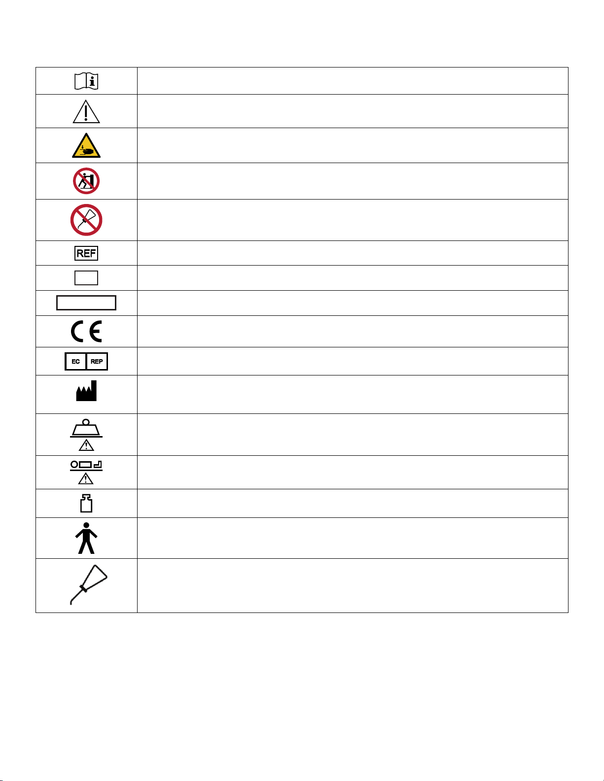
SSyymmbboollss
XXXX
Operating instructions/Consult instructions for use
Caution
Warning; crushing of hands
No pushing
Do not lubricate
Catalogue number
Serial number
For US Patents see www.stryker.com/patents
CE mark
EC REP
Manufacturer (XXXX indicates year of manufacture)
Safe working load
Maximum patient weight
Mass of equipment with safe working load
Type B applied part
Lubricate
SK 6300 Rev 01 EN


TTaabbllee ooff CCoonntteennttss
Warning/Caution/Note Definition ..............................................................................................................................3
Summary of safety precautions ................................................................................................................................4
Pinch points............................................................................................................................................................4
Introduction ...............................................................................................................................................................5
Product Description.................................................................................................................................................5
Indications for use...................................................................................................................................................5
Expected service life ...............................................................................................................................................5
Contraindications ....................................................................................................................................................6
Specifications .........................................................................................................................................................6
Product illustration ..................................................................................................................................................7
Applied parts ..........................................................................................................................................................8
Contact information .................................................................................................................................................8
Serial number location.............................................................................................................................................9
Preventive maintenance .........................................................................................................................................10
Retractable fifth wheel lubrication...........................................................................................................................12
Quick reference replacement parts ........................................................................................................................13
Service ....................................................................................................................................................................20
Raising the hood ................................................................................................................................................... 20
Replacing the hood ............................................................................................................................................... 20
Caster assembly replacement................................................................................................................................ 21
Brake rod replacement ..........................................................................................................................................22
Fifth wheel assembly replacement.......................................................................................................................... 23
Jack replacement.................................................................................................................................................. 24
Remove excess air from the hydraulic system .........................................................................................................26
Pump pedal replacement....................................................................................................................................... 26
Release pedal adjustment ..................................................................................................................................... 27
Release pedal replacement ................................................................................................................................... 28
Litter top removal .................................................................................................................................................. 29
Siderail latch replacement......................................................................................................................................30
X-ray cassette panel replacement - head end, ST1-X option..................................................................................... 30
X-ray cassette panel replacement - foot end, ST1-X option ...................................................................................... 31
Fowler gas cylinder replacement, ST1-X option .......................................................................................................32
Base assembly .......................................................................................................................................................34
Brake rod assembly - YM-660-320.........................................................................................................................40
Fifth wheel assembly - YM-660-123 .......................................................................................................................41
Lowering pedal assembly - YM-660-315................................................................................................................ 43
Pump pedal assembly - YM-660-037 ..................................................................................................................... 44
Litter frame assembly ............................................................................................................................................. 45
Litter mattress hook ................................................................................................................................................46
Litter assembly, ST1-X option ................................................................................................................................47
Fowler assembly, ST1-X option.............................................................................................................................. 49
Profile cap and Fowler guide part assembly........................................................................................................... 50
Left siderail assembly - YM-500-002 ...................................................................................................................... 51
Right siderail assembly - YM-500-003.................................................................................................................... 53
Left siderail latch assembly - YM-500-008 ............................................................................................................. 54
Right siderail latch assembly - YM-500-012...........................................................................................................55
Left spindle assembly - YM-500-006 ...................................................................................................................... 56
Right spindle assembly - YM-500-010.................................................................................................................... 57
Left latch spindle assembly - YM-500-007 ............................................................................................................. 58
SK 6300 Rev 01 1 EN

Right latch spindle assembly - YM-500-009...........................................................................................................59
Corner cover assembly...........................................................................................................................................60
Covers assembly, no options, head end ................................................................................................................ 62
Covers assembly with IV pole and pop-up push handles, head end .....................................................................63
Defibrillator tray assembly ......................................................................................................................................64
Two-stage IV pole assembly .................................................................................................................................. 65
Push handle assembly, head end ..........................................................................................................................66
Mattresses .............................................................................................................................................................. 67
EN 2 SK 6300 Rev 01

WWaarrnniinngg//CCaauuttiioonn//NNoottee DDeeffiinniittiioonn
The words WWAARRNNIINNGG, CCAAUUTTIIOONN, and NNOOTTEE carry special meanings and should be carefully reviewed.
WWAARRNNIINNGG -- Alerts the reader about a situation which, if not avoided, could result in death or serious injury. It may also
describe potential serious adverse reactions and safety hazards.
CCAAUUTTIIOONN -- Alerts the reader of a potentially hazardous situation which, if not avoided, may result in minor or moderate
injury to the user or patient or damage to the product or other property. This includes special care necessary for the safe
and effective use of the device and the care necessary to avoid damage to a device that may occur as a result of use or
misuse.
NNoottee -- Provides special information to make maintenance easier or important instructions clearer.
SK 6300 Rev 01 3 EN
SSuummmmaarryy ooff ssaaffeettyy pprreeccaauuttiioonnss
Always read and strictly follow the warnings and cautions listed on this page. Service only by qualified personnel.
CCAAUUTTIIOONN
• Improper usage of the product can cause injury to the patient or operator. Operate the product only as described in this
manual.
• Do not modify the product or any components of the product. Modifying the product can cause unpredictable operation
resulting in injury to patient or operator. Modifying the product also voids its warranty.
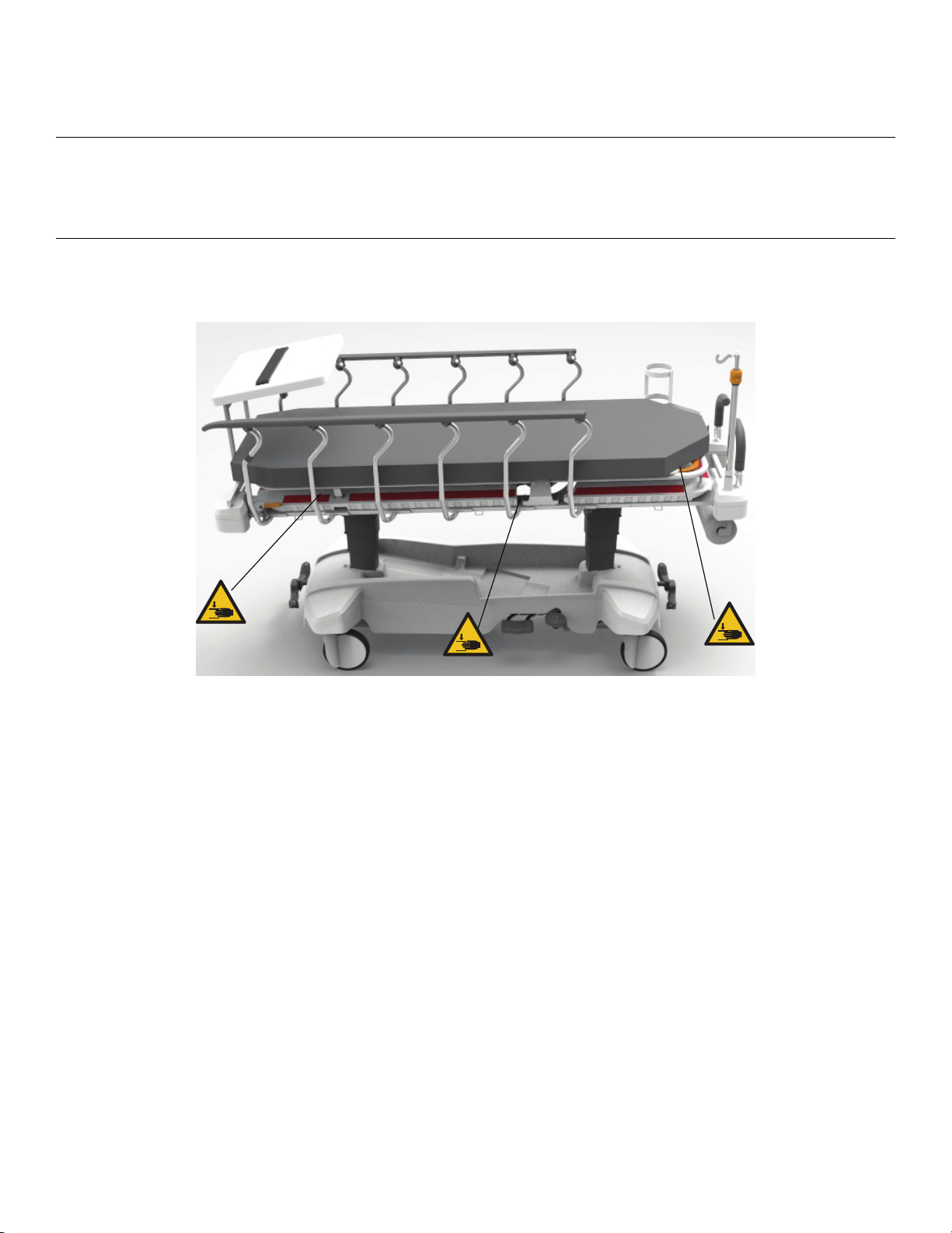
PPiinncchh ppooiinnttss
FFiigguurree 11 –– PPiinncchh ppooiinnttss ffoorr XX--rraayy ooppttiioonn oonnllyy
EN 4 SK 6300 Rev 01

IInnttrroodduuccttiioonn
This manual assists you with the operation or maintenance of your Stryker product. Read this manual before operating or
maintaining this product. Set methods and procedures to educate and train your staff on the safe operation or maintenance
of this product.
CCAAUUTTIIOONN
• Improper usage of the product can cause injury to the patient or operator. Operate the product only as described in this
manual.
• Do not modify the product or any components of the product. Modifying the product can cause unpredictable operation
resulting in injury to patient or operator. Modifying the product also voids its warranty.
NNoottee
• This manual is a permanent part of the product and should remain with the product even if the product is sold.
• Stryker continually seeks advancements in product design and quality. This manual contains the most current product
information available at the time of printing. There may be minor discrepancies between your product and this manual. If
you have any questions, contact Stryker Customer Service or Technical Support at 1-800-327-0770.
PPrroodduucctt DDeessccrriippttiioonn
The Stryker Model 6300 SSTT11 and SSTT11--XX Series stretcher is a wheeled device that consists of a platform mounted on a
wheeled frame to support patients in a horizontal position. The stretcher provides the operator with a method to transport
patients within the interior of a healthcare facility by health professionals or trained representatives of the facility. The
Stryker Model 6300 SSTT11 and SSTT11--XX Series stretcher with the retractable fifth wheel optimizes traction and cornering to
improve overall mobility.
IInnddiiccaattiioonnss ffoorr uussee
The stretcher is for use by human patients in a MedSurg setting, including those mildly to critically ill. The stretcher is for
use in hospitals, institutions, and clinics as a short-term outpatient clinical evaluation, treatment, minor procedure, and
short-term outpatient recovery platform. The stretcher may also be used to transport deceased patients within an enclosed
healthcare facility. Operators for the stretcher include healthcare professionals (nurses, nurse aides, and medical doctors)
and bystanders who can use bed motion functions (service or maintenance personnel).
The stretcher may include use in, but is not limited to:
• Emergency department (ED)
• Trauma area
• Post-anesthesia care unit (PACU)
The SSTT11 and SSTT11--XX Series stretcher is not for use for long-term (more than 24 hours) inpatient treatment and recovery.
The stretcher is not for use in a home healthcare environment.
The SSTT11 and SSTT11--XX Series stretcher frame, litter mounted accessories, mattresses, and siderails can contact human skin.
See the specifications table for the intended environmental conditions.
EExxppeecctteedd sseerrvviiccee lliiffee
The SSTT11 and SSTT11--XX Series stretcher with X-ray deck option has a 10 year expected service life under normal use,
conditions, and with appropriate periodic maintenance.
The casters have a minimum expected service life of 5 years dependent on normal use, conditions, and with appropriate
periodic maintenance.
SK 6300 Rev 01 5 EN
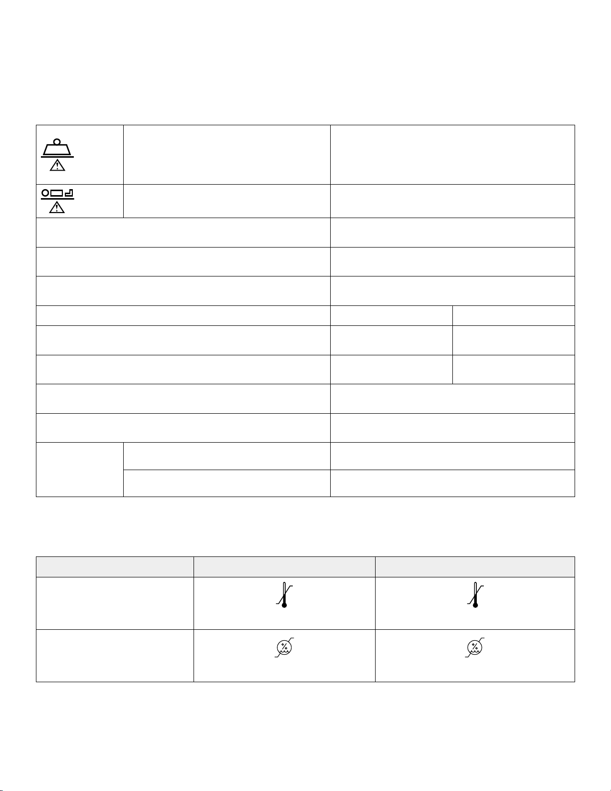
CCoonnttrraaiinnddiiccaattiioonnss
100 °F
(38 °C)
50 °F
(10 °C)
122 °F
(50 °C)
14 °F
(-10 °C)
75%
30%
90 %
20 %
None known.
SSppeecciiffiiccaattiioonnss
Safe working load indicates the sum of the
patient, mattress and accessory weight
250 kg
Maximum patient weight
Overall length
Overall width (siderails up)
Overall width (siderails down)
215 kg
2170 mm ± 10 mm
790 mm ± 10 mm
735 mm
Height Non X-ray X-ray
Minimum height
Maximum height
560 mm + 15 mm, - 25
mm
860 ± 10 mm
610 + 15 mm, - 25 mm
910 ± 10 mm
Fowler angle 0° to 90° (± 5°)
Trendelenburg/Reverse Trendelenburg +16°/-16° (± 3°)
Nominal
15.4 cm ± 5 mm
Minimum
clearance
Under the hydraulic jacks
4.6 cm ± 5 mm
Stryker reserves the right to change specifications without notice.
NNoottee -- This product is not suitable for use in the presence of a flammable anesthetic mixture with air or with oxygen or
nitrous oxide.
EEnnvviirroonnmmeennttaall ccoonnddiittiioonnss
OOppeerraattiioonn SSttoorraaggee aanndd ttrraannssppoorrttaattiioonn
Temperature
Relative humidity
Specifications listed are approximate and may vary slightly from product to product.
In accordance with the European REACH regulation and other environmental regulatory requirements, the components that
contain declarable substances are listed.
EN 6 SK 6300 Rev 01
DDeessccrriippttiioonn NNuummbbeerr SSuubbssttaannccee ooff vveerryy hhiigghh ccoonncceerrnn
A
B
C
D
E
F
G
H
I
J
K
L
M
B
A
N
((SSVVHHCC)) cchheemmiiccaall nnaammee
2 stage IV pole assembly 0785-035-101 bis(2-ethyklhexyl) phthatlate (DEHP)
2 stage IV pole assembly HM-19-108 bis(2-ethyklhexyl) phthatlate (DEHP)
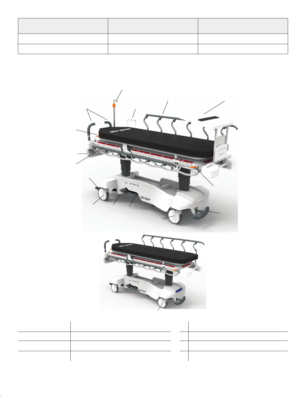
PPrroodduucctt iilllluussttrraattiioonn
A
B Caster I Siderail
C
D Fowler backrest release handle K
SK 6300 Rev 01 7 EN
Brake/steer control pedal
Defibrillator tray/chart holder
Pump pedal
H
J Siderail release handle
Uni-lower pedal
E
IV pole
Upright oxygen bottle holder
L
F
G
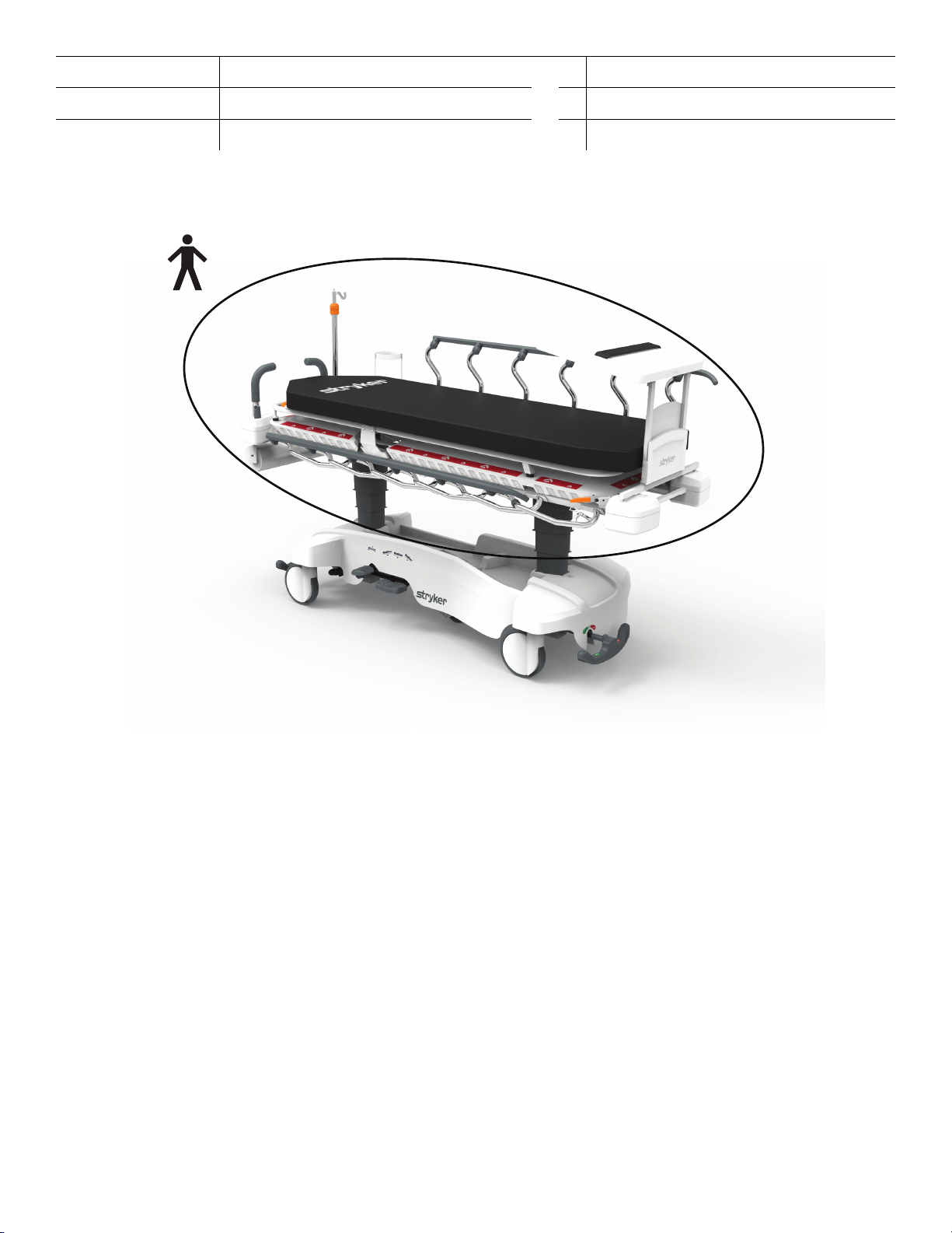
AApppplliieedd ppaarrttss
Pop up push handle
Paper roll holder
X-ray deck
M
Antistatic caster
N
FFiigguurree 22 –– TTyyppee BB aapppplliieedd ppaarrttss
CCoonnttaacctt iinnffoorrmmaattiioonn
Contact Stryker Customer Service or Technical Support at: +1 800-327-0770.
Stryker Medical International
Kayseri Serbest Bölge Şubesi
2. Cad. No:17 38070
Kayseri, Turkey
Email: infosmi@stryker.com
Phone: + 90 (352) 321 43 00 (pbx)
Fax: + 90 (352) 321 43 03
Web: www.stryker.com
To view your operations or maintenance manual online, see https://techweb.stryker.com/.
Have the serial number (A) of your Stryker product available when calling Stryker Customer Service or Technical Support.
Include the serial number in all written communication.
EN 8 SK 6300 Rev 01
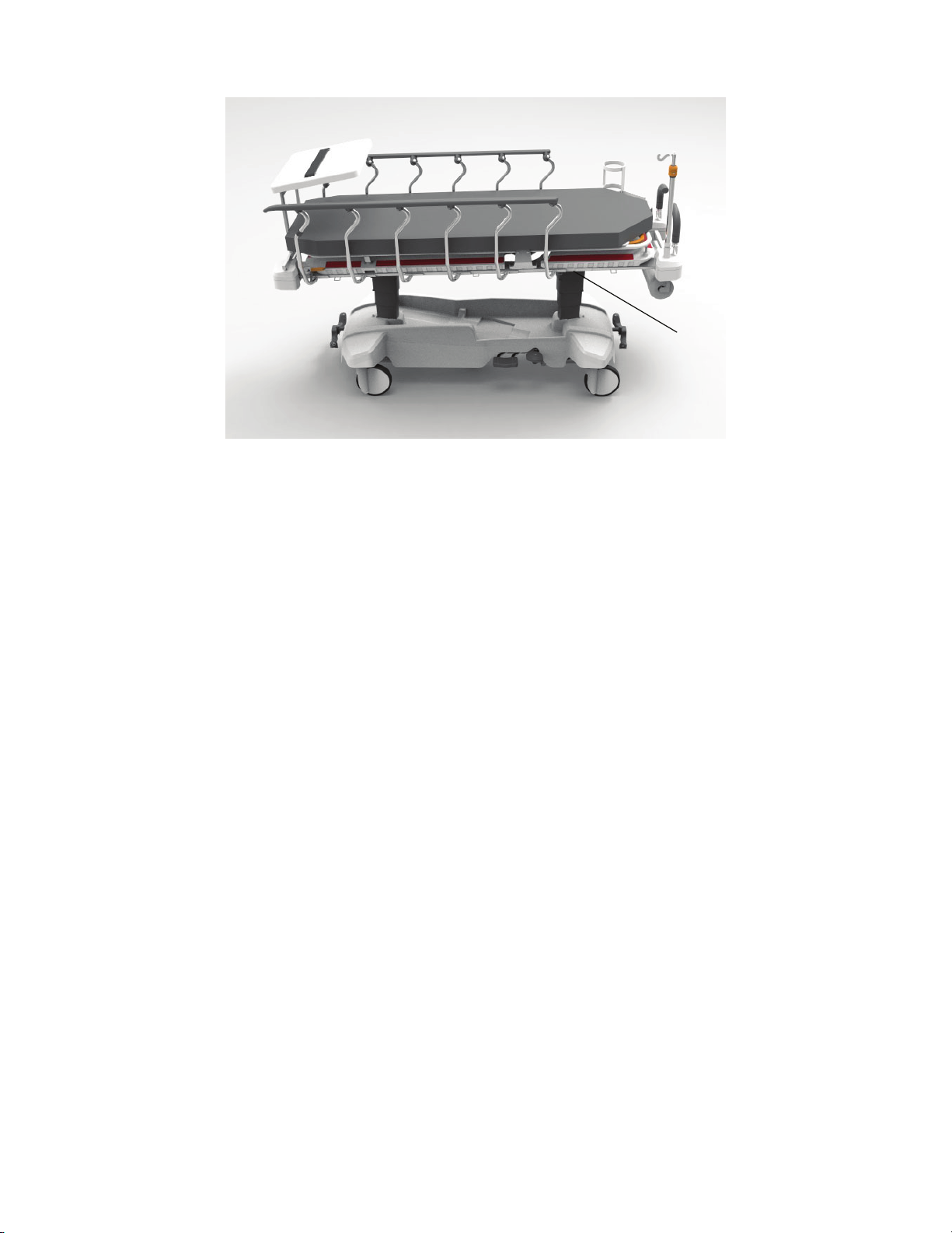
SSeerriiaall nnuummbbeerr llooccaattiioonn
A
FFiigguurree 33 –– SSeerriiaall nnuummbbeerr llooccaattiioonn
SK 6300 Rev 01 9 EN

PPrreevveennttiivvee mmaaiinntteennaannccee
Remove product from service before you perform the preventive maintenance inspection. Check all items listed during
annual preventive maintenance for all Stryker Medical products. You may need to perform preventive maintenance checks
more often based on your level of product usage. Service only by qualified personnel.
NNoottee -- Clean and disinfect the exterior of the mattress before inspection, if applicable.
Inspect the following items:
All welds
All fasteners are secure
All product labels are in place and legible
All weldments (base frame, brake, litter, jack, carriage, IV pole pivot weldment, and push handle weldments) are not
damaged
Siderails move and latch
Siderail latches are secure
Siderail is not damaged
Siderail latch is not damaged, no burrs or debris in latch assembly
Antistatic caster is not worn or damaged
Casters lock with brake pedal applied
Casters are secure and swivel
Casters are free of wax and debris
Casters are not worn or damaged
Caster mounting joint is not damaged
Casters, brake mechanism, and brake rod are not damaged or cracked
Fowler raises, lowers, and latches in place
Fowler does not drift or drop unexpectedly
No leaks at the Fowler backrest cyclinders
Fowler gas cylinder pin is not stuck
Brake/steer pedals are not bent or damaged
Brake mechanism works
Steer function works
Fifth wheel is not worn or damaged and works
Fifth wheel linkage is not bent or overtraveled
No debris or wax buildup in fifth wheel
Carriage bolt is secure
Base frame is not damaged
Pump pedal is not loose, worn, or damaged
Hydraulic release pedals are not loose or damaged
Jack release valve is free of dust, debris, does not stick
Jack linkages are not out of adjustment or damaged
Jack adjustment valves and spring work
Jacks are not damaged
Head end and foot end jacks raise and lower at the same time
EN 10 SK 6300 Rev 01

Litter raises and lowers from all locations
Litter components are in place and not damaged (fastener, holding pin, pin, bushing not backing out, loose, worn out,
or damaged)
Trendelenburg/Reverse Trendelenburg operates from all locations
Check skins for cracks
Hook and loop fastener is in place, intact, and secure
Fowler raises, lowers, and latches in place
Fowler subsystem (handle, wire, base weldment, cylinder, fasteners, etc. ) are not damaged
Hydraulic jacks are holding
No interference between wire and mechanical components on the Fowler backrest
No leaks at hydraulic connections
Lubricate where required
Push handles are not loose or damaged
Body restraints latch and are secure (optional)
IV pole is intact, is not damaged, and adjusts and latches in all positions (optional)
Oxygen bottle holder is intact and opens and closes (optional)
No rips or cracks in the mattress cover
Accessories and mounting hardware are in good condition
Product serial number:
Completed by:
Date:
SK 6300 Rev 01 11 EN
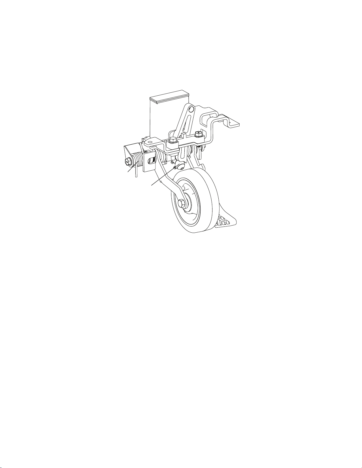
RReettrraaccttaabbllee ffiifftthh wwhheeeell lluubbrriiccaattiioonn
A
B
Tools required:
• MPG-3 grease
• Bungee cords
To lubricate the retractable fifth wheel:
1. Raise the product to the highest position.
FFiigguurree 44 –– RReettrraaccttaabbllee ffiifftthh wwhheeeell lluubbrriiccaattiioonn
2. Raise the base hood and support the hood with bungee cords.
3. Apply MPG-3 grease to the spring (A) and roller (B) (Figure 4).
4. Remove the bungee cords and lower the hood.
5. Verify proper operation before you return the product to service.
EN 12 SK 6300 Rev 01

QQuuiicckk rreeffeerreennccee rreeppllaacceemmeenntt ppaarrttss
These parts are currently available for purchase. Call Stryker Customer Service: + 90 (352) 321 43 00 (pbx) for availability
and pricing.
KKiitt nnaammee NNuummbbeerr KKiitt ccoonntteennttss
Fifth wheel
replacement kit
Low mech, foot end
replacement kit
Low mech, head end
replacement kit
Caster replacement
kit
NNuummbbeerr NNaammee
YM-KIT-100095 HM-05-057 M8 x 25 hexagon
head flange adhesive
applied bolt
HM-07-06 M8 large washer -
special
YM-660-123 Fifth wheel assembly 1
YM-KIT-100096 YM-660-201 Low mech foot side
wire assembly
HM-16-122 Ø20 x 46 x 2 mm
spring
HM-11-33 Ø6 rue clip 2
YM-KIT-100097 YM-660-203 Low mech backrest
side wire assembly
HM-16-122 Ø20 x 46 x 2 mm
spring
HM-11-33 Ø6 rue clip 2
YM-KIT-100098 YM-660-045 Caster fixing part 2
HM-01-68 2046 UAX 200 R36-
32S35 D RAL9003 4 x
M6 Grauweiss wheel
QQuuaannttiittyy
3
1
1
2
1
2
1
Lowering pedal
replacement kit
Pump pedal
replacement kit
Brake-steer pedal
replacement kit
HM-08-06 M8 Fibered nut 1
HM-06-001 M6 x 25 mushroom
head square neck bolt
HM-12-905 Flanged bronze
bushing
YM-KIT-100099 HM-12-019 Ø5,15 x Ø10 x 3,5
washer
HM-09-27 Ø5 x 18 dome head
rivet
HM-02-245 Short uni-pedal, cool
grey
YM-KIT-100100 HM-02-240 Pump pedal plastic,
cool grey
HM-12-009 Groove pin 1
YM-KIT-100101 HM-12-097 Ø6 drilled pin flange
head
HM-11-33 Ø6 rue clip 1
1
1
2
2
1
1
1
SK 6300 Rev 01 13 EN

KKiitt nnaammee NNuummbbeerr KKiitt ccoonntteennttss
Brake-steer mech
replacement kit
Base hood
replacement kit
NNuummbbeerr NNaammee
HM-02-246 Butterfly ‘V’ pedal 1
YM-KIT-100102 YM-660-320 Brake rod assembly 1
HM-05-057 M8 x 25 hexagon
head flange adhesive
applied bolt
YM-660-195 Brake rod crank cap 3
HM-11-33 Ø6 rue clip 3
HM-12-027 Ø6 x 26 clevis pin 3
YM-KIT-100103 HM-02-247 Base hood ST1-X 1
YM-660-249 Base hood dual lock
25 mm
YM-660-257 Base hood support
single notched
YM-660-248 Base hood support
double notched
YM-660-251 SGS branded dual
sided EVA tape
QQuuaannttiittyy
6
8
2
2
4
HM-02-138 Flush head plastic
rivet
HM-05-057 M8 x 25 hexagon
head flange adhesive
applied bolt
Pump replacement kit YM-KIT-100104 HM-18-06 Jack assembly 1
HM-05-043 M5*20 imbus bolt 2
YM-660-086 Release rod bearing 1
HM-05-114 M6 x 30 hexagon
socket head screw
HM-08-05 M6 fibered nut 4
HM-07-22 M6 steel washer
(small)
HM-05-057 M8 x 25 hexagon
head flange adhesive
applied bolt
Anti-static caster
YM-KIT-100105 YM-660-046 Caster fixing part 2
replacement kit
HM-01-69 2046 XSX 200 R36-
32S35 D RAL9003 4 x
M6 Grauweiss
antistatic wheel
3
2
4
8
4
1
HM-08-06 M8 fibered nut 1
HM-06-001 M6 x 25 mushroom
1
head square neck bolt
EN 14 SK 6300 Rev 01

KKiitt nnaammee NNuummbbeerr KKiitt ccoonntteennttss
Left siderail assembly
replacement kit
NNuummbbeerr NNaammee
HM-08-05 M6 fibered nut 1
HM-12-905 Flanged bronze
bushing
YM-660-127 Caster fixing part 1
HM-07-06 M8 large washer -
special
HM-07-22 M6 steel washer
(small)
YM-KIT-100106 YM-500-006 Left spindle assembly 5
YM-500-007 Left latch spindle
assembly
HM-09-34 Ø6,6 x 32 tubular
component
HM-09-35 5 x 12 aluminum blind
rivet
HM-05-002 M8 x 30 torx head
machine screw
QQuuaannttiittyy
1
1
1
1
6
6
6
Right siderail
assembly
replacement kit
HM-12-033 Spindle bearing 6
HM-02-257 Left toprail 1
HM-02-253 Spindle plug 6
HM-07-22 M6 steel washer
(small)
HM-08-05 M6 fibered nut 2
YM-KIT-100107 YM-500-010 Right spindle
assembly
YM-500-009 Right latch spindle
assembly
HM-09-34 Ø6,6 x 32 tubular
component
HM-09-35 5 x 12 aluminum blind
rivet
HM-05-002 M8 x 30 torx head
machine screw
HM-12-033 Spindle bearing 6
HM-02-258 Right toprail 1
4
5
1
6
6
6
HM-02-253 Spindle plug 6
HM-07-22 M6 steel washer
4
(small)
HM-08-05 M6 fibered nut 2
SK 6300 Rev 01 15 EN

KKiitt nnaammee NNuummbbeerr KKiitt ccoonntteennttss
Fowler assembly
replacement kit
NNuummbbeerr NNaammee
YM-KIT-100108 YM-500-060-BY Fowler weldment 1
HM-02-255 Fowler release handle 2
YM-500-041 Fowler laminated
sheet
HM-12-035 Handle pivot bushing 4
HM-02-259 Inner cable roller 2
HM-09-33 6 x 20 steel large
flange open end pop
rivet
HM-09-35 5 x 12 aluminum blind
rivet
HM-02-260 Outer cable roller 2
HM-02-263 Recessed bumper 2
YM-HM-02-436 Laminated sheet
spacer handle
HM-09-34 Ø6,6 x 32 tubular
component
QQuuaannttiittyy
1
4
6
2
4
Fowler cylinder
replacement kit
HM-16-125 Fowler cable
assembly
YM-HM-02-438 7 x 10 x 4 washer 4
YM-HM-02-268 10,4 x 16 x 10,7
spacer
HM-12-040 Ø6 x 52 clevis pin 1
HM-11-33 Ø6 rue clip 1
HM-18-07 Cylinder - 420 N 1
HM-19-106 Gas spring trip 1
HM-05-002 M8 x 30 torx head
machine screw
HM-12-036 Pivot bushing 2
HM-08-09 M8 hex nut 4
HM-11-35 Ø8 rue clip 1
HM-12-039 Ø8 x 70 clevis pin 1
YM-KIT-100109 YM-HM-02–268 10,4 x 16 x 10,7
spacer
1
2
2
2
HM-12-040 Ø6 x 52 clevis pin 1
HM-11-33 Ø6 rue clip 1
HM-18-07 Cylinder - 420 N 1
HM-19-106 Gas spring trip 1
EN 16 SK 6300 Rev 01

KKiitt nnaammee NNuummbbeerr KKiitt ccoonntteennttss
Foot end assembly
replacement kit
NNuummbbeerr NNaammee
HM-12-041 6,6 x 10 x 33 sleeve 1
HM-11-35 Ø8 rue clip 1
HM-12-039 Ø8 x 70 clevis pin 1
YM-KIT-100110 YM-500-062-BY Foot end weldment
assembly
YM-500-056 Footrest laminated
sheet
HM-02-263 Recessed bumper 2
HM-09-34 Ø6,6 x 32 tubular
component
HM-09-35 5 x 12 aluminum blind
rivet
YM-HM-02-438 7 x 10 x 4 washer 6
HM-05-002 M8 x 30 torx head
machine screw
HM-08-09 M8 hex nut 4
HM-12-036 Pivot bushing 2
QQuuaannttiittyy
1
1
6
8
2
Fowler tray
replacement kit
Foot end tray
replacement kit
YM-KIT-100111 YM-HM-02-434 Fowler tray 1
HM-20-1026 Right Fowler tray
label
HM-20-1027 Left Fowler tray label 1
HM-20-1028 Middle Fowler-foot
end tray label
HM-12-046 Hood latch 4
YM-KIT-100112 YM-HM-02-435 Foot end tray 1
HM-20-1028 Middle Fowler-foot
end tray label
HM-20-1029 Right foot end tray
label
HM-20-1030 Right foot end tray
short label
HM-20-1031 Left foot end tray label 1
HM-20-1032 Left foot end tray
short label
HM-12-046 Hood latch 4
1
1
1
1
1
1
Tray label
replacement kit
YM-KIT-100113 HM-20-1026 Right Fowler tray
label
1
HM-20-1027 Left Fowler tray label 1
SK 6300 Rev 01 17 EN

KKiitt nnaammee NNuummbbeerr KKiitt ccoonntteennttss
NNuummbbeerr NNaammee
HM-20-1028 Middle Fowler-foot
end tray label
HM-20-1029 Right foot end tray
label
HM-20-1030 Right foot end tray
short label
HM-20-1031 Left foot end tray label 1
HM-20-1032 Left foot end tray
short label
Bumper A cover kit YM-KIT-100114 YM-501-039 Bumper A upper
cover
YM-501-025 Bumper A bottom
cover
HM-05-060 4,8*25 Torx pan head
tapping screw ANSI
B18.6.4
Bumper B cover kit YM-KIT-100115 YM-501-024 Bumper B bottom
cover
YM-501-040 Bumper B upper
cover
QQuuaannttiittyy
2
1
1
1
1
1
3
1
1
Bumper A cover kit,
push handle
Bumper B cover kit,
push handle
HM-05-060 4,8*25 Torx pan head
tapping screw ANSI
B18.6.4
YM-KIT-100116 YM-501-025 Bumper A bottom
cover
YM-501-043 Bumper A upper
cover, push handle
HM-05-060 4,8*25 Torx pan head
tapping screw ANSI
B18.6.4
HM-05-002 M8 x 30 torx head
machine screw
YM-KIT-100117 YM-501-024 Bumper B bottom
cover
YM-501-044 Bumper B upper
cover, push handle
HM-05-060 4,8*25 Torx pan head
tapping screw ANSI
B18.6.4
HM-05-002 M8 x 30 torx head
machine screw
3
1
1
3
1
1
1
3
1
Bumper A cover kit,
IV pole
YM-KIT-100118 YM-501-025 Bumper A bottom
cover
YM-501-041 Bumper A upper
1
1
cover, IV pole
EN 18 SK 6300 Rev 01
 Loading...