

Page 1
Maintenance
Manual
Important
Information
File in your
maintenance
records
Medical
Transport Stretcher
Model ST104
For parts or technical
assistance call
800 327 0770 (option 2)
Page 2

Table of Contents
Introduction
Specifications 4. . . . . . . . . . . . . . . . . . . . . . . . . . . . . . . . . . . . . . . . . . . . . . . . . . . . . . . . . . . . . . . . . . . . . . . . . . . .
Warning / Caution / Note Definition 4. . . . . . . . . . . . . . . . . . . . . . . . . . . . . . . . . . . . . . . . . . . . . . . . . . . . . . . . .
Preventative Maintenance
Checklist 5. . . . . . . . . . . . . . . . . . . . . . . . . . . . . . . . . . . . . . . . . . . . . . . . . . . . . . . . . . . . . . . . . . . . . . . . . . . . . . . .
Cleaning 6. . . . . . . . . . . . . . . . . . . . . . . . . . . . . . . . . . . . . . . . . . . . . . . . . . . . . . . . . . . . . . . . . . . . . . . . . . . . . . . .
Service Information
Caster Cover Installation and Removal 7. . . . . . . . . . . . . . . . . . . . . . . . . . . . . . . . . . . . . . . . . . . . . . . . . . . . . .
Caster Removal 7. . . . . . . . . . . . . . . . . . . . . . . . . . . . . . . . . . . . . . . . . . . . . . . . . . . . . . . . . . . . . . . . . . . . . . . . . .
Brake Rod Removal 8. . . . . . . . . . . . . . . . . . . . . . . . . . . . . . . . . . . . . . . . . . . . . . . . . . . . . . . . . . . . . . . . . . . . . .
Side Control Brake Rod Removal 8. . . . . . . . . . . . . . . . . . . . . . . . . . . . . . . . . . . . . . . . . . . . . . . . . . . . . . . . . . .
Release Pedal Adjustment 9. . . . . . . . . . . . . . . . . . . . . . . . . . . . . . . . . . . . . . . . . . . . . . . . . . . . . . . . . . . . . . . .
Foot End Release Pedal Replacement 9. . . . . . . . . . . . . . . . . . . . . . . . . . . . . . . . . . . . . . . . . . . . . . . . . . . . . .
Foot End Release Pedal Rod Removal 9. . . . . . . . . . . . . . . . . . . . . . . . . . . . . . . . . . . . . . . . . . . . . . . . . . . . . .
Brake Ring Removal 10. . . . . . . . . . . . . . . . . . . . . . . . . . . . . . . . . . . . . . . . . . . . . . . . . . . . . . . . . . . . . . . . . . . . .
Fifth Wheel Assembly Removal 10. . . . . . . . . . . . . . . . . . . . . . . . . . . . . . . . . . . . . . . . . . . . . . . . . . . . . . . . . . .
Litter Top Removal 11. . . . . . . . . . . . . . . . . . . . . . . . . . . . . . . . . . . . . . . . . . . . . . . . . . . . . . . . . . . . . . . . . . . . . .
Jack Descent Rate Adjustment 11. . . . . . . . . . . . . . . . . . . . . . . . . . . . . . . . . . . . . . . . . . . . . . . . . . . . . . . . . . . .
Removal of Excess Air from the Hydraulic System 11. . . . . . . . . . . . . . . . . . . . . . . . . . . . . . . . . . . . . . . . . . .
Head End Hydraulic Jack Removal 12. . . . . . . . . . . . . . . . . . . . . . . . . . . . . . . . . . . . . . . . . . . . . . . . . . . . . . . .
Foot End Hydraulic Jack Removal 12. . . . . . . . . . . . . . . . . . . . . . . . . . . . . . . . . . . . . . . . . . . . . . . . . . . . . . . . .
Pneumatic Fowler Adjustment 13. . . . . . . . . . . . . . . . . . . . . . . . . . . . . . . . . . . . . . . . . . . . . . . . . . . . . . . . . . . .
Fold Down Siderail Latch Adjustment 13. . . . . . . . . . . . . . . . . . . . . . . . . . . . . . . . . . . . . . . . . . . . . . . . . . . . . .
Quick Reference Replacement Parts List 14. . . . . . . . . . . . . . . . . . . . . . . . . . . . . . . . . . . . . . . . . . . . . . . . . . . . .
Assembly Drawings and Parts Lists
Fifth Wheel Base Assembly 15. . . . . . . . . . . . . . . . . . . . . . . . . . . . . . . . . . . . . . . . . . . . . . . . . . . . . . . . . . . . . .
Page 3

Table of Contents
Assembly Drawings (Continued)
Fifth Wheel Assembly 16, 17. . . . . . . . . . . . . . . . . . . . . . . . . . . . . . . . . . . . . . . . . . . . . . . . . . . . . . . . . . . . . . . . .
Base Assembly with Standard Brakes 18, 19. . . . . . . . . . . . . . . . . . . . . . . . . . . . . . . . . . . . . . . . . . . . . . . . . . .
Brake Rod Assembly 20. . . . . . . . . . . . . . . . . . . . . . . . . . . . . . . . . . . . . . . . . . . . . . . . . . . . . . . . . . . . . . . . . . . .
Drive Link Assembly 21, 22. . . . . . . . . . . . . . . . . . . . . . . . . . . . . . . . . . . . . . . . . . . . . . . . . . . . . . . . . . . . . . . . . .
Caster Assembly 23. . . . . . . . . . . . . . . . . . . . . . . . . . . . . . . . . . . . . . . . . . . . . . . . . . . . . . . . . . . . . . . . . . . . . . . .
Base Assembly with Four−Sided Brakes 24, 25. . . . . . . . . . . . . . . . . . . . . . . . . . . . . . . . . . . . . . . . . . . . . . . .
Brake Rod Assembly 26. . . . . . . . . . . . . . . . . . . . . . . . . . . . . . . . . . . . . . . . . . . . . . . . . . . . . . . . . . . . . . . . . . . .
Side Control Brake Rod Assembly 27. . . . . . . . . . . . . . . . . . . . . . . . . . . . . . . . . . . . . . . . . . . . . . . . . . . . . . . . .
Base Assembly with Dual Side Hydraulics 28−30. . . . . . . . . . . . . . . . . . . . . . . . . . . . . . . . . . . . . . . . . . . . . . .
Release Pedal Assembly 31. . . . . . . . . . . . . . . . . . . . . . . . . . . . . . . . . . . . . . . . . . . . . . . . . . . . . . . . . . . . . . . . .
Pump Pedal Assembly 32. . . . . . . . . . . . . . . . . . . . . . . . . . . . . . . . . . . . . . . . . . . . . . . . . . . . . . . . . . . . . . . . . . .
Variable Descent Hydraulic Jack Option 33. . . . . . . . . . . . . . . . . . . . . . . . . . . . . . . . . . . . . . . . . . . . . . . . . . . .
Jack Base Assembly, Variable Descent Jacks 34. . . . . . . . . . . . . . . . . . . . . . . . . . . . . . . . . . . . . . . . . . . . . . .
Base Labeling Assembly 36−38. . . . . . . . . . . . . . . . . . . . . . . . . . . . . . . . . . . . . . . . . . . . . . . . . . . . . . . . . . . . . .
Litter Assembly 39−41. . . . . . . . . . . . . . . . . . . . . . . . . . . . . . . . . . . . . . . . . . . . . . . . . . . . . . . . . . . . . . . . . . . . . .
Siderail Assembly 42. . . . . . . . . . . . . . . . . . . . . . . . . . . . . . . . . . . . . . . . . . . . . . . . . . . . . . . . . . . . . . . . . . . . . . .
Fowler to Frame Assembly 43. . . . . . . . . . . . . . . . . . . . . . . . . . . . . . . . . . . . . . . . . . . . . . . . . . . . . . . . . . . . . . .
Pneumatic Fowler Assembly 44. . . . . . . . . . . . . . . . . . . . . . . . . . . . . . . . . . . . . . . . . . . . . . . . . . . . . . . . . . . . . .
Pneumatic Fowler Outer Housing Assembly 45. . . . . . . . . . . . . . . . . . . . . . . . . . . . . . . . . . . . . . . . . . . . . . . .
Foot End Push Handles 46. . . . . . . . . . . . . . . . . . . . . . . . . . . . . . . . . . . . . . . . . . . . . . . . . . . . . . . . . . . . . . . . . .
Head End Push Handles 47. . . . . . . . . . . . . . . . . . . . . . . . . . . . . . . . . . . . . . . . . . . . . . . . . . . . . . . . . . . . . . . . .
Push Handle Assembly 48. . . . . . . . . . . . . . . . . . . . . . . . . . . . . . . . . . . . . . . . . . . . . . . . . . . . . . . . . . . . . . . . . .
Removable I.V. Pole Assembly 49. . . . . . . . . . . . . . . . . . . . . . . . . . . . . . . . . . . . . . . . . . . . . . . . . . . . . . . . . . . .
2−Stage I.V. Assembly 50−51. . . . . . . . . . . . . . . . . . . . . . . . . . . . . . . . . . . . . . . . . . . . . . . . . . . . . . . . . . . . . . . .
I.V. Pole Latch 52. . . . . . . . . . . . . . . . . . . . . . . . . . . . . . . . . . . . . . . . . . . . . . . . . . . . . . . . . . . . . . . . . . . . . . . . . .
3−Stage I.V. Assembly 53−55. . . . . . . . . . . . . . . . . . . . . . . . . . . . . . . . . . . . . . . . . . . . . . . . . . . . . . . . . . . . . . . .
Optional Defibrillator Tray Assembly 56. . . . . . . . . . . . . . . . . . . . . . . . . . . . . . . . . . . . . . . . . . . . . . . . . . . . . . .
Foot Extension/Defibrillator Tray Assembly 57. . . . . . . . . . . . . . . . . . . . . . . . . . . . . . . . . . . . . . . . . . . . . . . . .
Foot Board / Chartholder Assembly
Upright Oxygen Bottle Holder Assembly 58. . . . . . . . . . . . . . . . . . . . . . . . . . . . . . . . . . . . . . . . . . . . . . . . . . . .
Optional Oxygen Bottle Retainer Assembly 59. . . . . . . . . . . . . . . . . . . . . . . . . . . . . . . . . . . . . . . . . . . . . . . . .
Mattresses and Siderail Pads 60−61. . . . . . . . . . . . . . . . . . . . . . . . . . . . . . . . . . . . . . . . . . . . . . . . . . . . . . . . . .
58. . . . . . . . . . . . . . . . . . . . . . . . . . . . . . . . . . . . . . . . . . . . . . . . . . . . . . . .
Page 4

Table of Contents
Warranty
Obtaining Parts and Service 62. . . . . . . . . . . . . . . . . . . . . . . . . . . . . . . . . . . . . . . . . . . . . . . . . . . . . . . . . . . . . .
Service Contract Coverage 62. . . . . . . . . . . . . . . . . . . . . . . . . . . . . . . . . . . . . . . . . . . . . . . . . . . . . . . . . . . . . . .
Return Authorization 63. . . . . . . . . . . . . . . . . . . . . . . . . . . . . . . . . . . . . . . . . . . . . . . . . . . . . . . . . . . . . . . . . . . . .
Freight Damage Claims 63. . . . . . . . . . . . . . . . . . . . . . . . . . . . . . . . . . . . . . . . . . . . . . . . . . . . . . . . . . . . . . . . . .
Page 5

Introduction
INTRODUCTION
This manual is designed to assist you with the operation of the Model 735 Transport Stretcher. Read it thoroughly before using the equipment or beginning any maintenance on it.
SPECIFICATIONS
Maximum Weight Capacity 500 pounds
Overall Stretcher Length \ Width 83” / 30”
Minimum \ Maximum Bed Height 21.5” / 36”
Fowler Angle 0 to 90
Trendelenburg \ Reverse Trendelenburg +18 to −18
Stryker reserves the right to change specifications without notice.
WARNING / CAUTION / NOTE DEFINITION
The words WARNING, CAUTION and NOTE carry special meanings and should be carefully reviewed.
WARNING
Alerts the reader about a situation, which if not avoided, could result in death or serious injury. It may also
describe potential serious adverse reactions and safety hazards.
CAUTION
Alerts the reader of a potentially hazardous situation, which if not avoided, may result in minor or moderate
injury to the user or patient or damage to the equipment or other property. This includes special care necessary for the safe and effective use of the device and the care necessary to avoid damage to a device that
may occur as a result of use or misuse.
NOTE
This provides special information to make maintenance easier or important instructions clearer.
Safe Working Load
Return to Table of Contents
4
Page 6

Preventative Maintenance
CHECKLIST
All fasteners secure
Siderails move and latch properly
Engage the brake pedal and push on the stretcher to ensure all casters lock securely
All casters secure and swiveling properly
Body restraints working properly
I.V. pole intact and operating properly
Oxygen bottle holder intact and operating properly
Fowler operates and latches properly
Trendelenburg/Reverse Trendelenburg operating properly
No rips or cracks in mattress cover
Transfer boards intact and operating properly
Ground chain intact
No leaks at hydraulic connections
Hydraulic jacks holding properly
Hydraulic drop rate set properly
Hydraulic oil level sufficient
Lubricate where required
Accessories and mounting hardware in good condition and working properly
Serial No. ______________
______________
______________
______________
______________
Completed By:_________________________________ Date:_____________
NOTE
Preventative maintenance should be performed at a minimum of annually. A preventative maintenance program should be established for all Stryker Medical equipment. Preventative maintenance may need to be
performed more frequently based on the usage level of the product.
Return to Table of Contents
5
Page 7

Cleaning
Hand wash all surfaces of the stretcher with warm water and mild detergent. DRY THOROUGHLY. Do not
steam clean, pressure wash, hose off or ultrasonically clean. Using these methods of cleaning is not recommended and may void this product’s warranty.
Suggested cleaners for stretcher surfaces:
Quaternary Cleaners (active ingredient − ammonium chloride)
Phenolic Cleaners (active ingredient − o−phenylphenol)
Chlorinated Bleach Solution (5.25% − less than 1 part bleach to 100 parts water)
Avoid oversaturation and ensure the product does not stay wet longer than the chemical manufacturer ’s
guidelines for proper disinfecting.
CAUTION
SOME CLEANING PRODUCTS ARE CORROSIVE IN NATURE AND MAY CAUSE DAMAGE TO THE
PRODUCT IF USED IMPROPERLY. If the products described above are used to clean Stryker patient care
equipment, measures must be taken to insure the beds are wiped with clean water and thoroughly dried following cleaning. Failure to properly rinse and dry the beds will leave a corrosive residue on the surface of
the bed, possibly causing premature corrosion of critical components. Failure to follow the above directions
when using these types of cleaners may void this product’s warranty.
For mattress cleaning instructions, please see the tag on the mattress, or contact the mattress manufacturer.
Clean Velcro AFTER EACH USE. Saturate Velcro with disinfectant and allow disinfectant to evaporate.
(Appropriate disinfectant for nylon Velcro should be determined by the hospital.
Return to Table of Contents
6
Page 8
Service Information
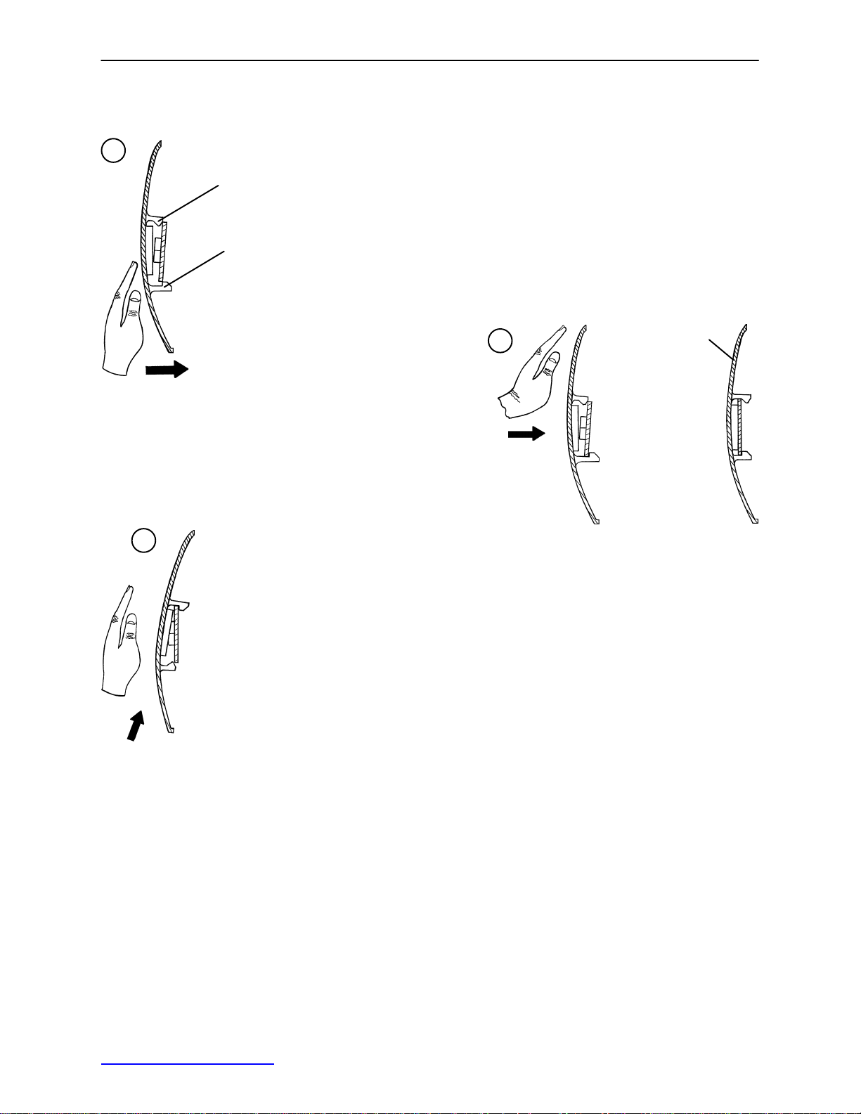
CASTER COVER INSTALLATION AND REMOVAL
1.
Double Prongs
Looking through the larger of the two side cut−outs,
align the cover with the axle nut or bolt head, as shown.
Single Prong
Push down on the opposite side of the cover until the
single prong engages the caster horn.
3.
Top View (Cut−A way)
Push on the cover with your palm until
the double prongs engage.
To remove the wheel cover, insert a large screwdriver into the cut−out
in the side of the wheel cover and into the space between the double
prongs. Pry up the cover to disengage the double prongs and push
sharply upward to disengage the single prong.
Top View (Cut−A way)
2.
Properly Attached
Cover
Top View (Cut−A way)
CASTER REMOVAL
Required Tools:
9/16” Open End Wrench
1. Remove the caster cover.
2. While keeping pressure on the caster bolt with your index finger, use a 9/16” open end wrench to remove
the nylock hex nut on top of the caster assembly.
3. Using the brake ring, lift up on the base assembly and pull the caster assembly down to remove it.
4. Reverse steps 1−3 to install the new caster.
Return to Table of Contents
7
Page 9

Service Information
BRAKE ROD REMOVAL
Required Tools:
Hammer 7/32” Punch String or Bungee Cords
1. Pump the litter up to full height.
2. Lift the base hood and support it from the litter using string or bungee cords.
3. Remove the hex head cap screws connecting the brake rod supports to the base frame.
4. Remove the bolt connecting the drive link assembly to the fifth wheel cam.
5. Remove the rue ring cotter and clevis pin connecting the rod end link to the side control link.
6. Remove the rue ring cotter connecting the drive link assembly to the bearing pivot support on the base
frame (under the brake ring weldment).
7. Remove the three hex washer head screws holding the brake rod assembly to the base frame.
8. Remove the slotted spring pins connecting the butterfly “V” pedals, drive link assemblies and side control
link to the brake rod.
9. Reverse steps 1−8 to reinstall the brake rod. When reinstalling the brake rod supports, torque the hex
head cap screws to 12−15 ft.−lbs.
CAUTION
When reattaching the brake rod assembly to the base frame, set the torque specs no higher than 15 ft.−lbs.
or damage could occur to the bolts.
SIDE CONTROL BRAKE ROD REMOVAL
Required Tools:
1. Pump the litter up to full height.
2. Lift the base hood and support it from the litter using string or bungee cords.
3. Remove the rue ring cotter and clevis pin connecting the rod end link to the side control link.
4. Remove the four bolts holding the brake rod assembly to the base frame and remove the entire assembly.
5. Using a hammer and 7/32” punch, drive the slotted spring pin out of the butterfly “V” pedal on the patient’s
left side and remove the pedal,
6. Using a hammer and 7/32” punch, drive the slotted spring pin out of the hard stop in the center of the
support weldment.
7. Using a hammer and 7/32” punch, drive out the slotted spring pin connecting the side control link to the
side control brake rod on the patient’s right side.
8. Pull on the butterfly “V” pedal on the patient’ s right side to remove the side control brake rod from the base.
Hammer 7/32” Punch Needle Nose Pliers String or Bungee Cords
9. Reverse steps 1−8 to reinstall the brake rod. When reinstalling the assembly, torque the hex head cap
screws to 12−15 ft.−lbs.
CAUTION
When reattaching the brake rod assembly to the base frame, set the torque specs no higher than 15 ft.−lbs.
or damage could occur to the bolts.
Return to Table of Contents
8
Page 10

Service Information
RELEASE PEDAL ADJUSTMENT
1. Manually disengage the release pedal swivel (item J on page 29) from the release pedal assembly.
2. To increase the release rod engagement with the release valve, turn the release pedal swivel clockwise
on the threaded release rod.
3. To decrease the release rod engagement with the release valve, turn the release pedal swivel counterclockwise on the threaded release rod.
NOTE
If the pedal swivel assembly is threaded too far onto the release rod, the release valve will be partially activated and the jack will drift.
FOOT END RELEASE PEDAL REPLACEMENT
Required Tools:
1. Apply the stretcher brakes.
2. Disconnect the release pedal return springs from the foot end release pedals.
3. Remove the rue ring cotters and the clevis pins connecting the foot end release pedals to the mounting
bracket.
4. Rotate the pedals upward.
5. Remove the rue ring cotters connecting the head end and foot end release rods to the foot end release
pedals and remove the pedals.
6. Reverse steps 2−5 to install the new pedals.
Needle Nose Pliers
FOOT END RELEASE PEDAL ROD REMOVAL
Required Tools:
1. Remove the foot end release pedal (see procedure above).
2. Remove the snap in nyliners holding the foot end pedal release rods in the pedal mounting bracket.
3. Unsnap the foot end pedal release rods from the white plastic release rod brackets.
Needle Nose Pliers
4. Dislodge the side control release pedal swivels from the studs on the side control release pedal weldments.
5. Remove the foot end pedal release rods.
6. Reverse steps 1−5 to reinstall the pedal rods.
Return to Table of Contents
9
Page 11

Service Information
BRAKE RING REMOVAL
Required Tools:
9/16” Socket w/Extension 3/8” Drive Ratchet Needle−Nose Pliers String or Bungee Cord
1. Pump the litter up to full height.
2. Lift the base hood and support it from the litter using string or bungee cords.
3. Using needle−nose pliers, unhook the extension springs from the top of the base caster tubes.
4. Remove the plastic caster covers.
5. While putting pressure on the caster carriage bolt, use a 9/16” socket and a 3/8” drive ratchet to remove
the caster nut on both sides of the stretcher.
6. Remove the casters.
7. Remove the brake rod (see procedure).
8. Remove the cotter pin from the clevis pin in the center of the brake ring weldment.
9. Remove the cotter pin from the bearing pivot support.
10. Remove the 3/4” nylock hex nut from the bearing pivot support.
11. Remove the drive link assembly.
12. Pull the brake ring down and out away from the stretcher base frame.
13. Reverse steps 1−12 to reinstall the brake ring.
FIFTH WHEEL ASSEMBLY REMOVAL
Required Tools:
1/2” Socket 3/8” Drive Ratchet
1. Using a 1/2” socket and 3/8” drive ratchet, remove the 1/2” bolt holding the fifth wheel cam drive link and
fifth wheel drive link to the fifth wheel cam.
2. Remove the two 1/2” bolts holding the fifth wheel mounting bracket to the base frame weldment.
3. Remove the fifth wheel assembly.
4. Reverse steps 1 and 2 to reinstall the fifth wheel. When reinstalling the assembly , torque the hex head
cap screws to 12−15 ft.−lbs.
CAUTION
When reattaching the fifth wheel assembly to the base frame, set the torque specs no higher than 15 ft.−lbs.
or damage could occur to the bolts.
Return to Table of Contents
10
Page 12

LITTER TOP REMOVAL
Service Information
Required Tools:
1. Using the foot pedal, pump up the litter top to full height.
2. Remove the stretcher mattress
3. Remove the round, black hole plugs from the jack supports at each end of the litter to expose the jack
support tube truss head screws.
4. Using a 1/2” socket, and a 3/8” drive ratchet, remove the truss head screws holding the jack support tubes
to the jack shafts.
5. Thread a 7/16−20 fine thread bolt far enough into the top of the jack supports to separate the litter top
from the jack shaft.
6. With the assistance of another person, lift the litter straight up to remove it from the jack shafts and set
it aside.
1/2” Socket w/Extension 3/8” Drive Ratchet Standard Screwdriver
JACK DESCENT RATE ADJUSTMENT
Required Tools:
Screwdriver Bungee Cords (or equivalent)
Adjustment Procedure:
1. Pump the litter up to full height.
2. Lift the base hood, separating the hood from the base frame. Support the hood from the litter using bungee cords so it is out of the way.
3. The descent rate needle valve is located on the base of the jack. Turning the needle valve clockwise,
with a screwdriver, will decrease the rate of descent. Turning it counterclockwise will increase the rate
of descent.
NOTE
The larger percentage of a patient’s weight is located in the torso area. Adjust descent rate accordingly.
4. Remove the bungee cords supporting the base hood and secure the hood to the base frame.
NOTE
The jack descent rate is preset at the factory and adjustment is not recommended.
REMOVAL OF EXCESS AIR (VACUUM) FROM THE HYDRAULIC SYSTEM
1. Verify all hydraulic linkages are secure and operating properly.
2. Using the pump pedal, actuate the system several times to force the air through the system. The jack
should now raise properly.
Return to Table of Contents
11
Page 13

Service Information
HEAD END HYDRAULIC JACK REMOVAL
Required Tools:
1. Remove the litter top from the stretcher (see page 11).
2. Using a 1/2” socket with extension and a 3/8” drive ratchet, remove the two hex head screws holding the
jack base to the stretcher base frame.
3. Remove the two hex head screws holding the jack reservoir clamp to the base frame and remove the
clamps.
4. Lift straight up on the pump connecting rod and disconnect the pump piston from the connecting rod.
5. Disconnect the pump pedal swivel from the release pedal mounting plate.
6. Remove the head end release rod from the release valve assembly.
7. Using a 1/2” socket with extension and a 3/8” drive ratchet, remove the two hex head screws holding the
jack base to the stretcher base frame.
8. Lift out the jack assembly.
9. To reinstall the jack, install the bolts on the jack and reservoir clamp but do not tighten them fully.
10. Reinstall the pump connecting rod and release rod.
11. Depress the pump pedal fully (to the floor). This will properly locate the jack onto the base frame.
12. Tighten the bolts on the jack and reservoir clamp.
13. Pump up the litter and apply weight to verify the jacks hold and do not drift.
1/2” Socket w/Extension 3/8” Drive Ratchet
NOTE
The jack descent rate is preset at the factory and adjustment is not recommended.
FOOT END HYDRAULIC JACK REMOVAL (BASE WITH DUAL CONTROLS)
Required Tools:
1/2” Socket 3/8” Drive Ratchet Pliers
1. Remove the litter top from the stretcher (see page 11).
2. Lift the base hood off the base frame.
3. Remove the two hex washer head screws and washers connecting the pump pedal link to the foot end
pump pedal assembly and pump connecting rod.
4. Remove the foot end release rod from the release valve on the jack assembly by dislodging the release
pedal swivel from the pins on the release pedal weldment.
5. Dislodge the jack pump piston from the pump connecting rod.
6. Remove the two hex washer head screws holding the reservoir clamp.
7. Remove the jack assembly.
8. Reverse steps 1−7 to install the new jack.
NOTE
The jack descent rate is preset at the factory and adjustment is not recommended.
Return to Table of Contents
12
Page 14

Service Information
PNEUMATIC FOWLER ADJUSTMENT
Required Tools:
5/32” Hex Allen Wrench 1/2” Open End Wrench
1. Refer to the pneumatic Fowler assembly drawing on page 44 for parts reference.
2. For easier access, raise the Fowler to 75 or higher.
3. Using a 1/2” open end wrench, loosen the hex nuts (item E) in the actuator arms on the end of the trip
bar (item M).
4. To adjust the Fowler, use a 5/32” hex Allen wrench to turn the Allen screws (item J) 1 to 2 turns counter−clockwise if the Fowler will not move or 1 to 2 turns clockwise if the Fowler will not hold its position.
5. Retighten the hex nuts. Be sure the Fowler travels from flat up to 90 and down again and holds its position when weight is applied before returning the stretcher to service.
FOLDDOWN SIDERAIL LATCH ADJUSTMENT
Required Tools:
1/8” Hex Allen Wrench
WARNING
The siderail latches are preset at the factory, and do not normally need adjustment. If adjustment must be
done, it is important to follow the procedure below. If adjustment is not done properly, injury to the patient
or user could result.
1. Using a 1/8” hex Allen wrench, adjust the hex Allen screw located on the latch assembly opposite the latch. Turning the screw clockwise will DECREASE the amount of ”play” in the latching mechanism. Turning counterclockwise will INCREASE the amount.
NOTE
The amount of ”play” in the siderail, when in full up engaged position, should be approximately 1/8 to 3/16
inches.
CAUTION
Too much ”play” when the siderail is in the full up engaged position will give the siderail the appearance of
being unstable and could also cause premature wearing of the latch system.
Too little ”play” will obstruct the latch and keep it from engaging completely in the full up position, which may
result in damage to the latch and/or injury to the patient or user.
Return to Table of Contents
13
Page 15

Quick Reference Replacement Parts List
PART NAME PART NUMBER
Caster Assembly (1 complete) 0753−010−020. . . . . . . . . . . . . . . . . . . . . . . . . . . . . . . . . . . . . . . . . . . . . . . .
Chartholder 0946−028−100. . . . . . . . . . . . . . . . . . . . . . . . . . . . . . . . . . . . . . . . . . . . . . . . . . . . . . . . . . . . . . . . .
Defibrillator Tray/Foot Extension 1010−050−100. . . . . . . . . . . . . . . . . . . . . . . . . . . . . . . . . . . . . . . . . . . . . . .
Foot Board/Chartholder Combination 0926−040−100. . . . . . . . . . . . . . . . . . . . . . . . . . . . . . . . . . . . . . . . . . .
Foot Board (1 per package) 0946−029−001. . . . . . . . . . . . . . . . . . . . . . . . . . . . . . . . . . . . . . . . . . . . . . . . . . .
Foot Board (2 per package) 0946−029−100. . . . . . . . . . . . . . . . . . . . . . . . . . . . . . . . . . . . . . . . . . . . . . . . . . .
Hydraulic Jack Assembly, Variable Descent 0753−002−170. . . . . . . . . . . . . . . . . . . . . . . . . . . . . . . . . . . . .
I.V. Pole, Standard Removable 0390−025−000. . . . . . . . . . . . . . . . . . . . . . . . . . . . . . . . . . . . . . . . . . . . . . .
I.V. Pole Kit, Permanent 2−Stage, Head and Foot End 0721−400−001. . . . . . . . . . . . . . . . . . . . . . . . . . . .
I.V. Pole, Permanent 3−Stage, Head End 0721−061−000. . . . . . . . . . . . . . . . . . . . . . . . . . . . . . . . . . . . . . .
I.V. Pole, Permanent 3−Stage, Foot End 0721−062−000. . . . . . . . . . . . . . . . . . . . . . . . . . . . . . . . . . . . . . . .
Mattress, 3” x 26”, Standard 1059−326−140. . . . . . . . . . . . . . . . . . . . . . . . . . . . . . . . . . . . . . . . . . . . . . . . . .
Mattress, 4” x 26”, Standard 1059−426−140. . . . . . . . . . . . . . . . . . . . . . . . . . . . . . . . . . . . . . . . . . . . . . . . . .
Mattress, 3” x 26”, Enhanced Comfort 1001−048−106. . . . . . . . . . . . . . . . . . . . . . . . . . . . . . . . . . . . . . . . . .
Mattress, 4” x 26”, Enhanced Comfort 1001−047−106. . . . . . . . . . . . . . . . . . . . . . . . . . . . . . . . . . . . . . . . . .
Mattress, 4” x 26”, Ultra Comfort 1210−040−004. . . . . . . . . . . . . . . . . . . . . . . . . . . . . . . . . . . . . . . . . . . . . .
Mattress, 5” x 26”, Ultra Comfort 1210−040−005. . . . . . . . . . . . . . . . . . . . . . . . . . . . . . . . . . . . . . . . . . . . . .
Oxygen Bottle Holder, Upright 1020−030−000. . . . . . . . . . . . . . . . . . . . . . . . . . . . . . . . . . . . . . . . . . . . . . . . .
Paint, Touch−Up, Gloss Black, Bottle w/Brush 7000−001−322. . . . . . . . . . . . . . . . . . . . . . . . . . . . . . . . . . .
Paint, Touch−Up, Gloss Black, Spray Can 7000−001−319. . . . . . . . . . . . . . . . . . . . . . . . . . . . . . . . . . . . . .
Paint, Touch−Up, Gray, Bottle w/Brush 7000−001−320. . . . . . . . . . . . . . . . . . . . . . . . . . . . . . . . . . . . . . . . .
Paint, Touch−Up, Gray, Spray Can 7000−001−317. . . . . . . . . . . . . . . . . . . . . . . . . . . . . . . . . . . . . . . . . . . . .
Pneumatic Cylinder 1010−031−078. . . . . . . . . . . . . . . . . . . . . . . . . . . . . . . . . . . . . . . . . . . . . . . . . . . . . . . . . .
Restraint Strap, Ankle 0946−043−100. . . . . . . . . . . . . . . . . . . . . . . . . . . . . . . . . . . . . . . . . . . . . . . . . . . . . . . .
Restraint Straps, Body 0390−019−000. . . . . . . . . . . . . . . . . . . . . . . . . . . . . . . . . . . . . . . . . . . . . . . . . . . . . . .
Restraint Strap, Wrist 0946−044−100. . . . . . . . . . . . . . . . . . . . . . . . . . . . . . . . . . . . . . . . . . . . . . . . . . . . . . . .
Siderail Pad Set 1010−052−000. . . . . . . . . . . . . . . . . . . . . . . . . . . . . . . . . . . . . . . . . . . . . . . . . . . . . . . . . . . . .
NOTE
The parts and accessories listed on this page are all currently available for purchase. Some of the parts identified on the assembly drawings pages in this manual may not be individually available for purchase. Please
call Stryker Customer Service at 1−800−327−0770 for availability and pricing.
Return to Table of Contents
14
Page 16
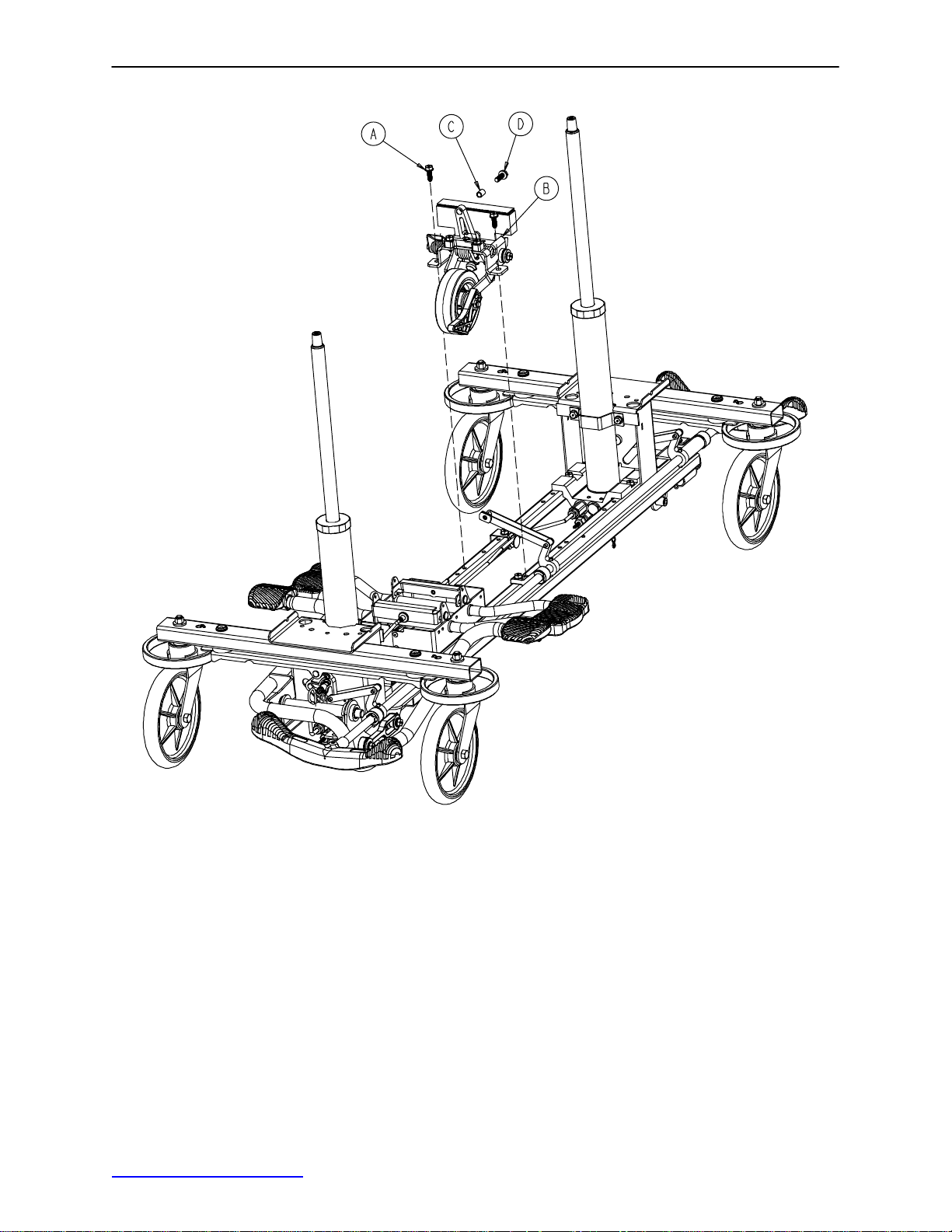
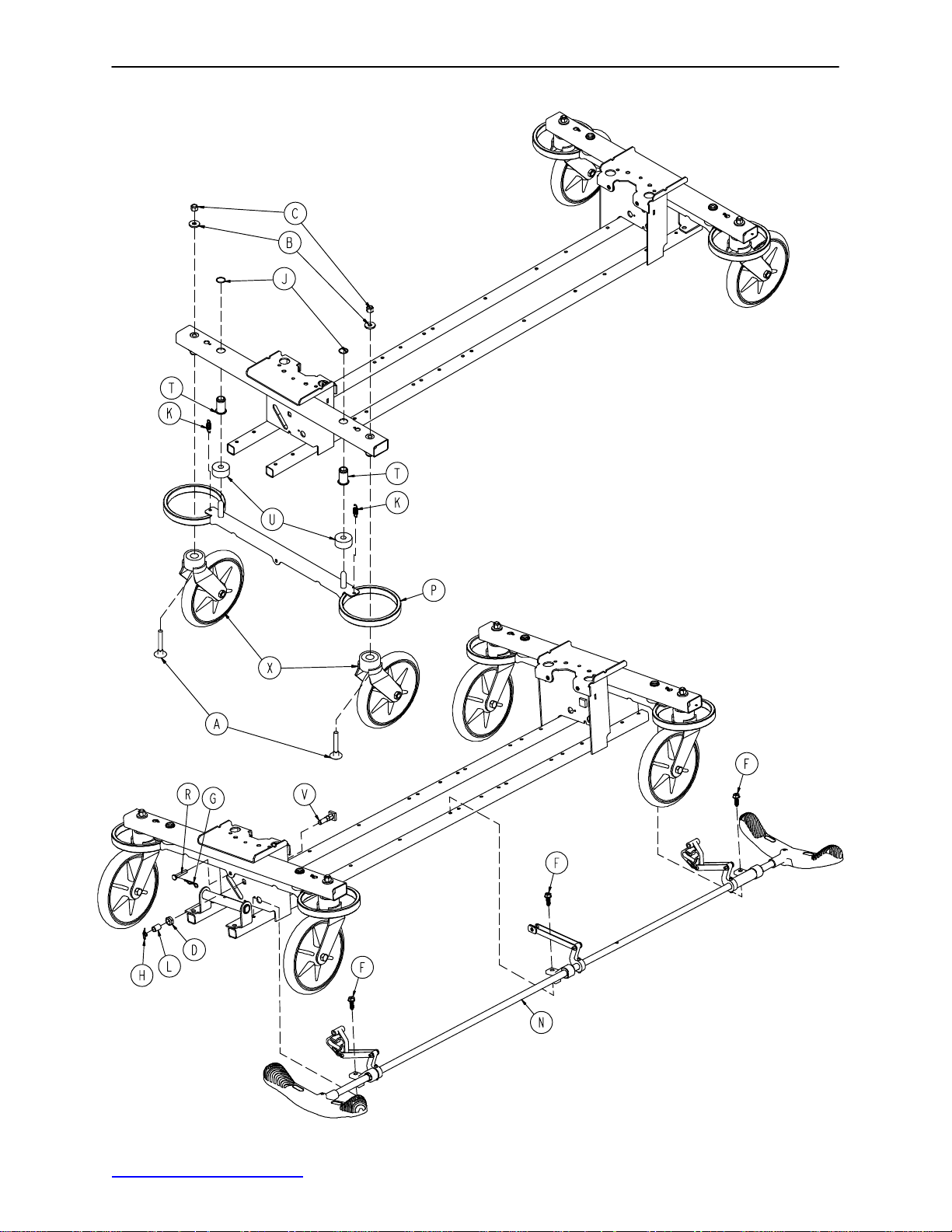
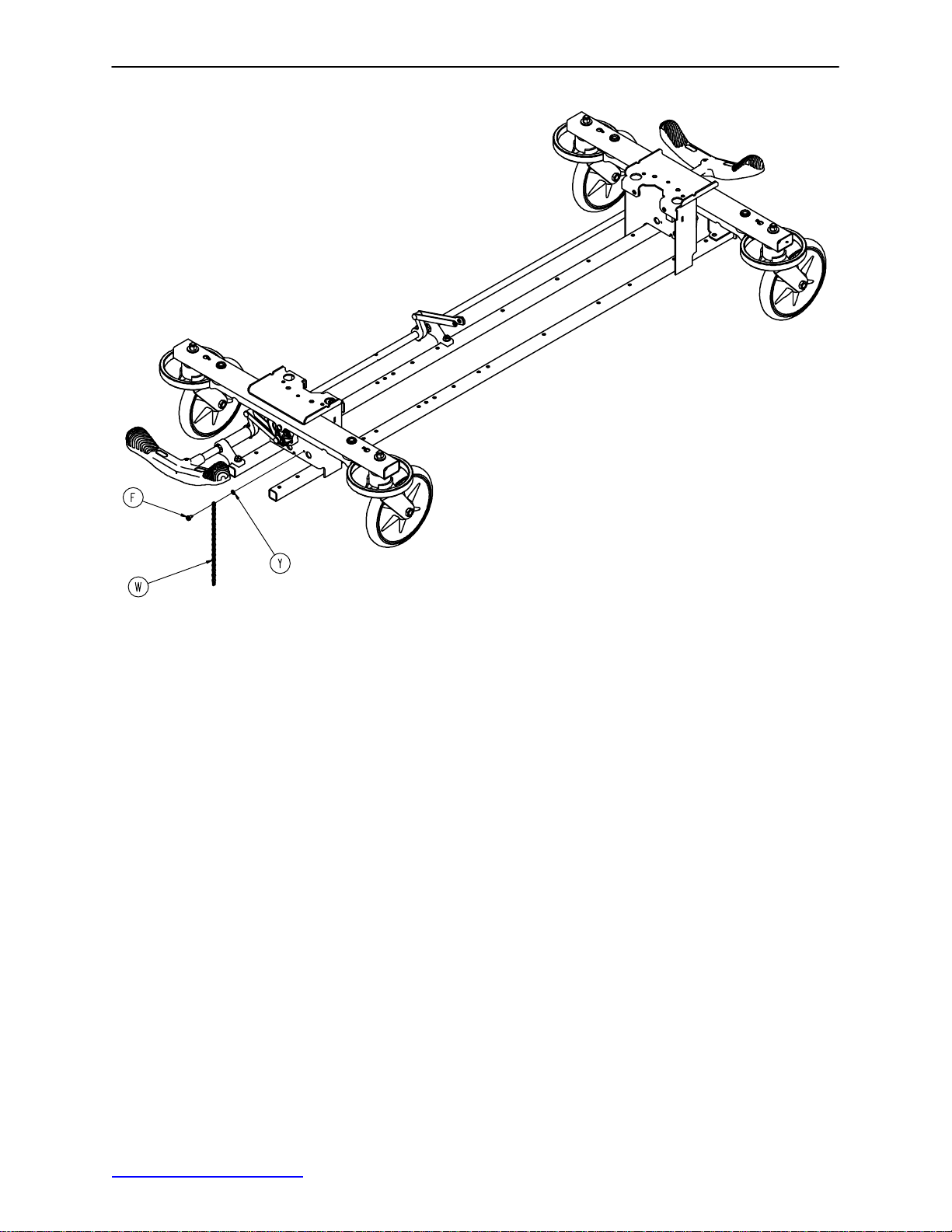
0753−006−110 Retractable Fifth Wheel Base Assembly
Item Part No. Part Name Qty.
A 0023−288−000 Hex Washer Hd. Screw 2
B(page 16) Fifth Wheel Assembly 1
C 0753−006−148 Cam Bearing 1
D 0023−305−000 Hex Hd. Cap Screw 1
Return to Table of Contents
15
Page 17
0753−006−130 Fifth Wheel Assembly
Return to Table of Contents
16
Page 18

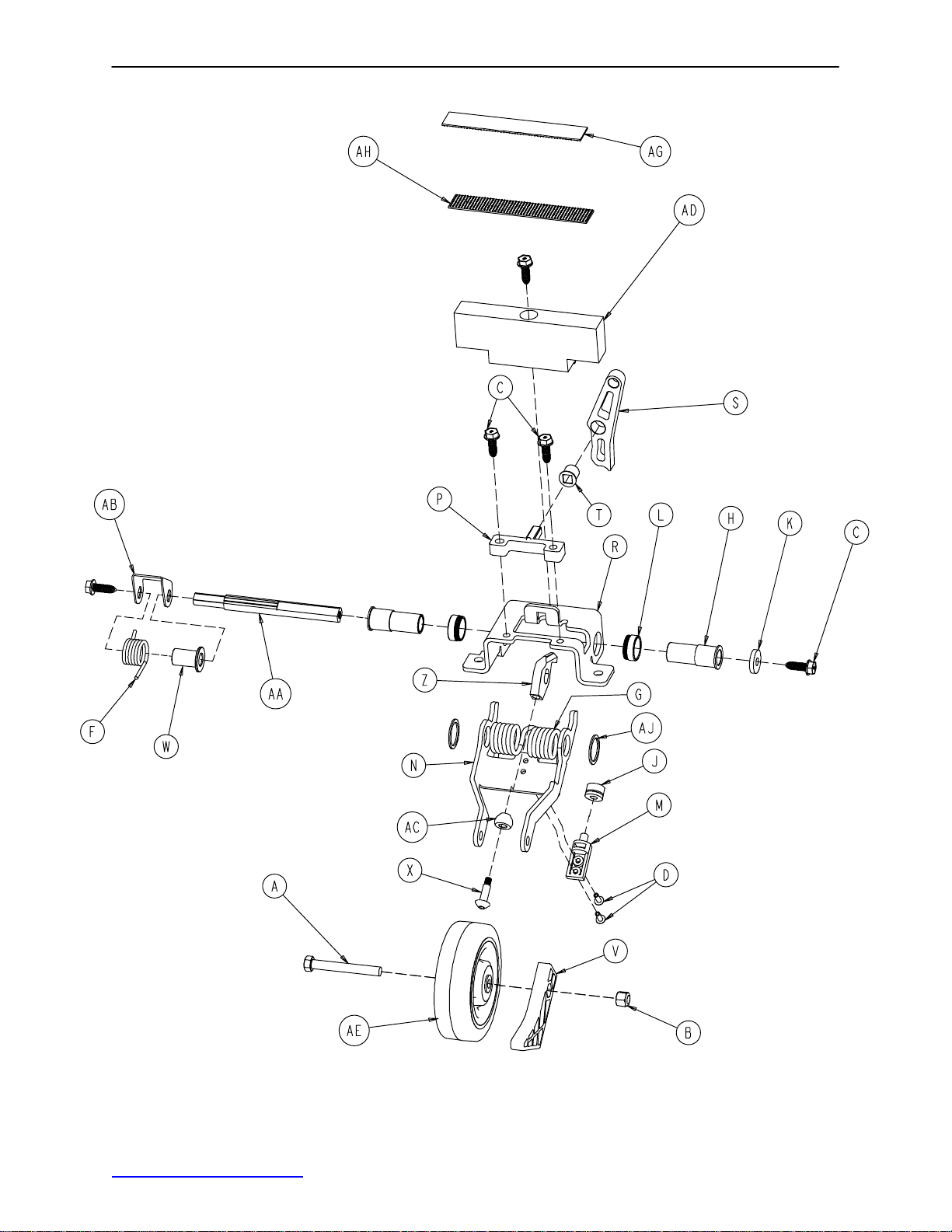
0753−006−130 Fifth Wheel Assembly
Item Part No. Part Name Qty.
A 0003−083−000 Hex Hd. Cap Screw 1
B 0016−035−000 Nylock Hex Nut 1
C 0023−288−000 Hex Washer Hd. Screw 5
D 0025−050−000 Rivet 2
F 0753−006−074 Torsion Spring 1
G 0753−006−075 Torsion Spring 1
H 0753−006−097 Drive Shaft Bearing 2
J 0753−006−106 Dampener 1
K 0753−006−108 Thrust Washer 1
L 0753−006−115 Bearing 2
M 0753−006−120 Bumper Mounting Pin 1
N 0753−006−126 Wheel Bracket 1
P 0753−006−133 Cam Pivot Block 1
R 0753−006−134 Fifth Wheel Mounting Bracket 1
S 0753−006−142 Fifth Wheel Cam 1
T 0753−006−143 Cam Bearing 1
V 0753−006−149 5th Wheel Ramp 1
W 0753−006−152 Spring Spacer 1
X 0753−006−153 Roller Stem 1
Z 0753−006−198 Drive Pin 1
AA 0753−006−223 Drive Shaft 1
AB 0753−006−227 Return Spring Hook 1
AC 0753−006−277 Roller 1
AD 0753−010−045 Hood Standoff 1
AE 1210−001−147 Wheel 1
AG 0753−006−280 Dual Lock 1
AH 0753−006−281 Dual Lock 1
AJ 0011−360−000 Washer 2
Return to Table of Contents
17
Page 19
Base Assembly w/Standard Brakes (Fifth Wheel Base)
Assembly part number
0753−003−105
(reference only)
Return to Table of Contents
18
Page 20
Base Assembly w/Standard Brakes (Fifth Wheel Base)
Item Part No. Part Name Qty.
A 0005−044−000 Step Bolt 4
B 0011−262−000 Washer 4
C 0016−035−000 Nylock Hex Nut 4
D 0016−049−000 Nylock Hex Nut 2
E 0023−288−000 Hex Washer Hd. Screw 3
F 0003−364−000 Hex Washer Hd. Screw 1
G 0027−012−000 Hitch Pin 2
H 0027−022−000 Rue Ring Cotter 2
J 0028−037−000 External Retaining Ring 4
K 0038−439−000 Extension Spring 4
L 0081−037−000 Plane Bearing 2
M 0753−001−001 Base Frame 1
N(page 20) Brake Rod Assembly 1
P 0753−003−006 Brake Ring 2
R 0753−003−066 Clevis Pin 2
T 0753−003−079 Caster Tube Brake Pin Guide 4
U 0753−003−121 Brake Cushion 4
V 0753−003−230 Bearing Pivot Support 2
W 3001−200−052 Ground Chain 1
X(page 23) Caster Assembly 4
Y 0013−018−000 External Tooth Lock Washer 1
Return to Table of Contents
19
Page 21

Brake Rod Assembly
Assembly part number 0753−003−001 (reference only)
Item Part No. Part Name Qty.
A 0026−067−000 Slotted Spring Pin 2
E 0753−003−004 Brake Rod Support 3
F(page 21) Drive Link Assembly 2
G 0753−003−014 Brake Rod 1
H 0753−003−015 Brake Rod Nyliner 3
J 0785−003−099 Butterfly “V” Pedal 2
K(page 22) Drive Link Assembly 1
M 1210−201−335 Red Brake Label 2
N 1210−201−336 Green Steer Label 2
R 0753−003−133 Retainment Spacer 1
Return to Table of Contents
20
Page 22

0753−003−010 Drive Link Assembly
Item Part No. Part Name Qty.
B 0753−003−011 Brake Rod Drive Link 1
C 0753−003−061 Brake Cam Drive Link 2
D 0753−003−098 Flat Hd. Semi−Tubular Rivet 2
E 0753−003−102 Brake Cam 1
Return to Table of Contents
21
Page 23

0753−006−135 Drive Link Assembly
Item Part No. Part Name Qty.
A 0753−003−011 Brake Rod Drive Link 1
B 0753−003−098 Semi−Tubular Rivet 1
C 0753−006−122 5th Wheel Cam Drive Link 1
D 0753−006−147 Fifth Wheel Drive Link 1
Return to Table of Contents
22
Page 24

0753−010−220 8” Caster Assembly
Item Part No. Part Name Qty.
A 0003−099−000 Hex Hd. Cap Screw 1
B 0016−060−000 Centerlock Nut 1
C 0753−003−215 Wheel 1
D 0753−010−021 Caster Horn w/Bearing 1
Return to Table of Contents
23
Page 25

Base Assembly with 4−Sided Brakes
Assembly part number 0753−003−120
(reference only)
Return to Table of Contents
24
Page 26

Base Assembly with 4−Sided Brakes
AD
Item Part No. Part Name Qty. Item Part No. Part Name Qty.
A 0005−044−000 Step Bolt 4 P 0753−003−066 Clevis Pin 2
B 0011−262−000 Washer 4 R 0753−003−079 Brake Pin Guide 4
C 0016−035−000 Nylock Hex Nut 4 S (page 27) Side Brake Rod Ass’y 1
D 0016−049−000 Nylock Hex Nut 2 T 0753−003−121 Brake Cushion 4
E 0023−288−000 Hex Washer Hd. Screw 8 V (page 26) Brake Rod Assembly 1
G 0027−012−000 Hitch Pin 2 W 0753−003−130 Bearing Pivot Support 2
H 0027−020−000 Rue Ring Cotter 1 Y (page 23) Caster Assembly 4
J 0028−037−000 External Retaining Ring 4 Z 0026−340−000 Clevis Pin 1
K 0038−439−000 Extension Spring 4 AA 0027−019−000 Rue Ring Cotter Pin 2
L 0081−272−000 Roller Bearing 2 AB 3001−200−052 Ground Chain 1
M 0753−001−001 Base Weldment 1 AC 0003−364−000 Hex Washer Hd. Screw 1
N 0753−003−006 Brake Ring Weldment 2 AD 0013−018−000 Ext. Tooth Lock Washer 1
Return to Table of Contents
25
Page 27

Brake Rod Assembly, Base with 4−Sided Brakes
Assembly part number 0753−003−125 (reference only)
Item Part No. Part Name Qty.
A 0026−067−000 Slotted Spring Pin 6
D 0753−003−004 Brake Rod Support 4
E(page 21) Drive Link Assembly 2
F 0753−003−014 Brake Rod 1
G 0753−003−015 Brake Rod Nyliner 4
H 0785−003−099 Butterfly “V” Pedal 2
J 0753−003−112 Side Control Link 1
K(page 22) Drive Link Assembly 1
M 1210−201−335 Red Brake Label 2
N 1210−201−336 Green Steer Label 2
P 0753−003−133 Retainment Spacer 1
Return to Table of Contents
26
Page 28

Side Control Brake Rod Assembly
Assembly part number 0753−003−210 (reference only)
Item Part No. Part Name Qty.
A 0026−067−000 Slotted Spring Pin 4
B 0026−340−000 Clevis Pin 1
C 0027−020−000 Rue Ring Cotter 1
D 0753−003−099 Butterfly “V” Pedal 2
E 0753−003−112 Side Control Link 1
F 0753−003−117 Rod End Link 1
G 0753−003−119 Side Control Brake Rod 1
H 0753−003−214 Shaft Support 1
J 1210−201−335 Red Brake Label 2
K 1210−201−336 Green Steer Label 2
Return to Table of Contents
27
Page 29

Base with Dual Side Hydraulics (Fifth Wheel Base)
HEAD END
Insert pump ram into keyhole
slot on both ends. Lower pump
connecting rod weldment onto
pump ram as shown
Assembly part number 0753−005−200 (reference only)
Return to Table of Contents
Insert spring hook thru slots in pump pedal
Attach other end onto jack tower as shown
28
Page 30

Base with Dual Side Hydraulics (Fifth Wheel Base)
Insert spring hook thru
hole in pump connecting
rod. Attach other hook to
return spring as shown
Return to Table of Contents
Insert spring hook onto hook
on release pedal. Insert other
hook onto pump connecting
rod as shown.
29
Page 31

Base with Dual Side Hydraulics (Fifth Wheel Base)
See Detail A
Insert head end release
rod into release valve
assembly as shown
DETAIL B
Insert foot end release
rod into release valve
assembly as shown
See Detail B
DETAIL A
Item Part No. Part Name Qty.
A 0011−023−000 Washer 2
B 0014−071−000 Washer 2
C 0023−288−000 Hex Washer Hd. Screw 7
D 0027−031−000 Hair Pin Cotter 1
E 0038−497−000 Extension Spring 3
F 0753−004−014 Head End Release Rod 1
G 0753−004−015 Foot End Release Rod 1
H(page 31) Release Pedal Assembly 1
J 0753−004−132 Release Pedal Swivel 2
K 0753−005−037 Pump Connecting Rod 1
L 0753−005−044 Pump Pedal Bushing 2
M 0753−005−074 Pivot Pin 1
N 0753−005−075 Pump Pedal Link 1
P 0753−005−087 Return Spring Hook 1
R 0753−005−088 Wear Strip 2
T 0753−005−089 Pump Ram Plug 2
U(page 32) Head End Pump Pedal Ass’y 1
V 0753−010−215 Release Rod Bracket 1
Return to Table of Contents
30
Page 32

0753−004−101 Release Pedal Assembly
Item Part No. Part Name Qty.
A 0025−079−000 Rivet 4
B 0753−004−004 Release Pedal Weldment 2
C 0753−004−029 Release Pedal Standoff 4
D 0753−004−320 Release Pedal Support 2
F 1061−201−127 Short Uni Pedal 2
Return to Table of Contents
31
Page 33

0753−005−185 Head End Pump Pedal Assembly
Item Part No. Part Name Qty.
A 0026−343−000 Groove Pin 2
B 0715−001−140 Vinyl Tube 1
C 0753−005−044 Pump Pedal Bushing 2
D 0753−005−180 Head End Pump Pedal Weldment 1
E 0753−201−126 Pump Pedal 2
Return to Table of Contents
32
Page 34

Variable Descent Jacks
Assembly part number 0753−002−180
(reference only)
Item Part No. Part Name Qty.
A 0023−288−000 Hex Washer Hd. Screw 8
B 0753−002−170 Variable Descent Jack Assembly 2
C 0753−010−007 Reservoir Clamp 2
Return to Table of Contents
33
Page 35

Jack Base Assembly, Variable Descent Jack
Assembly part number 0753−002−075 (reference only)
Item Part No. Part Name Qty.
A 0046−004−000 O−Ring 1
B 0048−021−000 CV Plug 2
C 0390−002−134 Conical Compression Spring 1
D 0715−001−341 Poppet 1
E 0753−002−003 Pump Ram Assembly 1
F 0753−002−010 Jack Base 1
G 0753−002−019 Valve Filter 1
H 0753−002−051 Plug Assembly 1
J 0753−002−052 Check Valve Assembly 1
K 0753−002−063 Standard Descent Valve Assembly 1
L 0753−002−065 Release Valve Assembly 1
Return to Table of Contents
34
Page 36

Notes
Return to Table of Contents
35
Page 37

Base Labeling Assembly
Assembly part number 0753−010−062 (reference only)
Department Label
see page 38
Specification Label
(Serial Number Location)
FOOT END
HEAD END
Item Part No. Part Name Qty.
A 0753−010−040 Base Hood 1
B 1040−010−134 Bellows 2
C 0946−201−060 Stryker Logo Label 4
Return to Table of Contents
36
Page 38

Base Labeling Assembly, 4−Sided Brakes
Assembly part number 0753−010−063 (reference only)
Department Label
see page 38
Specification Label
(Serial Number Location)
FOOT END
HEAD END
Item Part No. Part Name Qty.
A 0753−010−040 Base Hood 1
B 1040−010−134 Bellows 2
C 0946−201−060 Stryker Logo Label 4
H 0753−010−018 Brake/Steer Label, Right 1
J 0753−010−019 Brake/Steer Label, Left 1
Return to Table of Contents
37
Page 39

Base Labeling Assembly
Color
Set P/N
RED
0753−010−120
PURPLE
0753−010−121
GREEN
0753−010−122
GRAY
0753−010−123
TEAL
0753−010−124
PINK
0753−010−125
BLUE
0753−010−126
Item D Brake/
Steer, Foot End
0753−010−051 0753−010−055 0753−010−017 0753−010−054 1010−700−015
0753−010−151 0753−010−155 0753−010−170 0753−010−154 1010−700−025
0753−010−251 0753−010−255 0753−010−270 0753−010−254 1010−700−035
0753−010−351 0753−010−355 0753−010−370 0753−010−354 1010−700−045
0753−010−451 0753−010−455 0753−010−470 0753−010−454 1010−700−055
0753−010−551 0753−010−555 0753−010−570 0753−010−554 1010−700−065
0753−010−651 0753−010−655 0753−010−670 0753−010−654 1010−700−075
Item E
Lift/Lower, Left
BASE HOOD DEPARTMENT LABELS
Item F Brake/
Steer, Head End
Item G
Lift/Lower, Right
Litter
Bumper Strip
Department Label Part Number
Emergency 1010−900−215
PACU 1010−900−220
Transport 1010−900−225
Surgery 1010−900−230
Extended Stay 1010−900−235
Maternity 1010−900−240
Endoscopy 1010−900−245
Radiology 1010−900−250
Nuclear Medicine 1010−900−255
Ambulatory Surgery 1010−900−260
G.I. Lab 1010−900−265
Cath. Lab 1010−900−270
Same Day Surgery 1010−900−275
Cardio. 1010−900−280
Ultrasound 1010−900−285
NOTE
All base hood department labels are quantity of two.
Return to Table of Contents
38
Page 40

Assembly part number 0721−301−010
(reference only)
Litter Assembly
HEAD END
Siderail
Latch
Assembly
Return to Table of Contents
39
Page 41

DETAIL A
Litter Assembly
See Detail A
HEAD END
Return to Table of Contents
40
Page 42

Litter Assembly
Item Part No. Part Name Qty.
A 0003−359−000 Hex Hd. Cap Screw 8
B 0004−135−000 But. Hd. Cap Screw 4
C 0004−515−000 But. Hd. Cap Screw 14
D 0011−002−000 Washer 4
E 0011−360−000 Washer 2
F 0016−118−000 Hex Nut 10
G 0021−104−000 Set Screw 2
H 0007−074−000 Truss Hd. Machine Screw 2
J 0025−040−000 Dome Hd. Rivet 20
K 0025−079−000 Dome Hd. Rivet 24
L 0028−023−000 External Retaining Ring 2
M 0037−074−000 Hole Plug 2
N 0038−220−000 Compression Spring 2
P 0721−026−066 Pivot Screw 14
R 0721−026−068 Upright Cradle 6
T 0721−026−069 Upright Sleeve 4
U 0721−026−074 Lock Handle 2
V(page 42) Siderail Assembly, Right 1
W(page 42) Siderail Assembly, Left 1
Y 0721−031−065 Hole Plug 4
AA 0721−201−020 Litter Frame Weldment 1
AB 0753−010−036 Support Tube, Head End 1
AC 0753−010−042 Support Tube, Foot End 1
AD 0753−010−043 Jack Supt. Tube, Hd. End 2
AE 0753−010−044 Stationary Foot Section Skin 1
AF 0938−001−401 Collar 2
AG 1001−040−012 Foot Board Receptacle 2
AH 1001−201−029 Nylon Insert 2
AJ 1001−401−030 Trend Support 2
AK 1010−026−069 Lock Support 2
AL 1010−026−080 Lock Housing, Left 1
AM 1010−026−081 Lock Housing, Right 1
AN 1010−201−027 Bumper Channel 2
AP 1210−800−008 Patent Label 1
AR 1010−026−103 Spring Retainer 2
AT 0023−283−000 Pan Hd. Screw 8
AU 0037−059−000 Hole Plug 2
AV 1010−201−238 Corner Cover, Slot 2
AW 1010−201−239 Corner Cover, Hole 2
AY 0016−117−000 Hex Lock Nut 4
BA 0014−021−000 Washer 12
BB 0926−400−142 Bumper 4
BC 0004−330−000 Soc. Hd. Cap Screw 4
Return to Table of Contents
41
Page 43

Siderail Assembly, Right & Left
Assembly part numbers − (reference only)
0721−026−096 (Right)
0721−026−097 (Left)
J
(Left Side Shown for 0721−026−097)
Item Part No. Part Name Qty.
A 1010−026−015 Top Rail 1
B 1010−026−083 Upright 4
C 1010−026−084 Upright, Bent 1
D 1010−026−082 Spacer 6
E 0025−106−000 Semi−Tubular Rivet 6
F 1010−026−010 Round Hole Plug 4
H 1010−026−085 Upright, Latch 1
J 1010−026−012 Bent Spindle Stop 1
Return to Table of Contents
42
Page 44

Fowler to Frame Assembly
Assembly part number 0721−231−110 (reference only)
HEAD END
Item Part No. Part Name Qty.
A 0004−182−000 Hex Soc. But. Hd. Cap Screw 2
B 0004−183−000 Hex Soc. But. Hd. Cap Screw 2
C 0011−179−000 Washer 2
D 0014−021−000 Washer 8
E 0015−060−000 Hex Jam Nut 2
F 0016−116−000 Hex Nut 2
H 0016−117−000 Hex Nut 2
J 0023−256−000 Self−Tapping Screw 2
K 0025−122−000 Blind Rivet 9
L(page 44) 26” Pneumatic Fowler Assembly 1
(page 46) 30” Pneumatic Fowler Assembly
M 1010−031−078 Gas Cylinder 2
N 1211−031−031 Pneumatic Fowler Rest 2
Return to Table of Contents
43
Page 45

Pneumatic Fowler Assembly
A
0
ssembly part number
721−231−120 (reference only)
Item Part No. Part Name Qty.
A 0004−135−000 But Hd. Cap Screw 6
B 0004−161−000 Hex Soc. But. Hd. Cap Screw 2
C 0007−071−000 Truss Hd. Mach. Screw 4
D 0015−037−000 Jam Nut 2
E 0015−050−000 Hex Nut 2
F 0016−118−000 Stover Lock Nut 12
H 0021−125−000 Set Screw 2
J 0021−126−000 Set Screw 2
K 0721−231−012 Fowler Skin 1
L 0721−231−013 Fowler Tube 1
M 0721−231−118 Trip Bar Assembly 1
N 1001−001−036 Hole Plug 2
P(page 45) Outer Housing Ass’y, Right 1
R(page 45) Outer Housing Ass’y, Left 1
Return to Table of Contents
44
Page 46

Pneumatic Fowler Outer Housing Assembly
Assembly part number 1210−031−106 (Right)
Item Part No. Part Name Qty.
A 0025−144−000 Semi−Tubular Rivet 1
B 1210−031−103 Pivot Tab 1
C 1210−031−104 Outer Housing, Right 1
Assembly part number 1210−031−107 (Left)
Item Part No. Part Name Qty.
A 0025−144−000 Semi−Tubular Rivet 1
B 1210−031−103 Pivot Tab 1
C 1210−031−105 Outer Housing, Left 1
Return to Table of Contents
45
Page 47

0721−600−010 Optional Foot End Push Handles
Item Part No. Part Name Qty.
A 0003−355−000 Hex Hd. Cap Screw 2
B 0003−356−000 Hex Hd. Cap Screw 4
D 0016−118−000 Stover Hex Lock Nut 6
E 0023−283−000 Phillips Hd. Tapping Screw 4
F 0026−114−000 Slotted Spring Pin 2
G 0037−059−000 Hole Plug 1
H 1010−201−236 Corner Cover, Hole/Slot 1
J 1010−201−237 Corner Cover, Hole/Hole 1
K 1010−254−004 Handle Socket, Left 1
L 1010−254−006 Handle Socket, Right 1
M (page 48) Push Handle Assembly 2
Return to Table of Contents
46
Page 48

0721−600−020 Optional Head End Push Handles
Item Part No. Part Name Qty.
A 1211−351−010 Push Handle Assembly 2
B 1010−254−004 Handle Socket, Left 1
C 1010−254−006 Handle Socket, Right 1
D 1010−201−237 Corner Cover H.E.L. 1
E 1010−201−236 Corner Cover H.E.R. 1
F 0003−355−000 Hex Head Cap Screw 2
G 0003−356−000 Hex Head Cap Screw 2
H 0003−357−000 Hex Head Screw 2
J 0026−114−000 Spring Pin 2
K 0023−283−000 Self−Tapping Screw 4
L 0016−118−000 Hex Nut Nylok 6
Return to Table of Contents
47
Page 49

1211−351−010 Push Handle Assembly
Item Part No. Part Name Qty.
A 1010−354−024 Stop Link 1
B 1211−151−018 Sleeve Assembly 1
C 0026−118−000 Roll Pin 1
Return to Table of Contents
48
Page 50

0390−025−022 Standard, Removable IV Pole Assembly
Item Part No. Part Name Qty.
A 0024−023−000 Plastic Knob 1
B 0390−003−053 Double IV Ass’y 1
C 0393−003−043 Tube Assembly 1
D 0004−496−000 Soc. Hd. Cap Screw 1
Return to Table of Contents
49
Page 51

721−400−001 Optional 2−Stage I.V. Assembly
Assembly part number 0721−280−000 & 0721−281−000
(reference only)
HEAD END
FOOT END
Item Part No. Part Name Qty
A(page 51) I.V. Pole Assembly 1
B 1001−259−103 I.V. Pivot 1
C 0016−118−000 Fiberlock Nut 3
E 0004−452−000 But. Hd. Cap Screw 1
F 0003−356−000 Hex Hd. Cap Screw 3
G 0016−116−000 Flexlock Nut 1
J 1001−259−042 I.V. Plug 1
Return to Table of Contents
50
Page 52

1211−210−010 Optional 2−Stage I.V. Pole Assembly
Item Part No. Part Name Qty.
A 0008−031−000 Soc. Hd. Cap Screw 1
B 0052−017−000 Washer 2
C 0926−400−162 Spacer 1
D 1211−210−029 2nd Stage Assembly 1
E 1001−359−013 Dampener 1
F 1001−159−028 Base Tube 1
G 1010−059−016 I.V. Hook 2
H(page 52) I.V. Pole Latch 1
J 1001−359−112 Pivot 1
Return to Table of Contents
51
Page 53

1211−210−026 I.V. Pole Latch Assembly
Item Part No. Part Name Qty.
A 0028−167−000 Retaining Ring 1
B 0031−004−000 Steel Ball 2
C 0038−392−000 Crest−to−Crest Spring 1
D 1211−091−034 Release Label 1
E 1211−110−018 I.V. Latch Seal 1
F 1211−110−020 Washer 2
G 1211−110−021 I.V. Latch Locking Pin 2
H 1211−110−022 I.V. Latch Guide 1
J 1211−110−024 I.V. Latch O.D. Housing 1
K 1211−110−035 Washer 1
L 1211−110−036 Self−Tapping Screw 2
M 1211−210−023 I.V. Latch I.D. Housing 1
Return to Table of Contents
52
Page 54

0721−061−000 Optional 3−Stage I.V. Assembly, Head
0721−062−000 Optional 3−Stage I.V. Assembly, Foot
FOOT END
HEAD END
Item Part No. Part Name Qty.
A(page 54) I.V. Pole Assembly 1
B 1001−259−103 I.V. Pivot 1
C 0016−118−000 Fiberlock Nut 3
E 0004−452−000 But. Hd. Cap Screw 1
F 0003−356−000 Hex Hd. Cap Screw 3
G 0016−116−000 Flexlock Nut 1
H 1001−259−042 Plug 1
Return to Table of Contents
53
Page 55

1211−211−010 Optional 3−Stage I.V. Pole Assembly
Item Part No. Part Name Qty.
A 0007−004−000 Truss Hd. Machine Screw 1
C 0026−076−000 Roll Pin 1
D 0052−017−000 Spacer 2
E 1211−210−031 2nd Stage Assembly 1
F 0926−400−162 Spacer 1
G(page 55) 3rd Stage Assembly 1
H 1001−161−023 Base Tube 1
J 1010−059−016 I.V. Hook 2
K 1010−061−014 Collar 1
L(page 52) I.V. Pole Latch 1
M 1211−110−016 Threaded Adaptor 1
N 1001−359−013 Dampener 1
P 1001−359−014 Dampener 1
R 1001−359−112 Pivot 1
Return to Table of Contents
54
Page 56

3−Stage I.V. Pole 3rd Stage Assembly
Assembly part number 1211−110−032
(reference only)
NOTE
Item F, part number 1010−061−018 is left hand thread.
When removing it, turn clockwise to loosen it.
Item Part No. Part Name Qty.
A 0031−021−000 Ball 6
B 0038−303−000 Compression Spring 1
C 1010−061−013 Ball Retainer 1
D 1010−061−016 Retaining Shaft 1
E 1010−061−017 Thumb Knob 1
F 1010−061−018 Hand Guard 1
G 1211−110−117 Nut 1
H 1211−110−033 3rd Extension Rod 1
Return to Table of Contents
55
Page 57

0785−045−200 Optional Defibrillator Tray Assembly
Strap Securing Detail
Item Part No. Part Name Qty. Item Part No. Part Name Qty.
A 0002−0044−000 Machine Screw 2 G 0785−045−403 Weight Capacity Label 1
B 0025−055−000 Rivet 4 H 0785−045−204 Tray Support 1
C 0029−008−000 Dual Lock 6 J 0785−045−207 Tray 1
D 0029−010−000 Dual Lock 6 K 0785−045−208 Bayonet 2
E 0785−045−201 Defib Tray Label 1 L 0785−045−210 Defib Tray Frame Wldmt 1
F 0785−045−402 Push/Pull Label 1 M 1010−050−021 Long Strap 1
Return to Table of Contents
56
Page 58

0785−045−400 Foot Extension/Defibrillator Tray Ass’y
Item Part No. Part Name Qty. Item Part No. Part Name Qty.
A 0004−215−000 Button Head Cap Screw 4 M 0785−045−405 Cushion 1
B 0008−049−000 Shoulder Bolt 4 N 0785−045−410 Base Mtg. Weldment 1
C 0014−020−000 Washer 4 P 0785−045−420 Frame Pivot Weldment 1
D 0014−120−000 Washer 4 R 0785−045−430 Tray Assembly 1
E 0016−028−000 Hex Nut 4 T 0785−045−450 Knob 2
F 0037−052−000 Rubber Bumper 2 U 1010−050−021 Long Strap 1
G 0038−133−000 Spring 2 V 1010−050−242 Pin Lock 1
H 0052−017−000 Spacer 4 W 1010−050−250 Lock Adjuster 1
J 0785−045−402 “Push/Pull” Label 2 X 10¹⁰−050−248 Lower Pin Lock 1
K 0785−045−403 Weight Capacity Label 1 Y 0721−031−065 Hole Plug 2
L 0785−045−401 Foot Extender/Defib Tray
Label 1
Return to Table of Contents
57
Page 59

0785−045−500 Foot Board/Chartholder Assembly
Item Part No. Part Name Qty. Item Part No. Part Name Qty.
A 0785−045−402 Push/Pull Label 1 E 0785−045−513 Front Footboard 1
B 0785−045−501 Footboard Label 1 F 0785−045−514 Small Standoff 2
C 0785−045−511 Chart Holder Thermoform 1 G 0785−045−515 Large Standoff 2
D 0785−045−512 Footboard Back 1 H 0946−029−010 Support 1
1020−130−000 Upright Oxygen Bottle Holder Ass’y
Item Part No. Part Name Qty.
A 0027−030−000 Hair Pin Cotter 1
B 1020−030−111 Upright Bottle Holder 1
C 1020−030−017 O2 Bottle Holder Label 1
Return to Table of Contents
58
Page 60

Optional O2 Bottle Retainer Assembly
Assembly part number 1040−710−095 (reference only)
Base Hood
Item Part No. Part Name Qty.
A 1040−010−091 Bottle Retainer 1
B 1040−010−092 Scrulok Fastener 4
Return to Table of Contents
59
Page 61

Mattresses and Siderail Pads
Mattress, 3” Thick x 24” Wide, Standard part # 1059−324−140. . . . . . . . . . . . . . . . . . . . . . . . . . . . .
Mattress, 4” Thick x 24” Wide, Standard part # 1059−424−140. . . . . . . . . . . . . . . . . . . . . . . . . . . . .
Mattress, 3” Thick x 26” Wide, Standard part # 1059−326−140. . . . . . . . . . . . . . . . . . . . . . . . . . . . .
Mattress, 4” Thick x 26” Wide, Standard part # 1059−426−140. . . . . . . . . . . . . . . . . . . . . . . . . . . . .
Mattress, 3” Thick x 24” Wide, Enhanced Comfort part # 0721−248−106. . . . . . . . . . . . . . . . . . . .
Mattress, 4” Thick x 24” Wide, Enhanced Comfort part # 0721−247−106. . . . . . . . . . . . . . . . . . . .
Mattress, 3” Thick x 26” Wide, Enhanced Comfort part # 1001−048−106. . . . . . . . . . . . . . . . . . . .
Mattress, 4” Thick x 26” Wide, Enhanced Comfort part # 1001−047−106. . . . . . . . . . . . . . . . . . . .
Mattress, 26” Wide, Echo part # 1059−426−010. . . . . . . . . . . . . . . . . . . . . . . . . . . . . . . . . . . . . . . . .
Return to Table of Contents
60
Page 62

Mattresses and Siderail Pads
Siderail Pad Set part # 1010−052−000. . . . . . . . . . . . . . . . . . . . . . . . . . . . . . . . . . . . . . . . . . . . . . . . . .
Return to Table of Contents
61
Page 63

Warranty
Limited Warranty:
Stryker Medical Division, a division of Stryker Corporation, warrants to the original purchaser that its products
should be free from defects in material and workmanship for a period of one (1) year after date of delivery.
Stryker’s obligation under this warranty is expressly limited to supplying replacement parts and labor for, or
replacing, at its option, any product which is, in the sole discretion of Stryker, found to be defective. If requested by Stryker, products or parts for which a warranty claim is made shall be returned prepaid to Stryker’s
factory. Any improper use or any alteration or repair by others in such manner as in Stryker’s judgement affects the product materially and adversely shall void this warranty. Any repair of Stryker products using parts
not provided or authorized by Stryker shall void this warranty. No employee or representative of Stryker is
authorized to change this warranty in any way.
Stryker Medical st r etcher products are designed for a 10 year expected service life under normal use, conditions, and with appropriate periodic maintenance as described in the maintenance manual for each device.
Stryker warrants to the original purchaser that the welds on its stretcher products will be free from structural
defects for the expected 10 year life of the stretcher product as long as the original purchaser owns the product.
This statement constitutes Stryker’s entire warranty with respect to the aforesaid equipment. STRYKER
MAKES NO OTHER WARRANTY OR REPRESENTATION, EITHER EXPRESSED OR IMPLIED, EXCEPT
AS SET FORTH HEREIN. THERE IS NO WARRANTY OF MERCHANTABILITY AND THERE ARE NO
WARRANTIES OF FITNESS FOR ANY PARTICULAR PURPOSE. IN NO EVENT SHALL STRYKER BE
LIABLE HEREUNDER FOR INCIDENTAL OR CONSEQUENTIAL DAMAGES ARISING FROM OR IN ANY
MANNER RELATED TO SALES OR USE OF ANY SUCH EQUIPMENT.
To Obtain Parts and Service:
Stryker products are supported by a nationwide network of dedicated Stryker Field Service Representatives.
These representatives are factory trained, available locally, and carry a substantial spare parts inventory to
minimize repair time. Simply call your local representative, or call Stryker Customer Service at (800)
327−0770.
Service Contract Coverage:
Stryker has developed a comprehensive program of service contract options designed to keep your equipment operating at peak performance at the same time it eliminates unexpected costs. We recommend that
these programs be activated before the expiration of the new product warranty to eliminate the potential of
additional equipment upgrade charges.
A SERVICE CONTRACT HELPS TO:
Ensure equipment reliability
Stabilize maintenance budgets
Diminish downtime
Establish documentation for JCAHO
Increase product life
Return to Table of Contents
Enhance trade−in value
Address risk management and safety
62
Page 64

Warranty
Stryker offers the following service contract programs:
SPECIFICATIONS GOLD SILVER PM* ONLY
Annually scheduled preventative maintenance X X
All parts,** labor, and travel X X
Unlimited emergency service calls X X
Priority one contact; two hour phone response X X X
Most repairs will be completed within 3 business days X X
JCAHO documentation X X X
On−site log book w/ preventative maintenance & emergency service records X
Factory−trained Stryker Service Technicians X X X
Stryker authorized parts X X X
End of year summary X
Stryker will perform all service during regular business hours (9−5) X X X
* Replacement parts and labor for products under PM contract will be discounted.
** Does not include any disposable items, I.V. poles (except for Stryker HD permanent poles), mattresses, or damage re-
sulting from abuse.
Stryker Medical also offers personalized service contracts.
Pricing is determined by age, location, model and condition of product.
For more information on our service contracts,
please call your local representative or call (800) 327−0770 (option #2).
Return Authorization:
Merchandise cannot be returned without approval from the Stryker Customer Service Department. An authorization number will be provided which must be printed on the returned merchandise. Stryker reserves the
right to charge shipping and restocking fees on returned items.
SPECIAL, MODIFIED, OR DISCONTINUED ITEMS NOT SUBJECT TO RETURN.
Damaged Merchandise:
ICC Regulations require that claims for damaged merchandise must be made with the carrier within fifteen
(15) days of receipt of merchandise. DO NOT ACCEPT DAMAGED SHIPMENTS UNLESS SUCH DAMAGE
IS NOTED ON THE DELIVERY RECEIPT AT THE TIME OF RECEIPT. Upon prompt notification, Stryker
will file a freight claim with the appropriate carrier for damages incurred. Claim will be limited in amount to
the actual replacement cost. In the event that this information is not received by Stryker within the fifteen
(15) day period following the delivery of the merchandise, or the damage was not noted on the delivery receipt
at the time of receipt, the customer will be responsible for payment of the original invoice in full.
Claims for any short shipment must be made within thirty (30) days of invoice.
International Warranty Clause:
This warranty reflects U.S. domestic policy. Warranty outside the U.S. may vary by country . Please contact
your local Stryker Medical representative for additional information.
Return to Table of Contents
63
Page 65

European Representative
Stryker EMEA RA/QA Director
Stryker France
ZAC Satolas Green Pusignan
Av. De Satolas Green
69881 MEYZIEU Cedex
France
3800 E. Centre Ave., Portage, MI 49002
(800) 327−0770
www.stryker.com
JH 10/06 0735−009−002 REV D
 Loading...