

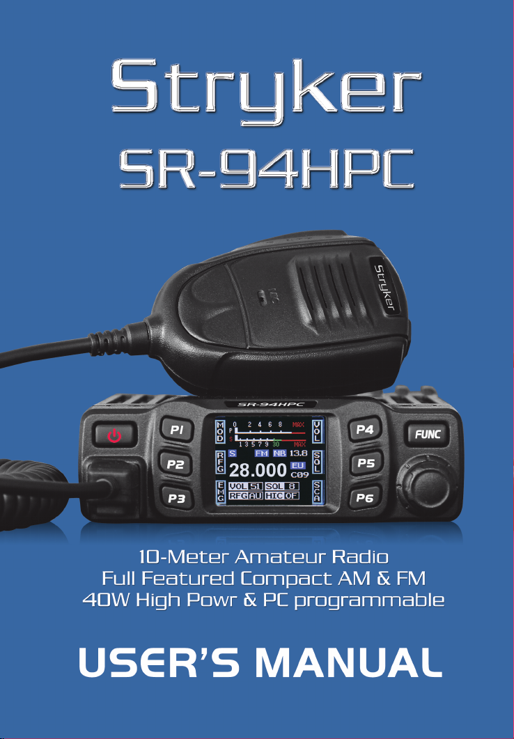
Page 1

www.strykerradios.com
A1.0 161122
Page 2
Page 3

INTRODUCTION
Congratulations on your purchase of a Stryker 10 meter mobile amateur
transceiver .Your Stryker is designed to provide years of enjoyment and
trouble-free service. There are many features and functions designed into
this transceiver. To ensure that your investment is enjoyed to its fullest
extent, please take a few moments and thoroughly read this manual.
LIMITED WARRANTY
Stryker Amateur Radio warrants this product to be free of defects for a
period of three (3) year from the original date of purchase. You must
activate your warranty online at http://strykerradios.com/registration-
form/ This warranty is non-transferable. This limited warranty is subject
to repair or replacement of defective components only. This warranty is
void if the radio has been tampered with or misused. If your Stryker
Radios needs repair any time during the (1) year warranty period please
visit repairs.strykerradios.com to obtain an RMA Number. If you do
need service after your warranty has expired you can still sen your radio
to us for repair. Our rates are very reasonable and you can rest assured
that your radio will be fixed correctly.
IMPORTANT: RETAIN YOUR SALES RECEIPT
You will need to include a copy of your original sales receipt along with
your radio when sending it in for warranty repair.
Improper Radio Adjustments
Service by unqualified technicians could result in damage to your radio.
Never allow anyone to disable your radio’s modulation limiting
circuitry. We have designed your radio for optimal performance and
durability. Disabling this circuitry could damage your radio and
potentially void your factory warranty!
For further service information please visit www.StrykerRadios.com.
Page 4

WARNING
In order to comply with RF exposure requirements for mobile
transmitting devices, a minimum distance of 20cm must be
maintained between the antenna and all persons.
Page 5

CONTENTS
FUNCTIONS AND CHARACTERS ................................................................... 1
STANDARD ACCESSORIES ............................................................................ 2
OPTIONAL ACCESSORIES ............................................................................. 2
INSTALLATION .................................................................................................2
Microphone Connection ............................................................................... 2
Antenna Connection .................................................................................... 3
Power Connection ....................................................................................... 3
Fuse Replacement ....................................................................................... 3
Intall Microphone Hanger ............................................................................. 4
Intall External Speaker ................................................................................. 4
GETTING ACQUAINTED .................................................................................. 5
Front Panel .................................................................................................. 5
Rear Panel ................................................................................................... 5
Microphone .................................................................................................. 6
KEY FUNCTION OPERATION ......................................................................... 6
BACKGROUND FUNCTION MENU OPERATION ......................................... 10
PUBLIC DATA FUNCTION MENU OPERATION ........................................... 14
CHANNEL FUNCTION MENU OPERATION .................................................. 15
DTMF ENCODE SETTING .............................................................................. 16
SELF –DEFINE KEY SETTING ...................................................................... 18
SPECIFICATIONS ...........................................................................................19
Page 6

1. FUNCTIONS & FEATURES
● FTF LCD display
● 12/24V voltage(4W version only)
● Full alloy body for heat radiation
● Programmable keypad
● CTCSS/DCS (optional)
● Wireless microphone control(optional)
● Cell-phone APP control (optional)
● AM/FM multi band
● Flexible menu and programming software
● DTMF
● SQ, ASQ
● SQ, ASQ open/close value setting
● RF Gain
● Scan
● Dual watch
● Programmable RB
● CH9/19
● NB
● HI-CUT
● Voltage protection
● 8 memory channel
● TOT
● Backlight control
● Automatic power on
● Keypad lock
1
Page 7
2
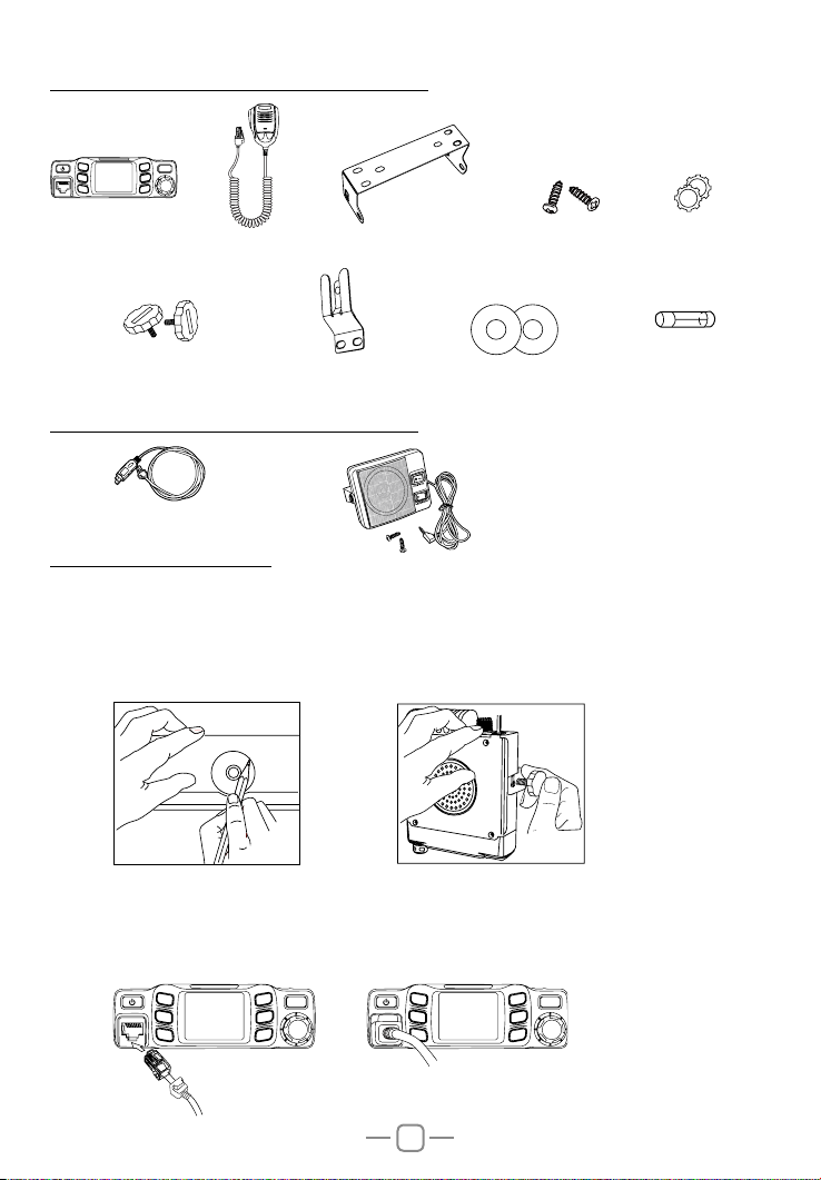
2. STANDARD ACCESSORIES
P1
P4
P2
MIC
P3
FUNC
P5
P6
Radio
Adjusting screws
Microphone
Microphone Hanger
Install bracket
non-slip mat
3. OPTIONAL ACCESSORIES
PC cable
8 ohm speaker
4. INSTALLATION
Choose a idea location to install the radio.
1. Mark the location for screws by intall racket.
2. Fix the bracket by screws.
3. Fix radio base into install bracket and lock by adjusting knobs.
Screws
Pads
Fuse(5A 250V)
4.01 Microphone connection
1. Plug microphone connector into jack.
2. Pull on the dustproof cover for microphone connector.
P1
P2
MIC
P3
P4
FUNC
P5
P6
P1
P2
MIC
P3
P4
FUNC
P5
P6
Page 8
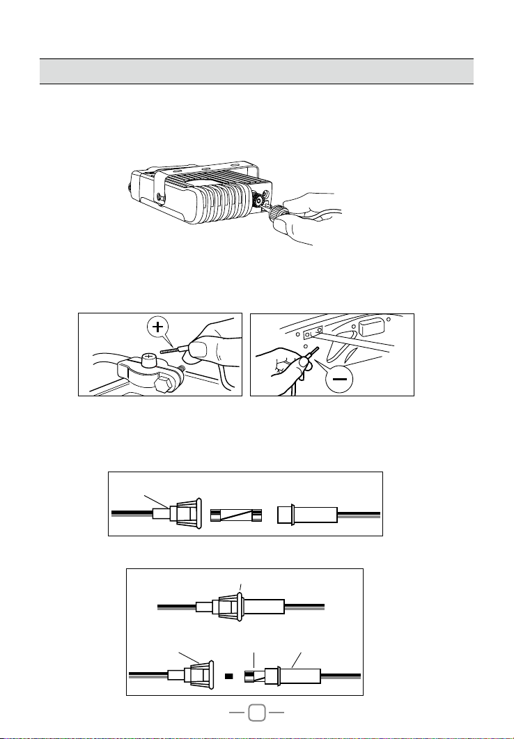
4.02 Antenna connection
Note: Never press PTT before install the antenna, it might burn the final transistor.
1. Screw on the antenna into antenna jack.
2. To make full use of this radio, it is necessary to locate the antenna in a well
grounded place, and well adjust the SWR.
* Please enquiry the local dealer for choosing and intallation of suitable antenna.
P
S
T
X
E
T
N
A
4.03 Power connection
This radio requires a 13.2V DC power supply (14.2V DC is ideal)
Connect the red wire to the positive terminal of the battery, and the black wire to the
negative terminal of the battery.
4.04 Fuse replacement
This radio adopt 5A, 250V fuse
1. Open the fuse holder
, 250V FUSE
IN-LINE
FUSE HOLDER
5A
2. Replace the fuse and screw on the holder.
IN-LINE
FUSE HOLDER
IN-LINE
FUSE HOLDER
FUSE
3
IN-LINE
FUSE HOLDER
Page 9

4
4.05 Intall Microphone hanger
1. Choose idea location and mark for screw point.
2. Fix the hanger by the srews in accessory list.
4.06 Intall external speaker
This radio adopt 4-8 ohm, 4W external speaker.
1. Install the external speaker in idea location.
2. Plug in the seaker connector into jack.
P
S
T
X
E
T
N
A
Page 10
5. GETTING ACQUAINTED
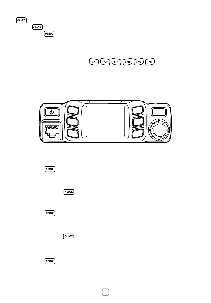
5.01 Front Panel
2
1
3 6
MIC
P1
P2
P4
P5
FUNC
9
P3
P6
4
NO. Key Functions
1
2
3
4
5
6
7 Programmable Key 6 (Default: Power)
8 Function Menu key
9 MIC Microphone Jack
10 Channel Switch/Push key/ Key lock
Power On/Off/Mute
Programmable Key 1 (Default: Mode AM or FM)
Programmable Key 2 (Default: RF Gain)
Programmable Key 3 (Default: EMG 9 & 19)
Programmable Key 4 (Default: Volume)
Programmable Key 5 (Default: Squelch)
5.02 Rear Panel
5
8
10
7
NO. Functions
10 External Speaker Jack
11 Antenna Jack
ANT EXT SP
5
Page 11

5.03 Microphone
Channel Down Channel UP
PTT
Connector
6. KEY FUNCTION OPERATION
1. Short press
2. Power off radio: hold
3. when radio is powered on, short press
AUDIO:MT, the radio volume will mute.
short press
key, the radio emit a prompt and LCD display on.
key, until LCD display off.
key, LCD displays AUDIO: Esc, radio will recover last volume level.
Mic
Microphone cable
key, LCD displays
Channel switch~PUSH
1. Turn channel switch anti-clockwise to move to down channel, turn it clockwise to up
channel.
2. Fast channel adjust: short press [PUSH] key to adjust channel by 10 steps each push.
3. Key lock: Hold [PUSH] key, LCD displays Key Lock, All keys except [PTT] key are
locked.
Hold [PUSH] key again to unlock the key.
6
Page 12
7
1.Short to switch between 3 groups of self dene funciton keys.
2.Long press
to enter background function menu.
[P1]~[P6]
This radio has 6 self define keys , , , , , ,each key can set 3
functions.
P1~P3 matching the 3 function display in left side LCD, P4~P6 matching the functions
display in the right side of the LCD; Please refer to KEY MENU operation to allocate key
functions.
MIC
P1
P2
P3
P4
P5
P6
FUNC
MOD: AM/FM mode
1.Short press key to choose programmed function group.
2.Short press the programmable key which allocated as MOD function, the LCD displays
MOD:XX.
3.Short press it again or turn channel switch to switch between FM→AM.
4.Press [PUSH] key or key to store setting and exit.
RFG: Adjust RF gain
1.Short press key to choose programmed function group.
2.Short press the programmable key which allocated as RFG function, LCD displays
RFG: XX.
3.Short press it again or turn channel switch to adjust RF gain level.
4.Press [PUSH] key or
key to store setting and exit.
Note: When RFG is ON, LCD will display the level accordingly.
EMG: CH9/CH19
1.Short press key to choose programmed function group..
2.Short press the programmable key which allocated as EMG function, first press is
choose CH9.
3.Short press it again, will choose CH19.
4.Short press it third time, will return to last normal channel.
Page 13

8
VOL: Volume level control
1.Short press key to choose programmed function group.
2.Short press the programmable key which allocated as VOL function, LCD displays VOL:
XX.
3.Turn channel switch to adjust volume level.
4.Press [PUSH] key or key to store setting and exit.
SQL~ASQ:
Short press: Squelch level control
1.Short press key to choose programmed function group..
2.Short press the programmable key which allocated as SQL function, LCD displays SQ:
XX.
3.Turn channel switch to adjust S level.
4.Press [PUSH] key or key to store setting and exit.
Long press: ASQ level control
1.Short press key to choose programmed function group.
2.Long press the programmable key which allocated as ASQ function, LCD displays ASQ:
XX.
3.urn channel switch to adjust ASQ level.
4.Press [PUSH] key or key to store setting and exit.
5.Long press the programmable key again to turn on SQL function.
DSP: Channel/Frequency display mode.
1.Short press key to choose programmed function group.
2.Short press the programmable key which allocated as DSP function, LCD displays
DSP:XX.
3.Short press it again or turn channel switch to switch between CH→FRQ.
4.Press [PUSH] key or key to store setting and exit.
SCAN~ SCAN ADD:
Short press: Turn on scan function
1.Short press key to choose programmed function group..
2.Short press the programmable key which allocated as SCA function, LCD displays“1S1”.
3.During scanning, turn channel switch to change scan direction.
4.Press [PUSH] key or key exit scan.
Long press: add/delete scan list
In channel mode, Long press the programmable key which allocated as SCA function to
add or delete channel from scan list.
1. When the LCD displays“S”means current channel is in scan list.
2. When the “S”disappear, means current channel is deleted from scan list.
Note: this function is same as the channel menu 2 control
Page 14
9
MEM~STORE:
Short press: use memory channel
1.Short press key to choose programmed function group.
2.Short press the programmable key which allocated as MEM function to enter memory
channel, turn channel switch to choose memory channels.
3.Short press it again to store setting and exit.
Long press: Memory channel store position
1.Choose a channel
2.Short press key to choose programmed function group.
3.Long press the programmable key which allocated as MEM function , the LCD displays
memory channel number, turn channel switch to choose channel number(CH-01~CH-08),
Long press [MEM] key until LCD displays the stored channel.
1.when the channel number is not flash, means the channel already stored into
»
memory channel.
2.when the channel number is flash, means the channel is not into memory
»
channel.
DW: Dual-watch control
1.Choose rst dual-watch channel,,and select working mode(AM or FM)
2.Short press key to choose programmed function group.
3.Short press the programmable key which allocated as DW function, LCD ashes and
displays “D”
4.Turn channel knob to choose second dual-watch channel, short oress other self-dene
key to set working mode(AM or FM)
5.Short press allocated the programmable key again to turn on DW fuction,LCD displays
"D"
6.Press [PUSH] key or key to exit dual-watch function.
CAL: transmit DTMF code
1.Short press key to choose programmed function group.
2.Short press the programmable key to transmit DTMF code which allocated as CAL
function.
Note: This function is valid only when the CALL set with valid DTMF group. refer page
14 or page 15 of Call setting for details.
NB: NB function
1.Short press key to choose programmed function group.
2.Short press the programmable key which allocated as NB function, LCD displays
NB:XX.
3.Short press it again or turn channel switch to NB function between ON-OFF.
4.Press [PUSH] key or key to store setting and exit.
Page 15

RB: RB function
1.Short press
2.Short press the programmable key which allocated as RB function, LCD displays
RB:XX.
3.Short press it again or turn channel switch to choose RB group
4.Press [PUSH] key or
key to choose programmed function group.
key to store setting and exit.
HIC: HI-CUT function
1.Short press
2.Short press the programmable key which allocated as HIC function, LCD displays
HIC:XX.
3.Short press it again or turn channel switch to switch between ON→OFF.
4.Press [PUSH] key or
key to choose programmed function group.
key to store setting and exit.
CDT: CTCSS/DCS encode (optional)
1.Short press
2.Repeatedly short press the programmable key which allocated as CDT function , LCD
displays :
CDT:OFF Turn off CTCSS/DCS encode function.
CTC:XX 67.0Hz~250.3Hz, total 38 groups.
DCS:XX D023N~D754N, total 104 groups.
3.After choose code mode, turn channel switch to choose code group.
4.Press [PUSH] key or
Note: This function is available only when install Optional CTCSS board.
key to choose programmed function group.
key to store setting and exit.
CTCSS Board is available for purchase at www.strykerradios.com/store
XX: The current key not setting function.
7. BACKGROUND FUNCTION MENU OPERATION
How to enter function menu:
1.Long press key to enter SELECT MENU interface.
2.Short press
(Note: short press key will fast turn menu page).
3.Press [PUSH] key to enter FUNC MENU .
4.Short press key, key or turn channel switch to move cursor to set for choose
function.
1. BEEP: Beep sound
1.Enter FUNC MENU, choose NO. 1 function menu.
2.Press [PUSH] key to enter function setting, the chosen menu value in LCD will turn to
green color.
3.turn channel switch to choose wanted setting.
4.Press [PUSH] key or key to conrm and exit.
key, key or turn channel switch to move cursor, to choose menu.
10
Page 16

11
2. TOT: Time out timer
1.Enter FUNC MENU, choose NO. 2 function menu.
2.Press [PUSH] key to enter function setting, the chosen menu value in LCD will turn to
green color.
3.Turn channel switch to cho ose wanted setting. This radio has OFF~30Min, total
30minutes available. , OFF is turn off TOT function.
4.Press [PUSH] key or key to conrm and exit..
3. DIM: backlight level control
1.Enter FUNC MENU, choose NO. 3 function menu.
2.Press [PUSH] key to enter function setting, the chosen menu value in LCD will turn to
green color.
3.turn channel switch to choose want ed setting. T his radio has 1,2,3 total 3 level
available.
4.Press [PUSH] key or key to conrm and exit..
4. VOL: Volume level control
1.Enter FUNC MENU, choose NO. 4 function menu.
2.Press [PUSH] key to enter function setting, the chosen menu value in LCD will turn to
green color.
3.Turn channel switch to choose wanted level, This radio has 1~56 total 56 levels
available.
4.Press [PUSH] key or key to conrm and exit..
5. SQL: Squelch level
1.Enter FUNC MENU, choose NO. 5 function menu.
2.Press [PUSH] key to enter function setting, the chosen menu value in LCD will turn to
green color.
3.Turn channel switch to choose wanted level, This radio has OFF~28 total 29 levels
available.
4.Press [PUSH] key or key to conrm and exit..
6. ASQ: ASQ level
1.Enter FUNC MENU, choose NO. 6 function menu.
2.Press [PUSH] key to enter function setting, the chosen menu value in LCD will turn to
green color.
3.Turn channel switch to choose wanted level, This radio has 1~9 total 9 levels available.
4.Press [PUSH] key or key to conrm and exit..
Page 17

12
7. RFG: RF gain
1.Enter FUNC MENU, choose NO. 7 function menu.
2.Press [PUSH] key to enter function setting, the chosen menu value in LCD will turn to
green color.
3.Turn channel switch to choose wanted level, This radio has AU. OFF~30 total 12 levels
available.
AU: Turn on automatically RF gain control.
OFF~30: Turn on RF gain control, each level stands for attenuated level.
4.Press [PUSH] key or key to conrm and exit..
8. DSP: Channel/frequency display mode
1.Enter FUNC MENU, choose NO. 8 function menu.
2.Press [PUSH] key to enter function setting, the chosen menu value in LCD will turn to
green color.
3.Turn channel switch to choose wanted setting..
4.Press [PUSH] key or key to conrm and exit..
9. KEYs: key function group setting
1.Enter FUNC MENU, choose NO. 9 function menu.
2.Press [PUSH] key to enter function setting, the chosen menu value in LCD will turn to
green color.
3.Turn channel switch to choose wanted setting. This radio has 1/2/3. 1/2. 2/3. 1/3 total
4 combinations available.
4.Press [PUSH] key or
key to conrm and exit..
10. SCM: scan method
1.Enter FUNC MENU, choose NO. 10 function menu.
2.Press [PUSH] key to enter function setting, the chosen menu value in LCD will turn to
green color.
3.Turn channel switch to choose wanted setting.
SQ: Squelch scan.
TI: time scan.
4.Press [PUSH] key or key to conrm and exit..
11. SCRT: scan exit time setting
1.Enter FUNC MENU, choose NO. 11 function menu.
2.Press [PUSH] key to enter function setting, the chosen menu value in LCD will turn to
green color.
3.Turn channel switch to choose wanted setting. This radio has 5S~30S total 6 levels
available.
4.Press [PUSH] key or key to conrm and exit..
Page 18

13
12. AOP: Automatic power on
1.Enter FUNC MENU, choose NO. 12 function menu.
2.Press [PUSH] key to enter function setting, the chosen menu value in LCD will turn to
green color.
3.Turn channel switch to choose wanted setting.
ON: Turn on Automatic power on.
OFF: Turn off Automatic power on.
4.Press [PUSH] key or key to conrm and exit..
13. SWR:Standing wave ratio test
Note:connect a 50 ohm load before testing SWR !
1.Enter FUNC MENU,choose NO.13 function menu.
2.Press [PUSH] key to enter function setting.
3.Turn channel switch to choose wanted setting.
Continue:enter into SWR testing.
No:exit.
4.Press [PUSH] key to conrm.
14. RST: Resume factory default
1.Enter FUNC MENU, choose NO. 14 function menu.
2.Press [PUSH] key to enter function setting, the chosen menu value in LCD will turn to
green color.
3.Turn channel switch to choose wanted setting.
OPT: All function settings resume factory default.
ALL: All channel and function settings resume factory default.
4.Press [PUSH] key to conrm.
5.Press key to stop and exit resume default function,
Page 19
14
8. PUBLIC DATA FUNCTION MENU OPERATION
How to enter public menu:
1.Long press key to enter main MENU interface.
2.Short press
(Note: short press
3.Press [PUSH] key to enter PUD MENU .
4.Short press
setting.
5.Press [PUSH] key to enter function setting, the chosen menu value in LCD will turn to
green color.
6.Turn channel switch to choose wanted setting.
7.Press [PUSH] key or
Note: Public function menu offer one-time setting for all channels.
NO. LCD display Function detail Setting details
A/FM XXX AM/FM switch
1
NB XXX NB on/off
2
HIC XXX HI-CUT on/off
3
RB XXX RB groups setting
4
CDT XXX
5
BUSY XXX Busy channel lock
6
BOT XXX Call setting
7
EOT XXX Call setting
8
CALL XXX Call setting
9
key, key or channel switch to move cursor, to choose menu group.
key can fast turn page)
key, key or channel switch to move cursor, to choose wanted menu
key to conrm and exit.
FM: Turn on FM mode.
AM: Turn on AM mode.
OFF: Turn off NB function.
ON: Turn on NB function.
OFF: Turn off HI-CUT function.
ON: Turn on HI-CUT function.
OFF-5, total 6 groups.
OFF: Turn off RB function.
Long press [PUSH] key to choose wanted setting:
CTC: 67.0Hz~250.3Hz, total 38 groups.
CTCSS/DCS
encode setting
DCS: D023N~D754N, total 104 groups.
OFF: Turn off CTCSS/DCS encode.
Long press [PUSH] key to conrm and exit.
Note: This is function is optional.
OFF: Turn off busy channel lock function.
ON: Turn on busy channel lock function.
OFF: Press PTT will not transmit DTMF code.
1~16: Press PTT to transmit DTMF code.
OFF: Release PTT will not transmit DTMF code.
1~16: Release PTT to transmit DTMF code.
OFF: Press CALL key will not transmit DTMF code.
1~16: Press CALL key to transmit DTMF code.
Note: Only when current channel has store DMTF group, the Call setting will work.
»
(Refer to DTMF MENU setting)
»
Page 20

15
9. CHANNEL FUNCTION MENU OPERATION
How to enter channel menu:
1.Long press key to enter main MENU interface.
2.Short press
group.(Short press
3.Press [PUSH] key enter channel menu .
4.Short press
menu setting.(Short press
5.Press [PUSH] key to enter function setting, the chosen menu value in LCD will turn to
green color.
6.Turn channel switch to choose wanted setting.
7.Press [PUSH] key or
Note: Note: Channel funciton menu is used to edit the setting for current channel.
NO. LCD display Function detail Setting details
PD XXX Public channel setting
1
SCAN XXX
2
When PD is on, the following menu is hiding, when PD is OFF, the following menu will appear.
A/FM XXX Mode setting
3
NB XXX NB function setting
4
HIC XXX
5
RB XXX RB setting
6
CDT XXX
7
BUSY XXX
8
BOT XXX Call setting
9
EOT XXX Call setting
10
CALL XXX Call setting
11
key, key or Turn channel switch to move cursor, to choose menu
key can fast turn page).
key, key or Turn channel switch to move cursor to choose wanted
key can fast turn page).
key to conrm and exit.
OFF: Public setting disable.
(The separate channel setting is valid for single
channel only.)
ON: The public setting is valid for all channels.
Scan add/delete
setting
HI-CUT function
setting
CTCSS/DCS encode
setting
Busy channel lock
function.
ADD: Current channel add into scan list.
DEL: Current channel delete from scan list.
FM: Turn on FM mode.
AM: Turn on AM mode.
OFF: Turn off NB function.
ON: Turn on NB function.
OFF: Turn off HI-CUT function.
ON: Turn on HI-CUT function.
OFF-5, total 6 groups available.
OFF: Turn off RB function.
Long press [PUSH] key to choose wanted setting:
CTC: 67.0Hz~250.3Hz, total 38 groups.
DCS: D023N~D754N, total 104 groups.
OFF: Turn off CTCSS/DCS encode.
Long press [PUSH] key to conrm and exit.
Note: This is function is optional.
OFF: Turn off busy channel lock function.
ON: Turn on busy channel lock function.
OFF: Press [PTT] will not transmit DTMF code.
1~16: Press [PTT] to transmit DTMF code.
OFF: Release [PTT] will not transmit DTMF code.
1~16: Release [PTT] to transmit DTMF code.
OFF: Press CALL key will not transmit DTMF code.
1~16: Press CALL key to transmit DTMF code.
Page 21

16
Note: Only when current channel has store DMTF group, the Call setting will work
(Refer to DTMF MENU setting)
10. DTMF ENCODE SETTING
How to enter DTMF encode setting:
1.Long press
2.Short press
group.(Short press
3.Press [PUSH] key to enter DTMF MENU .
4.short press
setting.
1. DTMF: Encode setting
1.Enter DTMF MENU, choose NO. 1 function menu.
2.Press [PUSH] key to enter function setting, the chosen menu value in LCD will turn to
green color.
3.Turn channel switch to choose group.
4.Long press [PUSH] key edit code, Red character stands for current editing digit, Turn
channel switch to edit it, Press [PUSH] key to edit next digit.
5.Long press [PUSH] key or
2. SND-T: Transmit time setting
1.Enter DTMF MENU, choose NO. 2 function menu.
2.Press [PUSH] key to enter function setting, the chosen menu value in LCD will turn to
green color.
3.Turn channel switch to choose group, This radio has 10ms~500ms total 50 levels
available.
4.Press [PUSH] key or
key to enter main MENU interface.
key, key or Turn channel switch to move cursor, to choose menu
key can fast turn page).
key, key or Turn channel switch to move cursor to choose wanted
key to conrm and exit..
key to conrm and exit.
3. FIR-T: First digit time setting
1.Enter DTMF MENU, choose NO. 3 function menu.
2.Press [PUSH] key to enter function setting, the chosen menu value in LCD will turn to
green color.
3.Turn channel switch to choose group, T his radio h as 0~1000ms total 11 levels
available.
4.Press [PUSH] key or
key to conrm and exit.
Page 22

17
4. PRE-T: Pre-loading time setting
1.Enter DTMF MENU, choose NO. 4 function menu.
2.Press [PUSH] key to enter function setting, the chosen menu value in LCD will turn to
green color.
3.Turn channel switch to choose group, This radio has 100ms~2500ms total 25 levels
available.
4.Press [PUSH] key or
key to conrm and exit.
5. DELAY: #. * delay time setting
1.Enter DTMF MENU, choose NO. 5 function menu.
2.Press [PUSH] key to enter function setting, the chosen menu value in LCD will turn to
green color.
3.Turn channel switch to choose group, This radio has 0~1000ms total 4 levels available.
4.Press [PUSH] key or
key to conrm and exit.
6. D-FUN: D function key setting
1.Enter DTMF MENU, choose NO. 6 function menu.
2.Press [PUSH] key to enter function setting, the chosen menu value in LCD will turn to
green color.
3.Turn channel switch to choose group, This radio has D~16S total 17 levels available.
4.Press [PUSH] key or
key to conrm and exit.
7. DISP: Code display setting
1.Enter DTMF MENU, choose NO. 7 function menu.
2.Press [PUSH] key to enter function setting, the chosen menu value in LCD will turn to
green color.
3.Turn channel switch to choose setting:
ON: When transmitting DTMF code, LCD displays corresponding setting.
OFF: When transmitting DTMF code, LCD not display corresponding setting.
4.Press [PUSH] key or
key to conrm and exit.
Page 23

18
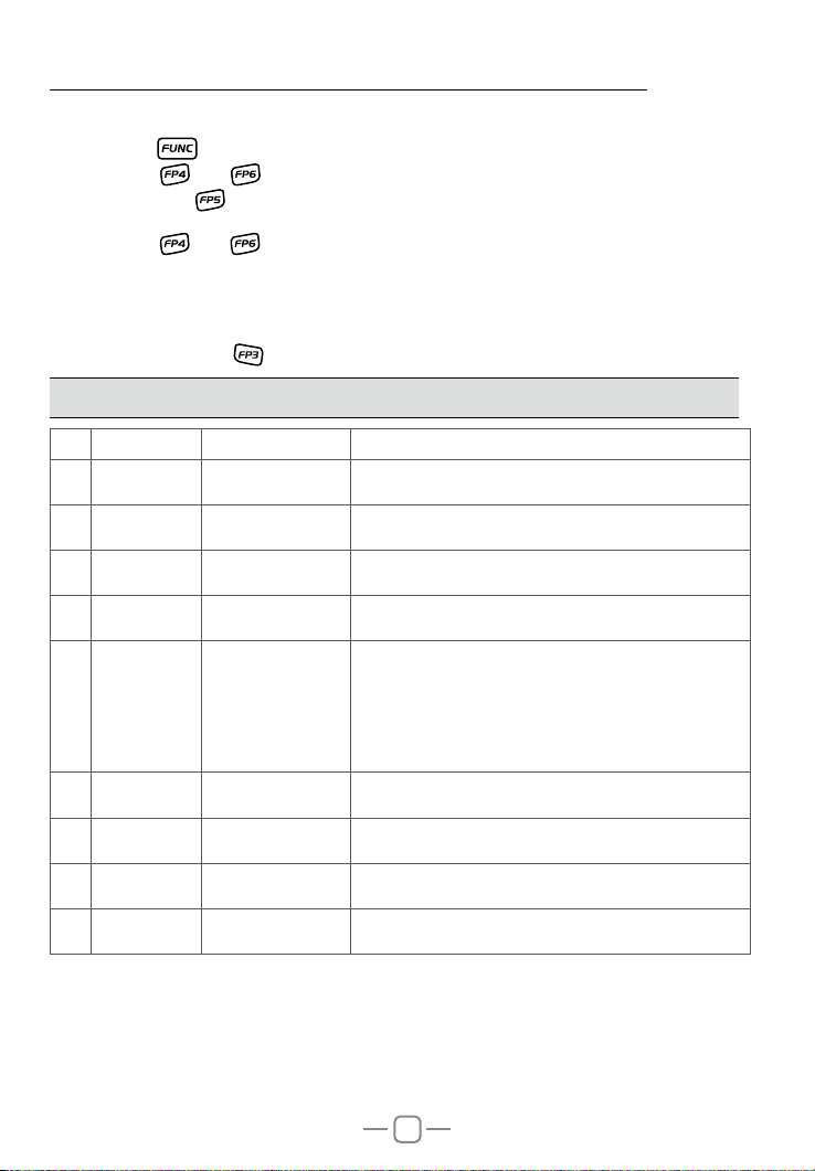
11. SELF –DEFINE KEY SETTING
1.Long press key to enter main MENU interface.
short press
group.(Short press
2.Press [PUSH] key to KEY MENU .
3.Turn channel switch to choose wanted function
4.Short press [PUSH] key to choose Key function group.
5.Short press P1~P6 keys to choose the key for allocated the function.
6.Press
key, key or Turn channel switch to move cursor, to choose menu
key can fast turn page).
key to conrm and exit.
Page 24
12. SPECIFICATIONS
GENERAL
Modulation Mode AM/FM
Frequency Range
Frequency Tolerance ±5.0ppm
Input Voltage 12/24V
Dimensions(in mm) 124(W) x 163(D) x 39(H)
Weight Approx.670g
Ferquency Control PLL Synthesizer
Operating Temperature Range -20° C TO + 55° C
Transmit 2A MAX
Current Drain
Antenna Connector UHF,SO-239
Power Output 4 WattsFM/AM
Transmission interference inferior to 4nW(-54dBm)
Frequency Response 300-3000Hz
Modulated signal distortion inferior to 5%
Output Impedance 50 ohms
Sensitivity Less than 1uV for 10dB(S+N)/N
Image Rejection 70dB
Adjacent Channel Rejection 60dB
IF Frequencies
Automatic Gain Control(AGC)
Squelch less than 1uV
Audio Output Power 3 watts into 8 ohms
Frequency Response 300-3000Hz
Receive Squelched 0.3A
VOL Max 0.8A
TRANSMITTER
28.000 ~ 29.700MHz (FM)
28.000 ~ 29.700MHz (AM)
RECEIVER
1st 10.695MHz
2nd 455KHz
Less than 10dB change in audio
Output for inputs from 10 to 50000uV
19
 Loading...