

Page 1
Power-PRO™ XT
Model 6500
Operations/Maintenance Manual
For Parts or Technical Assistance:
USA: 1-800-327-0770 (option 2)
Canada: 1-888-233-6888
2008/11 6500-309-001 REV A www.stryker.com
Page 2

Page 3

Table of Contents
Introduction...............................................................................6
Specifications .........................................................................6
WARNING / CAUTION / NOTE DEFINITION ....................................................8
Symbols .................................................................................9
Warranty................................................................................10
Stryker EMS Return Policy ...............................................................11
Return Authorization....................................................................11
Damaged Merchandise..................................................................11
International Warranty Clause .............................................................11
Patent Information .....................................................................11
Summary of Safety Precautions...............................................................12
Component Identification.................................................................... 17
Product Inspection ........................................................................18
General Inspection .....................................................................18
Setup Procedures .........................................................................20
Cot Load Height and “Jog” Function ........................................................21
Cot Fastener Installation ....................................................................22
In-Fastener Shut-Off....................................................................24
Vehicle Safety Hook Installation ...............................................................25
Ambulance Configuration ................................................................25
Required Hardware for Installation of the Safety Hook (Not Supplied) ................................25
Positioning and Installing the Safety Hook ....................................................26
Cot Features.............................................................................28
Using Restraint Straps ..................................................................28
Using The Restraint Belt Extension (Optional) .................................................30
Pedi-Mate™ Infant Restraint System (Optional) Attachment Instructions...............................31
Operating The Optional Wheel Lock(s) ......................................................33
Adjusting The Wheel Locking Force.........................................................34
Adjusting the Cot Retaining Post ...........................................................34
Adjusting the Footrest ...................................................................35
Operating the Backrest..................................................................36
Operating the Siderails ..................................................................36
Battery Power Indicator..................................................................37
Hour Meter ..........................................................................38
Installing the Optional Head End Storage Flat..................................................39
Installing the Optional Backrest Storage Pouch.................................................40
Using the Optional Equipment Hook ........................................................41
Operating the 2-Stage I.V. Pole (Optional Equipment) ............................................42
Operating the 3-Stage I.V. Pole (Optional Equipment) ............................................43
Cot Operation............................................................................44
Operating Guidelines ...................................................................44
Proper Lifting Techniques ................................................................44
Transferring the Patient to the Cot..........................................................45
www.stryker.com 650 0- 309 -0 01 REV A 3
Page 4

Table of Contents
Cot Operation (Continued)
Using the Optional Transfer Flat ...........................................................45
Ambulance Cot Motion ..................................................................45
Loading the Cot into a Vehicle with Two Operators - Powered Method ...............................46
High Speed Retract/Extend...............................................................47
Loading the Cot into a Vehicle with Two Operators at the Foot End..................................47
Loading an Empty Cot into a Vehicle with One Operator - Powered Method............................48
Unloading the Cot from a Vehicle with Two Operators - Powered Method .............................49
Unloading the Cot from a Vehicle With One Operator - Powered Method..............................50
Manual Override Operation...............................................................51
Loading the Cot into a Vehicle with Two Operators - Manual Method ................................52
Unloading the Cot from a Vehicle with Two Operators - Manual Method..............................53
Unloading an Empty Cot from a Vehicle with One Operator - Manual Method ..........................54
Adjusting Cot Height ....................................................................55
Using Additional Assistance ..............................................................55
Operating the Retractable Head Section .....................................................56
Battery Operation ......................................................................57
Cleaning................................................................................58
Washing Procedure ....................................................................58
Washing Limitations ....................................................................58
Removal of Iodine Compounds ............................................................59
Preventative Maintenance ...................................................................60
Base Lubrication ......................................................................61
Regular Inspection and Adjustments ........................................................62
Maintenance Record .......................................................................65
Training Record...........................................................................66
Cot Assembly ............................................................................67
Base Assembly...........................................................................75
Outer Lift Tube Assembly, Base Pivot - 6500-301-021 ...............................................80
Inner Lift Tube Assembly, Base Pivot - 6500-301-022 ...............................................81
Inner Lift Tube, Litter Pivot - 6500-001-034 ......................................................82
Inner Lift Tube, Litter Pivot - 6500-001-035 ......................................................83
Outer Rail, Patient Right Assembly .............................................................84
Outer Rail, Patient Left Assembly..............................................................86
Hall Sensor Assembly ......................................................................88
Sensor Housing Assembly...................................................................89
Powerplant Assembly ......................................................................90
Hydraulic Sub-Assembly - 6500-001-030 ........................................................92
Foot End Assembly ........................................................................93
Switch Assembly - 6500-001-016..............................................................97
Fowler Assembly..........................................................................98
Trend Assembly ..........................................................................99
Head Section Assembly - 6500-001-020........................................................ 100
4 650 0- 309 -0 01 REV A www.stryker.com
Page 5

Table of Contents
Assembly Drawings (Continued)
Head Section Lock Assembly - 6500-001-026 ...................................................102
In-Fastener Shut-Off Assembly - 6500-001-027 .................................................. 103
Optional Oxygen Bottle Holder - 6500-140-000 ................................................... 104
Optional Oxygen Bottle Holder Assembly - 6500-001-040 ...........................................10 5
Optional Head End Oxygen Bottle Holder - 6500-141-000 ...........................................106
Removable Oxygen Bottle Holder Assembly - 6080-140-010 .........................................107
Two-Stage I.V. Pole Assembly Patient Right - 6500-210-000..........................................108
Three-Stage I.V. Pole Assembly Patient Right - 6500-215-000......................................... 10 8
Three-Stage I.V. Pole Assembly Patient Right - 6500-001-043 ........................................ 110
Two-Stage I.V. Pole Assembly Patient Left - 6500-211-000 ..........................................111
Three-Stage I.V. Pole Assembly Patient Left - 6500-216-000 .........................................111
Two-Stage I.V. Pole Assembly Patient Left - 6500-001-042........................................... 112
Three-Stage I.V. Pole Assembly Patient Left - 6500-001-044 ......................................... 113
Two-Stage I.V. Pole Assembly, Dual - 6500-212-000 .......................................114
Three Stage I.V. Pole Assembly, Dual - 6500-217-000 .............................................. 114
Optional Defibrillator Platform - 6500-170-000.................................................... 115
Optional Head Extension - 6100-044-000 .......................................................116
Optional Head Extension Assembly - 6100-044-012 ............................................... 117
Troubleshooting Guide..................................................................... 118
Electronics and Hydraulics Locator ........................................................ 118
Hydraulic Manifold Components Locator .................................................... 119
Electronics Assembly Wiring Schematics.................................................... 120
Electrical System Block Diagram .........................................................121
Troubleshooting Guide .................................................................123
Recycling Passport .......................................................................12 7
Product: 6500-700-006 ................................................................12 7
Product: 6500-001-016 ................................................................. 12 8
Product: 6500-001-028 ................................................................. 12 9
Product: 6500-001-015 ................................................................. 13 0
Product: 6500-001-014 .................................................................13 0
Product: 6500-001-030 ................................................................ 13 1
Product: 6500-001-159 ................................................................. 13 2
Quick Reference Replacement Part List ........................................................ 13 3
www.stryker.com 650 0- 309 -0 01 REV A 5
Page 6

Introduction
INTRODUCTION
This manual is designed to assist you with the operation and maintenance of the Power-PRO™ XT
Ambulance Cot. Read it thoroughly before using the equipment or beginning any maintenance on it.
SPECIFICATIONS
Maximum Cot Load Capacity 700 pounds 315 kg
Maximum Unassisted Lift Capacity 500 pounds 225 kg
Backrest Articulation/Shock Position 2° to 73° / +15°
Overall Length/Minimum Length/Width 81" / 63" / 23" 206 cm / 160 cm / 58,5 cm
1
Height
2
Weight
Caster Diameter/Width 6" / 2" 15,2 cm / 5,1 cm
Minimum Operators Required for Loading/
Unloading an Occupied Cot
Minimum Operators Required for Loading/
Unloading an Unoccupied Cot
Recommended Fastener Systems Model 6370 or 6377 Floor Mount Type
Recommended Loading Height
3
Roll-In Style Yes
Single Wheel Lock / Double Wheel Lock Optional
Hydraulic Oil Stryker Part Number 6500-001-293
Battery System DeWA LT® 24 Volt NiCd Battery
- Battery Stryker Part Number 6500-700-006
- Charger Stryker Part Number 6500-070-000 (120 Volt)
1
Adjustable from 14" to 41.5" 35,5 cm to 105 cm
122 pounds 55,3 kg
2
1
Model 6371 Wall Mount Type
Adjustable up to 36" 91 cm
Part Number 6500-072-000 (12/24 Volt)
1
Height measured from bottom of mattress at seat section to ground level.
2
Cot is weighed with 1 battery and without mattress and restraints.
3
Cot may be set to any ambulance deck height ranging from 26" to 36" (66 cm to 91 cm).
Stryker reserves the right to change specifications without notice.
The Power-PRO™ XT is designed to conform to the Federal Specification for the Star-of-Life Ambulance (KKK-A-1822).
The Power-PRO™ XT is designed to be compatible with competitive cot fastener systems.
DeWA LT® is a registered trademark of Black & Decker Inc.
Patents pending.
The yellow and black color scheme is a proprietary trademark of Stryker Corporation.
Return To Table of Contents
6 650 0- 309 -0 01 REV A www.stryker.com
Page 7
Introduction
Contact Stryker Customer Service or Technical
Support at: (800) 327-0770 or (269) 324-6500.
Stryker Medical
3800 E. Centre Avenue
Portage, MI 49002
USA
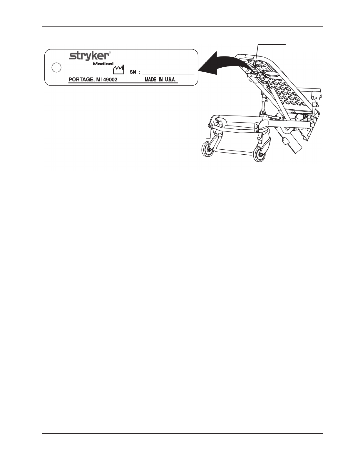
Please have the serial number of your Stryker product when
calling Stryker Customer Service or Technical Support.
Include the serial number in all written communication.
Figure 1 - Cot Serial Number & Location
Serial Number
HEAD END
Return To Table of Contents
www.stryker.com 650 0- 309 -0 01 REV A 7
Page 8

Introduction
WARNING / CAUTION / NOTE DEFINITION
The words WARNING, CAUTION and NOTE carry special meanings and should be carefully reviewed.
WARNING
Alerts the reader about a situation, which if not avoided, could result in death or serious injury. It may also describe potential serious adverse reactions and safety hazards.
CAUTION
Alerts the reader of a potentially hazardous situation, which if not avoided, may result in minor or moderate injury to
the user or patient or damage to the equipment or other property. This includes special care necessary for the safe
and effective use of the device and the care necessary to avoid damage to a device that may occur as a result of use
or misuse.
NOTE
This provides special information to make maintenance easier or important instructions clearer.
Return To Table of Contents
8 650 0- 309 -0 01 REV A www.stryker.com
Page 9
Symbols
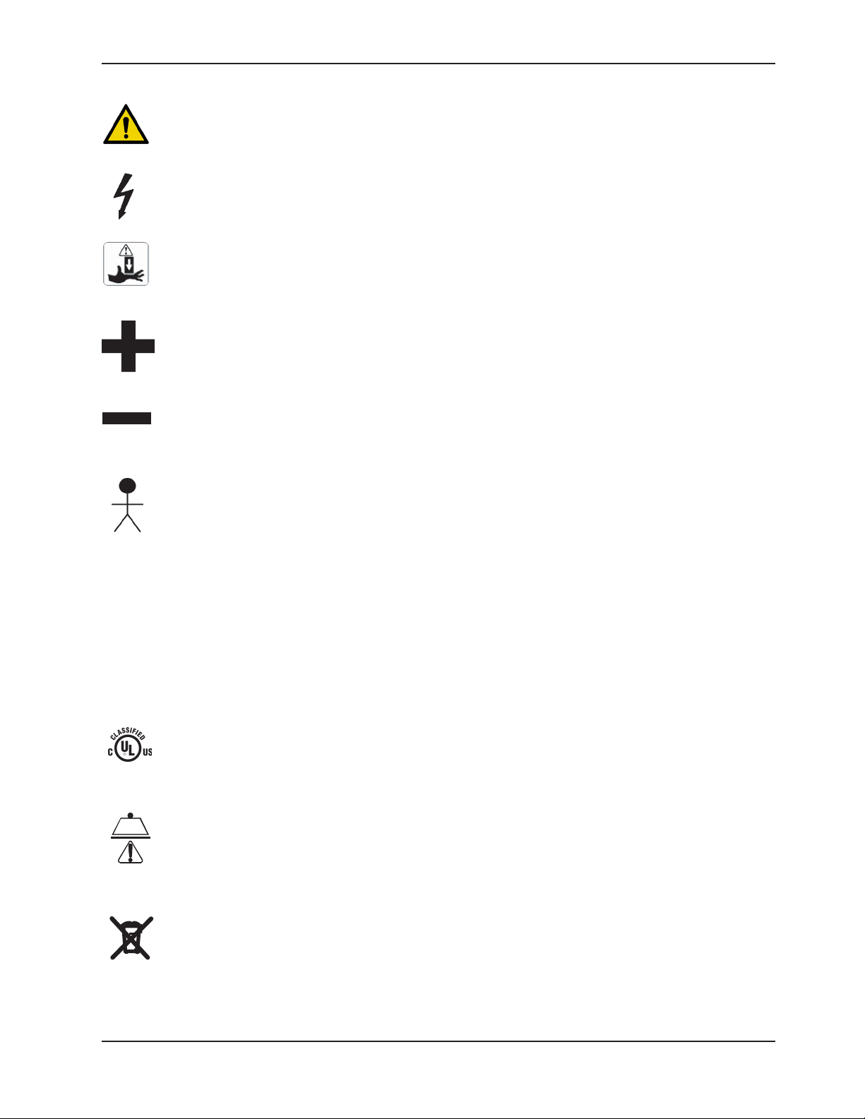
Warning, consult accompanying documentation
Dangerous Voltage Symbol
Pinch Point
Extend
Retract
IPX6
Type B Equipment: equipment providing a particular degree of protection against electric shock,
particularly regarding allowable leakage current and reliability of the protective earth connection.
Internally Powered Equipment: Equipment able to operate from an internal (removable) electric power
source.
Mode of Operation: 10% (1 Min. On / 5 Min. Off)
Protection from powerful jets.
Medical Equipment Classified by Underwriters Laboratories Inc. With Respect to Electric Shock, Fire, and
Mechanical Hazards Only in Accordance with UL 60601−1, and CAN/CSA C22.2 No. 601.1.
Safe Working Load Symbol
In accordance with European Directive 2002/96/EC on Waste Electrical and Electronic Equipment, this
symbol indicates that the product must not be disposed of as unsorted municipal waste, but should be
collected separately. Refer to your local distributor for return and/or collection systems available in your
country.
Return To Table of Contents
www.stryker.com 650 0- 309 -0 01 REV A 9
Page 10

Warranty
Stryker EMS, a division of the Stryker Corporation, offers one warranty option in the United States:
Two (2) year parts and labor. Stryker EMS warrants to the original purchaser that its products
should be free from manufacturing non-conformances that affect product performance and
customer satisfaction for a period of two (2) years after date of delivery. Stryker’s obligation
under this warranty is expressly limited to supplying replacement parts and labor for, or
replacing, at its option, any product that is, in the sole discretion of Stryker, found to be
defective. Expendable components, i.e. mattresses, restraints, I.V. poles, storage nets, storage
pouches, O2 straps, and other soft goods, have a one (1) year limited warranty.
Stryker Medical EMS products are designed for a 7 year expected service life under normal
use, conditions, and with appropriate periodic maintenance as described in the maintenance
manual for each device. Stryker warrants to the original purchaser that the welds on its EMS
products will be free from structural defects for the expected 7 year life of the EMS product as
long as the original purchaser owns the product. Original purchasers will also obtain a three
(3) year limited parts warranty for the X-frame components of the POWER PRO cot and a three
(3) year limited power train warranty covering the motor pump assembly and hydraulic cylinder
assembly. Stryker’s obligation under this three (3) year limited warranty is expressly limited to
supplying replacement parts and labor for, or replacing, at its option, any part that is, in the sole
discretion of Stryker, found to be defective.
If Stryker requests, products or parts for which an original purchaser makes a warranty claim,
the purchaser shall return the product or part prepaid freight to Stryker’s factory.
Any improper use or alteration or repair by unauthorized service providers in such a manner
as in Stryker’s judgment affects the product materially and adversely, shall void this warranty.
Any repair of Stryker products using parts not provided or authorized by Stryker shall void this
warranty. No employee or representative of Stryker is authorized to change this warranty in
any way.
This statement constitutes Stryker EMS’s entire warranty with respect to the aforesaid
equipment. STRYKER MAKES NO OTHER WARRANTY OR REPRESENTATION EITHER
EXPRESSED OR IMPLIED, EXCEPT AS SET FORTH HEREIN. THERE IS NO WARRANTY OF
MERCHANTABILITY AND THERE ARE NO WARRANTIES OF FITNESS FOR ANY PARTICULAR
PURPOSE. IN NO EVENT SHALL STRYKER BE LIABLE HEREUNDER FOR INCIDENTAL OR
CONSEQUENTIAL DAMAGES ARISING FROM OR IN ANY MANNER RELATED TO SALES OR
USE OF ANY SUCH EQUIPMENT.
DeWALT® Product Warranty
Any DeWA LT® product purchased from Stryker EMS is covered for a period of one (1) year
after date of delivery. Stryker’s obligation under this warranty is expressly limited to supplying
replacement parts and labor for, or replacing, at its option, any product that is, in the sole
discretion of Stryker, found to be defective.
Return To Table of Contents
10 650 0- 309 -0 01 REV A www.stryker.com
Page 11

Warranty
STRYKER EMS RETURN POLICY
Cots, Stair Chairs, Evacuation Chairs, Cot Fasteners and Aftermarket Accessories may be
returned up to 180 days of receipt if they meet the following guidelines:
Prior to 30 Days
• 30daymoneybackguaranteeineffect
• StrykerEMSisresponsibleforallcharges
• Returnswillnotbeapprovedonmodifieditems
Prior to 90 Days
• Productmustbeunused, undamaged and in the original packaging
• Customerisresponsiblefora10%restockingfee
Prior to 180 Days
• Productmustbeunused, undamaged and in the original packaging
• Customerisresponsiblefora25%restockingfee
RETURN AUTHORIZATION
Merchandise cannot be returned without approval from the Stryker Customer Service
Department. An authorization number will be provided which must be printed on the returned
merchandise. Stryker reserves the right to charge shipping and restocking fees on returned
items.
SPECIAL, MODIFIED, OR DISCONTINUED ITEMS NOT SUBJECT TO RETURN.
DAMAGED MERCHANDISE
ICC Regulations require that claims for damaged merchandise must be made with the carrier
within fifteen (15) days of receipt of merchandise. DO NOT ACCEPT DAMAGED SHIPMENTS
UNLESS SUCH DAMAGE IS NOTED ON THE DELIVERY RECEIPT AT THE TIME OF RECEIPT.
Upon prompt notification, Stryker will file a freight claim with the appropriate carrier for damages
incurred. Claim will be limited in amount to the actual replacement cost. In the event that this
information is not received by Stryker within the fifteen (15) day period following the delivery of
the merchandise, or the damage was not noted on the delivery receipt at the time of receipt,
the customer will be responsible for payment of the original invoice in full.
Claims for any short shipment must be made within thirty (30) days of invoice.
INTERNATIONAL WARRANTY CLAUSE
This warranty reflects U.S. domestic policy. Warranty outside the U.S. may vary by country.
Please contact your local Stryker Medical representative for additional information.
PATENT INFORMATION
products are covered by one or more of the following patents:
United States 5,575,026 6,276,010 6,648,343 6,908,133 6,796,757
5,537,700 6,125,485 6,735,794 7,100,224 7,398,571
D527,10 3
Other Patents Pending
Return To Table of Contents
www.stryker.com 650 0- 309 -0 01 REV A 11
Page 12

Summary of Safety Precautions
The following is a list of safety precautions that must be observed when operating or servicing this unit. The precautions
are repeated throughout the manual, where applicable. Carefully read this list before using or servicing the unit.
WARNINGS
Do not modify the ambulance cot or any components of the cot, including the hydraulic unit. Modifying the product •
can cause unpredictable operation resulting in injury to the patient or operator. Modifying the product will also void
its warranty.
The in-fastener shut-off module must be positioned properly before placing the ambulance cot into EMS service. •
Failure to install the in-fastener shut-off module may cause injury to the patient or operator and/or damage to the
vehicle.
It is the responsibility of the cot operator to ensure the ambulance cot being used in the Stryker cot fastener •
system meets the installation specifications listed on page 23. Injury may result if a non-compatible ambulance cot
is used in the Stryker cot fastener system.
Have the vehicle safety hook installed by a certified mechanic. Improper safety hook installation can result in injury •
to the patient or operator and/or damage to the cot.
Failure to install the vehicle safety hook can result in injury to the patient or operator. Install and use the safety •
hook as described in this manual. To avoid injury, verify the safety bar has engaged the safety hook before
removing the ambulance cot from the patient compartment.
Install the vehicle safety hook at least 1/8" (3 mm) from the edge of the rear ambulance door. After installation, •
verify that the undercarriage locks in the load position without contacting the emergency vehicle bumper.
The ambulance cot must have at least 5/8" (1,6 mm) of clearance between the emergency vehicle bumper and •
the ambulance cot to disengage the safety bar when unloading the product from the ambulance. Verify that the
product is locked in a rolling position before disengaging the safety bar from the safety hook (if equipped).
To avoid accidental release of the Pedi-Mate™, and possible injury to the infant, ensure that the restraint buckle •
is located away from obstructions on the ambulance cot or accessories.
Never apply the optional wheel lock(s) while a patient is on the ambulance cot. Tipping could occur if the •
ambulance cot is moved while wheel locks are applied, resulting in injury to the patient or operator and/or damage
to the product.
Never install or use wheel locks on an ambulance cot with excessively worn wheels. Installing or using wheel locks •
on wheels with less than a 6" (16 cm) diameter could compromise the holding ability of the wheel lock, resulting
in injury to the patient or operator and/or damage to the product or other equipment.
To avoid risk of electric shock, never attempt to open the battery pack for any reason. If the battery pack case •
is cracked or damaged, do not insert it into the charger. Return damaged battery packs to a service center for
recycling.
Do not remove the battery when the ambulance cot is activated.•
Avoid contact with a wet battery or battery enclosure. Contact may cause injury to the patient or operator.•
When the optional head-end storage flat is being used, ensure it does not interfere with the operation of the •
retractable head section, safety bar and safety hook. Injury to the patient or operator could result.
Improper usage of the ambulance cot can cause injury to the patient or operator. Operate the ambulance cot only •
as described in this manual.
Entanglement in powered ambulance cot mechanisms can cause serious injury. Operate the ambulance cot only •
when all persons are clear of the mechanisms.
Practice changing height positions and loading and unloading the ambulance cot until operation of the product is •
fully understood. Improper use can cause injury.
Do not allow untrained assistants to assist in the operation of the ambulance cot. Untrained technicians/assistants •
can cause injury to the patient or themselves.
Ensure proper hand placement on hand grips. Hands should be clear of red safety bar pivots while loading and •
unloading the cot.
Do not ride on the base of the ambulance cot. Damage to the product could occur, resulting in injury to the patient •
or operator.
Grasping the ambulance cot improperly can cause injury. Keep hands, fingers and feet away from moving parts. •
Return To Table of Contents
12 6500- 309- 001 REV A ww w.stryker.com
Page 13

Summary of Safety Precautions
WARNINGS (CONTINUED)
Transporting the cot sideways can cause the cot to tip, resulting in possible damage to the product and/or injury to •
the patient or operator. Transporting the cot in a lowered position, head or foot end first, will minimize the potential
of a cot tip.
Any emergency vehicle to be used with this ambulance cot • must have the in-fastener shut-off system installed.
Always use all restraint straps to secure the patient to the ambulance cot. An unrestrained patient may fall from •
the ambulance cot and be injured.
Do not attach restraints to the base or cross tubes, improper restraint attachment could result in damage to the •
cot further resulting in injury to the patient or operator.
Never leave a patient unattended on the ambulance cot or injury could result. Hold the ambulance cot securely •
while a patient is on the cot.
Siderails are not intended to serve as a patient restraint device. Refer to • pages 28 and 30 for proper restraint strap
usage. Failure to utilize the siderails properly could result in patient injury.
High obstacles such as curbing, steps or rough terrain can cause the ambulance cot to tip, possibly causing injury •
to the patient or operator. Transporting the cot in lower positions can reduce the potential of a cot tip. If possible,
obtain additional assistance (see page 55 for a reference chart) or take an alternate route.
Whenever the weight of the ambulance cot and patient is off the wheels, the ambulance cot will • automatically
enter the high speed retract mode if the retract button is pressed.
Once the weight is off the ground, the operator(s) must support the load of the patient, ambulance cot and any •
accessories. Failure to support the load properly may cause injury to the patient or operator.
To avoid injury, verify the safety bar has engaged the safety hook before removing the ambulance cot from the •
patient compartment.
Do not pull or lift on the safety bar when unloading the ambulance cot. Damage to the safety bar could result and •
injury to the patient or operator could occur.
Do not press the extend (+) button until the safety bar engages the safety hook.•
To avoid injury, always verify that the head section is locked into place prior to operating the ambulance cot (see •
page 54). The head section must be extended and locked into position before loading/unloading the ambulance
cot.
When using a standard ambulance cot fastener, do not load the cot into the vehicle with the head section retracted. •
Loading the cot with the head section retracted may cause the product to tip or not engage properly in the cot
fastener, possibly causing injury to the patient or operator and/or damage to the cot.
The one person loading and unloading procedures are for use only with an empty ambulance cot. Do not use the •
procedures when loading/unloading a patient. Injury to the patient or operator could result.
Do not attempt to operate the ambulance cot when loaded into a cot fastener. The in-fastener shut-off is • only a
means for disabling the electronic functionality. Damage to the product or injury to the patient or operator may
occur.
In-fastener shut-off must be installed in all ambulances in which the cot will be used.•
Use any appropriate personal safety equipment (goggles, respirator, etc.) to avoid the risk of inhaling contagion. •
Use of power washing equipment can aerate contamination collected during the use of the ambulance cot.
Failure to properly clean or dispose of contaminated mattress or other ambulance cot components will increase •
the risk of bloodborne pathogens and may cause injury to the patient or operator.
Hydraulically raising or lowering the cot may temporarily affect electronic patient monitoring equipment. For best •
results, patient monitoring should be conducted when the cot is idle.
SOME CLEANING PRODUCTS ARE CORROSIVE IN NATURE AND MAY CAUSE DAMAGE TO THE PRODUCT IF •
USED IMPROPERLY. If the products described above are used to clean Stryker patient care equipment, measures
must be taken to insure the cots are wiped with clean water and thoroughly dried following cleaning. Failure to
properly rinse and dry the cots will leave a corrosive residue on the surface of the cots, possibly causing premature
corrosion of critical components.
Escaping fluid under pressure can penetrate the skin causing serious injury. Avoid the hazard by relieving pressure •
before disconnecting hydraulic or other lines. Tighten all connections before applying pressure. If an accident
occurs, see a doctor immediately. Any fluid injected into the skin must be surgically removed within a few hours
or gangrene may result. Doctors unfamiliar with this type of injury should reference a knowledgeable medical
source.
Return To Table of Contents
www.stryker.com 650 0- 309 -0 01 REV A 13
Page 14

Summary of Safety Precautions
CAUTIONS
Set the cot height limit to the proper stop height prior to operation.•
Installation of the safety hook should be done by a certified mechanic familiar with ambulance construction. •
Consult the vehicle manufacturer before installing the safety hook and be sure the installation of the safety hook
does not damage or interfere with the brake lines, oxygen lines, fuel lines, fuel tank or electrical wiring of the
vehicle.
Ensure that restraints are not entangled in the base frame when raising and lowering the cot. •
Wheel locks are only intended to help prevent the ambulance cot from rolling while unattended. Wheel locks may •
not provide sufficient resistance on all surfaces or under loads.
The ambulance cot fastener comes preconfigured for an X-Frame cot, if the fastener has been configured for an •
H-frame style cot, the cot retaining post must be adjusted to accommodate the fastener.
Only use the battery and charger as specified.•
The Power-PRO™ XT is not for use with an AC adaptor.•
Ensure that the battery is charged prior to placing into service. An uncharged or depleted battery may cause poor •
ambulance cot performance.
A preventative maintenance program should be established for all Stryker EMS equipment. Preventative maintenance •
may need to be performed more frequently based on the usage level of the product. Close attention should be
given to safety features including, but not limited to:
Hydraulic power mechanism•
All electrical controls return to off or neutral position when released•
For additional maintenance information, refer to the preventative maintenance section.•
Do not store items under the ambulance cot mattress. Storing items under the mattress can interfere with the •
operation of the ambulance cot.
The weight of the equipment in the head end storage flat (if equipped) must not exceed 40 pounds (18 kg). •
The weight of the equipment in the pocketed backrest storage pouch (if equipped) must not exceed 20 pounds •
(9 kg).
To avoid damage to the equipment hook, the weight of the accessories or equipment must not exceed 20 pounds •
(9 kg).
The weight of the I.V. bags or equipment must not exceed 40 pounds (18 kg) for usage on the I.V. poles •
(if equipped).
The weight of the oxygen bottle cylinder and/or other equipment must not exceed 40 pounds (18 kg) with the •
permanent foot-end oxygen bottle holder (if equipped). Oxygen bottle cylinder should not be stored on the cot or
on the oxygen holder when in the ambulance vehicle.
The weight of the removable oxygen bottle holder and/or other equipment must not exceed 25 pounds (11.3 kg) •
Before operating the cot, clear any obstacles that may interfere and cause injury to the operator or patient.•
The ambulance cot can be set at any height position. Establish the required load height for the ambulance cot •
prior to placing the unit into service.
Loading, unloading or changing the position of a loaded ambulance cot requires a minimum of• two trained
operators. The operator(s) must be able to lift the total weight of the patient, cot and any other items on the cot
(if additional assistance is needed, see page 53 for a reference chart).
When unloading the ambulance cot from the patient compartment, ensure the caster wheels are safely set on the •
ground or damage to the product may occur.
Do not “jog” the ambulance cot past the established load height of the product when the safety bar engages the •
vehicle safety hook or damage may occur to the product.
Remove the battery if the cot is not going to be used for an extended period of time (over 24 hours).•
Remove the battery before washing the cot.•
Do not steam clean or ultrasonically clean this ambulance cot. Maximum water temperature should not exceed •
180 °F/82 °C. Maximum air dry temperature (cart washers) is 240 °F/115 °C. Maximum water pressure should not
exceed 1500 psi/130.5 bar. If a hand held wand is being used to wash the unit, the pressure nozzle must be kept
a minimum of 61 centimeters from the unit. Towel dry all casters and interface points. Failure to comply with these
instructions may invalidate any/all warranties.
Return To Table of Contents
14 6500 -309- 001 REV A w ww.stryker.com
Page 15

Summary of Safety Precautions
CAUTIONS (CONTINUED)
Improper maintenance can cause injury or damage to the product. Maintain the ambulance cot as described in this •
manual. Use only Stryker approved parts and maintenance procedures. Using unapproved parts and procedures
could cause unpredictable operation and/or injury and will void the product warranty.
Failure to use authorized parts, lubricants, etc. could cause damage to the ambulance cot and will void the •
warranty of the product.
Hydraulic hose connections and lines can fail due to physical damage, kinks, age, and exposure. Check hoses and •
lines regularly to avoid damage to the cot. Check and tighten loose connections.
Hydraulic fluid connections can loosen due to physical damage and vibration. Check and tighten loose •
connections.
When charging batteries in an ambulance vehicle, locate the charger either in the forward cab or an enclosed •
compartment (i.e. cabinet).
Do not lubricate the bearings in the X-frame as it will degrade the performance of the Power-PRO™ XT ambulance •
cot and may void its warranty.
NOTES
This manual should be considered a permanent part of the ambulance cot and should remain with the product •
even if the cot is subsequently sold.
Adjustment of the rail clamp assembly may be required in order to compensate for any variation in the cot retaining •
post position depending on the ambulance cot manufacturer and model number.
These are general instructions for installation of the Pedi-Mate™. Safe and proper use of the Pedi-Mate™ is solely •
at the discretion of the user. Stryker recommends all users be trained on the proper use of the Pedi-Mate™ before
using it in an actual situation.
If the arrow on the bottom bracket of the retaining post points toward the head end of the cot, the retaining post •
is set for an X-frame style cot. If the arrow points toward the foot end of the cot the post is set for an H-frame
style cot.
If the push button switch remains activated, the motor will remain halted until the operator releases the button. •
Once the push button is released, depress the appropriate button to “jog” the cot height in either direction.
Add an additional 1/2" (1,3 cm) inch to your deck height measurement to allow for variations with patient weight •
and equipment added to the cot.
The operators must lift the cot slightly off the ground to use the manual extend or retract while a patient is on the •
cot.
Batteries slowly lose power when not on the charger.•
Failure to follow the cleaning directions when using the specified types of cleaners may void this product’s •
warranty.
Activation of the manual release may cause the ambulance cot to drop slowly if less than 40 pounds (18 kg) are •
on the cot.
When operating the manual release, avoid rapid lifting or lowering of the base or movement may appear sluggish; •
lift with a slow constant motion.
In order to achieve the optimal performance of the Power-PRO™ XT, center the patient weight within the width of •
the cot.
Return To Table of Contents
www.stryker.com 650 0- 309 -0 01 REV A 15
Page 16
Summary of Safety Precautions
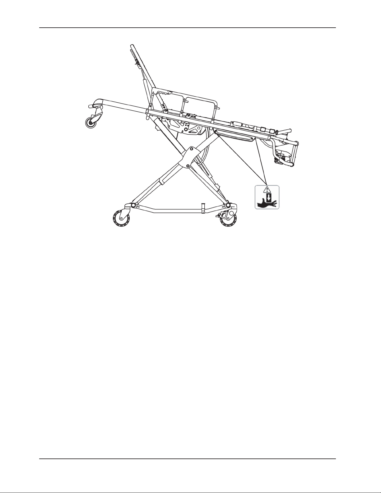
Figure 2 - Potential Pinch Points
WARNING: Pinch Points
Return To Table of Contents
16 650 0- 309 -001 REV A www.stryker.com
Page 17
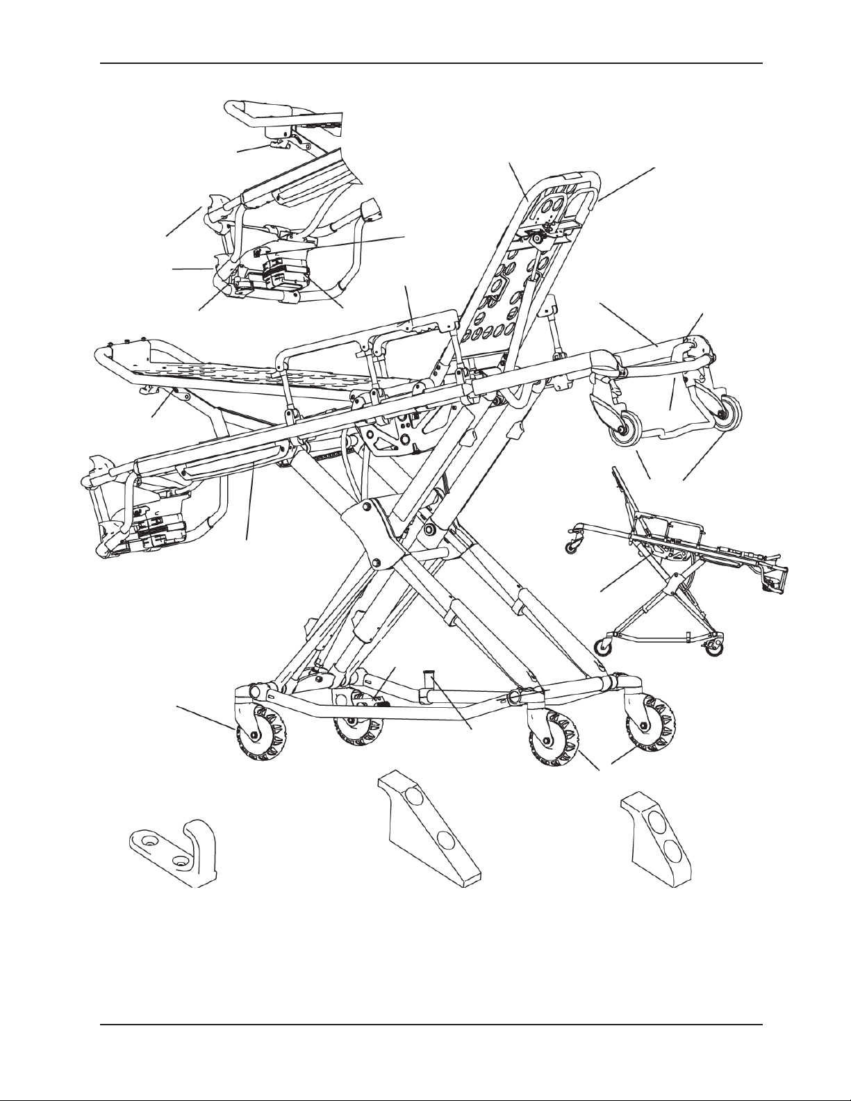
Component Identification
Foot Rest Release
Handle
Height Adjustment
Switches
Manual Release
Leg Rest
Battery
Battery Release
Siderail Release
Backrest
Backrest Adjustment Handle
HEAD END
Retractable
Head Section
Lifting Bar
Loading Wheels
Head Section
Release
Transport Wheels
Height
Sensor
Housing
J Safety Hook
Stryker part number
6092-036-018
Wheel Lock
(Optional)
Cot Retaining Post
Long Safety Hook
Stryker part number
6060-036-018
Figure 3 - Cot Components
Hydraulic Unit
Transport Wheels
Short Safety Hook
Stryker part number
6060-036-017
Return To Table of Contents
www.stryker.com 650 0- 309 -0 01 REV A 17
Page 18

Product Inspection
GENERAL INSPECTION
The condition of the ambulance cot is the responsibility of the owner. It is important that the ambulance cot is working
properly before the product is put into service. Have a qualified service person use the following list and the operation
instructions to check the ambulance cot before the product is put into service.
Unpack the cartons and check all items for proper operation.
Item Routine Page(s)
Battery Unpack batteries and charger
Charge battery according to DeWA LT® instructions
CAUTION
When charging batteries in an ambulance vehicle, locate the charger either in the forward cab or an enclosed
compartment (i.e. cabinet).
Prior to checking the features and condition of the cot, the battery must be charged until the red LED lights continuously
to ensure a full charge. Refer to the DeWA LT® instructions for further charging information.
Once the battery is fully charged, inspect the ambulance cot for the following points:
P/N 6500-001-206
Item Routine Page(s)
Battery Charge spare battery (if necessary) according to DeWALT®
instructions.
Install battery into foot-end enclosure, battery indicator operates. 57
Ensure the battery remains firmly secured. 57
Release and remove battery from foot-end enclosure. 57
Reinstall battery into foot-end enclosure. 57
Hydraulics Inspect motor mount, all fasteners secure. 118
Check cylinder attachments at both ends, all fasteners secure. 118
Inspect main cable, all connections secure. 118
Inspect hoses and cylinder seal for leaks. 118
Electronic
Controls
Manual Release Verify the manual release lever functions properly, adjust accordingly. 51
Check battery indicator, charged. 37
Extend cot to raised position. 55
Verify ”jog” function operating smoothly. 55
Lower to retracted position, cot secures in a mid-height position
(motor does not operate).
Determine and set ambulance vehicle load height 21
Check high speed retract. 47
Extend cot to full height, no drift. 55
With the cot empty, check the raise/lower function. 51
With the cot loaded with a minimum of 45 kg, check the raise/lower
function.
With the cot loaded with a minimum of 45 kg, check the load/unload
function.
P/N 6500-001-206
55
51
48
Return To Table of Contents
18 650 0- 309 -001 REV A www.stryker.com
Page 19

Product Inspection
Item Routine Page(s)
Litter All fasteners secure (reference all assembly drawings).
All welds intact, not cracked or broken.
No bent, broken, or damaged components.
Inspect hand grips, no defects or tears.
Verify siderails operate and latch properly. 36
Verify backrest cylinder operates properly through range of motion. 36
Verify the leg rest operates properly. 35
Install body restraints. Restraints intact and operating properly. 28 - 30
No rips or tears in mattress cover.
Head Section All fasteners secure (reference all assembly drawings).
No bent or broken tubing or sheet metal.
Verify the head section extends and retracts properly. 56
Inspect grip on lift bar, no defects or tears.
Load wheels are secure and roll freely.
Verify the safety bar operates properly. 24
Base All fasteners secure (reference all assembly drawings).
All welds intact, not cracked or broken.
No bent, broken, or damaged components.
Wheels and Tires No debris in wheels.
All wheels secure, rolling and swiveling properly.
Operate wheel locks (if equipped) - wheel secure when engaged,
rolls freely when disengaged.
Cot Fastener Inspect the cot retaining post, fasteners secure. 34
Install in-fastener shut-off module.
Determine and set in-fastener shut-off position.
Verify the ambulance cot and cot fastener fit and function properly.
Install vehicle safety hook. 25 - 27
Verify the safety bar engages the vehicle safety hook properly. 24
Accessories Verify I.V. pole (if equipped) operates properly. 42 - 43
Verify foot-end oxygen bottle holder (if equipped) operates properly.
Verify removable oxygen bottle holder (if equipped) operates properly.
Verify Pedi-Mate™ restraint package (if equipped) operates properly. 31 - 32
Verify accessory hook (if equipped) is installed properly. 41
Verify head extension with pillow (if equipped) installed properly.
Verify pocketed backrest storage pouch (if equipped) installed properly. 40
Head-end storage flat (if equipped) installed properly. 39
Verify pillow (if equipped) included.
Verify 36" restraint extender (if equipped) is included. 30
Verify the Bariatric transfer flat (if equipped) is included. 45
33 - 34
24
Return To Table of Contents
www.stryker.com 650 0- 309 -0 01 REV A 19
Page 20

Setup Procedures
Ensure that all shipping and packaging materials have been removed from the product(s) prior to use.
The patient compartment of the vehicle in which the ambulance cot will be used must have:
• Asmoothrearedgeforcotloading.
• Alevelfloorlargeenoughforthefoldedcot.
• Stryker6370/6374/6377/6378/6379or6371/6375crashstablecotfastener(notincluded).
• In-fastenershut-offmoduleinstalledandpositionedproperly.
• Spacetoinstallthesafetyhook.
When necessary, modify the vehicle to fit the cot. Do not modify the cot.
WARNING
Do not modify the Power-PRO™ XT ambulance cot or any components of the cot, including the hydraulic unit. •
Modifying the product can cause unpredictable operation resulting in injury to the patient or operator. Modifying
the product will also void its warranty.
Any emergency vehicle to be used with this ambulance cot • must have the in-fastener shut-off system installed.
Refer to DeWA LT® manual (Stryker part number 6500-001-206) for battery and charger operation.
NOTE
This manual should be considered a permanent part of the ambulance cot and should remain with the product •
even if the cot is subsequently sold.
Stryker continually seeks advancements in product design and quality. Therefore, while this manual contains the •
most current product information available at the time of printing, there may be minor discrepancies between your
ambulance cot and this manual. If you have any questions, please contact Stryker Customer Service or Technical
Support at (800) 327-0770 or (269) 324-6500.
Return To Table of Contents
20 6500 -309- 001 REV A www.stryker.com
Page 21
Setup Procedures
COT LOAD HEIGHT AND “JOG” FUNCTION
The control mechanism of the ambulance cot utilizes height sensors to set the load height stop for the cot. The sensors
are used to match the load wheel height for a specific ambulance deck height.
The ambulance cot load height can be set from 26" to 36" (66 cm to 91,4 cm), measured from the ground to the bottom
of the load wheel. Establish the height for the cot prior to placing the unit into service. The load height of the ambulance
cot can be modified at anytime, but must be determined and set before the cot is placed into service.
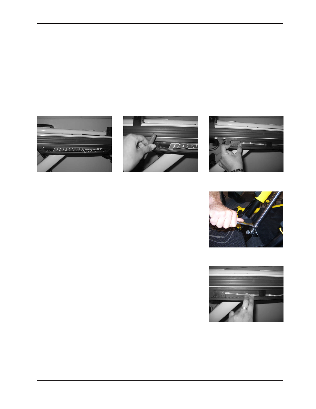
To Set Cot Load Height:
1. Locate the sensor housing on the patient right side of the ambulance cot (Figure 4a), using a T27 Torx wrench,
remove the sensor housing cover by loosening the two (2) screws (one on each end) (Figure 4b).
Figure 4a - Sensor Housing
2. Adjust only the left height sensor (Figure 4c).
a. Move the sensor to the far left, then push the plus (+) button to
move the cot to its highest position.
b. Measure the cot height from the bottom of the load wheels to the
floor.
c. To reach the desired cot height you will need to adjust the cylinder
shaft. Loosen the nut at the end of the shaft (Figure 4d).
i. To increase the height, rotate the shaft clockwise.
Note: Do not exceed 36”
ii. To decrease cot height, rotate the shaft counter-clockwise.
Note: Add an additional 1/2" (1,3 cm) to your deck height
measurement to allow for variations with patient weight
and other equipment added to the cot.
3. After the proper load wheel height is set, ensure all the height sensor
cables are secured and are lying flat in the housing between the sensors
(Figure 4e). Replace the sensor housing cover using the screws removed
in step 1.
4. Following completion of the sensor height adjustment, verify the cot
properly engages the safety hook.
Figure 4b - Loosening Screws
Figure 4c - Adjusting Height
Figure 4d - Adjusting Shaft
Figure 4e - Securing Cables
Return To Table of Contents
www.stryker.com 650 0- 309 -0 01 REV A 21
Page 22

Cot Fastener Installation
The Stryker Cot Fastener systems are designed to be compatible only with cots which conform to the installation
specifications listed on page 23.
WARNING
It is the responsibility of the cot operator to ensure that the cot being used in the Stryker Cot Fastener System meets
the installation specifications listed on page 20. Injury may result if a non-compatible cot is used in the Stryker Fastener
System.
NOTE
Adjustment of the rail clamp assembly may be required in order to compensate for any variation in the cot retaining
post position depending on the ambulance cot manufacturer and model number.
For more detailed instruction and operation instructions for the Stryker Cot Fastener systems, refer to part number
6370-090-010 Cot Fastener Installation/Operation Instructions.
Return To Table of Contents
22 6500 -309- 001 REV A www.stryker.com
Page 23
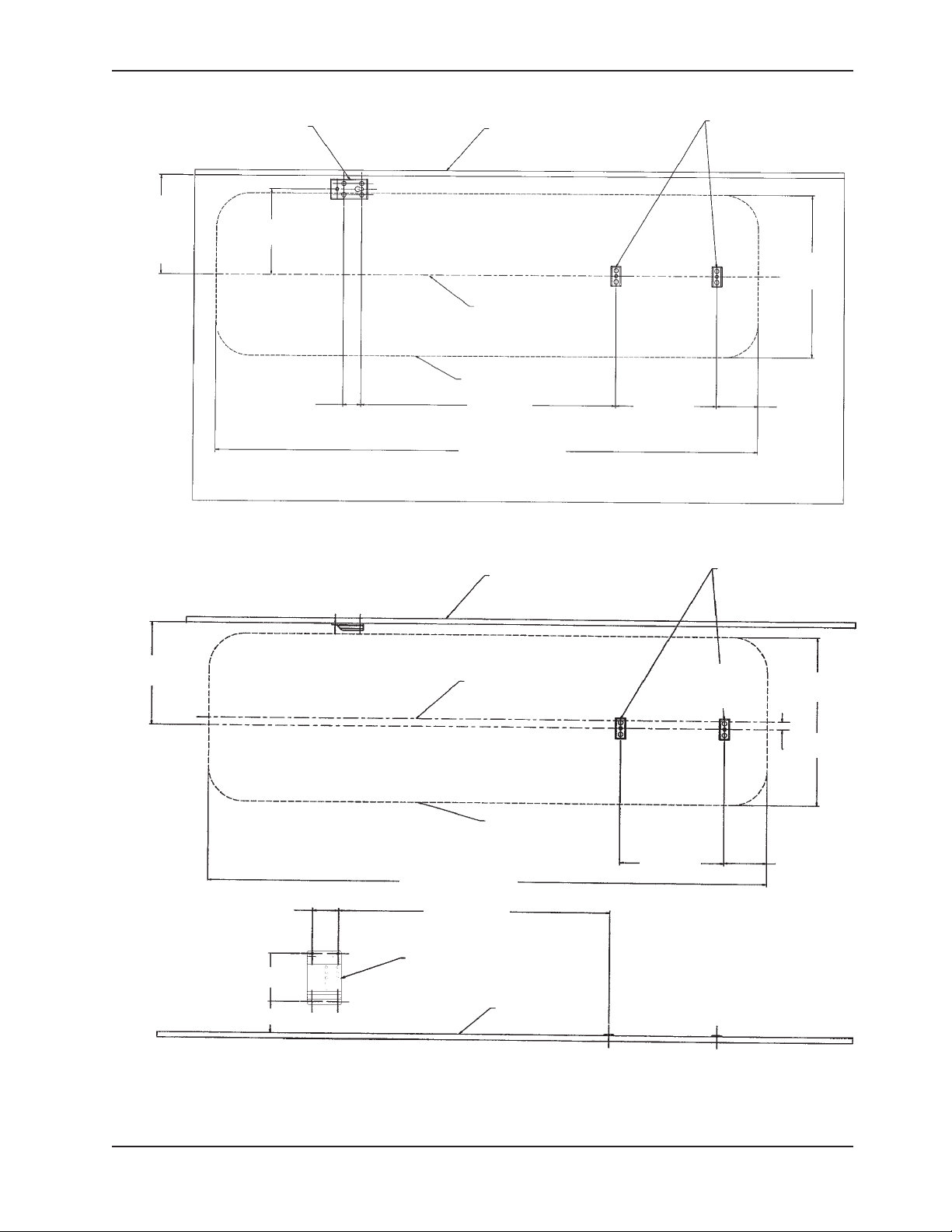
Cot Fastener Installation
RAIL SUPPORT BRACKET
14 5/8 (REF.)
(37,1 cm)
OR DESIRED
POSITION FROM
WALL
REAR OF
AMBULANCE
(REF.)
FLOOR PLATE
12 5/8
WALL OF VEHICLE
(32 cm)
ANTLER FLOOR
PLATES
COT
HEAD
END
COT CENTERLINE
COT PERIMETER
2 5/8
(6,6 cm) (95,6 cm) (37,9 cm) (15,6 cm)
37 5/8
14 15/16
80.000 (REF.)
Figure 5 - Installation Specifications - Floor Mount Fastener
WALL OF VEHICLE
ANTLER FLOOR PLATES
24.000
(REF.)
(61 cm)
6 1/8
14 5/8
(37,1 cm)
REAR OF
AMBULANCE
(REF.)
3 5/8
(9,2 cm)
6 1/2
4 5/16
COT CENTERLINE
COT PERIMETER
14 15/16
80.000 (REF.)
(203 cm)
(37,9 cm) (15,6 cm)
37 3/8
(94,9 cm)
WALL MOUNTING BRACKET
(16,5 cm)
FLOOR OF
(10,9 cm)
VEHICLE
Figure 6 - Installation Specifications - Wall Mount Fastener
COT
HEAD
END
24.000 (REF.)
(61 cm)
1 1/8
(2,9 cm)
6 1/8
Return To Table of Contents
www.stryker.com 650 0- 309 -0 01 REV A 23
Page 24
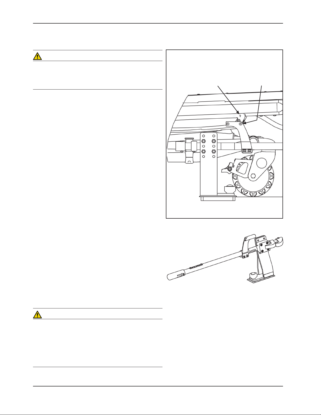
IN-FASTENER SHUT-OFF
Cot Fastener Installation
WARNING
The in-fastener shut-off must be positioned properly before
placing the cot into service. Failure to install the in-fastener
shut-off may cause injury to the patient or operator and/or
damage to the vehicle.
The ambulance cot and fastener system have an integrated
in-fastener shut-off function that disables the cot motor when
the cot is secured in the ambulance cot fastener. Be sure
the bolts on the fastener are tightened before installing the
shut-off bracket. The shut-off magnet must be installed on
the rail clamp assembly before putting the ambulance cot
into service.
1. Place the ambulance cot into a loading position (any
position where the load wheels of the head section meet
the vehicle floor height). Roll the ambulance cot to the
open door of the patient compartment. Lift the vehicle
bumper to the raised position (if possible).
2. Push the ambulance cot forward until the load wheels
are on the patient compartment floor and the safety bar
passes the safety hook.
3. For maximum clearance to lift the base, pull the
ambulance cot until the safety bar engages the safety
hook.
4. Raise the base and push the ambulance cot into the
patient compartment following loading instructions.
5. Engage the extended head section of the cot into the cot
fastener antler and secure the cot post into the fastener
rail clamp.
6. Adjust the magnet assembly along the rail clamp until the
arrow on the sensor housing is lined up with the fastener
as shown in Figure 7.
7. Using a T27 Torx wrench, securely fasten the bolts
attaching the magnet assembly to the rail clamp
assembly.
8. Press the retract (–) button to ensure the motor does
not turn on while the cot is in the fastener. The battery
indictor will still light. If the cot moves, readjust the cot
fastener.
Note: Align the ‘diamond’ on the sensor housing
cover with the pop rivet head on the in-ambulance
shut-off.
Pop Rivet Head“Diamond”
Figure 7 - Cot Engaging Cot Fastener
Figure 8 - In-Fastener Shut-Off Module
WARNING
Do not attempt to operate the ambulance cot when loaded
into a cot fastener. The in-fastener shut-off is only a means
for disabling the electronic functionality.
Damage to the product or injury to the patient or operator
may occur.
In-fastener shut-off must be installed in all ambulances in
which the cot will be used.
Return To Table of Contents
24 650 0- 309 -0 01 REV A www.stryker.com
Page 25
Vehicle Safety Hook Installation
DH
2
2
AMBULANCE CONFIGURATION
The vehicle safety hook is a device shipped with the cot. The safety hook activates the safety bar and prevents the
cot from being removed from the vehicle accidently. The vehicle safety hook was designed to ensure compatibility and
proper operation of the cot during unloading when used in an ambulance vehicle compliant with Federal Regulation
KKK-A-1822.
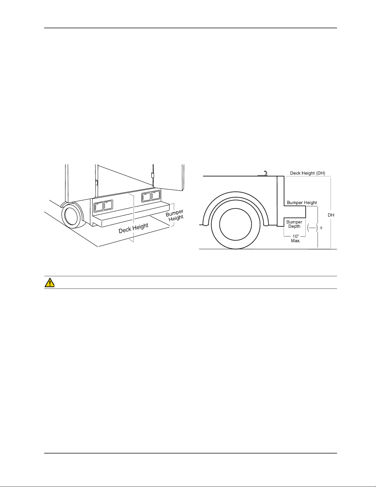
According to federal regulations (reference KKK-A-1822), the bumper height of the ambulance shall be installed
equidistant ± 5 cm (2 inches) from the ambulance floor to the ground level, defined as the ambulance deck height
(Figure 9a). The bumper step shall have a minimum depth of 13 cm (5 inches) and a maximum depth of 25 cm (10
inches). If the bumper depth is greater than 18 cm (7 inches), then the bumper must be able to fold. Installation of the
safety hook into any ambulance vehicle compliant with this federal specification will provide adequate clearance for
the cot base to lower to its fully extended position (Figure 9b). The cot is compatible with all ambulance deck heights
up to 36 inches (91 cm) as long as the ambulance meets the federal specifications outlined in KKK-A-1822.
Figure 9a - Ambulance Deck Height
Figure 9b - Ambulance Deck Height
CAUTION
Set cot height limit to the proper stop height (see • page 21) prior to operation.
Installat• ion of the safety hook should be done by a certified mechanic familiar with ambulance construction.
Consult the vehicle manufacturer before installing the safety hook and be sure the installation of the safety hook
does not damage or interfere with the brake lines, oxygen lines, fuel lines, fuel tank or electrical wiring of the
vehicle.
REQUIRED HARDWARE FOR INSTALLATION OF THE SAFETY HOOK (NOT SUPPLIED)
(2) Grade 5, 1/4”-20 Socket Head Cap Screws*
(2) Grade 5, 1/4”-20 Flat Socket Head Cap Screws*
(2) Flat Washers
(2) Lock Washers
(2) 1/4”-20 Nuts
* The length of the socket head cap screws depends on the thickness of the vehicle floor. Use screws long enough to
go completely through the patient compartment floor, washer and nut by at least two full threads.
Return To Table of Contents
www.stryker.com 650 0- 309 -0 01 REV A 25
Page 26
Vehicle Safety Hook Installation
1/8 inch
(reference only)
Inside Edge of Rear
Doors (When Closed)
POSITIONING AND INSTALLING THE SAFETY HOOK
WARNING
Have the vehicle safety hook installed by a certified mechanic. Improper safety hook installation can cause injury •
to the patient and/or operator or damage to the cot.
Failure to install the safety hook can cause injury to the patient or operator. Install and use the safety hook as •
described in this manual.
Install the safety hook at least 1/8 inch from the edge of the rear ambulance door. After installation, verify the cot •
legs lock into the load position without contacting the ambulance bumper.
To avoid injury, verify the safety bar has engaged the safety hook before removing the cot from the patient •
compartment.
Note:
Stryker EMS recommends that, prior to installation, the certified mechanic plan the placement of the safety hook in
the rear of the vehicle.
Procedure:
Remove the cot from the fastener and unload it from the vehicle.1.
While the cot is being removed, not the position of the load wheels and 2.
the safety bar.
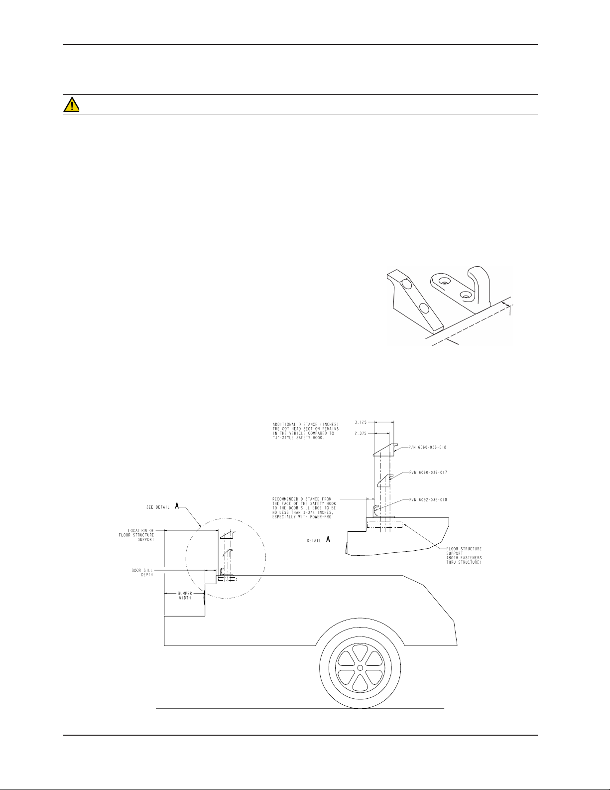
Center the safety hook on the cot safety bar, with the hook facing the 3.
front of the vehicle (Figure 10). For best results, the face of the safety
hook which engages the safety bar should be at least 3-3/4” from the
leading edge of the door sill (Figure 11).
Figure 10 - Safety Hook Placement
Figure 11 - Safety Hook Placement
Return To Table of Contents
26 6 500 -309- 001 REV A www.stryker.com
Page 27
Vehicle Safety Hook Installation
POSITIONING AND INSTALLING THE SAFETY HOOK (CONTINUED)
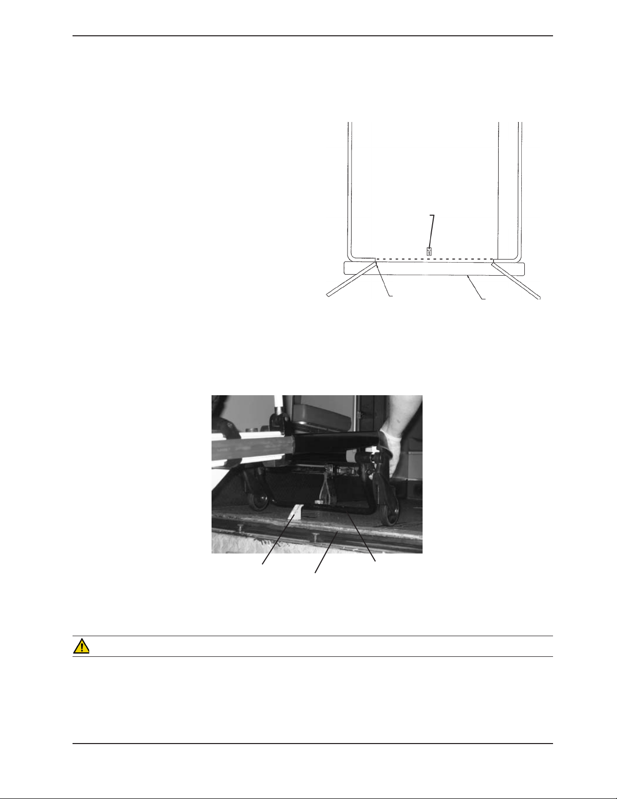
Mark the position of the safety hook on the patient 4.
compartment floor. The safety hook should be
installed as close as possible to the rear of the vehicle
while allowing the vehicle doors to close and checking
that the load wheels always remain on the patient
compartment floor (i.e., wheels do not roll off the door
sill when the cot safety bar engages the safety hook)
when the cot is loaded and unloaded from road and/or
curb height (Figure 12).
Ensure the bumper and bumper step do not interfere 5.
with the operation of the cot.
Drill the holes for the socket head cap screws.6.
Fasten the safety hook to the patient compartment 7.
floor and verify that the safety hook always engages
the cot safety bar when the cot is unloaded from the
vehicle (Figure 13).
Note
If the ambulance cot can be removed by rolling to one
side of the vehicle and not engaging the safety hook,
an additional safety hook should be installed.
Safety Hook
Figure 12 - Safety Hook Placement
Top View of Vehicle
Door Frame
Squad Bench
Bumper
Safety Hook
Floor Edge
Safety Bar
Figure 13 - Safety Bar Engaging Safety Hook
WARNING
The cot must have at least 5/8” of clearance between the ambulance bumper and the cot to disengage the safety •
bar when unloading the cot from the ambulance. Verify the cot legs lock into the load position before disengaging
the safety bar from the safety hook. Failure to properly lock the cot into position can cause injury to the patient or
operator and/or damage to the cot.
Return To Table of Contents
www.stryker.com 650 0- 309 -0 01 REV A 27
Page 28
Cot Features
USING RESTRAINT STRAPS
WARNING
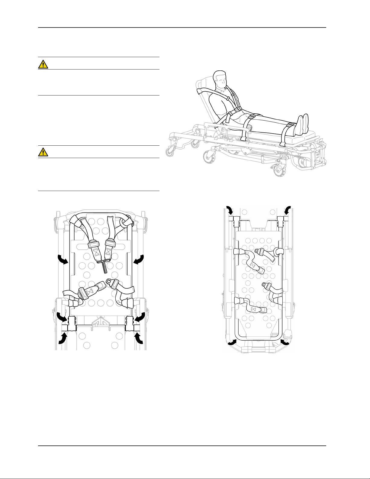
Always use all restraint straps to secure the patient
on the cot. An unrestrained patient may fall from
the cot and be injured.
Always secure the patient on the cot with all the
restraint straps. Buckle the restraints across the
patient’s chest/shoulders, waist and legs (Figure
14). Keep the restraint straps buckled when the
cot is not being used with a patient to avoid damage to the buckles and straps.
WARNING
Do not attach restraints to the base or crosstubes, improper restraint attachment could result
in damage to the cot further resulting in injury to
the patient or operator.
Figure 14 - Safety Restraints
Figure 15 - Head Section Restraints
Wrap the strap around the cot frame and back through the loop on the end of the strap as shown in Figures 15 and 16.
The arrows indicate alternate attachment areas.
When attaching the restraint straps to the cot, remember the attachment points should provide both strong anchorage
and proper restraint position while not interfering with equipment and accessories.
Return To Table of Contents
28 6 500 -3 09-001 REV A www.stryker.com
Figure 16 - Foot Section Restraints
Page 29
USING RESTRAINT STRAPS (CONTINUED)
Cot Features
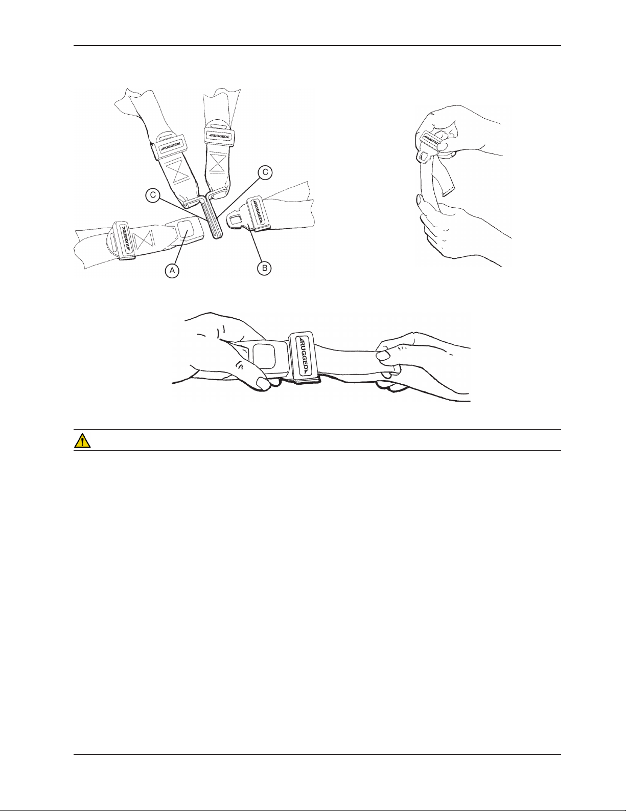
Figure 17 - Buckling the Safety Restraints
Figure 19 - Shortening the Safety Restraint
Figure 18 - Lengthening the Safety Restraint
CAUTION
Ensure that restraints are not entangled in the base frame when raising and lowering the cot.
When the cot is put into service, open the restraints and place them at either side of the cot until the patient is
positioned on the cot mattress. Lengthen the restraints, buckle them around the patient and shorten them until the
required tightness is achieved.
• Toopentherestraint,presstheredbutton(A)onthefrontofthebuckle“receiver”.Thisreleasesthebuckle“tang”
(B) which can then be pulled out of the receiver (Figure 17).
• Toclosetherestraint,pushthetangintothereceiveruntila“click”isheard.Whenfasteningthechestrestraint
ensure the tang passes through both links (C) on the shoulder strap (Figure 17).
• Tolengthentherestraint,graspthebuckletang,turnitatanangletothewebbing,thenpullitout(Figure18).A
hemmed tab at the end of the webbing prevents the tang from coming off the strap.
• Toshorten the restraint,graspthehemmed tab and pull the webbing backthroughthetanguntil the required
tightness is achieved (Figure 19).
Whenever a restraint is buckled on a patient, verify the tang is fully engaged and any extra webbing is not tangled in
the cot or hanging loose.
Inspection of the restraints should be done at least once a month (more frequently if used heavily). Inspection should
include checking for a bent or broken receiver or tang, torn or frayed webbing, etc. Any restraint showing wear or not
operating properly must be replaced immediately.
Return To Table of Contents
www.stryker.com 650 0- 309 -0 01 REV A 29
Page 30
Cot Features
USING THE RESTRAINT BELT EXTENSION (OPTIONAL)
Figure 20 - Attaching the Restraint Belt Extension
Use the restraint belt extension for extra length when buckling the lap belt around large patients.
Return To Table of Contents
30 65 00-30 9- 001 RE V A www.stryker.com
Page 31

Cot Features
PEDI-MATE™ INFANT RESTRAINT SYSTEM (OPTIONAL) ATTACHMENT INSTRUCTIONS
Refer to the Pedi-Mate™ users manual for the manufacturer’s recommendations for the use, operation and care of the
Pedi-Mate™ Infant Restraint System.
Securing the Pedi-Mate™ to the cot:
1. Remove any restraints already attached to the cot.
2. Raise the cot backrest to the full upright position.
3. Position the Pedi-Mate™ pad flat on the backrest with the black backrest straps out (see Figure 21).
Figure 21 - Positioning the Pedi-Mate™
4. Wrap the straps around the backrest and insert the ends of the straps through the brackets. Securely fasten the
buckle (see Figure 22).
Figure 22 - Fastening the Pedi-Mate™ Buckle
WARNING
To avoid accidental release of the Pedi-Mate™, and possible injury to the infant, ensure the buckle is located away from
obstructions on the cot or accessories.
Return To Table of Contents
www.stryker.com 650 0- 309 -0 01 REV A 31
Page 32

Cot Features
PEDI-MATE™ INFANT RESTRAINT SYSTEM ATTACHMENT INSTRUCTIONS (CONTINUED)
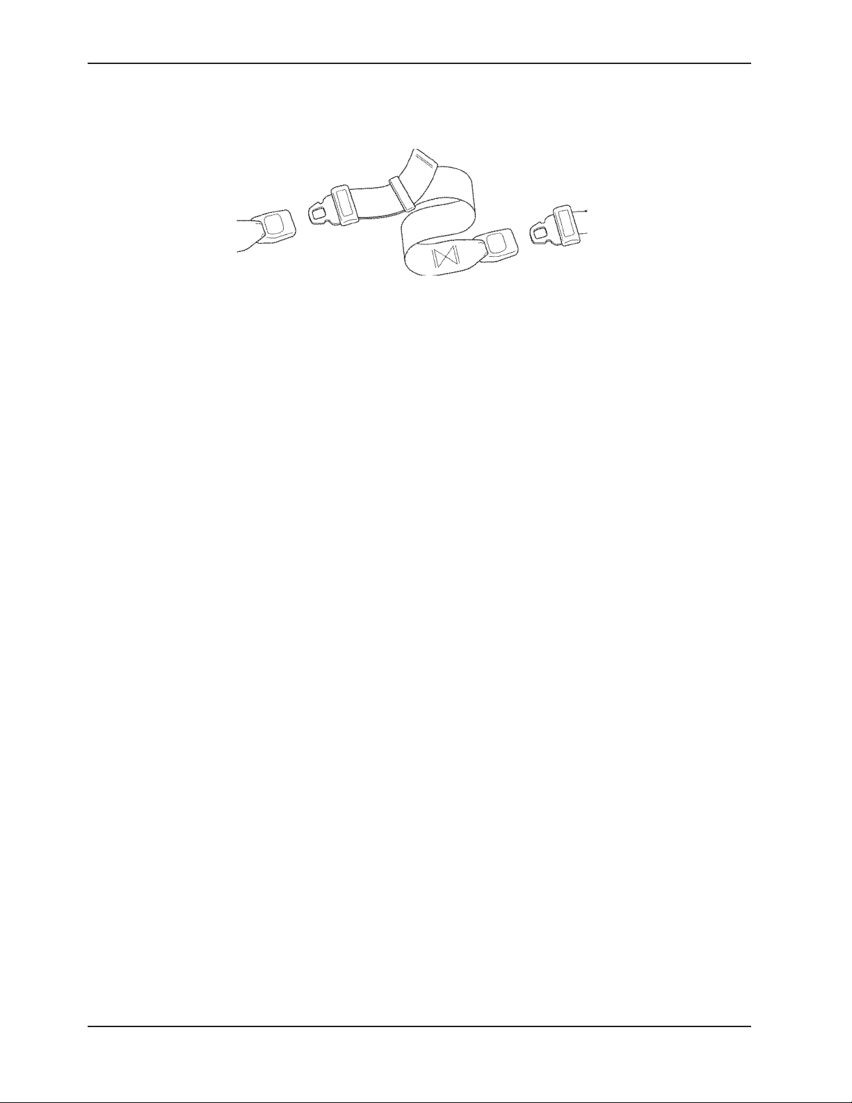
5. Pull firmly on the end of the adjustable backrest strap and tighten it securely.
6. Insert the mainframe straps between the cot frame and the mattress. To ensure the release button is toward
the foot end of the cot, insert the buckle behind the litter cross brace and bring it up in front of the cross brace.
Figure 23 - Securing the Safety Restraints on a Cot
Secure the buckle around the crossbrace, leaving a little slack in the strap for final adjustment (see Figure 23).
WARNING
To avoid accidental release of the Pedi-Mate™, and possible injury to the infant, ensure the buckle is located away
from obstructions on the cot.
Figure 24- Pedi-Mate™ Strapped to a Cot
7. Verify all the straps are snug and fastened securely (see Figure 24).
NOTE
These are general instructions for installation of the Pedi-Mate™. Safe and proper use of the Pedi-Mate™ is solely at
the discretion of the user. Stryker recommends all users be trained on the proper use of the Pedi-Mate™ before using
it in an actual situation.
Retain these instructions for future reference. Include them with the product in the event of transfer to new users.
Pedi-Mate™ is a trademark of Ferno-Washington Inc.
Return To Table of Contents
32 6 500 -309-001 REV A www.stryker.com
Page 33

Cot Features
OPERATING THE OPTIONAL WHEEL LOCK(S)
Figure 25 - Wheel Lock
1. To activate the optional wheel lock(s), press fully down on the pedal (A) until it stops and is resting firmly against
the surface of the wheel.
2. To release the optional wheel lock(s), depress the upper face of the pedal with your foot or lift up with your
toe under the pedal. The upper portion of the pedal will rest against the caster frame when the wheel lock is
released.
WARNING
Never apply the optional wheel lock(s) while a patient is on the cot. Tipping could occur if the cot is moved while a
wheel lock is applied, resulting in injury to the patient or operator and/or damage to the cot.
Never leave a patient unattended on the cot or injury could result. Hold the cot securely while a patient is on the cot.
Never install or use a wheel lock on a cot with excessively worn wheels. Installing or using a wheel lock on a wheel with
less than a 6" diameter could compromise the holding ability of the wheel lock, possibly resulting in injury to the patient
or operator and/or damage to the cot or other equipment.
CAUTION
Wheel lock(s) are only intended to help prevent the cot from rolling while unattended. A wheel lock may not provide
sufficient resistance on all surfaces or under loads.
Return To Table of Contents
www.stryker.com 650 0- 309 -0 01 REV A 33
Page 34

Cot Features
ADJUSTING THE WHEEL LOCKING FORCE
MINIMUM
1. To adjust the wheel locking force, remove the socket screw from the center of the lock pedal. The wheel lock is
initially assembled with the pedal set at the minimum locking force. The marker on the pedal (item A) is aligned
with the marker on the octagonal sleeve (item B).
2. Remove the sleeve (B). Rotate the sleeve counterclockwise to increase the pedal locking force and clockwise to
decrease the locking force. Insert the sleeve into the pedal. Reinstall the socket screw.
3. Test the pedal locking force and verify the pedal holds properly before returning the cot to service.
Figure 26 - Wheel Locking Force Adjustment
MAXIMUM
ADJUSTING THE COT RETAINING POST
Retaining Post
Arrow
Bottom Bracket
Figure 27 - Cot Retaining Post
Bottom View
CAUTION
The ambulance cot fastener comes preconfigured for an X-Frame cot, if the fastener has been configured for an Hframe style cot, the cot retaining post must be adjusted to accommodate the fastener.
1. Remove the bolts holding the two retaining post brackets to the base frame.
2. Turn the bottom bracket 180˚.
3. Reinstall the bolts.
NOTE
If the arrow on the bottom bracket of the retaining post points toward the head end of the cot, the retaining post is
set for an X-frame style cot. If the arrow points toward the foot end of the cot the post is set for an H-frame style cot.
Return To Table of Contents
34 6500 -309- 001 REV A www.stryker.com
Page 35

ADJUSTING THE FOOTREST
Cot Features
FOOT END
Figure 28 - Footrest Elevated
The footrest is adjustable to allow for elevation of the patient’s legs.
To raise the footrest, lift the foot rest frame (A) as high as possible. The support bracket will engage automatically
when released.
To lower the footrest, lift the foot rest frame (A) and, while holding the frame, lift up on the release handle (B) until the
bracket disengages. Lower the footrest until flat.
Return To Table of Contents
www.stryker.com 650 0- 309 -0 01 REV A 35
Page 36

HEAD END
Cot Features
Figure 29 - Backrest Elevated and Siderails Raised
OPERATING THE BACKREST
To raise, squeeze handle (A) for pneumatic assist in lifting the backrest to the desired height.
To lower, squeeze handle (A) and push down on the backrest frame until the backrest has reached the desired
height.
OPERATING THE SIDERAILS
To raise, lift up until the latch clicks and the siderail locks into place. When a patient is on the cot, always keep the
siderails in the raised position unless the patient is being transferred.
To lower, squeeze handle (B) to release the siderail latch. Guide the siderail down toward the foot end until flat.
WARNING
Siderails are not intended to serve as a patient restraint device. Refer to pages 24 and 25 for proper restraint strap
usage. Failure to utilize the siderails properly could result in patient injury.
Return To Table of Contents
36 6500 -30 9- 001 RE V A w ww.stryker.com
Page 37

BATTERY POWER INDICATOR
Cot Features
Figure 30a - Battery Power Indicator
To check the battery power level, depress lightly on the retract (–) switch (A) to activate the battery power indicator
light (B). The battery power indicator is located at the foot-end control enclosure, represented by a battery icon.
• The indicator lights GREEN when the battery is fully charged or has adequately charged battery power.
• TheindicatordisplaysREDwhenthebatteryneedstoberechargedorreplaced.
Figure 30b - Retract Switches
WARNING
To avoid risk of electric shock, never attempt to open the battery pack for any reason. If the battery pack case •
is cracked or damaged, do not insert it into the charger. Return damaged battery packs to a service center for
recycling.
Do • not remove the battery when the ambulance cot is activated.
Avo• id contact with a wet battery or battery enclosure. Contact may cause injury to the patient or operator.
CAUTION
Only use the battery and charger as specified.•
The • Power-PRO™ XT ambulance cot is not for use with an AC adapter.
Wh• en charging batteries in an ambulance vehicle, locate the charger either in the forward cab or an enclosed
compartment (i.e. cabinet).
E• nsure that the battery is fully charged prior to placing into service. An uncharged or depleted battery may cause
poor ambulance cot performance.
Ref• er to the DeWA LT® manual (Stryker part number 6500-001-206) for battery and charger information.
Return To Table of Contents
www.stryker.com 650 0- 309 -0 01 REV A 37
Page 38

HOUR METER
Cot Features
Figure 31 - Usage Meter
The cot has an hour meter on the foot-end control enclosure that indicates the amount of time (HHH.H hours) that
the hydraulics have been activated. The hour meter can be used to help determine the frequency for preventative
maintenance procedures found on pages 58-61.
CAUTION
A preventative maintenance program should be established for all Stryker EMS equipment. Preventative maintenance •
may need to be performed more frequently based on the usage level of the product. Close attention should be
given to safety features including, but not limited to:
Hydraulic power mechanism•
All electrical controls return to off or neutral position when released•
For additional maintenance information, refer to the preventative maintenance section (pages 58-61).•
Return To Table of Contents
38 65 00-30 9- 001 RE V A www.stryker.com
Page 39

Cot Features
INSTALLING THE OPTIONAL HEAD END STORAGE FLAT
Crossbar
V-Tube
Figure 32 - Head End Storage Flat
1. Install the Velcro® straps (A) across the V-Tube near the pneumatic cylinder and around the crossbar of the retractable head section.
2. Buckle the restraint straps (B) around the outer rails of the retractable head section.
WARNING
When the optional head-end storage flat is being used, ensure it does not interfere with the operation of the retractable
head section, safety bar and safety hook. Injury to the patient or operator could result.
CAUTION
Do not store items under the ambulance cot mattress. Storing items under the mattress can interfere with the operation
of the ambulance cot.
The weight of the equipment in the head end storage flat (if equipped) must not exceed 40 pounds (18 kg).
Return To Table of Contents
www.stryker.com 650 0- 309 -0 01 REV A 39
Page 40

Cot Features
INSTALLING THE OPTIONAL BACKREST STORAGE POUCH
Figure 33 - Backrest Storage Pouch
Install the optional backrest storage pouch using the Velcro® straps. Insert each strap through a hole in the backrest
skin and mount the pouch flat against the backrest.
CAUTION
Do not store items under the ambulance cot mattress. Storing items under the mattress can interfere with the •
operation of the ambulance cot.
The• weight of the equipment in the pocketed backrest storage pouch (if equipped) must not exceed 20 pounds
(9 kilograms).
Return To Table of Contents
40 6500-309- 001 REV A www.stryker.com
Page 41

Cot Features
USING THE OPTIONAL EQUIPMENT HOOK
Equipment Hook
Figure 34 - Equipment Hook
The equipment hook is used to hang additional accessories or equipment such as defibrillators or monitors.
CAUTION
To avoid damage to the equipment hook, the weight of the accessories or equipment must not exceed 20 pounds
(9 kilograms).
Return To Table of Contents
www.stryker.com 650 0- 309 -0 01 REV A 41
Page 42

Cot Features
OPERATING THE 2-STAGE I.V. POLE (OPTIONAL EQUIPMENT)
Figure 35 - 2-Stage I.V. Pole Storage Position
C
D
B
A
Figure 36 - 2-Stage I.V. Pole
1. Lift and pivot the pole from the storage position and push down until it is locked into receptacle (A).
2. To raise the height of the pole, turn the lock actuator (B) counterclockwise and pull up on the telescoping portion
(C) of the pole to raise it to the desired height.
3. Turn the lock actuator (B) clockwise to lock the telescoping portion in place.
4. Hang the I.V. bags on the I.V. hook (D).
CAUTION
To avoid damage to the I.V. pole, the weight of the I.V. bags or equipment must not exceed 40 pounds (18kg).
5. Turn the lock actuator (B) counterclockwise and slide section (C) into the bottom tube.
6. Lift up and pivot the pole down into the storage position.
Return To Table of Contents
42 6500 -309- 001 REV A www.stryker.com
Page 43

Cot Features
A
B
C
D
E
F
OPERATING THE 3-STAGE I.V. POLE (OPTIONAL EQUIPMENT)
1. Lift and pivot the pole from the storage position and push down
until it is locked into receptacle (A).
2. To raise the height of the pole, turn the lock actuator (B)
counterclockwise and pull up on the bottom telescoping portion
(C) of the pole to raise it to the desired height.
3. Turn the lock actuator (B) clockwise to lock the bottom telescoping
portion in place.
4. For a higher I.V. pole, pull up on section (D) until the spring clip
(E) engages.
5. Hang I.V. bags on the I.V. hook (F).
CAUTION
To avoid damage to the I.V. pole, the weight of the I.V. bags or equipment must not exceed 40 pounds (18 kilograms).
6. To lower the I.V. pole, push in on the spring clip (E) and slide
section (D) down into section (C). Turn the lock actuator (B)
counterclockwise and slide section (C) into the bottom tube.
7. Lift up and pivot the pole down into the storage position.
Figure 37 - 3-Stage I.V. Pole Storage Position
Figure 38 - 3-Stage I.V. Pole
www.stryker.com 650 0- 309 -0 01 REV A 43
Return To Table of Contents
Page 44

Cot Operation
OPERATING GUIDELINES
• Usethecotonlyasdescribedinthismanual.
• Readalllabelsandinstructionsonthecotbeforeusingthecot.
• Useaminimumoftwo(2)operatorstomanipulatethecotwhileapatientisonthecot.Ifadditionalassistanceis
needed, see the reference chart on page 55.
• Donotadjust,rollorloadthecotintoavehiclewithoutadvisingthepatient.Staywiththepatientandcontrolthe
cot at all times.
• Theambulancecotcanbetransportedinanyposition.Strykerrecommendstransportingthepatientinaslowa
position as is comfortable for the operators to maneuver the cot.
• Onlyusethewheellock(s)duringpatienttransferorwithoutapatientontheambulancecot.
• Alwaysusetherestraintstraps.
• Useproperlytrainedhelperswhennecessarytocontrolthecotandpatient.
WARNING
Improper usage of the Power-PRO™ XT ambulance cot can cause injury to the patient or operator. Operate the •
ambulance cot only as described in this manual.
Entanglement in powered ambulance cot mechanisms can cause serious injury. Operate the ambulance cot only •
when all persons are clear of the mechanisms.
Practice changing height positions and loading the ambulance cot until operation of the product is fully understood. •
Improper use can cause injury.
Do not allow untrained assistants to assist in the operation of the ambulance cot. Untrained technicians/assistants •
can cause injury to the patient or themselves.
Ensure proper hand placement on hand grips. Hands should be clear of red safety bar pivots while loading and •
unloading the cot.
Do not ride on the base of the Power-PRO™ XT ambulance cot. Damage to the product could occur, resulting in •
injury to the patient or operator.
Transporting the cot sideways can cause the cot to tip, resulting in possible damage to the product and/or injury to the •
patient or operator. Transporting the cot in a lowered position, head or foot end first, will minimize the potential of a cot
tip.
Grasping the Power-PRO™ XT ambulance cot improperly can cause injury. Keep hands, fingers and feet away •
from moving parts. To avoid injury, use extreme caution when placing your hands and feet near the base tubes
while raising and lowering the ambulance cot.
Any emergency vehicle to be used with this ambulance cot • must have the in-fastener shut-off system installed.
CAUTION
Before operating the cot, clear any obstacles that may interfere and cause injury to the operator or patient.
PROPER LIFTING TECHNIQUES
When lifting the ambulance cot and patient, there are five basic guidelines to help you avoid injury:
Ke• ep your hands close to your body.
Keep your back straight.•
Coordinate your movements with your partner and lift with your legs.•
Avoid twisting.•
Always operate the ambulance cot as described in this manual.•
Return To Table of Contents
44 65 00-30 9- 001 RE V A www.stryker.com
Page 45

Cot Operation
TRANSFERRING THE PATIENT TO THE COT
Roll the cot to the patient.1.
Pl2. ace the cot beside the patient and raise/lower the cot to the level of the patient.
Lo3. wer the siderails and open the restraint straps.
Tran4. sfer the patient to the cot using accepted EMS procedures.
Us5. e all the restraint straps to secure the patient to the cot (see pages 19 and 20 for usage instructions).
Ra6. ise the siderails and adjust the backrest and leg rest as necessary.
WARNING
Always use all restraint straps to secure the patient on the cot. An unrestrained patient may fall from the cot and •
be injured.
Ne• ver leave a patient unattended on the ambulance cot or injury could result. Hold the ambulance cot securely
while a patient is on the product.
Neve• r apply the optional wheel lock(s) while a patient is on the cot. Tipping could occur if the cot is moved while
the wheel lock is applied, resulting in injury to the patient or operator and/or damage to the cot.
Side• rails are not intended to serve as a patient restraint device. Refer to pages 24 and 25 for proper restraint strap
usage. Failure to utilize the siderails properly could result in patient injury.
Hydr• aulically raising or lowering the cot may temporarily affect electronic patient monitoring equipment. For best
results, patient monitoring be conducted when the cot is idle.
USING THE OPTIONAL TRANSFER FLAT
When transferring large patients, use of the Transfer Flat (Stryker part number 6083-001-200) is recommended.
AMBULANCE COT MOTION
Make sure all the restraint straps are securely buckled around the patient (see page 19 & 20 for restraint strap 1.
usage instructions).
Th2. e cot can be in any position for rolling.
When rolling the cot with a patient on it, position an operator at the foot end and one at the head end of the cot 3.
at all times.
Duri4. ng transport, approach door sills and/or other low obstacles squarely and lift each set of wheels over the
obstacle separately.
WARNING
High obstacles such as curbing, steps or rough terrain can cause the ambulance cot to tip, possibly causing injury to
the patient or operator. Transporting the cot in lower positions can reduce the potential of a cot tip. If possible, obtain
additional assistance (see page 55 for a reference chart) or take an alternate route.
CAUTION
The ambulance cot can be set at any height position. Establish the required load height for the ambulance cot prior to
placing the unit into service (reference page 18 for instructions).
Return To Table of Contents
www.stryker.com 650 0- 309 -0 01 REV A 45
Page 46

Cot Operation
LOADING THE COT INTO A VEHICLE WITH TWO OPERATORS - POWERED METHOD
WARNING
Ensure proper hand placement on hand grips. Hands
should be clear of red safety bar pivots while loading and
unloading the cot.
Loading an occupied cot into the vehicle requires a minimum
of two (2) trained operators.
When loading the cot into a vehicle, an operator should
remember the following important issues:
• Theremustbeasafetyhookproperlyinstalledinthe
vehicle so that the bumper does not interfere with the
front legs of the base frame. (See page 24 for safety
hook installation instructions.)
WARNING
Failure to install and use the vehicle safety hook can result
in injury to the patient or operator. Install and use the hook
as described in this manual.
Figure 39 - Safety Bar Engaging Safety Hook
• Cotoperatorsmustbeabletoliftthetotalweightofthe
patient, cot and any items on the cot. The higher an
operator must lift the cot, the more difficult it becomes
to hold the weight. An operator may need help loading
the cot if he/she is small or if the patient is too large to
lift safely.
CAUTION
Loading, unloading or changing the position of a loaded
ambulance cot requires a minimum of two trained
operators. The operator(s) must be able to lift the total
weight of the patient, cot and any other items on the cot
(if additional assistance is needed, see page 55 for a
reference chart).
Place the cot in a loading position (any position where the
loading wheels meet the vehicle floor height). Roll the cot
to the open patient compartment. Lift the vehicle bumper
to the raised position (if possible).
Push the cot forward until the load wheels are on the
patient compartment floor and the safety bar passes the
safety hook (Figure 39).
For maximum clearance to lift the base, pull the cot back
until the safety bar engages the safety hook. Operator two
should verify that the bar engages the safety hook.
Operator 1 - Grasp the cot frame at the foot end and push
the retract (–) button until the undercarriage of the cot
retracts fully (Figure 40).
Operator 2 - Securely grasp the cot outer rail to stabilize
the cot during retraction.
Both Operators - Push the cot into the patient compartment
(Figure 41), until the cot engages the cot fastener (not
included).
Return To Table of Contents
46 6500-309- 001 REV A www.stryker.com
Figure 40 - 2 Operators - One Pushing the Retract
Button
Figure 41 - 2 Operators Loading the Cot
Page 47

Cot Operation
LOADING THE COT INTO A VEHICLE WITH TWO OPERATORS - POWERED METHOD (CONTINUED)
WARNING
When using a standard ambulance cot fastener, do not load the cot into the vehicle with the head section retracted.
Loading the cot with the head section retracted may cause the product to tip or not engage properly in the cot fastener,
possibly causing injury to the patient or operator and/or damage to the cot.
HIGH SPEED RETRACT/EXTEND
• Theambulancecotisequippedwithahigh-speedretractmodetoexpediteloading/unloadingthecotintoandout
of a vehicle.
• The undercarriagerapidly retracts towards its uppermost position once the weight of the ambulance cot and
patient is off the wheels. Press the retract (–) button to actuate the control switch.
• The undercarriagerapidly extends towards its lowermost position once the weight of the ambulance cot and
patient is off the wheels. Press the extend (+) button to actuate the control switch.
WARNING
Whenever the weight of the ambulance cot and patient is off the wheels, the ambulance cot will automatically enter
the high speed retract mode if the retract (–) button is pressed.
Once the weight is off the ground, the operator(s) must support the load of the patient, ambulance cot and any
accessories. Failure to support the load properly may cause injury to the patient or operator.
LOADING THE COT INTO A VEHICLE WITH TWO OPERATORS AT THE FOOT END
WARNING
Ensure proper hand placement on hand grips. Hands should be clear of red safety bar pivots while loading and
unloading the cot.
Place the cot in a loading position (any position where the loading wheels meet the vehicle floor height). Roll the 1.
cot to the open patient compartment. Lift the vehicle bumper to the raised position (if possible).
Pu2. sh the cot forward until the load wheels are on the patient compartment floor and the safety bar passes the
safety hook.
For3. maximum clearance to lift the base, pull the cot back until the safety bar engages the safety hook. One
operator should remain at the foot end while the second operator engages the safety hook as described above.
The4. second operator should return to the foot end and both operators should lift the cot while one operator pushes
the retract (–) button until the undercarriage of the cot retracts fully.
Both5. operators should push the cot into the patient compartment, until the cot engages the cot fastener (not
included).
Return To Table of Contents
www.stryker.com 650 0- 309 -0 01 REV A 47
Page 48

Cot Operation
LOADING AN EMPTY COT INTO A VEHICLE WITH ONE OPERATOR - POWERED METHOD
WARNING
Ensure proper hand placement on hand grips. Hands
should be clear of red safety bar pivots while loading and
unloading the cot.
Loading an unoccupied cot into the emergency vehicle
can be accomplished by a single operator.
WARNING
The one person loading and unloading procedures are for
use only with an empty ambulance cot. Do not use the
procedures when loading/unloading a patient. Injury to the
patient or operator could result.
Place the ambulance cot into a loading position (any 1.
position where the load wheels of the head section
meet the vehicle floor height).
Roll the ambulance cot to the open door of the patient 2.
compartment.
Lift the vehicle bumper to the raised position (if 3.
possible).
Push the ambulance cot forward until the load wheels 4.
are on the patient compartment floor and the safety
bar passes the safety hook.
For 5. maximum clearance to lift the base, pull the ambulance cot until the safety bar engages the safety hook
(Figure 39). Operator two should verify that the bar
engages the safety hook.
Gr6. asp the ambulance cot frame at the foot-end and
press the retract (–) button, until the undercarriage of
the ambulance cot retracts into its uppermost position
(Figure 43).
Pus7. h the ambulance cot into the patient compartment
until the ambulance cot engages the cot fastener (not
included).
WARNING
Figure 42 - Load Wheels on the Vehicle Floor
Figure 43 - Push the Retract Button
When using a standard ambulance cot fastener, do not load
the cot into the vehicle with the head section retracted.
Loading the cot with the head section retracted may cause
the product to tip or not engage properly in the cot fastener,
possibly causing injury to the patient or operator and/or
damage to the cot.
Figure 44 - Push the Cot into the Vehicle
Return To Table of Contents
48 6500- 309-001 REV A ww w.stryker.com
Page 49

Cot Operation
UNLOADING THE COT FROM A VEHICLE WITH TWO OPERATORS - POWERED METHOD
Unloading the cot from the vehicle while a patient is
on the cot requires a minimum of two (2) operators,
positioned at each end of the ambulance cot. Each
operator must grasp the ambulance cot frame securely.
Disengage the cot from the cot fastener (For more
detailed instructions, reference the ambulance cot
fastener installation/operation manual - Stryker part
number 6370-090-010).
Lift the vehicle bumper to the raised position (if
possible).
WARNING
Do not press the extend (+) button until the safety bar
engages the safety hook.
Operator 1 - Grasp the ambulance cot frame at the foot
end. Pull the cot out of the patient compartment until
the safety bar engages the safety hook. Operator two
should verify that the bar engages the safety hook.
WARNING
To avoid injury, verify the safety bar has engaged the
safety hook before removing the ambulance cot from the
patient compartment.
Operator 2 - Stabilize the cot during the unloading operation by securely grasping the outer rail.
Operator 1 - Depress the extend (+) button to lower the
undercarriage to its fully extended position (Figure 46).
Operator 2 - Push the safety bar release lever forward
to disengage the safety bar from the safety hook in the
patient compartment (Figure 47).
WARNING
Figure 45 - 2 Operators Unloading the Cot
Figure 46 - 2 Operators - One Pushing the Extend
Button
Do not pull or lift on the safety bar when unloading the
cot. Damage to the safety bar could result and injury to
the patient or operator could occur.
Remove the load wheels from the patient compartment
of the vehicle.
CAUTION
When unloading the cot from the patient compart-•
ment, ensure the caster wheels are safely set on
the ground or damage to the product may occur.
Do not “jog” the cot past the load height while the •
safety bar is engaged.
Unloading an • unoccupied ambulance cot from a
vehicle can be accomplished by a single operator.
www.stryker.com 650 0- 309 -0 01 REV A 49
Figure 47 - Disengaging the Safety Bar
Return To Table of Contents
Page 50

Cot Operation
UNLOADING THE COT FROM A VEHICLE WITH ONE OPERATOR - POWERED METHOD
WARNING
Ensure proper hand placement on hand grips. Hands should
be clear of red safety bar pivots while loading and unloading
the cot.
WARNING
The one person loading and unloading procedures are for
use only with an empty ambulance cot. Do not use the
procedures when unloading a patient. Injury to the patient or
operator could result.
Disengage the cot from the cot fastener (For more detailed instructions, reference the ambulance cot fastener installation/
operation manual - Stryker part number 6370-090-010).
Lift the vehicle bumper to the raised position (if possible).
Grasp the cot frame at the foot end. Pull the cot out of the
patient compartment until the safety bar engages the safety
hook. Operator two should verify that the bar engages the
safety hook.
Figure 48 - Pull the Cot out of the Vehicle
WARNING
Do not pull or lift on the safety bar when unloading the cot.
Damage to the safety bar could result and injury to the patient
or operator could occur.
Depress the extend (+) button to lower the undercarriage to
its fully extended position (Figure 48).
Push the safety bar release lever forward to disengage the
safety bar from the safety hook in the patient compartment.
Remove the load wheels from the patient compartment of
the vehicle.
CAUTION
When unloading the ambulance cot from the patient
compartment, ensure the caster wheels are safely set on
the ground or damage to the product may occur.
Do not “jog” the cot past the load height while the safety
bar is engaged.
Figure 49 - Push the Extend Button
Figure 50 - Remove Load Wheels from the
Vehicle Floor
Return To Table of Contents
50 6500 -30 9- 001 RE V A w ww.stryker.com
Page 51

MANUAL OVERRIDE OPERATION
Cot Operation
Figure 51 - Manual Release Handle
In the event of loss of electrical function, the ambulance cot is equipped with a manual override to allow manual operation of the product until electrical functionality is restored.
The red manual release lever (A) is located along the patient left side of the lower lift bar at the foot end of the cot.
To raise or lower the cot with the manual release:
Both Operators - lift the cot during the raise/lower operation to support the weight of the cot.
With the ambulance cot supported by an operator at each end, the operator at the foot-end must pull the release
handle towards the lift bar. While the release handle is pulled, raise or lower the ambulance cot to the desired position
and then release the handle to lock ambulance cot into position.
NOTE
The operators must lift the cot weight slightly off the wheels to use the manual extend or retract while a patient •
is on the cot.
Activ• ation of the manual release may cause the ambulance cot to drop slowly if less than 40 pounds (18 kg) are
on the cot, which may cause injury to the patient or operator.
Return To Table of Contents
www.stryker.com 650 0- 309 -0 01 REV A 51
Page 52

Cot Operation
LOADING THE COT INTO A VEHICLE WITH TWO OPERATORS - MANUAL METHOD
WARNING
Ensure proper hand placement on hand grips. Hands
should be clear of red safety bar pivots while loading
and unloading the cot.
To load the cot with the manual release:
Place the cot in a loading position (any position where
the loading wheels meet the vehicle floor height). Roll
the cot to the open door of the patient compartment. Lift
the vehicle bumper to the raised position (if possible).
Push the cot forward until the loading wheels are on the
patient compartment floor and the safety bar passes the
safety hook.
For maximum clearance to lift the base, pull the cot back
until the safety bar engages the safety hook.
Operator 1 - Grasp the cot frame at the foot end. Lift
the foot end of the cot until the weight is off the latching
mechanism. Squeeze and hold the release handle.
Figure 52 - Manual Release Lever
Operator 2 - Stabilize the cot by placing your hand on
the outer rail. Grasp the base frame. After the foot end
operator has lifted the cot and squeezed the release
handle, raise the undercarriage until it stops in the
uppermost position and hold it there.
Both Operators - Push the cot into the patient
compartment, engaging the cot fastener (not included).
NOTE
When operating the manual release, avoid rapid lifting or
lowering of the base or movement may appear sluggish;
lift with a slow constant motion.
Figure 53 - 2 Operators - One Lifting the Base
Figure 54 - Push the Cot into the Vehicle
Return To Table of Contents
52 6 500 -3 09-001 REV A www.stryker.com
Page 53

Cot Operation
UNLOADING THE COT FROM A VEHICLE WITH TWO OPERATORS - MANUAL METHOD
WARNING
Ensure proper hand placement on hand grips. Hands
should be clear of red safety bar pivots while loading and
unloading the cot.
Unloading the cot from the vehicle while a patient is on the
cot requires a minimum of two (2) operators, positioned
at each end of the ambulance cot. Each operator must
grasp the ambulance cot frame securely.
Disengage the cot from the cot fastener (For more
detailed instructions, reference the ambulance cot
fastener installation/operation manual - Stryker part
number 6370-090-010).
Lift the vehicle bumper to the raised position (if
equipped).
Figure 55 - 2 Operators Unloading the Cot
Operator 1 - Grasp the ambulance cot frame at the
foot end. Pull the manual release lever to lower the
undercarriage to its fully extended position (Figure 50).
Pull the cot out of the patient compartment until the
safety bar engages the safety hook. Operator two should
verify that the bar engages the safety hook.
WARNING
To avoid injury, verify the safety bar has engaged the
safety hook before removing the ambulance cot from the
patient compartment.
Operator 2 - Stabilize the cot during the unloading
operation by securely grasping the outer rail.
Operator 2 - Push the safety bar release lever forward
to disengage the safety bar from the safety hook in the
patient compartment (Figure 57).
WARNING
Do not pull or lift on the safety bar when unloading the
cot. Damage to the safety bar could result and injury to
the patient or operator could occur.
Figure 56 - 2 Operators - One Pushing the Extend
Button
Remove the load wheels from the patient compartment
of the vehicle.
Figure 57 - Disengaging the Safety Bar
CAUTION
When unloading the cot from the patient compartment,
ensure the caster wheels are safely set on the ground or
damage to the product may occur.
Return To Table of Contents
www.stryker.com 650 0- 309 -0 01 REV A 53
Page 54

Cot Operation
UNLOADING AN EMPTY COT FROM A VEHICLE WITH ONE OPERATOR - MANUAL METHOD
WARNING
Ensure proper hand placement on hand grips. Hands
should be clear of red safety bar pivots while loading and
unloading the cot.
Unloading an unoccupied ambulance cot from a vehicle
can be accomplished by a single operator.
WARNING
The one person loading and unloading procedures are for
use only with an empty ambulance cot. Do not use the
procedures when unloading a patient. Injury to the patient
or operator could result.
Disengage the cot from the cot fastener (For more detailed
instructions, reference the ambulance cot fastener
installation/operation manual - Stryker part number
6370-090-010).
Figure 58 - Pull the Cot out of the Vehicle
Lift the vehicle bumper to the raised position (if possible).
Grasp the cot frame at the foot end. Pull the manual
release lever to lower the undercarriage to its fully
extended position (Figure 59). Pull the cot out of the patient
compartment until the safety bar engages the safety hook.
Operator two should verify that the bar engages the safety
hook.
Push the safety bar release lever forward to disengage
the safety bar from the safety hook in the patient
compartment.
WARNING
Do not pull or lift on the safety bar when unloading the cot.
Damage to the safety bar could result and injury to the
patient or operator could occur.
Remove the load wheels from the patient compartment of
the vehicle.
CAUTION
When unloading the ambulance cot from the patient
compartment, ensure the caster wheels are safely set on
the ground or damage to the product may occur.
Figure 59 - Pull the Manual Release Lever
Hydraulic fluid will become more viscous when the PowerPRO™ XT is used for extended periods in cold temperatures.
When using the manual release function to extend the
base during unloading in cold weather conditions, hold
the release lever engaged for approximately one second
after the cot wheels touch the ground to minimize sagging
of the litter as the cot is removed from the ambulance.
Return To Table of Contents
54 6500 -309- 001 REV A www.stryker.com
Figure 60 - Remove Load Wheels from the Vehicle
Floor
Page 55

Cot Operation
ADJUSTING COT HEIGHT
Changing height of the cot while a patient is on the cot requires a minimum of two (2) operators, positioned at each
end of the ambulance cot.
Operator 1 - Grasp the ambulance cot frame at the foot-end. Actuate the control switch, depress either the (+) or (–)
button depending on desired travel direction, and allow the litter to raise/lower to the desired position.
Operator 2 - Maintain a firm grip on the outer rail until the ambulance cot is securely in position.
WARNING
Grasping the ambulance cot improperly can cause injury. Keep hands, fingers and feet away from moving parts. To
avoid injury, use extreme caution when placing your hands and feet near the base tubes while raising and lowering the
ambulance cot.
NOTE
If the push button switch remains activated, the motor will remain halted until the operator releases the button. Once
the push button is released, actuate the extend (+) button again to “jog” the cot height up further.
CAUTION
Do not “jog” the ambulance cot past the established load height of the product when the safety bar engages the vehicle
safety hook or damage may occur to the product.
USING ADDITIONAL ASSISTANCE
Changing Levels Rolling Loading/Unloading
Helper
Helper
Helper Helper
Helper
Operator
Operator
Helper
Operator
Helper
Helper
Operator
Helper
Operator
Helper
Helper
Operator
Two
Operators
Two
Helpers
Two
Operators
Four
Helpers
Helper
Operator
Helper
Operator
Helper
Helper
Operator
Helper
Operator
Helper
Operator
Helper
Operator
Return To Table of Contents
www.stryker.com 650 0- 309 -0 01 REV A 55
Page 56

Cot Operation
OPERATING THE RETRACTABLE HEAD SECTION
The head section telescopes from a first position suitable
for loading the ambulance cot into an emergency vehicle
to a second position retracted within the litter frame. When
retracted, the ambulance cot can roll in any direction on the
caster wheels even in the lowest position, allowing improved
mobility and maneuverability.
To extend the head section:
• Grasptheouterrailwithonehandforsupportandrelease
the lever (A), rotate the lever towards the head end of the
cot to release the head section from the locked position.
• Whileholdingthehandle(A)inthereleasedposition,pull
the head section away from the litter frame, lengthening
the head section until it engages in the fully extended
position.
To retract the head section:
• Grasptheouterrailwithonehandforsupportandrelease
the lever (A), rotate the lever towards the head end of the
cot to release the head section from the locked position.
• Whileholdingthehandle(A)inthereleasedposition,push
the head section toward the litter frame, retracting the
head section until it engages in the retracted position.
Figure 61 - Head Section Extended
WARNING
To avoid injury, always verify that the head section is locked
into place prior to operating the ambulance cot.
When using a standard ambulance cot fastener, do not attempt
to load the ambulance cot into the patient compartment with
the head section retracted. Loading the ambulance cot with
the head section retracted may cause the product to tip or not
engage properly in the cot fastener, possibly causing injury to
the patient or operator and/or damage to the product.
Figure 62 - Head Section Retracted
Figure 63 - Head Section Release Handles
Return To Table of Contents
56 6500 -309- 001 REV A www.stryker.com
Page 57

BATTERY OPERATION
Cot Operation
Battery
Figure 64 - Battery Removal & Replacement
The ambulance cot is supplied with two removable 24-volt DeWALT® batteries as the power source. To install the battery,
align the tabs in the battery enclosure and push the battery into the enclosure until the latch clicks into place.
To remove the battery, locate the red battery release (A) along the patient left side of the foot end control enclosure.
Push the battery release button to release the latch. Slide the released battery out of the enclosure to the left (not
shown).
To reinstall the battery, align the tabs in the battery enclosure and push the battery into the enclosure until the latch
clicks into place. The indicator will light GREEN, if the battery is fully charged or has adequate battery power. If the
indicator flashes red, the battery needs to be recharged or replaced.
NOTE
Batteries slowly lose power when not on the charger.
WARNING
To avoid risk of electric shock, never attempt to open the battery pack for any reason. If the battery pack case •
is cracked or damaged, do not insert it into the charger. Return damaged battery packs to a service center for
recycling.
Do not remove the battery when the ambulance cot is activated.•
Avoid contact with a wet battery or battery enclosure. Contact may cause injury to the patient or operator.•
CAUTION
Remove the battery if the cot is not going to be used for an extended period of time (over 24 hours).
Return To Table of Contents
www.stryker.com 650 0- 309 -0 01 REV A 57
Page 58

Cleaning
The Power-PRO™ XT ambulance cot is designed to be power washable. The unit may show some signs of oxidation or
discoloration from continuous washing, however, no degradation of the cot’s performance characteristics or functionality
will occur due to power washing as long as the proper procedures are followed.
Thoroughly clean the cot once a month. Clean Velcro AFTER EACH USE. Saturate Velcro with disinfectant and allow
disinfectant to evaporate. (Appropriate disinfectant for nylon Velcro should be determined by the service.)
WASHING PROCEDURE
• Remove the battery! The battery and charger are not immersible or power washable.
• Followthecleaningsolutionmanufacturer’sdilutionrecommendationsexactly.
• The preferred method Stryker Medical recommends for power washing the Power-PRO™ XT ambulance cot is with
the standard hospital surgical cart washer or hand held wand unit.
WASHING LIMITATIONS
WARNING
Use any appropriate personal safety equipment (goggles, respirator, etc.) to avoid the risk of inhaling contagion. Use of
power washing equipment can aerate contamination collected during the use of the cot.
CAUTION
DO NOT STEAM CLEAN OR ULTRASONICALLY CLEAN THE UNIT.•
Maximum water temperature should not exceed 180°F/82°C.•
Maximum air dry temperature (cart washers) is 240°F/115°C. •
Ma• ximum water pressure should not exceed 1500 psi/130.5 bar. If a hand held wand is being used to wash the
unit, the pressure nozzle must be kept a minimum of 24 inches (61 cm) from the unit.
Towel dry all casters and interface points.•
Failure to comply with these instructions may invalidate any/all warranties.•
Rem• ove the battery before washing the cot.
Return To Table of Contents
58 65 00 -30 9- 001 RE V A w ww.stryker.com
Page 59

Cleaning
In general, when used in those concentrations recommended by the manufacturer, either phenolic type or quaternary
type disinfectants can be used. Iodophor type disinfectants are not recommended for use because staining may
result.
Suggested cleaners for the Power-PRO™ XT cot surfaces:
Qu• aternary Cleaners (active ingredient - ammonium chloride)
Phenolic Cleaners (active ingredient - o-phenylphenol)•
Chlorinated Bleach Solution (5.25% - less than 1 part bleach to 100 parts water)•
Avoid over saturation and ensure the product does not stay wet longer than the chemical manufacturer’s guidelines
for proper disinfecting.
WARNING
SOME CLEANING PRODUCTS ARE CORROSIVE IN NATURE AND MAY CAUSE DAMAGE TO THE PRODUCT IF USED
IMPROPERLY. If the products described above are used to clean Stryker patient care equipment, measures must be
taken to insure the cots are wiped with clean water and thoroughly dried following cleaning. Failure to properly rinse
and dry the cots will leave a corrosive residue on the surface of the cots, possibly causing premature corrosion of
critical components.
NOTE
Failure to follow the above directions when using these types of cleaners may void this product’s warranty.
REMOVAL OF IODINE COMPOUNDS
Use a solution of 1/2 tablespoons Sodium Thiosulfate in a pint of warm water to clean the stained area. Clean as soon
as possible after staining occurs. If stains are not immediately removed, allow solution to soak or stand on the surface.
Rinse surfaces which have been exposed to the solution in clear water before returning unit to service.
WARNING
Failure to properly clean or dispose of contaminated mattress or cot components will increase the risk of exposure to
bloodborne pathogens and may cause injury to the patient or the operator.
Return To Table of Contents
www.stryker.com 650 0- 309 -0 01 REV A 59
Page 60

Preventative Maintenance
The Power-PRO™ XT ambulance cot requires regular maintenance. Establish and follow a maintenance schedule and
keep records of maintenance activity (see page 65 for a form).
WARNING
Do not modify the Power-PRO™ XT ambulance cot or any components of the cot, including the hydraulic unit. •
Modifying the product can cause unpredictable operation resulting in injury to the patient or operator. Modifying
the product will also void its warranty.
Es• caping fluid under pressure can penetrate the skin causing serious injury. Avoid the hazard by relieving
pressure before disconnecting hydraulic or other lines. Tighten all connections before applying pressure. If an
accident occurs, see a doctor immediately. Any fluid injected into the skin must be surgically removed within a
few hours or gangrene may result. Doctors unfamiliar with this type of injury should reference a knowledgeable
medical source.
When using maintenance products, follow the directions of the manufacturer and reference all material safety data
sheets.
CAUTION
Improper maintenance can cause injury or damage to the product. Maintain the ambulance cot as described •
in this manual. Use only Stryker approved parts and maintenance procedures. Using unapproved parts and
procedures could cause unpredictable operation and/or injury and will void the product warranty.
Failure• to use authorized parts, lubricants, etc. could cause damage to the ambulance cot and will void the
warranty of the product.
H• ydraulic lines, hoses, and connections can fail or loosen due to physical damage, kinks, age, and exposure.
Check hoses and lines regularly to avoid damage to the cot. Check and tighten loose connections.
Do• not tip the ambulance cot onto its load wheels and actuate the product as this will allow air to enter the
hydraulic system.
Return To Table of Contents
60 65 00-30 9- 001 RE V A www.stryker.com
Page 61

Preventative Maintenance
BASE LUBRICATION
The Power-PRO™ XT ambulance cot has been designed to operate without the need for lubrication.
CAUTION
Do not lubricate the bearings in the X-frame as it will degrade the performance of the Power-PRO™ XT ambulance •
cot and may void its warranty.
Return To Table of Contents
www.stryker.com 650 0- 309 -0 01 REV A 61
Page 62

Preventative Maintenance
12 Months
or 24 hours
12 hours
6 Months or
3 Months
or 6 hours
X
2 hours
1 Month or
X
Verify the ambulance cot and fastener fit and function properly. X
Verify the safety bar engages the vehicle safety hook properly. X
Verify the cylinder is adjusted so the lock nut is tight and
the cot stops moving when it hits the dead stops.XInspect for and verify that there are no hydraulic fluid (red)
leaks; inspect the fittings and tighten as necessary.XRetract cylinder rod completely and wipe down rod
with soft cloth and household cleaner.
Verify that there are no hydraulic fluid leaks. X
Inspect the reservoir and verify that there are no leaks. X
Inspect hoses and fittings for damage or wear; replace as necessary. X
Verify the hydraulic velocity fuse - Place a weight of approximately 50lbs.
on the cot, raise the cot, lift the cot with two operators, pull the manual
release, rapidly set the cot down, verify that the cot does not drop.
Verify “jog” function is operating. X
Verify high speed retract is working. X
Verify both switches operate correctly - Replace if necessary. X
Check routing(s) and connection(s), verify there are no hanging wires. X
REGULAR INSPECTION AND ADJUSTMENTS
Maintenance Intervals
The following schedule is intended as a general guide to maintenance. Bear in mind that such factors as weather, terrain, geographical loca-
tion, and individual usage will alter the required maintenance schedule. If you are unsure as to how to perform these checks please contact your
Return To Table of Contents
62 6500 -309- 001 REV A www.stryker.com
Item Routine Every (whichever comes first)
Stryker service technician. If you are in doubt as to what intervals to follow in maintaining your product, consult your Stryker service technician.
Settings Verify the in-fastener shut-off is configured properly. X
Cylinder All fasteners are secure (reference all assembly drawings). X
Hydraulics Inspect motor mount and verify that all fasteners are secure. X
Electronic Controls Extend cot to raised position, measure and check load height. X
Switches Verify there is no damage or wear to either switch. X
Cables/Wires Verify there is no damage or pinching of wiring harness, cables or lines. X
Verify there are no damaged connectors, replace if necessary. X
Page 63

Preventative Maintenance
12 Months
or 24 hours
12 hours
6 Months or
X
3 Months
or 6 hours
2 hours
1 Month or
Verify the release handle returns to the stowed position X
Verify the base extends/retracts smoothly when the manual release is engaged X
With 100 lbs or more on the cot, verify the cot does
not lower when the manual release is pulled
Verify all welds intact, not cracked or broken X
Verify no bent, broken or damaged components X
Verify all fasteners secure (reference all assembly drawings) X
Verify warning labels present, legible (reference assembly drawings) X
Verify no damage or tears on cot grips X
Verify the siderails operate and latch properly X
Verify the backrest cylinder operates properly X
Adjust pneumatic cylinder for full range of motion, if required X
Verify the footrest operates properly X
Item Routine Every (whichever comes first)
www.stryker.com 650 0- 309 -0 01 REV A 63
Manual Release Verify that the manual release functions properly X
Litter Inspect the ambulance cot frame/litter X
Mattress Verify no cracks or tears on cot mattress X
Verify all welds intact, not cracked or broken X
Verify no bent, broken, or damaged components X
Verify all fasteners secure X
Verify no excessive damage to X-frame guards, replace if necessary X
Verify tires in good condition X
Verify all wheels secure, rolling and swiveling properly X
Check and adjust optional wheel locks as necessary X
Restraints Inspect patient restraints for proper function and no excessive wear X
Base Inspect the ambulance cot frame/base X
Wheels Verify wheels are free of debris X
Return To Table of Contents
X-Frame Verify smooth operation of X-frame X
Page 64

Preventative Maintenance
12 Months
or 24 hours
12 hours
6 Months or
3 Months
or 6 hours
2 hours
1 Month or
Verify no bent, broken, or damaged components. X
Verify the head section extends and locks properly. X
Verify the grip bar has no excessive damage or tears. X
Verify load wheels are secure and roll properly. X
Verify the safety bar operates properly. X
Verify the head extension & pillow (optional) operates properly. X
Verify the restraint extender (optional) operates properly. X
Item Routine Every (whichever comes first)
Return To Table of Contents
64 6500 -309- 001 REV A www.stryker.com
Head Section Verify all fasteners secure. X
Accessories Verify the I.V. pole (optional) operates properly. X
Page 65

Maintenance Record
Date Maintenance Operation Performed By Hours
Return To Table of Contents
www.stryker.com 650 0- 309 -0 01 REV A 65
Page 66

Training Record
Training Date Training Method
Trainee Name Basic
Training
Refresher
Update
Owner’s Manual, In-Service,
Formal Class, Etc.
Return To Table of Contents
66 65 00-30 9- 001 RE V A www.stryker.com
Page 67

For Reference Only: 6500-001-010
Cot Assembly
Return To Table of Contents
www.stryker.com 650 0- 309 -0 01 REV A 67
Page 68

Cot Assembly
Return To Table of Contents
68 65 00-30 9- 001 RE V A www.stryker.com
Page 69

Cot Assembly
Return To Table of Contents
www.stryker.com 650 0- 309 -0 01 REV A 69
Page 70

Cot Assembly
Return To Table of Contents
70 6500 -309- 001 REV A www.stryker.com
Page 71

Cot Assembly
Return To Table of Contents
www.stryker.com 650 0- 309 -0 01 REV A 71
Page 72

Cot Assembly
Return To Table of Contents
72 6500 -309- 001 REV A www.stryker.com
Page 73

Cot Assembly
Cot Assembly - 6500-001-010 (Reference Only)
Item Part No. Part Name Qty.
A 0004-585-000 Button Head Cap Screw 6
B 2030-009-901 WEEE Label 1
C 0004-589-000 Button Head Cap Screw 10
D 0004-592-000 Button Head Cap Screw 18
E 0004-593-000 Button Head Cap Screw 4
G 0004-595-000 Socket Head Cap Screw 4
H 0004-596-000 Button Head Cap Screw 8
K 0008-030-000 Socket Head Set Screw 2
L 0016-002-000 Nylock Hex Nut 2
M 0016-028-000 Nylock Hex Nut 6
N 0016-035-000 Nylock Hex Nut 2
P 0016-102-000 Nylock Hex Nut 8
R 0025-079-000 Dome Head Rivet 46
T 0028-181-000 Truarc Ring 1
U 0038-574-000 Spring 2
V 1010-031-077 Gas Spring 1
W 6082-026-010 Siderail Assembly 2
Return To Table of Contents
www.stryker.com 650 0- 309 -0 01 REV A 73
Page 74

Cot Assembly
Cot Assembly (Continued) - 6500-001-010 (Reference Only)
Item Part No. Part Name Qty.
Y 6060-090-002 Serial Number Tag 1
AB 0025-133-000 Dome Head Rivet 8
AC 6082-032-045 Fowler Skin 1
AD 6082-090-043 Stryker Label 2
AE 6060-090-004 Rugged Label 2
AF 6100-003-125 Straight T Pivot 4
AG 6500-001-012 Base Assembly 1
AH 6500-001-015 Foot End Assembly (pg. 93) 1
AJ 6500-001-017 Slider Magnet 1
AK 6500-001-018 Fowler Assembly (pg. 98) 1
AL 6500-001-019 Trend Assembly (pg. 99) 1
AM 6500-001-020 Head Section Assembly (pg. 100) 1
AN 6500-001-031 Powerplant Assembly (pg. 90) 1
AP 6500-001-032 Outer Rail, Right (pg. 84) 1
AR 6500-001-033 Outer Rail Left (pg. 86) 1
AT 6500-001-111 Mid-Section Skin 1
AV 6500-001-118 Siderail Nut 6
AW 6500-001-123 Slider 1
AY 6500-001-127 Outer Rail Bumper 2
BA 6500-001-168 Pin, Rod Attachment 1
BB 6500-001-170 Pin, Fowler Cylinder 1
BC 6500-001-191 Spacer, Fowler Cylinder 2
BD 6500-001-195 Mount, Casting Motor 2
BE 6500-001-196 Cross Brace 1
BF 6500-001-197 Foot Section Tube 1
BG 6500-001-198 Foot Section Skin 1
BJ 6500-001-233 Sensor Housing Label 2
BK 6500-001-234 Power-PRO™ XT Label 1
BL 6500-001-259 Weight Capacity Label 2
BM 0059-211-000 Cable Tie 2
BN 6080-090-108 Lift Here Label 2
BP 6500-001-258 DeWALT® Label 2
BR 0004-614-000 Button Head Cap Screw 2
BT 0011-004-000 Flat Washer 1
BU 0011-013-000 Flat Washer 1
BV 0946-001-155 Bumper 2
BW 6500-001-128 Spacer 2
BY 6500-001-185 Fowler Bumper Spacer 2
BZ 0025-132-000 Rivet 4
CA 6082-001-085 2” Adhesive Loop Pile 2
CB 6550-001-201 O2 Caution Label 1
CC 6252-001-139 Do Not Lubricate Label 4
Return To Table of Contents
74 650 0- 309 -0 01 REV A www.stryker.com
Page 75

For Reference Only: 6500-001-012
Base Assembly
Return To Table of Contents
www.stryker.com 650 0- 309 -0 01 REV A 75
Page 76

Base Assembly
Return To Table of Contents
76 6500 -309- 001 REV A www.stryker.com
Page 77

Base Assembly
Return To Table of Contents
www.stryker.com 650 0- 309 -0 01 REV A 77
Page 78

Base Assembly
Base Assembly - 6500-001-012 (Reference Only)
Item Part No. Part Name Qty.
A 0003-388-000 Hex Head Cap Screw 2
C 0003-205-000 Hex Head Cap Screw 4
D 0004-319-000 Flat Head/ Hex Socket Bolt 4
E 0004-438-000 Socket Head Cap Screw 2
F 0004-587-000 Button Head Cap Screw 12
G 0004-591-000 Socket Head Cap Screw 2
J 0004-631-000 Hex Head Cap Screw 1
K 0007-086-000 Truss Head Screw 6
M 0014-115-000 Washer 2
N 0015-051-000 Square Nut 16
T 0016-060-000 Toplock Hex Nut 4
U 0025-133-000 Rivet 10
V 0037-083-000 Tube Plug 4
W 0004-634-000 Button Head Cap Screw 4
AA 0081-244-000 Bearing-Flange 4
AB 6060-002-010 Molded Wheel Assembly 4
AC 6060-004-043 Retaining Post Cap 1
AD 6060-004-044 Post Tube 1
AE 6082-002-012 Caster Assembly 2
AF 6090-001-009 Caster Nut 4
AG 6500-301-021 Outer Lift Tube Assembly (pg. 80) 2
AH 6500-301-022 Inner Lift Tube Assembly (pg. 81 2
Return To Table of Contents
78 6500 -30 9- 001 RE V A w ww.stryker.com
Page 79

Base Assembly - 6500-001-012
Base Assembly (Continued) - 6500-001-012 (Reference Only)
Item Part No. Part Name Qty.
AJ 6500-001-034 Inner Lift Tube, Right (pg. 82) 1
AK 6500-001-035 Inner Lift Tube, Left (pg. 83) 1
AL 6500-001-054 Outer Base Tube Weldment 2
AM 6500-001-056 Frame, Base, Tube 1
AN 6500-001-090 Head End Cross tube 1
AP 6500-001-308 Strap 1
AR 6500-001-125 Dead Stop 2
AT 6500-001-309 Strap 1
AU 6500-001-129 Plastic Extrusion - Spacer 1
AV 6500-001-171 Cross tube Cylinder Mount 1
AW 6500-001-182 Cross Tube, Stiffener Bar 1
AY 6500-001-162 Flange Bearing 4
BA 6500-001-164 Pivot, Cylinder Mount, Top 1
BB 6500-001-165 Pivot, Cylinder Mount, Bottom 1
BC 6500-001-166 Bearing, Flange 14
BD 6500-001-157 Bearing, Flange 2
BE 6500-001-172 Support Link 2
BF 6500-001-177 Cover, Caster Mount 4
BG 6500-001-178 Plastic Extrusion - Spacer 2
BH 6500-001-179 X-Frame Lower Guard 2
BJ 6500-001-180 X-Frame Upper Guard 2
BK 6500-001-310 Strap Clamp 2
BL 6500-001-183 Plastic Extrusion - Spacer 2
BM 6500-001-189 Top Pin Bracket 1
BN 6500-001-190 Bottom Pin Bracket 1
BP 6500-001-341 Post, Pivot, Base Tube 2
BT 6500-001-226 Bearing, Pivot, Base Tube 4
BU 6500-001-227 Post, Pivot, Base tube 2
BV 6500-001-228 Sleeve, Inner Lift Tube 2
BW 6500-001-229 Base Tube Foot 2
BY 6500-001-230 Plastic Extrusion - Spacer 2
CA 0014-002-000 Flat Washer 4
CB 0014-040-000 Flat Washer 4
CC 0016-002-000 Fiberlock Nut 4
CD 0016-049-000 Nylon Hex Nut 4
CE 6500-001-145 Spacer 4
CF 6500-001-225 “D” Washer 4
CG 0016-003-000 Nylock Hex Nut 2
CH 0004-160-000 Socket Head Cap Screw 2
CJ 6500-001-302 Base Tube Protector 1
Return To Table of Contents
www.stryker.com 650 0- 309 -0 01 REV A 79
Page 80

Outer Lift Tube Assembly, Base Pivot - 6500-301-021
Item Part No. Part Name Qty.
A 6500-001-327 Half Shell Bearing 4
B 6500-001-328 Bearing Carrier, Lower 1
C 6500-001-329 Bearing Carrier, Middle 1
D 6500-301-050 Outer Lift Tube Weldment 1
Return To Table of Contents
80 65 00-30 9- 001 RE V A www.stryker.com
Page 81

Inner Lift Tube Assembly, Base Pivot - 6500-301-022
Item Part No. Part Name Qty.
A 6500-001-327 Half Shell Bearing 4
B 6500-001-328 Bearing Carrier, Lower 1
C 6500-001-329 Bearing Carrier, Middle 1
D 6500-301-051 Inner Lift Tube Weldment 1
Return To Table of Contents
www.stryker.com 650 0- 309 -0 01 REV A 81
Page 82

Inner Lift Tube, Litter Pivot - 6500-001-034
Patient Right Assembly
Item Part No. Part Name Qty.
A 0004-634-000 Button Head Cap Screw 4
B 0055-100-075 Nut 4
C 6500-001-355 Inner Lift Tube Weldment 1
D 6500-001-125 Dead Stop 1
Return To Table of Contents
82 6 500 -309-001 REV A www.stryker.com
Page 83

Inner Lift Tube, Litter Pivot - 6500-001-035
Patient Left Assembly
Item Part No. Part Name Qty.
A 0004-634-000 Button Head Cap Screw 4
B 0055-100-075 Nut 4
C 6500-301-053 Inner Lift Tube Weldment 1
D 6500-001-125 Dead Stop 1
Return To Table of Contents
www.stryker.com 650 0- 309 -0 01 REV A 83
Page 84

Outer Rail, Patient Right Assembly
See Detail A
Detail A
For Reference Only: 6500-001-032
Return To Table of Contents
84 6500 -309- 001 REV A www.stryker.com
Page 85

Outer Rail, Patient Right Assembly
Outer Rail, Patient Right Assembly - 6500-001-032 (Reference Only)
Item Part No. Part Name Qty.
A 0004-591-000 Socket Head Cap Screw 4
B 0004-612-000 Button Head Cap Screw 2
C 0004-613-000 Socket Head Cap Screw 6
D 0016-028-000 Nut 10
E 0016-102-000 Nut 2
F 6500-001-028 Hall Sensor Assembly (pg. 88) 1
G 6500-001-098 Dead Stop 1
H 6500-001-104 Support Bracket 2
J 6500-001-106 Support Bracket 2
K 6500-001-114 Outer Rail 1
L 6500-001-116 Siderail Bracket 2
M 6500-001-117 Siderail Clamp 2
N 6500-001-243 I.V. Pole Backer Plate 1
P 6500-001-244 I.V. Clip Backer Plate 1
R 6500-001-245 Sensor Housing Backer Plate 2
Return To Table of Contents
www.stryker.com 650 0- 309 -0 01 REV A 85
Page 86

Outer Rail, Patient Left Assembly
See Detail A
Detail A
For Reference Only: 6500-001-033
Return To Table of Contents
86 65 00 -30 9- 001 RE V A w ww.stryker.com
Page 87

Outer Rail, Patient Left Assembly
Outer Rail, Patient Left Assembly - 6500-001-033 (Reference Only)
Item Part No. Part Name Qty.
A 0004-591-000 Socket Head Cap Screw 4
B 0004-612-000 Button Head Cap Screw 2
C 0004-613-000 Socket Head Cap Screw 6
D 0016-028-000 Nut 10
E 0016-102-000 Nut 2
F 6500-001-029 Sensor Housing Assembly (pg. 89) 1
G 6500-001-098 Dead Stop 1
H 6500-001-104 Support Bracket 2
J 6500-001-106 Support Bracket 2
K 6500-001-115 Outer Rail 1
L 6500-001-116 Siderail Bracket 2
M 6500-001-117 Siderail Clamp 2
N 6500-001-243 I.V. Pole Backer Plate 1
P 6500-001-244 I.V. Clip Backer Plate 1
R 6500-001-245 Sensor Housing Backer Plate 2
Return To Table of Contents
www.stryker.com 650 0- 309 -0 01 REV A 87
Page 88

For Reference Only: 6500-001-028
Hall Sensor Assembly
Item Part No. Part Name Qty.
A 0004-596-000 Button Head Cap Screw 2
B 6500-001-124 Sensor Housing 1
C 6500-001-160 Hall Effects Sensor 1
D 6500-001-199 Housing Cover 1
Return To Table of Contents
88 65 00-30 9- 001 RE V A www.stryker.com
Page 89

For Reference Only: 6500-001-029
Sensor Housing Assembly
Item Part No. Part Name Qty.
A 0004-596-000 Button Head Cap Screw 2
B 6500-001-124 Sensor Housing 1
C 6500-001-199 Housing Cover 1
Return To Table of Contents
www.stryker.com 650 0- 309 -0 01 REV A 89
Page 90

For Reference Only: 6500-001-031
Powerplant Assembly
Return To Table of Contents
90 6500-309- 001 REV A www.stryker.com
Page 91

Powerplant Assembly
Powerplant Assembly - 6500-001-031 (Reference Only)
Item Part No. Part Name Qty.
A 0004-586-000 Button Head Cap Screw 2
B 0004-589-000 Button Head Cap Screw 6
C 0015-052-000 Nut 1
D 0016-002-000 Nut 2
E 0016-102-000 Nut 2
F 0055-100-074 Nut 6
G 6500-001-030 Hydraulics Assembly (pg. 92) 1
H 6500-001-105 Cross Tube 1
J 6500-001-152 Bracket 1
K 6500-001-169 Cylinder Rod End 1
L 6500-001-194 Motor Mount 1
M 6500-001-212 Cross Bar 1
N 6500-001-249 Spacer 1
P 6500-001-250 Spacer 2
R 6500-001-294 Motor Mount 1
Return To Table of Contents
www.stryker.com 650 0- 309 -0 01 REV A 91
Page 92

Hydraulic Sub-Assembly - 6500-001-030
Item Part No. Part Name Qty.
A 6500-001-210 Hose, Cap Side 1
B 6500-001-211 Hose, Rod Side 1
C 6500-001-213 Cylinder 1
D 6500-001-214 Manifold Assembly 1
E 6500-001-282 Hose Fitting, Cap Side, Manifold 1
F 6500-001-283 Hose Fitting, Rod Side, Manifold 1
G 6500-001-284 Solenoid, A Valve 1
H 6500-001-285 Solenoid, B Valve 1
J 6500-001-286 A Valve 1
K 6500-001-287 B Valve 1
L 6500-001-288 Manual Valve, Locking 1
M 6500-001-289 Manual Valve, Non-locking 1
N 6500-001-290 Pressure Switch 1
P 6500-001-291 Reservoir 1
R 6500-001-293 Hydraulic Fluid 1
T 6500-001-295 Motor 1
U 6500-001-296 Hose Fitting, Cap Side, Cylinder 1
V 6500-001-297 Hose Fitting, Rod Side, Cylinder 1
Return To Table of Contents
92 6 500 -309- 001 REV A www.stryker.com
Page 93

For Reference Only: 6500-001-015
Foot End Assembly
Return To Table of Contents
www.stryker.com 650 0- 309 -0 01 REV A 93
Page 94

Route Hall Sensor Cable
around Item (AP) and
through this area
Foot End Assembly
Route Manual Release
Cable through this area
Route Switch Cables around
Item (AP) and through this area
Return To Table of Contents
94 6 500 -3 09-001 REV A www.stryker.com
Page 95

Foot End Assembly
Return To Table of Contents
www.stryker.com 650 0- 309 -0 01 REV A 95
Page 96

Foot End Assembly
Foot End Assembly - 6500-001-015 (Reference Only)
Item Part No. Part Name Qty.
A 0004-614-000 Button Head Cap Screw 10
B 0004-615-000 Button Head Cap Screw 8
C 0007-065-000 Truss Head Screw 2
D 0011-062-000 Washer 2
E 0011-543-000 Washer 2
F 0016-131-000 Nut - Nylock Hex 2
G 0023-162-000 Pan Head Thread Forming Screw 12
H 0023-163-000 Pan Head Thread Forming Screw 3
J 0025-079-000 Rivet 8
K 0025-187-000 Semi-Tubular Rivet 1
L 0038-572-000 Compression Spring 2
M 6500-001-014 Electronics Assembly 1
N 6500-001-016 Switch Assembly (pg. 97) 2
P 6500-001-101 Terminal Block 1
R 6500-001-131 Upper Lifting Bar 1
T 6500-001-132 Lower Lifting Bar 1
U 6500-001-133 Machined Extruded Bracket 2
V 6500-001-134 Battery Enclosure - Face Plate 1
W 6500-001-135 Top Plate, Foot End Enclosure 1
Y 6500-001-136 Bottom Plate, Foot End Enclosure 1
AA 6500-001-138 Button, Battery Release 1
AB 6500-001-139 Lock, Battery Release 1
AC 6500-001-140 Pivot, manual Release Actuator 1
AD 6500-001-141 Lever, manual Release Actuator 1
AE 6500-001-142 Housing, Lower, Button, Foot End 2
AF 6500-001-144 Transition Cap, Right 2
AG 6500-001-146 Pivot Pin, Manual Release 1
AH 6500-001-147 Torsion Spring 1
AJ 6500-001-153 ORB, Light Panel 1
AK 6500-001-154 Pull Handle 2
AL 6500-001-156 Cable, Manual Release 1
AM 6500-001-159 Cable Assembly 1
AN 6500-001-161 Cable, Hall Effects 1
AP 6500-001-275 Wire Route Clip 3
AR 0028-116-000 Push Nut 4
AT 6080-090-101 Warning Label 1
Return To Table of Contents
96 65 00-30 9- 001 RE V A www.stryker.com
Page 97

Switch Assembly - 6500-001-016
Item Part No. Part Name Qty.
A 0004-616-000 Socket Head Cap Screw 3
B 6500-001-130 Activation Switch 1
C 6500-001-143 Housing, Upper, Button, Foot End 1
Return To Table of Contents
www.stryker.com 650 0- 309 -0 01 REV A 97
Page 98

For Reference Only: 6500-001-018
Fowler Assembly
Item Part No. Part Name Qty.
A 0004-234-000 Button Head Cap Screw 1
B 0015-050-000 Nut 1
C 0016-028-000 Nut 1
D 0021-119-000 Set Screw 1
E 0021-138-000 Set Screw 1
F 0025-131-000 Rivet 2
G 0028-076-000 External Retaining Ring 2
H 0946-035-025 Liner 2
J 6060-032-038 Yoke 1
K 6060-032-040 Pivot 1
L 6082-032-050 Fowler Weldment 1
M 6082-032-052 Release Handle Weldment 1
Return To Table of Contents
98 65 00-30 9- 001 RE V A www.stryker.com
Page 99

For Reference Only: 6500-001-019
Trend Assembly
Item Part No. Part Name Qty.
A 0008-027-000 Socket Head Shoulder Screw 1
B 0014-067-000 Washer 2
C 0016-028-000 Nut 1
D 0025-133-000 Rivet 6
E 0025-186-000 Rivet 2
F 0056-016-000 Bumper 2
G 0081-255-000 Split Bearing 2
H 6500-001-107 Litter Cross Tube 1
J 6500-001-108 Trend Release 1
K 6500-001-109 Trend Bracket 2
L 6500-001-203 Calf Stand Support, LH, RH 1
M 6500-001-204 Calf Stand Support, LH 1
N 6500-001-205 Retainer, Calf Stand 1
P 0025-086-000 Rivet 2
Return To Table of Contents
www.stryker.com 650 0- 309 -0 01 REV A 99
Page 100

Head Section Assembly - 6500-001-020
Return To Table of Contents
100 650 0- 309 -0 01 REV A www.stryker.com
 Loading...