

Page 1
PPoowweerr--PPRROO™™ XXTT CCoott
MMaaiinntteennaannccee MMaannuuaall
6506
6506-109-002 Rev G.1
EN
2019/07
Page 2

Page 3
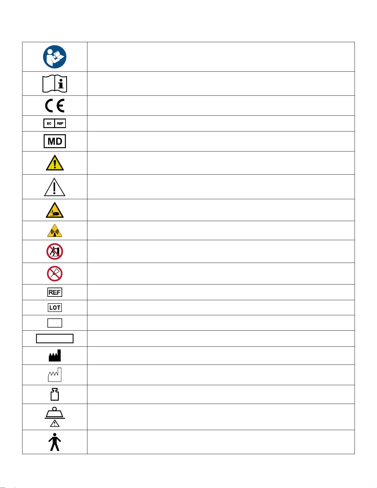
SSyymmbboollss
Refer to instruction manual/booklet
Operating instructions
CE mark
Authorized representative in the European Community
European medical device
General warning
Caution
Warning; crushing of hands
Warning; non-ionizing radiation
No pushing
Do not lubricate
Catalogue number
Lot (batch) code
Serial number
For US Patents see www.stryker.com/patents
Manufacturer
Date of manufacture
6506-109-002 Rev G.1 EN
Mass of equipment with safe working load
Safe working load
Type B applied part
Page 4

Type BF applied part
87VL
~
Cd
DATA
_
+
Lift here
Medical Equipment Classified by Underwriters Laboratories Inc. With Respect to Electric Shock,
Fire, and Mechanical Hazards Only in Accordance with ANSI/AAMI ES60601-1:2012 and CAN/
CSA-C22.2 No. 60601-1:14.
Direct current
Alternating current
Class II electrical equipment: equipment in which protection against electric shock does not rely
on basic insulation only, but in which additional safety precautions such as double insulation or
reinforced insulation are provided, there being no provision for protective earthing or reliance
upon installation conditions.
Dangerous voltage
SSMMRRTT power system
IIPPXX00
IIPPXX66
Extend
Retract
Non-protected
Protection from powerful water jets
In accordance with European Directive 2012/19/EU on Waste Electrical and Electronic
Equipment (WEEE) as amended, this symbol indicates that the product should be collected
separately for recycling. Do not dispose of as unsorted municipal waste. Contact local distributor
for disposal information. Ensure infected equipment is decontaminated prior to recycling.
WEEE Directive (2012/96/EC). Contains cadmium.
The Rechargeable Battery Recycling Corporation (RBRC) is a non-profit, public service
organization that promotes the recycling of portable rechargeable batteries. Batteries must be
delivered to a battery collection site. Visit the RBRC website (www.rbrc.org) to find a nearby
collection site or call the phone number shown on the recycling symbol.
Contains nickel cadmium cells and should be recycled accordingly
Battery terminal identification (data line, negative, and positive)
KRX
23/44
EN 6506-109-002 Rev G.1
Ni-Cd cell identification per IEC 61951-1:2003
Page 5
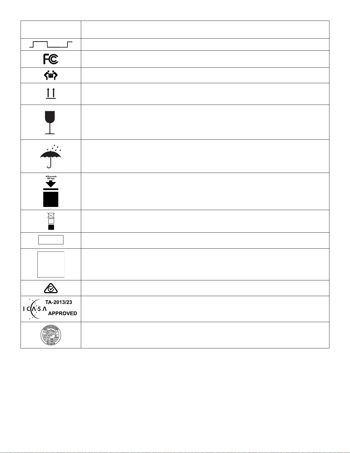
2300 mAh
<60s >300s
3
U.S.A.
TRA
Registered No:
ER35122/14
Dealer No:
DA35173/14
50
(1.2A/2h)
Battery capacity, typical charge, and duration
Cot duty cycle: 16.7% (less than 60 seconds on, more than 300 seconds off)
This device complies with Part 18 of the FCC rules
Two person lift
This way up
Fragile, handle with care
Keep dry
450 lb /205 kg weight capacity
Do not stack more than three high
English text below this symbol is intended for USA audiences only
Registered in United Arab Emirates by the Telecommunications Regulatory Authorities
Product complies with applicable EMC standards in Australia/New Zealand
Approved by independent communications authority of South Africa
Box manufacturer’s certificate - this packaging box has a minimum test value of 500 lb per sq. in
6506-109-002 Rev G.1 EN
Page 6

Page 7

TTaabbllee ooff CCoonntteennttss
Warning/Caution/Note Definition ..............................................................................................................................5
Summary of safety precautions ................................................................................................................................5
Pinch points .......................................................................................................................................................6
Mechanical stability ............................................................................................................................................6
Introduction ...............................................................................................................................................................8
Product description .................................................................................................................................................8
Indications for use...................................................................................................................................................8
Expected service life ...............................................................................................................................................9
Disposal/recycle .....................................................................................................................................................9
Contraindications ....................................................................................................................................................9
Specifications - Power-PRO.....................................................................................................................................9
Standards with required options .............................................................................................................................11
Specifications - SMRT ........................................................................................................................................... 11
Product illustration - Power-PRO............................................................................................................................ 13
Product illustration - SMRT ....................................................................................................................................14
Contact information............................................................................................................................................... 14
Serial number location - Power-PRO ...................................................................................................................... 15
Serial number location - SMRT ..............................................................................................................................15
Date of manufacture.............................................................................................................................................. 15
Preventive maintenance .........................................................................................................................................16
Lubrication ........................................................................................................................................................... 16
Regular inspection and adjustments .......................................................................................................................16
Every month or two hours ................................................................................................................................. 16
Every three months or six hours.........................................................................................................................17
Every six months or 12 hours ............................................................................................................................18
Every 12 months or 24 hours.............................................................................................................................18
Foot end fastener part replacement schedule .....................................................................................................19
Maintenance record ..............................................................................................................................................19
Training record .....................................................................................................................................................20
Troubleshooting ...................................................................................................................................................... 21
Electronics and hydraulics locator ..........................................................................................................................21
Hydraulic assembly............................................................................................................................................... 22
Hydraulic assembly wiring schematics....................................................................................................................22
Electrical system block diagram – unload ................................................................................................................23
Electrical system block diagram – load....................................................................................................................23
Litter drifts (without patient weight) .........................................................................................................................24
Base drifts (without patient weight) .........................................................................................................................25
Litter does not lower in the powered mode ..............................................................................................................25
Litter does not extend in the powered mode - check motor .......................................................................................25
Litter does not extend in powered mode - check the power indicator LED ..................................................................25
Base does not retract in the powered mode............................................................................................................. 26
Base does not extend in the manual mode ..............................................................................................................26
Base does not retract in the manual mode ..............................................................................................................26
Litter does not retract in the manual mode (with patient weight) ................................................................................26
Litter does not extend in the manual mode .............................................................................................................. 26
High speed retract does not engage .......................................................................................................................26
LCD error codes - main micro ................................................................................................................................26
LCD error codes - safety micro............................................................................................................................... 27
Main cable assembly............................................................................................................................................. 28
Main cable assembly wiring schematics..................................................................................................................29
Control board assembly......................................................................................................................................... 29
Control board assembly wiring schematics.............................................................................................................. 30
SMRT charger power LED is NOT illuminated .........................................................................................................30
SMRT charger will not charge the SMRT Pak .......................................................................................................... 30
SMRT charger indicator LEDs are NOT illuminated when the Pak is inserted.............................................................31
6506-109-002 Rev G.1 1 EN
Page 8

12 VDC automotive cable fuse replacement ............................................................................................................31
A fully charged SMRT Pak does not provide sufficient power for cot operation ...........................................................32
SMRT charger indicates a SMRT Pak error (amber LED), but the Pak performs well on the cot...................................32
Charger indicates a temperature delay (flashing amber LED), but the Pak is within the normal operating temperature
range ................................................................................................................................................................... 32
Service ....................................................................................................................................................................33
Backrest adjustment..............................................................................................................................................33
Head section replacement .....................................................................................................................................34
Backrest gas cylinder replacement ......................................................................................................................... 34
Manual release cable adjustment ...........................................................................................................................35
Filling the hydraulics assembly reservoir ................................................................................................................. 36
Wheel locking force adjustment.............................................................................................................................. 36
Steer-Lock mechanism adjustment.........................................................................................................................37
Cot retaining post adjustment.................................................................................................................................37
Cot retaining post replacement............................................................................................................................... 38
Cot retaining post screw replacement .....................................................................................................................39
Hydraulic A valve or B valve replacement ............................................................................................................... 39
Hydraulic manual release valve replacement ..........................................................................................................40
Hydraulic cylinder replacement ..............................................................................................................................41
Hydraulic hose replacement................................................................................................................................... 42
Terminal block replacement ...................................................................................................................................43
Siderail assembly replacement (standard) .............................................................................................................. 45
Siderail assembly replacement (XPS option) ........................................................................................................... 45
Ratchet assembly replacement (XPS option) ..........................................................................................................47
Release handle assembly replacement (XPS option) ...............................................................................................48
Spring handle assembly replacement (XPS option) .................................................................................................49
Cot assembly .......................................................................................................................................................... 50
Base assembly .......................................................................................................................................................56
No wheel lock option...............................................................................................................................................60
Single wheel lock option ......................................................................................................................................... 61
Dual wheel lock option............................................................................................................................................62
Caster horn assembly - 6082-002-012 ...................................................................................................................63
Adjustable caster lock assembly ............................................................................................................................64
No Steer-Lock option .............................................................................................................................................. 65
Steer-Lock, optional - 6506-038-000...................................................................................................................... 66
Steer-Lock sub assembly, head end ......................................................................................................................67
6 in. molded wheel assembly - 6060-002-010........................................................................................................ 68
Cot retaining post, right - 6085-033-000................................................................................................................. 69
Optional kickstand assembly - 6085-102-000 ........................................................................................................70
Kickstand sub assembly - 6085-002-016 ............................................................................................................... 71
Outer lift tube assembly, base pivot - 6500-301-021.............................................................................................. 72
Inner lift tube assembly, base pivot - 6500-301-022 .............................................................................................. 73
Inner lift tube, litter pivot, patient right assembly - 6500-001-034 .......................................................................... 74
Inner lift tube, litter pivot, patient left assembly - 6500-001-035.............................................................................75
Standard siderail.....................................................................................................................................................76
Siderail assembly....................................................................................................................................................77
Outer rail sub assembly, right .................................................................................................................................78
Outer rail sub assembly, left ................................................................................................................................... 79
Hall sensor assembly..............................................................................................................................................80
Sensor housing assembly ...................................................................................................................................... 81
XPS option siderail .................................................................................................................................................82
EN 2 6506-109-002 Rev G.1
Page 9

XPS main assembly, right - 6500-003-034............................................................................................................. 83
XPS main assembly, left - 6500-003-044 ...............................................................................................................84
Power assembly ..................................................................................................................................................... 85
Hydraulic sub assembly - 6500-101-030 ................................................................................................................87
Foot end assembly .................................................................................................................................................88
Button assembly - 650600010016..........................................................................................................................92
Trend - 6085-031-000 ............................................................................................................................................. 93
Trend assembly ......................................................................................................................................................94
Gatch, optional - 6500-082-000..............................................................................................................................95
Gatch assembly, optional .......................................................................................................................................96
Gatch support assembly, optional .......................................................................................................................... 99
Fowler assembly................................................................................................................................................... 100
Standard Fowler ................................................................................................................................................... 101
1865 Fowler option ...............................................................................................................................................102
Antler only head section option............................................................................................................................. 103
Head section (non-Power-LOAD compatible) - 6506-001-020 ............................................................................105
Head section (Power-LOAD compatible) - 6506-001-021 ................................................................................... 106
Head section - 6500-002-020 ............................................................................................................................... 107
Head section lock assembly - 6500-001-026 .......................................................................................................109
Bent, antler only head section - 650600020020...................................................................................................110
In-fastener shut-off assembly, optional - 6500-001-027....................................................................................... 113
No head section oxygen bottle holder option - 6506-036-000 ............................................................................. 114
Power-LOAD compatible option - 6506-127-000 ................................................................................................. 115
Performance-LOAD option - 6506-034-001 .........................................................................................................118
Power-LOAD and Performance-LOAD option - 6506-034-002............................................................................ 120
Foot end fastener assembly (Power-LOAD compatible option)...........................................................................123
G-rated restraint package - 6500-002-030 ........................................................................................................... 126
X-restraint package - 6500-001-430..................................................................................................................... 127
X-restraint package, cobalt blue - 6500-001-431 ................................................................................................. 128
RRUUGGGGEEDD™-X restraint package - 6506-001-430 ...............................................................................................129
Belt extension - 6082-160-050 ............................................................................................................................. 130
Battery pack, SMRT - 6500-033-000.................................................................................................................... 131
Defibrillator platform - 6506-170-000.................................................................................................................... 132
Defibrillator platform common components..........................................................................................................134
Equipment hook option ......................................................................................................................................... 136
Head extension option - 6100-044-000 ................................................................................................................ 137
Head extension assembly ....................................................................................................................................138
Pillow - 6100-041-030 ...........................................................................................................................................139
Load wheel, hard - 6500-101-086 ........................................................................................................................ 140
Wheel, front - 6500-001-086................................................................................................................................. 141
IV pole assembly, two-stage, right - 6500-310-000.............................................................................................. 142
IV pole assembly, three-stage, right - 6500-315-000 ...........................................................................................143
IV pole assembly, two-stage, right - 6500-101-041.............................................................................................. 144
IV pole assembly, three-stage, right - 6500-101-043 ...........................................................................................145
IV pole assembly, two-stage, left - 6500-311-000 ................................................................................................ 146
IV pole assembly, three-stage, left - 6500-316-000 ............................................................................................. 147
6506-109-002 Rev G.1 3 EN
Page 10

IV pole assembly, two-stage, left - 6500-101-042 ................................................................................................ 148
IV pole assembly, three-stage, left - 6500-101-044 ............................................................................................. 149
IV pole assembly, two-stage, dual - 6500-312-000 .............................................................................................. 150
IV pole assembly, three-stage, dual - 6500-317-000 ........................................................................................... 151
Oxygen bottle holder, foot end - 6500-240-000.................................................................................................... 152
Oxygen bottle holder assembly - 6500-101-040 .................................................................................................. 153
Oxygen bottle holder, Fowler - 6500-241-000...................................................................................................... 154
Removable oxygen bottle holder - 6080-140-000 ................................................................................................ 155
Retractable head section oxygen bottle holder - 6085-046-000 .......................................................................... 156
Base storage net - 6500-160-000 ......................................................................................................................... 157
Backrest pouch - 6500-130-000 ...........................................................................................................................158
Head end storage flat - 6500-128-000.................................................................................................................. 159
Transfer flat........................................................................................................................................................... 160
Knee Gatch bolster mattress - 6500-002-150 ...................................................................................................... 161
Knee Gatch bolster mattress, gray - 6506-002-150 ............................................................................................. 162
Knee Gatch bolster mattress, XPS - 6500-003-130 ............................................................................................. 163
Knee Gatch bolster mattress grey, XPS - 6506-003-130..................................................................................... 164
Safety hook, short - 6060-036-017 / Safety hook, long - 6060-036-018 / Safety hook, J - 6092-036018
........................................................................................................................................................................ 165
Recycling passport ...............................................................................................................................................166
650600010016 ................................................................................................................................................... 166
6500-201-010 ....................................................................................................................................................... 167
6500-201-148 ....................................................................................................................................................... 168
6500-101-010 ....................................................................................................................................................... 169
6500-002-159 ....................................................................................................................................................... 170
6500-001-214 ....................................................................................................................................................... 171
6500-002-028 ....................................................................................................................................................... 172
6500-102-015 ....................................................................................................................................................... 173
EMC information ................................................................................................................................................... 174
EN 4 6506-109-002 Rev G.1
Page 11

WWaarrnniinngg//CCaauuttiioonn//NNoottee DDeeffiinniittiioonn
The words WWAARRNNIINNGG, CCAAUUTTIIOONN, and NNOOTTEE carry special meanings and should be carefully reviewed.
WWAARRNNIINNGG
Alerts the reader about a situation which, if not avoided, could result in death or serious injury. It may also describe
potential serious adverse reactions and safety hazards.
CCAAUUTTIIOONN
Alerts the reader of a potentially hazardous situation which, if not avoided, may result in minor or moderate injury to the
user or patient or damage to the product or other property. This includes special care necessary for the safe and effective
use of the device and the care necessary to avoid damage to a device that may occur as a result of use or misuse.
NNoottee -- Provides special information to make maintenance easier or important instructions clearer.
SSuummmmaarryy ooff ssaaffeettyy pprreeccaauuttiioonnss
Always read and strictly follow the warnings and cautions listed on this page. Service only by qualified personnel.
WWAARRNNIINNGG
• Always keep your hands clear of the red safety bar pivots when you load, unload, or change the height position of the
cot.
• Always use both hands when you transport the cot.
• PPoowweerr--PPRROO with the PPoowweerr--LLOOAADD compatibility option operates primarily at these frequencies: 70 - 85 kHz for
inductive charging and 13.56 MHz±7 kHz, Amplitude Modulated (OOK), ERP: -82.37 dBm. The inductive charging can
operate between these frequencies: 70 - 125 kHz. Other equipment may interfere with the PPoowweerr--LLOOAADD system, even
if that other equipment complies with CISPR emission requirements.
• Always relieve pressure before you disconnect hydraulic or other lines. Escaping fluid under pressure can penetrate the
skin and cause serious injury. Tighten all connections before you apply pressure. If an accident occurs, see a doctor
immediately.
• Do not use bare hands to check for hydraulic leaks.
CCAAUUTTIIOONN
• Improper usage of the product can cause injury to the patient or operator. Operate the product only as described in this
manual.
• Do not modify the product or any components of the product. Modifying the product can cause unpredictable operation
resulting in injury to patient or operator. Modifying the product also voids its warranty.
• This equipment has been tested and found to comply with the limits for a Class A digital device, pursuant to part 15 of
the FCC Rules. These limits are designed to provide reasonable protection against harmful interference when the
equipment is operated in a commercial environment. This equipment generates, uses, and can radiate radio frequency
energy and, if not installed and used in accordance with the instruction manual, may cause harmful interference to radio
communications. Operation of this equipment in a residential area is likely to cause harmful interference in which case
the user will be required to correct the interference at their expense.
• Always use authorized parts to avoid the risk of product damage.
• Always check hoses and lines regularly to avoid damage to the cot. Check and tighten loose connections. Hydraulic
lines, hoses, and connections can fail or loosen due to physical damage, kinks, age, and environment exposure.
• Do not tip the cot onto its load wheels and actuate the product as this will allow air to enter the hydraulic system.
• Do not lubricate the bearings in the X-frame as it will degrade the performance of the cot and may void its warranty.
• The cot retaining post is shipped pre-configured for an X-frame cot. If the fastener has been configured for an H-frame
cot, you must adjust the retaining post to accommodate the fastener.
• The use of accessories, transducers, and cables, other than those specified or provided by the manufacturer, could
result in increased electromagnetic emissions or decreased electromagnetic immunity and result in improper operation.
6506-109-002 Rev G.1 5 EN
Page 12
• The emissions characteristics of this equipment make it suitable for use in industrial areas and hospitals (CISPR 11
class A). If it is used in a residential environment, for which CISPR 11 class B is normally required, this equipment might
not offer adequate protection to radio frequency communication services. The user might need to take mitigation
measures, such as relocating or reorienting the equipment.
• Portable RF communications equipment, including peripherals such as antenna cables and external antennas, should
be used no closer than 12 inches (30 cm) to any part of PPoowweerr--PPRROO and SSMMRRTT charger, including cables specified by
the manufacturer.
• Avoid stacking or placing other equipment adjacent to PPoowweerr--PPRROO and SSMMRRTT charger to prevent improper operation of
the products. If such use is necessary, carefully observe PPoowweerr--PPRROO and SSMMRRTT charger and the other equipment to
make sure that they are operating properly.
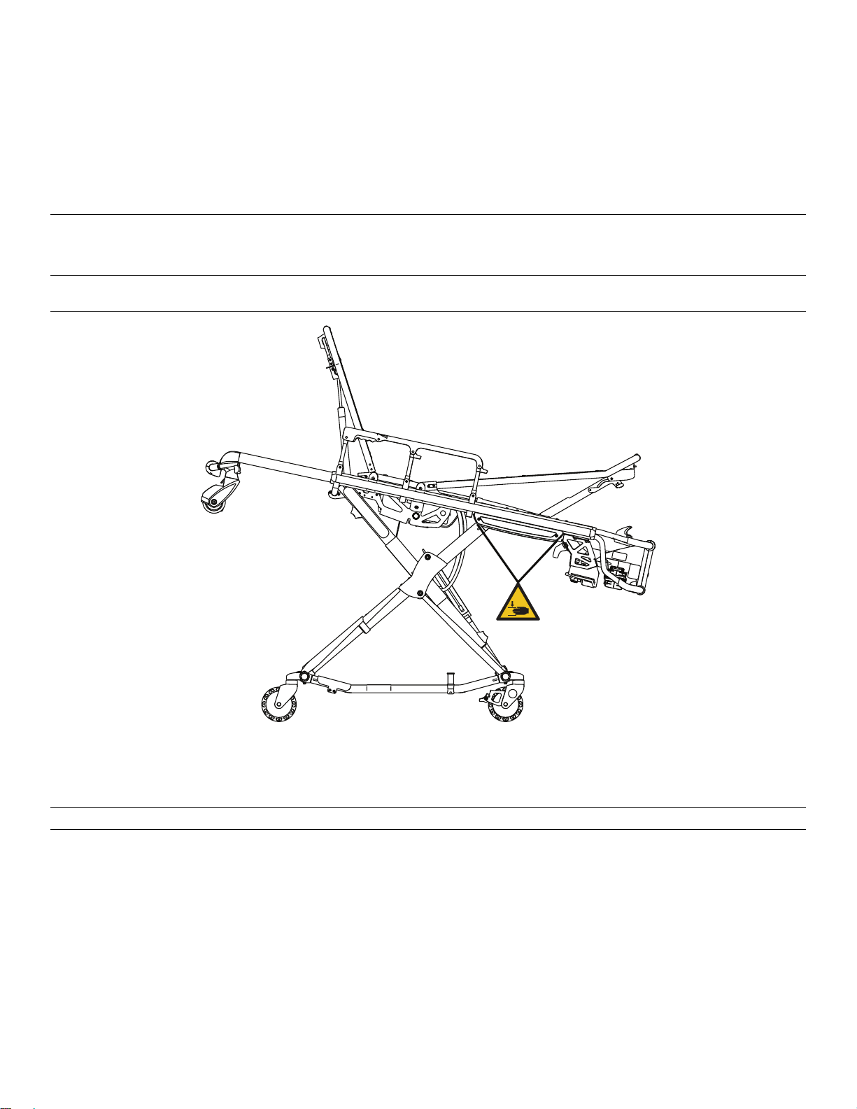
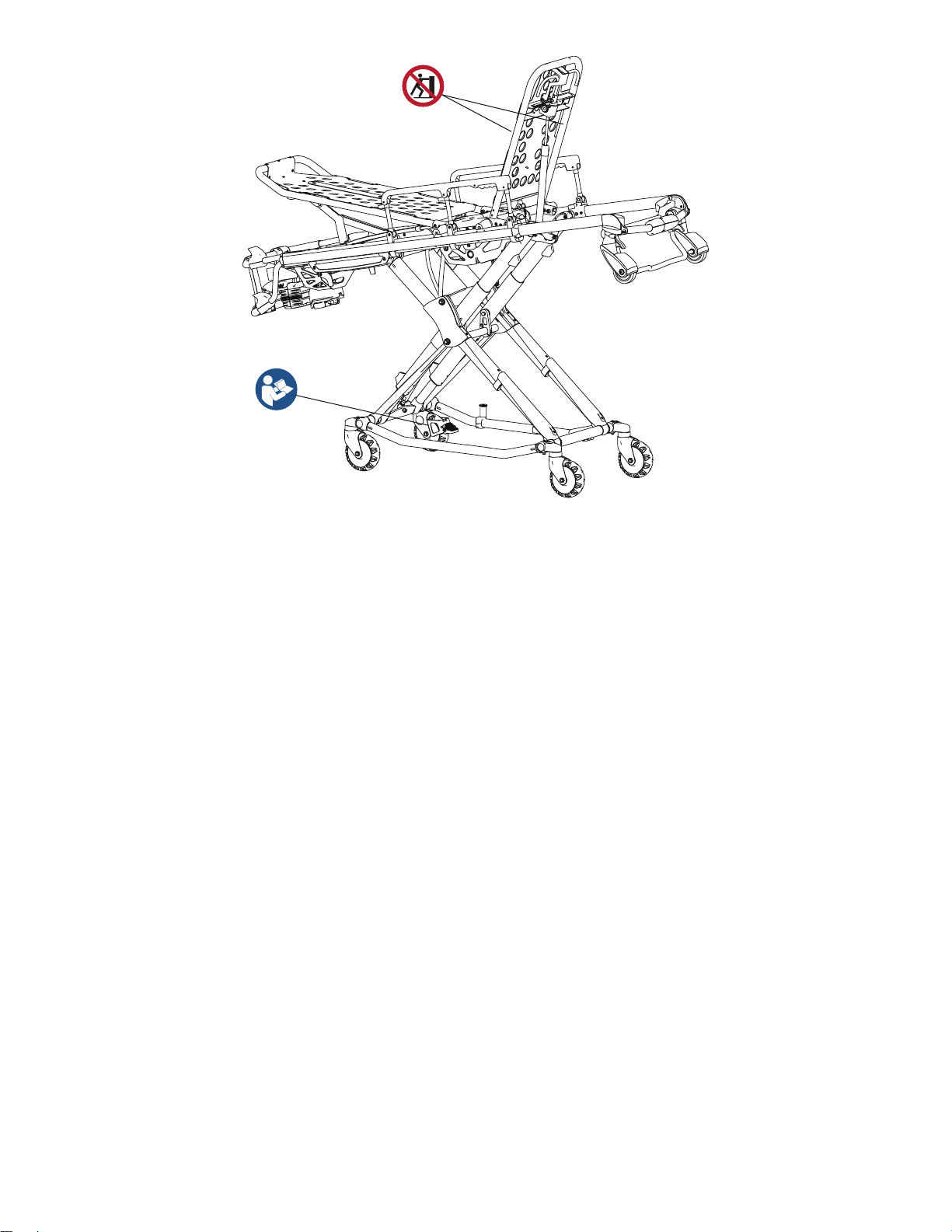
PPiinncchh ppooiinnttss
WWAARRNNIINNGG -- Always keep your hands clear of the red safety bar pivots when you load, unload, or change the height
position of the cot.
FFiigguurree 11 –– PPiinncchh ppooiinnttss
MMeecchhaanniiccaall ssttaabbiilliittyy
WWAARRNNIINNGG -- Always use both hands when you transport the cot.
EN 6 6506-109-002 Rev G.1
Page 13
FFiigguurree 22 –– MMeecchhaanniiccaall ssttaabbiilliittyy
NNoottee
• If the cot is on a plane steeper than five degrees, place the cot in the lowest position.
• Do not use the defibrillator option and the foot end oxygen bottle holder option at the same time.
6506-109-002 Rev G.1 7 EN
Page 14

IInnttrroodduuccttiioonn
This manual assists you with the operation or maintenance of your Stryker product. Read this manual before operating or
maintaining this product. Set methods and procedures to educate and train your staff on the safe operation or maintenance
of this product.
CCAAUUTTIIOONN
• Improper usage of the product can cause injury to the patient or operator. Operate the product only as described in this
manual.
• Do not modify the product or any components of the product. Modifying the product can cause unpredictable operation
resulting in injury to patient or operator. Modifying the product also voids its warranty.
NNoottee
• This manual is a permanent part of the product and should remain with the product even if the product is sold.
• Stryker continually seeks advancements in product design and quality. This manual contains the most current product
information available at the time of printing. There may be minor discrepancies between your product and this manual. If
you have any questions, contact Stryker Customer Service or Technical Support at 1-800-327-0770.
PPrroodduucctt ddeessccrriippttiioonn
The Stryker Model 6506 PPoowweerr--PPRROO™ XT cot is a powered ambulance cot that consists of a platform mounted on a
wheeled X-frame designed to support and transport a maximum weight of 700 lb (318 kg) in pre-hospital and hospital
environments.
The device is collapsible for use in emergency vehicles and has an adjustable load height feature to allow the device to be
set to different ambulance deck heights for proper body mechanics during loading and unloading. The NiCd batterypowered hydraulic lift system allows operators to raise and lower the cot using the powered controls, while duplicate foot
end controls on the upper and lower lift bars accommodate different operator positions or sizes. The cot is equipped with a
manual back-up release handle to allow the operation of cot functions in the event of power loss. The device is equipped
with a retractable head section for 360-degree mobility in any height position, siderails, patient securement straps, an
adjustable pneumatic backrest, and various optional accessories that assist with the transport of a patient. Maximum
patient comfort is attainable with the three different litter positions of shock, flat leg, and optional knee Gatch positioning.
The SSMMRRTT™ power system consists of a SSMMRRTT charger and a SSMMRRTT Pak. The SSMMRRTT Pak powers the hydraulic lift
system of the Stryker powered ambulance cots.
IInnddiiccaattiioonnss ffoorr uussee
The Stryker PPoowweerr--PPRROO XT is a powered wheeled stretcher, which is intended to support and transport the entire body of
a traumatized, ambulatory, or non-ambulatory human patient (includes infants and adults).
The battery-powered hydraulic lift system is intended to help reduce the effort required by the operator to raise and lower
the cot. The device is designed to support patients in a supine (horizontal) or sitting position and facilitate the transportation
of associated medical equipment (such as oxygen bottles, monitors, or pumps) in emergency or transport vehicles. This
ambulance cot is intended to be used in pre-hospital and hospital environments, and in emergency and non-emergency
applications. It is rated to a maximum capacity of 700 lb (318 kg) (sum of the patient, mattress, and accessory weight) and
the intended operators of the device are trained professionals including emergency medical service and medical care
center personnel, as well as medical first responders.
PPoowweerr--PPRROO XT is not intended for extended stay or use as a hospital bed or in devices that modify air pressure, such as
hyperbaric chambers.
EN 8 6506-109-002 Rev G.1
Page 15
EExxppeecctteedd sseerrvviiccee lliiffee
PPoowweerr--PPRROO has a seven year expected service life under normal use conditions and with appropriate periodic
maintenance.
The SSMMRRTT charger has a seven year expected service life under normal use conditions and with appropriate periodic
maintenance.
The SSMMRRTT Pak battery has a two year expected service life under normal use conditions.
DDiissppoossaall//rreeccyyccllee
Always follow the current local recommendations and/or regulations governing environmental protection and the risks
associated with recycling or disposing of the equipment at the end of its useful life.
CCoonnttrraaiinnddiiccaattiioonnss
None known.
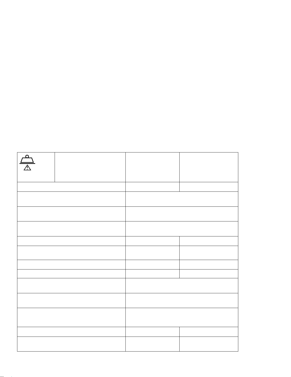
SSppeecciiffiiccaattiioonnss -- PPoowweerr--PPRROO
NNoottee -- Safe working load
indicates the sum of the
patient, mattress, and
accessory weight.
Maximum unassisted lift capacity
Backrest articulation/shock position (standard
Fowler - 6506-012-003)
Backrest articulation/shock position (1865 Fowler
option - 6506-012-004)
Backrest articulation/shock position (6506-700-
013)
Overall length/minimum length/width 81 in./63 in./23 in. 206 cm/160 cm/58 cm
Height
Weight
Caster diameter/width 6 in./2 in. 15 cm/5 cm
Minimum operators required for loading/
unloading an occupied cot
2
3
1
700 lb 318 kg
500 lb 227 kg
0° to 73°/+15°
0° to 75°/+15°
6° to 73°/+15°
Adjustable from 14 in.
to 41.5 in.
125 lb 57 kg
2
Adjustable from 36 cm to
105 cm
Minimum operators required for loading/
unloading an unoccupied cot
Recommended fastener systems Model 6370 or 6377 Floor mount type, Model 6371
Recommended loading height
Recommended working height (excluding
mattress)
6506-109-002 Rev G.1 9 EN
4
1
Wall mount type, Model 6390 PPoowweerr--LLOOAADD, Model
6392 PPeerrffoorrmmaannccee--LLOOAADD
Up to 36 in. Up to 91 cm
15.75 in. 40 cm
Page 16
Hydraulic oil Stryker part number 6500-001-293
130 °F
(54 °C)
-30 °F
(-34 °C)
130 °F
(54 °C)
-30 °F
(-34 °C)
93%0%93%
0%
1060 hPa
700
1060 hPa
700
Power system
Battery 24 VDC NiCd - SSMMRRTT power system
Charger 100-240 VAC 1.20 A,
50/60 Hz or 12 VAC 4.16 A - SSMMRRTT power system
Cot duty cycle 16.7% (less than 60 seconds on, more than 300
seconds off)
Standards (cots and chargers) ANSI/AAMI ES60601-1:2012, CAN/CSA-C22.2 No.
60601-1:14, KKK-A-1822
For standards that require specific options, see
Standards with required options
1
Cot loads over 300 lb (136 kg) may require additional assistance to meet the set cot load height.
2
Height measured from bottom of mattress at seat section to ground level.
3
Cot is weighed with one battery and without mattress and restraints.
4
Set the cot height to any ambulance deck height that ranges from 26 in. to 36 in. (66 cm to 91 cm).
(page 11).
Stryker reserves the right to change specifications without notice.
PPoowweerr--PPRROO XT is designed to conform to the Federal Specification for the Star-of-Life Ambulance (KKK-A-1822).
PPoowweerr--PPRROO XT is designed to be compatible with some competitive cot fastener systems.
The yellow and black color scheme is a proprietary trademark of Stryker Corporation.
Hereby, Stryker declares that the radio equipment type short range device is in compliance with Directive 2014/53/EU. The
full text of the EU declaration of conformity is available at the following internet address: http://techweb.med.strykercorp.
com/EMS/EU%20Declaration%20of%20Conformity/index.html.
Labels may be unreadable from a viewing distance greater than 12 inches.
WWAARRNNIINNGG -- PPoowweerr--PPRROO with the PPoowweerr--LLOOAADD compatibility option operates primarily at these frequencies: 70 - 85 kHz
for inductive charging and 13.56 MHz±7 kHz, Amplitude Modulated (OOK), ERP: -82.37 dBm. The inductive charging can
operate between these frequencies: 70 - 125 kHz. Other equipment may interfere with the PPoowweerr--LLOOAADD system, even if
that other equipment complies with CISPR emission requirements.
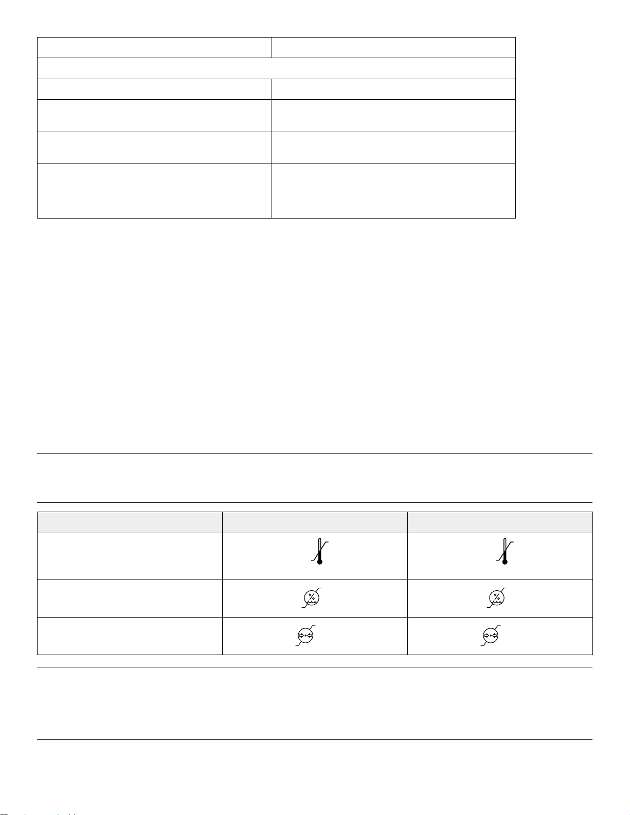
EEnnvviirroonnmmeennttaall ccoonnddiittiioonnss
OOppeerraattiioonn SSttoorraaggee aanndd ttrraannssppoorrttaattiioonn
Temperature
Relative humidity
Atmospheric pressure
CCAAUUTTIIOONN -- This equipment has been tested and found to comply with the limits for a Class A digital device, pursuant to
part 15 of the FCC Rules. These limits are designed to provide reasonable protection against harmful interference when the
equipment is operated in a commercial environment. This equipment generates, uses, and can radiate radio frequency
energy and, if not installed and used in accordance with the instruction manual, may cause harmful interference to radio
communications. Operation of this equipment in a residential area is likely to cause harmful interference in which case the
user will be required to correct the interference at their expense.
EN 10 6506-109-002 Rev G.1
Page 17

NNoottee -- In accordance with the European REACH regulation and other environmental regulatory requirements, the 6500001-210 and 6500-001-211 hydraulic hoses contain dibutyl phthalate (DBP).
SSttaannddaarrddss wwiitthh rreeqquuiirreedd ooppttiioonnss
To be compliant with the standards, you must install the following required options on your cot.
NNoottee -- Compatible cot is loaded into PPoowweerr--LLOOAADD in powered mode for crash testing.
OOppttiioonn sseelleeccttiioonn
SSttaannddaarrdd
SAE J3027 crash-test
standards with the use of a
crash-rated fastener
AS/NZS-4535 crash-test
standards with the use of a
crash-rated fastener
BS EN 1789:2007+A2:2014
crash-test standards with
the use of a crash-rated
fastener
BS EN 1865-3:2012
+A1:2015
BS EN 1865-2:2010
+A1:2015
RReessttrraaiinntt ppaacckkaaggee MMaattttrreessss OOppttiioonn
X-restraint package (6500001-430) or RUGGED-X
restraint package (6506001-430)
X-restraint package (6500001-430)
G-rated restraint package
(6500-002-030), X-restraint
package (6500-001-430), or
RUGGED-X restraint
package (6506-001-430)
Knee Gatch bolster
mattress (6500-002-150/
6506-002-150) or XPS
mattress (6500-003-130/
6506-003-130) (depending
on cot siderail)
Knee Gatch bolster
mattress (6500-002-150/
6506-002-150) or XPS
mattress (6500-003-130/
6506-003-130) (depending
on cot siderail)
Knee Gatch bolster
mattress (6500-002-150/
6506-002-150) or XPS
mattress (6500-003-130/
6506-003-130) (depending
on cot siderail)
XPS option (6506-040-000)
1865 Fowler option (6506012-004)
The Britax Meridian SICT Series No. 7200/A/2010 Convertible Child Restraint with the X-restraint package (6500-001-430)
has been dynamically crash tested with a 10 kg crash dummy to 18.2 G forward and 10 G sideward per AS/NZS-4535:
1999 crash-test standards.
SSppeecciiffiiccaattiioonnss -- SSMMRRTT
SSMMRRTT cchhaarrggeerr SSMMRRTT PPaakk AACC ppoowweerr ssuuppppllyy XXPP ppoowweerr MMeeaannWWeellll
Electrical input 13.9 VDC 4.16 A Not applicable 100-240 VAC
1.20 A 50/60 Hz
Electrical output Open circuit 40
VDC 1.20 A
Height
Width 5.125 in. (130.175
6506-109-002 Rev G.1 11 EN
2.375 in. (60.325
mm)
mm)
24 VDC NiCd 12 VDC 4.16 A 12 V 5.4 A 12 V 5.0 A
3.25 in. (82.55
mm)
4 in. (101.6 mm) 2.56 in. (65.02
1.61 in. (40.89
mm)
mm)
100-240 VAC
~1.4 A 50/60 Hz
1.32 in. (33.5 mm) 1.24 in. (31.5 mm)
2.19 in. (55.5 mm) 1.97 in. (50 mm)
100-240 VAC
~1.4 A 50/60 Hz
Page 18
SSMMRRTT cchhaarrggeerr SSMMRRTT PPaakk AACC ppoowweerr ssuuppppllyy XXPP ppoowweerr MMeeaannWWeellll
88 °F
(31 °C)
43 °F
(6 °C)
88 °F
(31 °C)
43 °F
(6 °C)
104 °F
(40 °C)
-4 °F
(-20 °C)
93%0%75%
30%
93%
0%
1060 hPa
700
1060 hPa
700
1060 hPa
500
Length 7 in. (177.8 mm) 5.75 in. (146.05
mm)
4.72 in. (119.89
mm)
4.94 in. (119.89
mm)
4.72 in. (125 mm)
Weight 1.3 lb (.59 kg) 3.8 lb (1.7 kg) .61 lb (.28 kg) .68 lb (.308 kg) .71 lb (.32 kg)
Enclosure
IPX0 IPX6 IPX0 IPX0 IPX0
protection
Equipment type Not applicable Not applicable Class II Not applicable Not applicable
Approvals ANSI/AAMI
Not applicable Not applicable Not applicable Not applicable
ES60601-1:
2012, CAN/CSAC22.2 No. 606011:14
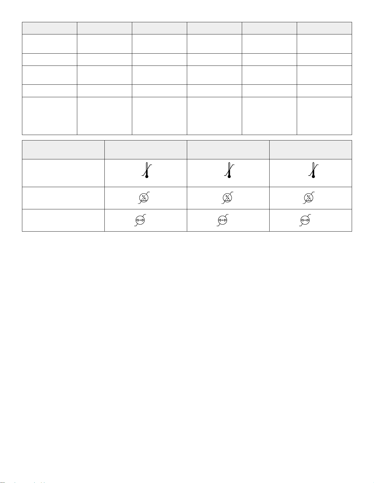
EEnnvviirroonnmmeennttaall ccoonnddiittiioonnss OOppeerraattiioonn CChhaarrggiinngg SSttoorraaggee aanndd
ttrraannssppoorrttaattiioonn
Temperature
Relative
Atmospheric pressure
Specifications are approximate and may vary from unit to unit or as a result of power supply fluctuations.
Stryker reserves the right to change specifications without notice.
EN 12 6506-109-002 Rev G.1
Page 19
PPrroodduucctt iilllluussttrraattiioonn -- PPoowweerr--PPRROO
A
B
C
D
E
F
G
H
I
K
L
M
N
O
P
Q
R
J
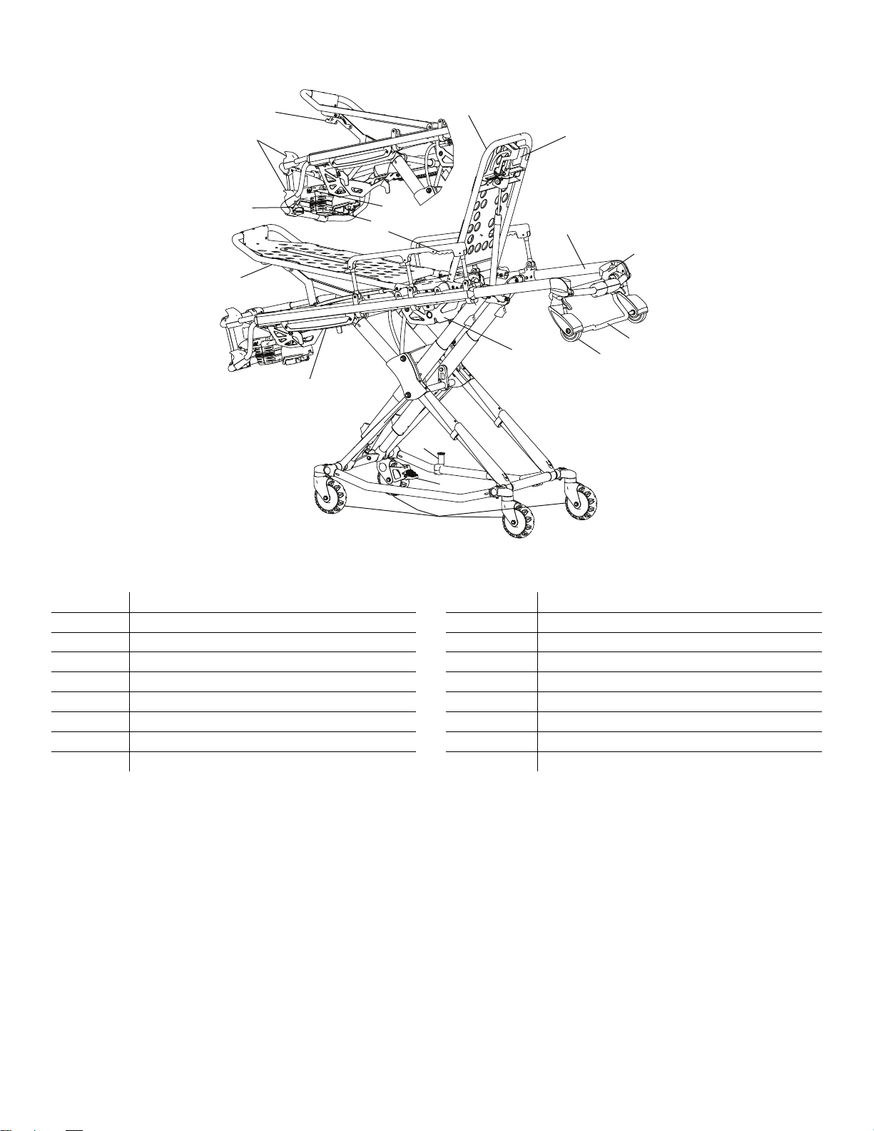
FFiigguurree 33 –– PPoowweerr--PPRROO XXTT
A Footrest release handle J Siderail release handle
B
C
D Footrest M
E
F Wheel lock O Head section release handle
G
H
I
Height adjustment switches
Manual back-up release handle
Height sensor housing (on other side)
Cot retaining post
Battery release
Battery
K
L Backrest
N Retractable head section
P
Q
R
Transport wheels
Backrest adjustment handle
Safety bar
Load wheel
Hydraulic unit
6506-109-002 Rev G.1 13 EN
Page 20
PPrroodduucctt iilllluussttrraattiioonn -- SSMMRRTT
A
C
D
E
F
H
I
G
B
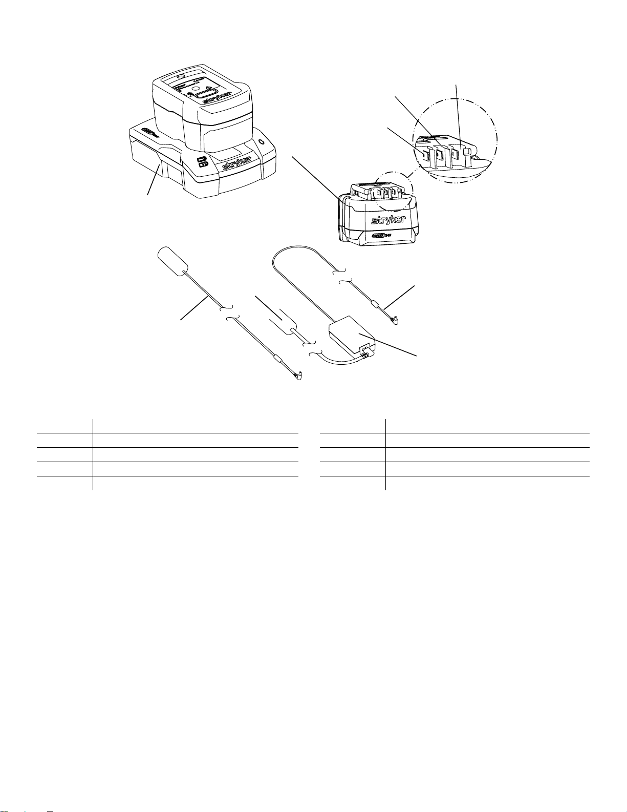
FFiigguurree 44 –– SSMMRRTT ppoowweerr ssyysstteemm
A
B SSMMRRTT Pak G Data
C DC cable H
D
E
SSMMRRTT charger
AC power supply
AC power cord
F
I
Output cord
Power (-)
Power (+)
CCoonnttaacctt iinnffoorrmmaattiioonn
Contact Stryker Customer Service or Technical Support at: 1-800-327-0770.
Stryker Medical
3800 E. Centre Avenue
Portage, MI 49002
USA
NNoottee -- The user and/or the patient should report any serious product-related incident to both the manufacturer and the
Competent authority of the European Member State where the user and/or patient is established.
To view your operations or maintenance manual online, see https://techweb.stryker.com/.
Have the serial number (A) of your Stryker product available when calling Stryker Customer Service or Technical Support.
Include the serial number in all written communication.
EN 14 6506-109-002 Rev G.1
Page 21
SSeerriiaall nnuummbbeerr llooccaattiioonn -- PPoowweerr--PPRROO
A
FFiigguurree 55 –– SSeerriiaall nnuummbbeerr llooccaattiioonn
SSeerriiaall nnuummbbeerr llooccaattiioonn -- SSMMRRTT
The serial number for the SSMMRRTT charger is located on the bottom of the unit. The lot number for the SSMMRRTT Pak is located
on the top of the SSMMRRTT Pak above the red release button.
DDaattee ooff mmaannuuffaaccttuurree
The year of manufacture is the first 2 digits of the serial number for PPoowweerr--PPRROO.
6506-109-002 Rev G.1 15 EN
Page 22

PPrreevveennttiivvee mmaaiinntteennaannccee
WWAARRNNIINNGG
• Always relieve pressure before you disconnect hydraulic or other lines. Escaping fluid under pressure can penetrate the
skin and cause serious injury. Tighten all connections before you apply pressure. If an accident occurs, see a doctor
immediately.
• Do not use bare hands to check for hydraulic leaks.
CCAAUUTTIIOONN
• Always use authorized parts to avoid the risk of product damage.
• Always check hoses and lines regularly to avoid damage to the cot. Check and tighten loose connections. Hydraulic
lines, hoses, and connections can fail or loosen due to physical damage, kinks, age, and environment exposure.
• Do not tip the cot onto its load wheels and actuate the product as this will allow air to enter the hydraulic system.
Establish and follow a maintenance schedule and keep records of the maintenance activity. Remove product from service
before you perform the preventive maintenance inspection. You may need to perform preventive maintenance checks more
often based on your level of product usage. Service only by qualified personnel.
When using maintenance products, follow the directions of the manufacturer and reference all material safety data sheets
(MSDS).
LLuubbrriiccaattiioonn
The cot has been designed to operate without the need for lubrication.
CCAAUUTTIIOONN -- Do not lubricate the bearings in the X-frame as it will degrade the performance of the cot and may void its
warranty.
RReegguullaarr iinnssppeeccttiioonn aanndd aaddjjuussttmmeennttss
The following schedule is a general guide to maintenance. Factors such as weather, terrain, geographical location, and
individual usage will alter the required maintenance schedule. If you are unsure how to perform these checks, contact your
Stryker service technician. If you are in doubt as to what intervals to follow to maintain your product, consult your Stryker
service technician. Check each routine and replace worn parts if necessary.
EEvveerryy mmoonntthh oorr ttwwoo hhoouurrss
Inspect these items every month or two hours, whichever comes first.
IItteemm IInnssppeecctt
Settings In-fastener shutoff configuration
Cylinder Extend cylinder rod. Wipe the cylinder rod with a soft cloth
and household cleaner.
Cables and wires No hanging wires from routings or connections
Manual backup release handle Manual backup release handle functions
Litter Frame and litter
Base Frame and base
Wheels All wheels are secure, roll, and swivel
EN 16 6506-109-002 Rev G.1
Page 23

IItteemm IInnssppeecctt
Head section Safety bar operates. Pull toward the head section to make
sure that the safety bar swings and rotates freely and pulls
back to the home position
Restraint Restraints function with no excessive wear (such as a bent
or broken receiver or latch plate or torn or frayed webbing)
Battery SSMMRRTT Pak housing and terminal area for cracks or
damage before first and every use
Charger SSMMRRTT charger and parts for cuts in the cord, bent pins or
contacts, or cracks in the housing before first and every
use
EEvveerryy tthhrreeee mmoonntthhss oorr ssiixx hhoouurrss
Inspect these items every three months or six hours, whichever comes first.
IItteemm IInnssppeecctt
Cylinder All fasteners are secure
No hydraulic fluid (red) leaks
Loose fittings - tighten, if needed
Hydraulics Motor mount fasteners are secure
No hydraulic fluid leaks
No leaks from reservoir
Cables and wires No damage or pinching of wiring harness, cable, or lines
No damaged connectors
Manual backup release handle Base extends and retracts when you pull the manual
backup release handle
Cot does not lower when you pull the manual backup
release handle with 100 lb (45 kg) or more on the cot
Litter All fasteners are secure
Backrest cylinder operates
Adjust pneumatic cylinder for full range of motion, if
required
Base All fasteners are secure
X-frame X-frame expands and retracts
Kickstand (optional) Retracts fully to the transport position
Bolts are tightened
Head section All fasteners are secure
Head section extends and locks
Accessories and parts (optional) All accessories and parts operate (such as IV pole, head
extension and pillow, oxygen bottle holder, and restraint
extender)
6506-109-002 Rev G.1 17 EN
Page 24

EEvveerryy ssiixx mmoonntthhss oorr 1122 hhoouurrss
Inspect these items every six months or 12 hours, whichever comes first.
IItteemm IInnssppeecctt
Hydraulics Hoses and fittings for damage or wear
Hydraulic velocity fuse - place a weight of approximately 50
lb (23 kg) on the cot, raise the cot, lift the cot with two
operators, pull the manual backup release handle, rapidly
set the cot down, and make sure that the cot does not drop
Electronic controls Extend cot to raised position, measure and check load
height
Jog function operates
High speed retract works
Switches No damage or wear to either switch
Both switches operate
Litter No bent, broken, or damaged components
No damage or tears on cot grips
Siderails operate and latch
Foot rest operates
Mattress No cracks or tears
Base No bent, broken, or damaged components
Cot retaining post is secure. If not, replace the screw
No excessive damage to X-frame guards
Wheels Free of debris
Head section No bent, broken, or damaged components
Grip bar has no excessive damage or tears
Load wheels are secure and roll
Kickstand (optional) Lubricate the kickstand spring and internal spring housing
(optional) using TTrrii--FFllooww® lubrication.
EEvveerryy 1122 mmoonntthhss oorr 2244 hhoouurrss
Inspect these items every 12 months or 24 hours, whichever comes first.
IItteemm IInnssppeecctt
Settings Cot and fastener fit and function
Safety bar connects to the vehicle safety hook
Cylinder Cylinder is adjusted - lock nut is tight and the cot stops
moving when it hits the dead stops
Manual backup release handle Returns to the stowed position
EN 18 6506-109-002 Rev G.1
Page 25

IItteemm IInnssppeecctt
Litter All welds are intact, not cracked, or broken
Warning labels present, legible
Base All welds are intact, not cracked, or broken
Wheels Check and adjust wheel locks
Retractable head section oxygen bottle holder (optional) Straps and clips for wear
Defibrillator platform (optional) Straps not frayed or torn
Latch hooks are intact and secure
FFoooott eenndd ffaasstteenneerr ppaarrtt rreeppllaacceemmeenntt sscchheedduullee
For PPeerrffoorrmmaannccee--LLOOAADD compatible cots, you must replace the foot end fastener parts every 18,078 calls. This is to make
sure that the PPeerrffoorrmmaannccee--LLOOAADD remains functional. Follow this call volume time table to remain compliant with this
requirement.
CCaallllss ppeerr ddaayy MMoonntthhss
≤ 7 Not applicable
8 77
9 67
10 59
MMaaiinntteennaannccee rreeccoorrdd
DDaattee MMaaiinntteennaannccee ooppeerraattiioonn
ppeerrffoorrmmeedd
BByy HHoouurrss
6506-109-002 Rev G.1 19 EN
Page 26

DDaattee MMaaiinntteennaannccee ooppeerraattiioonn
ppeerrffoorrmmeedd
BByy HHoouurrss
TTrraaiinniinngg rreeccoorrdd
TTrraaiinniinngg ddaattee
TTrraaiinneeee nnaammee BBaassiicc ttrraaiinniinngg RReeffrreesshheerr uuppddaattee OOwwnneerr’’ss mmaannuuaall,, iinn--
sseerrvviiccee,, ffoorrmmaall ccllaassss,, eettcc..
EN 20 6506-109-002 Rev G.1
Page 27
TTrroouubblleesshhoooottiinngg
A
B
C
D
E
F
G
H
I
K
L
J
EElleeccttrroonniiccss aanndd hhyyddrraauulliiccss llooccaattoorr
NNoottee -- Some components have been removed for clarity.
A Cap-side hydraulic hose G Manual backup release
B Electronic housing (control
C Hydraulic cylinder I Power indicator LED
D Hydraulic manifold
E LCD screen K Sensor housing (hall effects
F Main cable L Switches, height adjustment
board inside)
assembly
handle
H Manual release cable
J Rod-side hydraulic hose
sensor inside)
6506-109-002 Rev G.1 21 EN
Page 28
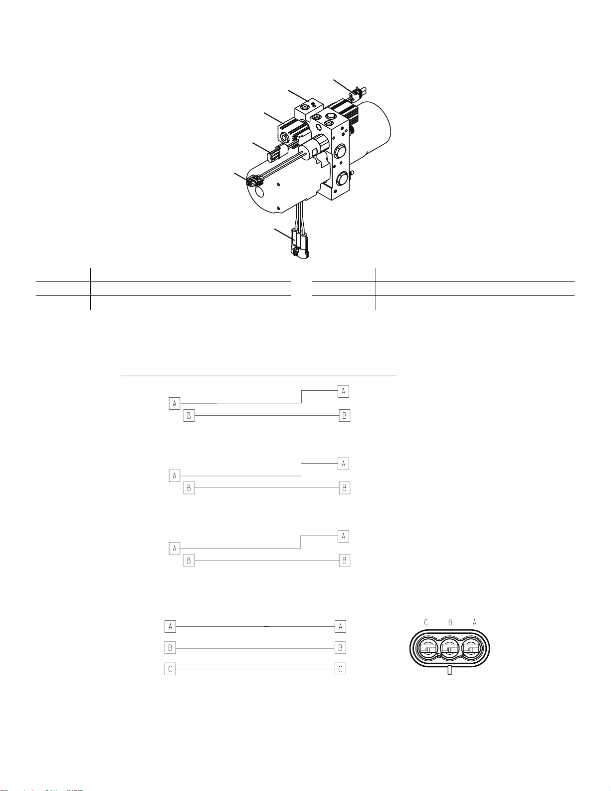
HHyyddrraauulliicc aasssseemmbbllyy
A
B
C
D
E
F
Item Item
ConnectionConnection
Pressure
switch
Pressure
switch
connector
A-valve
solenoid
A-valve
connector
B-valve
solenoid
B-valve
connector
Motor
Motor
connector
Blue
Black
Green
A A-valve connector D Motor connector
B B-valve connector E Pressure switch
C
Hydraulic manifold
F Pressure switch connector
HHyyddrraauulliicc aasssseemmbbllyy wwiirriinngg sscchheemmaattiiccss
EN 22 6506-109-002 Rev G.1
Page 29
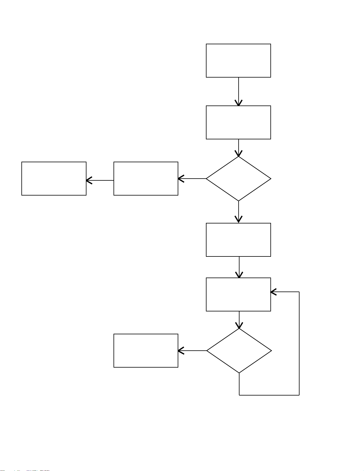
EElleeccttrriiccaall ssyysstteemm bblloocckk ddiiaaggrraamm –– uunnllooaadd
Press Extend (+) Button
Open A-Valve
Top Hall Effects
Sensor Detected?
Stop until button is pressed Jog Up
Ramp in motor (Up)
Ramp out motor and stop
Top Hall Effects
Sensor Detected?
Run motor at max speed
No
Yes
No
Yes
Lift and extend functions
EElleeccttrriiccaall ssyysstteemm bblloocckk ddiiaaggrraamm –– llooaadd
Lower and retract function
6506-109-002 Rev G.1 23 EN
Page 30
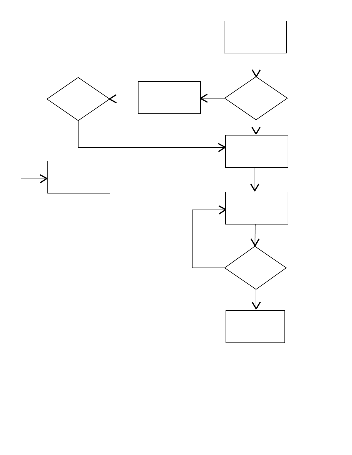
Press (–) Button
Pressure Switch
Open?
Hold B-Valve open until
button released or pressure
switch closes
Open B-Valve
Open B-Valve and Ramp in
Motor
Ramp out motor and stop,
Close B-Valve
Bottom Hall Effects
Sensor Detected?
Run motor at max speed
Pressure Switch
Open?
Yes
No
No
No
Yes
Yes
LLiitttteerr ddrriiffttss ((wwiitthhoouutt ppaattiieenntt wweeiigghhtt))
1. Check the manual release cable adjustment.
2. Change the locking manual valve.
3. Change “B” valve.
EN 24 6506-109-002 Rev G.1
Page 31

BBaassee ddrriiffttss ((wwiitthhoouutt ppaattiieenntt wweeiigghhtt))
1. Check the manual release cable adjustment.
2. Change non-locking manual valve.
3. Change “A” valve.
LLiitttteerr ddooeess nnoott lloowweerr iinn tthhee ppoowweerreedd mmooddee
Check the power indicator LED.
1. If blinking constant RED, change the battery.
2. If blinking a patterned AMBER short, short, long flash:
a. Check for broken or disconnected wires.
b. Check for 24 VDC at connector (C) on the main cable by the motor while pressing the retract (-) button. If voltage is
present, replace (in order) the solenoid and/or “B” valve. If voltage is not present, go to step c.
c. Check for 24 VDC on electronics assembly pins, 1 blue and 5 orange, on (F) while pressing the retract (-) button. If
voltage is not present, replace the electronics assembly. If voltage is present, replace the wire harness.
3. If the GREEN light turns on, but does not lower the litter, try the other switch. If the other switch works, replace the bad
switch.
LLiitttteerr ddooeess nnoott eexxtteenndd iinn tthhee ppoowweerreedd mmooddee -- cchheecckk mmoottoorr
Check the motor.
1. If the motor runs, but does not raise the cot:
a. Check the manual release cable for too much tension.
b. Lightly tap the manual locking valve.
c. Replace the manual locking valve.
2. If the motor is stalled, replace the “A” valve.
3. If the light is GREEN, but the motor does not run:
a. Check for 24 VDC at connector (E) on the main cable. If voltage is present and the motor does not run, replace the
hydraulic sub-assembly. If voltage is not present, go to step b.
b. Check for 24 VDC on electronics assembly connection (H) (-) lead on black (+) lead on green while pressing the
extend (+) button. If voltage is not present, replace the electronics assembly. If voltage is present, replace the main
cable.
LLiitttteerr ddooeess nnoott eexxtteenndd iinn ppoowweerreedd mmooddee -- cchheecckk tthhee ppoowweerr iinnddiiccaattoorr LLEEDD
Check the power indicator LED.
1. If blinking constant RED, change the battery.
2. If blinking a patterned AMBER short, short, long flash:
a. Check for broken or disconnected wires.
b. Check for 24 VDC at connector (B) on the main cable by the motor while pressing the extend (+) button. If voltage is
present, replace (in order) the solenoid and/or “A” valve. If voltage is not present, go to step c.
c. Check for 24 VDC on the electronics assembly pins, 2 white and 6 red, on (F) while pressing the extend (+) button. If
voltage is not present, replace the electronics assembly. If voltage is present replace the wire harness.
3. If the GREEN light turns on, but does not lower, try the other switch. If the other switch works, replace the bad switch.
6506-109-002 Rev G.1 25 EN
Page 32

BBaassee ddooeess nnoott rreettrraacctt iinn tthhee ppoowweerreedd mmooddee
Check the power indicator LED.
1. If blinking constant RED, change the battery.
2. If blinking a patterned AMBER short, short, long flash:
a. Check for broken or disconnected wires.
b. Check for 24 VDC at connector (B) on the main cable by the motor while pressing the extend (+) button. If voltage is
present, replace (in order) the solenoid and/or “A” valve. If voltage is not present, go to step c.
c. Check for 24 VDC on electronics assembly pins, 2 white and 6 red, on (F) while pressing the extend (+) button. If
voltage is not present, replace the electronics assembly. If voltage is present, replace the wire harness.
BBaassee ddooeess nnoott eexxtteenndd iinn tthhee mmaannuuaall mmooddee
1. Check manual cable adjustment.
2. Change the non-locking manual valve.
BBaassee ddooeess nnoott rreettrraacctt iinn tthhee mmaannuuaall mmooddee
1. Check manual release cable adjustment.
2. Change locking manual valve.
LLiitttteerr ddooeess nnoott rreettrraacctt iinn tthhee mmaannuuaall mmooddee ((wwiitthh ppaattiieenntt wweeiigghhtt))
1. Make sure that the weight is off of the casters before lowering the cot.
2. Check the manual cable adjustment.
3. Replace the locking manual valve.
LLiitttteerr ddooeess nnoott eexxtteenndd iinn tthhee mmaannuuaall mmooddee
1. Check the manual cable adjustment.
2. Change the non-locking manual valve.
HHiigghh ssppeeeedd rreettrraacctt ddooeess nnoott eennggaaggee
1. Check that the weight is off of the casters.
2. Change the pressure switch.
LLCCDD eerrrroorr ccooddeess -- mmaaiinn mmiiccrroo
LCD display Error desciption Detection period
ERR 01 RAM diagnostic failure Initialization
ERR 02 Program memory failure Initialization
EN 26 6506-109-002 Rev G.1
Page 33

ERR 03 EE diagnostic failure Initialization
ERR 04 EEPROM type and hardware type
incompatible
ERR 10 Valves diagnostic failure Initialization
ERR 61 EEPROM rev and firmware rev
incompatible
ERR 21 Motor shorted Initialization
ERR 22 Motor open Initialization
ERR 23 High power gating relay shorted Initialization
ERR 51 Motor drive FET shorted - Q15 Initialization
ERR 52 Motor drive FET shorted - Q11 Initialization
ERR 55 Motor drive FET shorted - Q16 Initialization
ERR 56 Motor drive FET shorted - Q12 Initialization
Initialization
Initialization
ERR 62 Main Micro and ASIC current limit
mismatch
ERR 80 Extend (+) or retract (-) button
detected without key
ERR 31 Electronics board over temp (280.22 °
F +/- 5%)
ERR 81 Bad hall effect sensor combination Run Time
ERR 93 Safety Micro non-responsive Run Time
Initialization
Run Time
Run Time
LLCCDD eerrrroorr ccooddeess -- ssaaffeettyy mmiiccrroo
LCD display Error description Detection period
ERR 05 RAM diagnostic failure Initialization
ERR 06 Program memory diagnostic failure Initialization
ERR 08 EEPROM type and hardware type
incompatible
6506-109-002 Rev G.1 27 EN
Initialization
Page 34

ERR 40 Data error Run Time
ERR 41 Charging failed battery voltage Run Time
ERR 42 Charging failed read battery Run Time
ERR 43 Charging failed battery charging time
or over voltage limit
ERR 44 Charging failed charging current Run Time
ERR 45 Charging failed delta temp Run Time
ERR 63 EEPROM rev and firmware rev
incompatible
ERR 83 Extend (+) or retract (-) button
detected without key
ERR 90 ASIC driving without microprocessor
instruction
Run Time
Initialization
Run Time
Run Time
MMaaiinn ccaabbllee aasssseemmbbllyy
EN 28 6506-109-002 Rev G.1
Page 35

MMaaiinn ccaabbllee aasssseemmbbllyy wwiirriinngg sscchheemmaattiiccss
CCoonnttrrooll bbooaarrdd aasssseemmbbllyy
6506-109-002 Rev G.1 29 EN
Page 36

CCoonnttrrooll bbooaarrdd aasssseemmbbllyy wwiirriinngg sscchheemmaattiiccss
SSMMRRTT cchhaarrggeerr ppoowweerr LLEEDD iiss NNOOTT iilllluummiinnaatteedd
Make sure that the AC power supply or DC cable is connected properly.
1. If using an AC power supply, make sure that the:
a. AC power cord is plugged into a wall outlet and the wall outlet has AC power.
b. AC power cord is plugged into the power supply.
c. AC power supply output cord is plugged into the charger.
2. If using a DC cable, make sure that the:
a. DC cable is plugged into a power source with 12.5 - 16 VDC
NNoottee -- The DC power supply output cord adaptor LED should be illuminated.
b. Power cord adaptor internal fuse has continuity. If not, replace the fuse. See
replacement
c. DC cable is plugged into the charger.
3. Check for 12.5 to 16 VDC at the power supply output cord that plugs into the charger.
a. If 12.5 to 16 VDC is not present, replace the power supply assembly.
b. If 12.5 to 16 VDC is present, replace the charger.
(page 31).
12 VDC automotive cable fuse
SSMMRRTT cchhaarrggeerr wwiillll nnoott cchhaarrggee tthhee SSMMRRTT PPaakk
1. Make sure that the charger power LED is illuminated.
EN 30 6506-109-002 Rev G.1
Page 37

a. If not, see
2. Make sure that the charger indicator LEDs flash when the charger is first powered.
a. If the LEDs flash at start up, go to step 3.
b. If the LEDs do not flash at start up, replace the charger.
3. Reinsert the SSMMRRTT Pak on the charger and check the charger indicator LEDs for the status of the SSMMRRTT Pak:
SMRT charger indicator LEDs are NOT illuminated when the Pak is inserted
(page 31).
a. Solid amber = a SSMMRRTT Pak error. See
(page 32).
b. Flashing amber = a temperature delay. Allow the SSMMRRTT Pak time to get to normal operating temperature. Reinstall
the SSMMRRTT Pak and recheck step 3.
c. Solid green = a fully charged and ready SSMMRRTT Pak. See
power for cot operation
(page 32).
A fully charged SMRT Pak does not provide sufficient power for cot operation
A fully charged SMRT Pak does not provide sufficient
SSMMRRTT cchhaarrggeerr iinnddiiccaattoorr LLEEDDss aarree NNOOTT iilllluummiinnaatteedd wwhheenn tthhee PPaakk iiss iinnsseerrtteedd
1. Unplug the charger, wait five seconds, and plug the charger back into the wall outlet.
2. Make sure that the charger power LED is illuminated. If not, see
30).
3. Make sure that the SSMMRRTT Pak is fully inserted into the charger. If not, reinsert the SSMMRRTT Pak fully, listen for an audible
click, and make sure that the charger indicator LEDs illuminate.
4. Try another SSMMRRTT Pak to identify any issues.
NNoottee -- Separate and label SSMMRRTT Paks during troubleshooting.
a. If the charger indicator LEDs do not illuminate, replace the charger.
b. If the charger indicator LEDs illuminate, replace the original SSMMRRTT Pak.
SMRT charger power LED is NOT illuminated
(page
1122 VVDDCC aauuttoommoottiivvee ccaabbllee ffuussee rreeppllaacceemmeenntt
TToooollss rreeqquuiirreedd::
• None
PPrroocceedduurree::
1. Unplug the adaptor cable from the plug (B) and the plug connector (A).
2. Unscrew the tip on the source end and remove the fuse (
NNoottee -- The source tip and the fuse tension spring are loose and could be dropped.
3. Install the new 10A 250V fuse into the source end of the adaptor cable and screw the tip back on.
4. Plug both ends back into the source and the charger.
5. Test the charger for functionality before you return it to service.
12 VDC automotive cable fuse replacement
(page 31)).
6506-109-002 Rev G.1 31 EN
Page 38

A
B
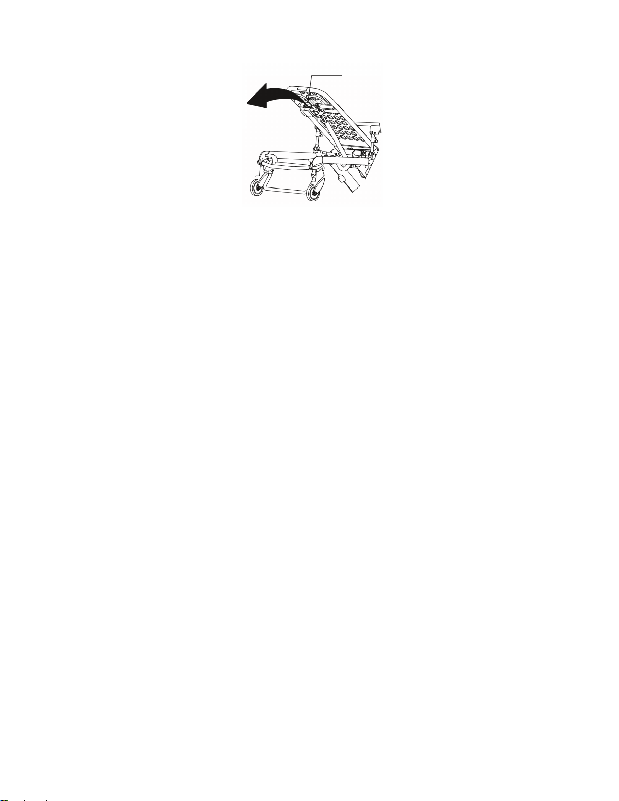
FFiigguurree 66 –– 1122 VVDDCC aauuttoommoottiivvee ccaabbllee
AA ffuullllyy cchhaarrggeedd SSMMRRTT PPaakk ddooeess nnoott pprroovviiddee ssuuffffiicciieenntt ppoowweerr ffoorr ccoott ooppeerraattiioonn
1. Fully charge the SSMMRRTT Pak for two hours.
a. If the charger indicator LED is solid green, indicating a fully charged and ready SSMMRRTT Pak, go to step 2.
b. If the charger indicator LED is solid amber, indicating a SSMMRRTT Pak error, replace the SSMMRRTT Pak.
2. Immediately following a full charge, remove the SSMMRRTT Pak from the charger and check the voltage at the power
terminals on the Pak for 26 VDC minimum.
a. If the Pak has a 26 VDC minimum, go to step 3.
b. If the VDC is less than 26 VDC, replace the Pak.
3. Wait exactly one hour and charge the SSMMRRTT Pak again.
a. If the charger indicator LED turns solid green (indicating a fully charged and ready SSMMRRTT Pak) in less than one
minute, call Stryker Technical Support.
b. If the charger indicator LED flashes green for longer than one minute, replace the Pak.
SSMMRRTT cchhaarrggeerr iinnddiiccaatteess aa SSMMRRTT PPaakk eerrrroorr ((aammbbeerr LLEEDD)),, bbuutt tthhee PPaakk ppeerrffoorrmmss
wweellll oonn tthhee ccoott
1. Fully discharge the SSMMRRTT Pak by powering a cot until the cot indicator LED flashes red.
2. Recharge the Pak.
a. If the charger indicator LED is solid green, indicating a fully charged and ready Pak, then the Pak is ready for use.
b. If the charger indicator LED is solid amber, indicating a Pak error, call Stryker Technical Support.
CChhaarrggeerr iinnddiiccaatteess aa tteemmppeerraattuurree ddeellaayy ((ffllaasshhiinngg aammbbeerr LLEEDD)),, bbuutt tthhee PPaakk iiss
wwiitthhiinn tthhee nnoorrmmaall ooppeerraattiinngg tteemmppeerraattuurree rraannggee
1. Remove the SSMMRRTT Pak from the charger and allow the Pak to cool for at least four hours at room temperature.
2. Insert the Pak into the charger.
a. If the charger indicator LED is flashing green, then the Pak is charging.
b. If the charger indicator LED is flashing amber, indicating a temperature delay, replace the Pak.
EN 32 6506-109-002 Rev G.1
Page 39

SSeerrvviiccee
A
B
C
D
E
F
G
H
J
BBaacckkrreesstt aaddjjuussttmmeenntt
TToooollss rreeqquuiirreedd::
• 1/2'' combination wrench
• 5/32'' hex wrench
• 3/32'' hex wrench
• Small slotted screwdriver
PPrroocceedduurree::
1. For easier access, move the backrest to 73 degrees (Figure 7).
a. Make sure that the cylinder (A) is threaded into the yoke (B) so that no threads are showing on the shaft of the
cylinder.
b. If threads are showing, use a 3/32'' hex wrench to remove the set screw (C) in the center of the yoke.
c. Using a small screwdriver, remove the E-clip and pin (D and E) that hold the bottom of the pneumatic cylinder.
d. Thread the cylinder shaft (A) into the yoke (B) until no threads are showing on the shaft of the cylinder.
e. Replace the E-clip and pin (D and E).
f. Using LLooccttiittee®®, replace the set screw (C).
FFiigguurree 77 –– BBaacckkrreesstt
2. Using a 1/2" combination wrench, loosen the hex nut (F) on the backrest pivot (H) while holding the set screw (G) fixed
in the pivot. (Figure 7).
3. Using a 5/32" hex wrench, turn the set screw (G) until there is no play between the backrest release handle (J) and the
pneumatic cylinder release button. (Figure 7).
4. Make sure that the backrest travels from flat to at least 73 degrees. If it does not, turn the set screw clockwise 1/2 turn.
Repeat until at least 73 degrees of travel is achieved.
6506-109-002 Rev G.1 33 EN
Page 40

5. Lower the backrest to a 5-10 degree angle and release the handle. Apply approximately 50 lb of downward force to the
A
end of the backrest. If the backrest drifts down, turn the set screw (G) counterclockwise. (Figure 7). Repeat until the
backrest does not drift downward.
6. Using the 1/2" combination wrench, tighten the hex nut (F) while holding the set screw fixed in the pivot. (Figure 7).
7. Verify proper operation before you return the product to service.
HHeeaadd sseeccttiioonn rreeppllaacceemmeenntt
TToooollss rreeqquuiirreedd::
• 7/16'' combination wrench
• 3/16'' hex wrench
PPrroocceedduurree::
1. Raise the product to the highest height position.
2. Using a 7/16" combination wrench and a 3/16" hex wrench, remove the two screws (A) that secure the cap bearings to
the base litter interface bracket (one on each side) (Figure 8).
FFiigguurree 88 –– HHeeaadd sseeccttiioonn
3. Squeeze the head release handles and remove the head section assembly.
4. Reverse steps to reinstall.
5. Verify proper operation before you return the product to service.
BBaacckkrreesstt ggaass ccyylliinnddeerr rreeppllaacceemmeenntt
TToooollss rreeqquuiirreedd::
• 3/32'' hex wrench
• Slotted screwdriver
PPrroocceedduurree::
1. Raise the cot and the backrest to the full upright position.
2. Using a 3/32" hex wrench, loosen the set screw (A) that holds the gas shaft to the yoke. (Figure 9).
EN 34 6506-109-002 Rev G.1
Page 41

3. Using a slotted screwdriver, remove the E-clip from the clevis pin that secures the bottom of the gas cylinder.
A
4. Unscrew the gas cylinder shaft from the yoke.
5. Reverse the above steps to install the new gas cylinder (see
6. Verify proper operation before you return the product to service.
FFiigguurree 99 –– BBaacckkrreesstt ggaass ccyylliinnddeerr
Backrest adjustment
(page 33)).
MMaannuuaall rreelleeaassee ccaabbllee aaddjjuussttmmeenntt
TToooollss rreeqquuiirreedd::
• 8 mm combination wrench
• 10 mm combination wrench
• (2) Weights (50 lb each)
PPrroocceedduurree::
1. Support the litter so no weight is on the base.
2. Make sure that the manual release cable is intact (A). (
3. Using a 10 mm combination wrench, loosen the cable lock nut (B). (
4. Using an 8 mm combination wrench, adjust the tension on the manual release cable so it just starts to touch the manual
release dual pull bracket (C). (
NNoottee -- Make sure that the manual release dual pull bracket is not tight against the manual valve nuts.
5. Tighten the cable lock nut.
6. Place 50 lb of weight on the hydraulic skin.
7. Load height must read 34 1/2" to 35 1/2".
8. Place 100 lb of weight on the hydraulic skin, raise cot to the highest height position, pull the manual release handle, and
make sure that the cot does not drop.
9. Remove 100 lb of weight, raise the cot to full height, pull the manual release handle, and make sure that the cot drops.
NNoottee -- If steps 6-9 do not work properly, repeat steps 3-9.
10.Verify proper operation before you return the product to service.
Manual release cable adjustment
Manual release cable adjustment
Manual release cable adjustment
(page 35)).
(page 35)).
(page 35)).
6506-109-002 Rev G.1 35 EN
Page 42

A
B
C
FFiigguurree 1100 –– MMaannuuaall rreelleeaassee ccaabbllee
A
FFiilllliinngg tthhee hhyyddrraauulliiccss aasssseemmbbllyy rreesseerrvvooiirr
Use only Mobil Mercon®® V Synthetic Blend Oil (6500-001-293) when you fill the hydraulics assembly reservoir.
NNoottee -- Any time you work with the hydraulics you may lose some oil.
TToooollss rreeqquuiirreedd::
• 3/16'' hex wrench
PPrroocceedduurree::
1. Raise the product to the highest height position.
2. Make sure that the fill port is horizontal and lined up with the hole in the motor mount.
3. Using a 3/16'' hex wrench, remove the port plug (A) (Figure 11).
4. Fill the reservoir up to the bottom of the fill port.
5. Replace the plug and raise and lower the cot a few times.
6. Verify proper operation before you return the product to service.
FFiigguurree 1111 –– HHyyddrraauulliicc aasssseemmbbllyy rreesseerrvvooiirr
WWhheeeell lloocckkiinngg ffoorrccee aaddjjuussttmmeenntt
TToooollss rreeqquuiirreedd::
• 5/32'' hex wrench
• 7/16'' combination wrench or socket
EN 36 6506-109-002 Rev G.1
Page 43

PPrroocceedduurree::
1. Using the 5/32" hex wrench and 7/16" combination wrench or socket, remove and save the socket screw from the center
of the lock pedal. The wheel lock is initially assembled with the pedal set at the minimum locking force. The marker on
the pedal (A) is aligned with the marker on the octagonal sleeve (B) (
2. Remove the sleeve (B). Rotate the sleeve counterclockwise to increase the pedal locking force and clockwise to
decrease the locking force. Insert the sleeve into the pedal (
3. Using the 5/32" hex wrench and 7/16" combination wrench or socket, reinstall the socket screw (removed in step 1).
4. Test the pedal locking force and make sure that the pedal holds properly before you return the product to service.
FFiigguurree 1122 –– WWhheeeell lloocckkiinngg ffoorrccee aaddjjuussttmmeenntt
Wheel locking force adjustment
Wheel locking force adjustment
(page 36)).
(page 36)).
SStteeeerr--LLoocckk mmeecchhaanniissmm aaddjjuussttmmeenntt
TToooollss rreeqquuiirreedd::
• 9/16'' combination wrench
PPrroocceedduurree::
1. If your Steer-Lock mechanism will not engage:
a. Using a 9/16" combination wrench, adjust the barrel nuts toward the foot end of the cot. (Figure 13).
b. After adjustment, make sure that a minimum of one full thread is exposed on each side of the barrel nut.
2. If your Steer-Lock mechanism will not disengage:
a. Using a 9/16" combination wrench, adjust the barrel nuts toward the head end of the cot. (Figure 14).
b. After adjustment, make sure that a minimum of one full thread is exposed on each side of the barrel nut.
FFiigguurree 1133 –– BBaarrrreell nnuutt aatt tthhee ffoooott eenndd FFiigguurree 1144 –– BBaarrrreell nnuutt aatt tthhee hheeaadd eenndd
CCoott rreettaaiinniinngg ppoosstt aaddjjuussttmmeenntt
TToooollss rreeqquuiirreedd::
• T30 Torx driver
6506-109-002 Rev G.1 37 EN
Page 44

CCAAUUTTIIOONN -- The cot retaining post is shipped pre-configured for an X-frame cot. If the fastener has been configured for an
A
B
C
H-frame cot, you must adjust the retaining post to accommodate the fastener.
PPrroocceedduurree::
1. Using a T30 Torx driver, remove the two socket head cap screws (A) that hold the brackets (B) to the base frame (C)
(Figure 15). Save the screws.
FFiigguurree 1155 –– CCoott rreettaaiinniinngg ppoosstt
2. Turn the bottom bracket 180˚.
3. Using a T30 Torx driver, reinstall the two socket head cap screws that were removed in step 1.
4. Verify proper operation before you return the product to service.
TToo ddeetteerrmmiinnee iiff yyoouurr ccoott iiss aann XX--ffrraammee oorr HH--ffrraammee ccoott,, llooookk ffoorr aann aarrrrooww oorr ggrroooovvee oonn tthhee bboottttoomm bbrraacckkeett ooff tthhee ccoott
rreettaaiinniinngg ppoosstt..
• The cot retaining post is set for an X-frame cot if the arrow on the bottom bracket of the retaining post points toward the
head end of the cot or if the groove in the bottom bracket is located on the inside of the patient left side of the base tube.
• The cot retaining post is set for an H-frame cot if the arrow on the bottom bracket of the retaining post points toward the
foot end of the cot or if the groove in the bottom bracket is located on the outside of the patient left side of the base tube.
CCoott rreettaaiinniinngg ppoosstt rreeppllaacceemmeenntt
TToooollss rreeqquuiirreedd::
• T30 Torx driver
• 5/32'' hex wrench
• Torque wrench (in-lb)
PPrroocceedduurree::
1. Raise the product to the highest height position.
2. Turn the cot on the patient left side.
NNoottee -- Locate the arrow or groove on the bottom bracket. The replacement retaining post bracket will need to be
assembled in the same orientation.
3. Using a T30 Torx driver, remove the two socket head cap screws (A) that secure the current cot retaining post to the
base tube (B) (Figure 16). Discard the screws and cot retaining post.
4. Insert the button head cap screw (C) through the retaining post cap (D) and post tube (E), and then into the top pin
bracket (F) (Figure 16).
5. Using a 5/32" hex wrench, tighten the button head cap screw (C) completely to secure the retaining post cap (D) and
post tube (E) to the top pin bracket (F) (Figure 16). Using a torque wrench, torque the screw to 100-140 in-lb.
EN 38 6506-109-002 Rev G.1
Page 45

6. Assemble the cot retaining post across the base tube. Align the holes of the brackets and insert two socket head cap
A
B
C
D
E
F
G
screws (A) into the threaded holes of the bottom pin bracket (G) (Figure 16).
7. Using a T30 Torx driver, tighten the two socket head cap screws completely.
8. Verify proper operation before you return the product to service.
NNoottee -- Adjustment of the rail clamp assembly may be required in order to compensate for any variation in cot retaining post
position depending on the ambulance cot manufacturer and model number.
FFiigguurree 1166 –– CCoott rreettaaiinniinngg ppoosstt rreeppllaacceemmeenntt
CCoott rreettaaiinniinngg ppoosstt ssccrreeww rreeppllaacceemmeenntt
TToooollss rreeqquuiirreedd::
• T25 Torx driver
• 5/32" hex wrench
• Torque wrench (in-lb)
PPrroocceedduurree::
1. Using a T25 Torx driver or 5/32" hex wrench, remove the button head cap screw that secures the retaining post cap and
post tube to the top pin bracket. Discard the screw.
2. Using a 5/32" hex wrench, install and tighten the button head cap screw (0004-503-000) completely to secure the
retaining post cap and tube to the top portion of the retaining post assembly. Using a torque wrench, torque the screw to
100-140 in-lb.
NNoottee -- If you cannot torque the screw to 100-140 in-lb, then you must replace the entire cot retaining post (see
retaining post replacement
3. Verify proper operation before you return the product to service.
(page 38)).
Cot
HHyyddrraauulliicc AA vvaallvvee oorr BB vvaallvvee rreeppllaacceemmeenntt
TToooollss rreeqquuiirreedd::
• T25 Torx driver
• 3/4'' combination wrench
• 7/8'' combination wrench
• (2) Saw horse
PPrroocceedduurree::
1. Raise the product to the highest height position.
2. Using two saw horses, support the litter. Activate the manual release handle to relieve any hydraulic oil pressure.
6506-109-002 Rev G.1 39 EN
Page 46

3. Using a T25 Torx driver, remove the seat pan from the litter to access the hydraulic assembly.
A
B
4. Disconnect all connections to the main cable assembly.
5. Using a 3/4" combination wrench, remove the nut that secures the solenoid to the A valve (A) or B valve (B). (Figure 17).
Save the nut for reinstallation.
6. Remove the solenoid from the valve. Save the solenoid.
7. Using a 7/8" combination wrench, remove the A valve or B valve from the hydraulic subassembly. (Figure 17).
NNoottee -- Hydraulic oil will leak from the valve and manifold. Lay down towels to catch the oil.
FFiigguurree 1177 –– HHyyddrraauulliicc AA vvaallvvee oorr BB vvaallvvee rreeppllaacceemmeenntt
8. Reverse steps to reinstall.
9. Check functionality by raising and lowering the cot several times. If necessary, add hydraulic oil (see
hydraulics assembly reservoir
10.Verify proper operation before you return the product to service.
(page 36)).
Filling the
HHyyddrraauulliicc mmaannuuaall rreelleeaassee vvaallvvee rreeppllaacceemmeenntt
TToooollss rreeqquuiirreedd::
• T27 Torx driver
• 7/16'' combination wrench
• 1/8'' hex wrench
• 7/8'' hex wrench
• (2) Saw horse
PPrroocceedduurree::
1. Raise the product to the highest height position.
2. Using two saw horses, support the litter. Activate the manual release handle to relieve any hydraulic oil pressure.
3. Using a T27 Torx driver, remove the two button head cap screws (A) that secure the manual release cable bracket to
4. Using a 1/8" hex wrench, place the hex wrench through the stem at the groove in the valve body to hold the valve stem
5. Using a 7/16" combination wrench, remove the Nylock hex nut (B) from each of the valve stems. (Figure 18).
6. Using a 7/8" hex wrench, remove the valve (C or D) to be replaced. (Figure 18).
the bottom of the hydraulic subassembly. (Figure 18).
in position.
EN 40 6506-109-002 Rev G.1
Page 47

A
B
C
D
FFiigguurree 1188 –– HHyyddrraauulliicc mmaannuuaall rreelleeaassee vvaallvvee
7. Reverse steps to reinstall.
8. Check functionality by raising and lowering the cot several times. If necessary, add hydraulic oil (see
hydraulics assembly reservoir
9. Verify proper operation before you return the product to service.
(page 36)).
Filling the
HHyyddrraauulliicc ccyylliinnddeerr rreeppllaacceemmeenntt
TToooollss rreeqquuiirreedd::
• 9/16'' combination wrench
• 3/4'' combination wrench
• 11/16'' combination wrench
• 13/16'' combination wrench
• 3/8'' combination wrench
• 1/8'' hex wrench
• (2) Saw horse
PPrroocceedduurree::
1. Raise the product to the highest height position.
2. Using two saw horses, support the litter. Activate the manual release handle. Manually compress the ram to remove the
tension on the base cross tube connecting bolt.
3. Using a 3/4" and 9/16" combination wrench, remove the rod attachment pin (A), washer (B), and Nylock hex nut (C) that
secure the hydraulic cylinder to the base. (Figure 19).
4. Activate the manual release handle and fully compress the hydraulic cylinder.
5. Using an 11/16" combination wrench and a 13/16" combination wrench, remove both hoses (D) from the hydraulic
cylinder (E). (Figure 19).
NNoottee -- Hydraulic oil will leak from the hoses and cylinder. Lay down towels to catch the oil.
6. Keep the hose ends high and upright to minimize the amount of fluid lost.
7. Using a 1/8" hex wrench and 3/8" combination wrench, remove the two socket head set screws (F) and Fiberlock hex
nuts (G) that secure the hydraulic cylinder to the base. (Figure 19).
6506-109-002 Rev G.1 41 EN
Page 48

A
B
C
D
E
F
G
D
G
8. Reverse steps to reinstall.
9. Check functionality by raising and lowering the cot several times. If necessary, add hydraulic oil (see
hydraulics assembly reservoir
FFiigguurree 1199 –– HHyyddrraauulliicc ccyylliinnddeerr rreeppllaacceemmeenntt
(page 36)).
Filling the
10.Verify proper operation before you return the product to service.
HHyyddrraauulliicc hhoossee rreeppllaacceemmeenntt
TToooollss rreeqquuiirreedd::
• 11/16'' combination wrench
• 13/16'' combination wrench
• (2) Saw horse
PPrroocceedduurree::
1. Raise the product to the highest height position.
2. Using two saw horses, support the litter. Activate the manual release handle to relieve any hydraulic oil pressure.
NNoottee
• Pay attention to the routing of the hydraulic hose for reinstallation.
• Hydraulic oil will leak from the hoses and cylinder. Lay down towels to catch the oil.
3. Using a 11/16" combination wrench and a 13/16" combination wrench, remove the damaged hose (A or B). (Figure 20).
EN 42 6506-109-002 Rev G.1
Page 49

A
B
FFiigguurree 2200 –– HHyyddrraauulliicc hhoossee rreeppllaacceemmeenntt
4. Reverse steps to reinstall.
5. Check functionality by raising and lowering the cot several times. If necessary, add hydraulic oil (see
hydraulics assembly reservoir
6. Verify proper operation before you return the product to service.
(page 36)).
Filling the
TTeerrmmiinnaall bblloocckk rreeppllaacceemmeenntt
TToooollss rreeqquuiirreedd::
• T20 Torx driver
• T25 Torx driver
PPrroocceedduurree::
1. Raise the product to the highest height position.
2. Remove the battery and save for reinstallation.
3. Using a T25 Torx driver, remove the six outer button head cap screws (A) from the face plate. (Figure 21). Save all
screws for reinstallation.
4. Using a T20 Torx driver, remove the four inner delta screws (B) from the face plate to remove the face plate. (Figure 21).
Save all screws and the face plate for reinstallation.
5. Using a T20 Torx driver, remove the four delta screws (C) that secure the electronics assembly to the foot end enclosure
and pull the electronics assembly out. (Figure 21). Save all parts for reinstallation.
6506-109-002 Rev G.1 43 EN
Page 50

A
B
C
A
B
FFiigguurree 2211 –– TTeerrmmiinnaall bblloocckk rreeppllaacceemmeenntt
6. Unplug the black and red wires that connect the cot connector cable assembly (D) to the control board (E). (Figure 22).
7. Using a T20 Torx driver, remove the two delta screws (F) from the bottom plate of the foot end enclosure (G) to remove
the enclosure. (Figure 22). Save all parts for reinstallation.
EN 44 6506-109-002 Rev G.1
Page 51

D
E
F
G
FFiigguurree 2222 –– CCoonnttrrooll bbooaarrdd aanndd ccoott ccoonnnneeccttoorr ccaabbllee aasssseemmbbllyy
8. Remove the terminal block and discard.
9. Reverse steps to reinstall.
10.Check functionality by raising and lowering the cot several times.
11.Verify proper operation before you return the product to service.
SSiiddeerraaiill aasssseemmbbllyy rreeppllaacceemmeenntt ((ssttaannddaarrdd))
TToooollss rreeqquuiirreedd::
• T25 Torx driver
PPrroocceedduurree::
1. Raise the product to the highest height position.
2. Raise the siderail to the up and locked position.
3. Using a T25 Torx driver, remove the three spindle screws that secure the siderail assembly.
4. Remove the siderail.
5. Reverse steps to install the new siderail assembly.
6. Verify proper operation before you return the product to service.
SSiiddeerraaiill aasssseemmbbllyy rreeppllaacceemmeenntt ((XXPPSS ooppttiioonn))
TToooollss rreeqquuiirreedd::
• T25 Torx driver
• 1/4'' hex wrench
• 3/16'' hex wrench
• Slotted screwdriver
6506-109-002 Rev G.1 45 EN
Page 52

• Torque wrench (ft-lb)
A
B
• Rubber mallet
PPrroocceedduurree::
1. Raise the product to the highest height position.
2. Remove the mattress.
3. Using a T25 Torx driver, remove the button head cap screw (A) and black bumper (B) on the side where you are
replacing the siderail (Figure 23). Save the screw and bumper.
FFiigguurree 2233 –– SSiiddeerraaiill aasssseemmbbllyy rreeppllaacceemmeenntt ((XXPPSS))
4. Using a slotted screwdriver, remove the outer rail bumper.
NNoottee
• Hold on to the siderail main assembly when you remove the outer rail bumper to prevent the outer rail bumper from
falling off.
• The head end and middle siderail pivots may be loose and could fall off of the main assembly.
5. Using a 1/4" hex wrench, remove the socket head cap screws (C) that secure the siderail clamp (D) to the ratchet
assembly at the foot end of the main assembly (Figure 24). When you reinstall, use a torque wrench to torque both new
screws to 22 ± 3.3 ft-lb.
NNoottee -- The siderail will be loose, so do not operate or pull on the siderail.
6. Using a 3/16" hex wrench, remove the two socket head cap screws (E) that secure the middle siderail clamp (F) to the
outer rail assembly (Figure 24).
7. Using a 3/16" hex wrench, remove the two socket head cap screws (G) that secure the top and bottom of the base/litter
interface bracket to the outer rail assembly (Figure 24).
EN 46 6506-109-002 Rev G.1
Page 53

C
D
E
F
G
FFiigguurree 2244 –– RReemmoovvee tthhee ssiiddeerraaiill aasssseemmbbllyy
8. Reverse steps to reinstall. Use a rubber mallet to reinstall the outer rail bumper.
9. Verify proper operation before you return the product to service.
RRaattcchheett aasssseemmbbllyy rreeppllaacceemmeenntt ((XXPPSS ooppttiioonn))
TToooollss rreeqquuiirreedd::
• 3/32'' hex wrench
• 1/4'' hex wrench
• 3/16'' hex wrench
• Torque wrench (ft-lb)
PPrroocceedduurree::
1. Raise the product to the highest height position.
2. Raise the siderail to the up and locked position.
3. Using a 3/32" hex wrench, remove the two screws (A) that secure the ratchet cover (B) to the ratchet assembly. Remove
the cover (Figure 25).
4. Using a 1/4" hex wrench, remove the socket head cap screws (C) that secure the siderail clamp (D) to the ratchet
assembly at the foot end of the main assembly (Figure 25). When you reinstall, use a torque wrench to torque both new
screws to 22 ± 3.3 ft-lb.
5. Using a 3/16" hex wrench, remove the four screws (E) that secure the ratchet assembly (F) to the overmold assembly
and discard. Remove the ratchet assembly (Figure 25). When you reinstall, use a torque wrench to torque the four new
screws to 9.5 ± 1.5 ft-lb.
6506-109-002 Rev G.1 47 EN
Page 54

A
B
C
D
E
F
FFiigguurree 2255 –– RRaattcchheett aasssseemmbbllyy rreeppllaacceemmeenntt ((XXPPSS))
6. Grasp the ratchet assembly and pull it toward the head end of the cot to remove.
7. Reverse steps to reinstall.
8. Verify proper operation before you return the product to service.
RReelleeaassee hhaannddllee aasssseemmbbllyy rreeppllaacceemmeenntt ((XXPPSS ooppttiioonn))
TToooollss rreeqquuiirreedd::
• 3/32'' hex wrench
• Small slotted screwdriver
PPrroocceedduurree::
1. Raise the product to the highest height position.
2. Raise the siderail to the up and locked position.
3. Using a 3/32" hex wrench, remove the four screws (A) that secure the release cover (B) to the overmold assembly to
remove the release cover (Figure 26).
4. Using a small slotted screwdriver, pry the release handle return spring (C) up to remove the spring (Figure 26).
5. Grasp the release handle assembly (D), and hinge it upward on the spring side to remove it from the cover (Figure 26).
EN 48 6506-109-002 Rev G.1
Page 55

A
B
C
D
FFiigguurree 2266 –– RReelleeaassee // SSpprriinngg hhaannddllee aasssseemmbbllyy rreeppllaacceemmeenntt ((XXPPSS))
6. Reverse steps to reinstall.
7. Verify proper operation before you return the product to service.
SSpprriinngg hhaannddllee aasssseemmbbllyy rreeppllaacceemmeenntt ((XXPPSS ooppttiioonn))
TToooollss rreeqquuiirreedd::
• 3/32'' hex wrench
• Small slotted screwdriver
PPrroocceedduurree::
1. Raise the product to the highest height position.
2. Raise the siderail to the up and locked position.
3. Using a 3/32" hex wrench, remove the four screws (A) that secure the release cover (B) to the overmold assembly to
remove the release cover (Figure 26).
4. Using a small slotted screwdriver, pry the release handle return spring (C) up to remove the spring (Figure 26).
5. Reverse steps to reinstall.
6. Verify proper operation before you return the product to service.
6506-109-002 Rev G.1 49 EN
Page 56

CCoott aasssseemmbbllyy
Torque nut to
6.0 ± 0.5 Nm
Torque nut to
to 55 ± 5 ft-lb
6506-001-010 Rev AA (Reference only)
EN 50 6506-109-002 Rev G.1
Page 57

6506-109-002 Rev G.1 51 EN
Page 58

EN 52 6506-109-002 Rev G.1
Page 59

6506-109-002 Rev G.1 53 EN
Page 60

IItteemm NNuummbbeerr NNaammee QQuuaannttiittyy
A 0004-589-000 Button head cap screw 6
B 0004-592-000 Button head cap screw 6
C 0004-594-000 Button head cap screw 8
D 0004-595-000 Button head cap screw 2
E 0004-596-000 Button head cap screw 4
F 0004-614-000 Button head cap screw 2
G 0008-030-000 Socket head cap screw 2
J 0011-013-000 Washer 1
K 0016-002-000 Fiberlock hex nut 2
L 0016-028-000 Fiberlock hex nut 4
M 0016-035-000 Nylock hex nut 1
N 0016-102-000 Nylock hex nut 4
P 0025-079-000 Dome head rivet 25
R 0025-132-000 Dome head rivet 2
T 0025-133-000 Dome head rivet 8
V 0038-574-000 Crest-to-crest spring 2
W 0056-028-000 Black bumper, TPR 2
Y 0059-211-000 Nylon cable tie, 11” 2
AA 6500-031-077 Gas spring 1
AB 2030-009-901 Label, WEEE 1
AC 6506-001-926 6506 serial number tag 1
AD 6060-090-004 Label, small 1
AE 6082-001-085 2” adhesive loop pile 1
EN 54 6506-109-002 Rev G.1
Page 61

IItteemm NNuummbbeerr NNaammee QQuuaannttiittyy
AF 6082-032-045 Fowler skin 1
AG 6082-090-043 Label, Stryker, 11” 2
AH 6085-101-155 Label, weight capacity 2
AJ 6100-003-125 Straight “T” pivot 4
AK 6252-101-139 Label, do not lubricate 4
AL 6500-001-017 Magnet slider 1
AM 6500-001-018
AN 6500-001-111 Mid-section skin 1
AP 6500-001-123 Hall effects slider 1
AR 6500-001-127 Outer rail bumper 2
AT 6500-001-128 Plastic extrusion spacer 2
AU 6500-001-168 Rod attachment pin 1
AY 6500-001-195 Motor mount casting 2
BA 6500-001-196 Litter cross brace 1
BB 6500-101-233 Label, PPoowweerr--PPRROO™™ XXTT 2
BC 6500-102-015
BD 6500-002-031
BE 6506-001-012
BF 6506-101-100 Label, PPoowweerr--PPRROO™™ XXTT specification 1
Fowler assembly
Foot end assembly
Power assembly
Base assembly
(page 85) 1
(page 56) 1
(page 100) 1
(page 88) 1
BH 6506-001-901 Label, no pushing 2
BJ 6506-001-916 Label, restraint location, shoulder 2
BK 6506-001-917 Label, restraint location, waist 2
BL 6506-001-918 Label, restraint location, thigh 2
BM 6506-001-919 Label, restraint location, ankle 2
6506-109-002 Rev G.1 55 EN
Page 62

BBaassee aasssseemmbbllyy
6506-001-012 Rev AA (Reference only)
EN 56 6506-109-002 Rev G.1
Page 63

NNoottee -- Item AE (6500-001-309) not shown for clarity (mirror image of item AC (6500-001-308).
6506-109-002 Rev G.1 57 EN
Page 64

IItteemm NNuummbbeerr NNaammee QQuuaannttiittyy
A 0003-388-000 Hex head cap screw 2
B 0003-205-000 Hex head cap screw 4
C 0004-319-000 Flat head/hex socket bolt 4
D 0004-659-000 Socket head cap screw 2
E 0004-587-000 Button head cap screw 12
F 0007-086-000 Truss head screw 6
G 0014-115-000 Washer 2
H 0015-051-000 Square nut 16
J 0016-060-000 Toplock hex jam nut 4
K 0025-133-000 Dome head pop rivet 2
L 0037-083-000 Tube plug 4
M 0004-634-000 Button head cap screw 4
N 0081-244-000 Flange bearing 4
P 6060-002-010 6 in. molded wheel assembly (
6 in.
4
molded wheel assembly - 6060-002-010
(page 68))
R 0016-049-000 Nylock hex nut 4
T 6090-001-009 Caster nut 4
EN 58 6506-109-002 Rev G.1
Page 65

IItteemm NNuummbbeerr NNaammee QQuuaannttiittyy
U 6500-301-021 Outer lift tube assembly (
Outer lift tube
2
assembly, base pivot - 6500-301-021
(page 72))
V 6500-301-022 Inner lift tube assembly (
Inner lift tube
2
assembly, base pivot - 6500-301-022
(page 73))
W 6500-001-034 Inner lift tube assembly, litter pivot, right
(
Inner lift tube, litter pivot, patient right
assembly - 6500-001-034
Y 6500-001-035 Inner lift tube assembly, litter pivot, left
(
Inner lift tube, litter pivot, patient left
assembly - 6500-001-035
AA 6500-001-056 Inner tube base frame 1
AB 6500-001-090 Head end cross tube 1
AC 6500-001-308 Base strap, right 1
AD 6500-001-125 Base dead stop 2
AE 6500-001-309 Base strap, left 1
AF 6500-001-129 Plastic extrusion spacer 1
AG 6500-001-171 Cylinder mount cross tube 1
AH 6500-001-182 Stiffener bar cross tube 1
AJ 6500-001-164 Cylinder mount pivot, top 1
AK 6500-001-165 Cylinder mount pivot, bottom 1
AL 6500-001-225 “D” washer 4
AM 6500-001-166 Flange bearing 14
AN 6500-001-157 Flange bearing 2
AP 6500-001-172 Support link 2
AT 6500-001-178 Plastic extrusion spacer 2
AU 6500-001-179 Top X-frame guard, lower 2
AV 6500-001-180 Top X-frame guard, upper 2
AW 6500-001-310 Base strap clamp 2
AY 6500-001-183 Plastic extrusion spacer 2
BA 6085-001-097 Caster mount bolt 4
BB 6500-001-162 Flange bearing 4
BC 6500-001-341 Base tube pivot post 2
BD 6500-001-226 Base tube pivot bearing 4
BE 6500-001-227 Base tube pivot post 2
BF 6500-001-228 Inner lift tube sleeve 2
BG 6500-001-229 Foot base tube 2
BH 6500-001-230 Plastic extrusion spacer 1
BJ 0014-002-000 Washer 4
BK 0014-040-000 Flat washer 4
BL 0016-002-000 Fiberlock nut 4
BM 6086-200-010 Adjustable caster lock assembly 2
(page 74))
(page 75))
1
1
6506-109-002 Rev G.1 59 EN
Page 66

NNoo wwhheeeell lloocckk ooppttiioonn
6086-500-010 Rev A (Reference only)
IItteemm NNuummbbeerr NNaammee QQuuaannttiittyy
A 6082-002-012
Caster horn assembly - 6082-002-012
(page 63)
2
EN 60 6506-109-002 Rev G.1
Page 67

SSiinnggllee wwhheeeell lloocckk ooppttiioonn
6086-601-010 Rev A (Reference only)
IItteemm NNuummbbeerr NNaammee QQuuaannttiittyy
A 6082-002-012
B 6086-200-010
Caster horn assembly - 6082-002-012
(page 63)
Adjustable caster lock assembly
64)
(page
1
1
6506-109-002 Rev G.1 61 EN
Page 68

DDuuaall wwhheeeell lloocckk ooppttiioonn
6086-602-010 Rev A (Reference only)
IItteemm NNuummbbeerr NNaammee QQuuaannttiittyy
A 6086-200-010
Adjustable caster lock assembly
64)
(page
2
EN 62 6506-109-002 Rev G.1
Page 69

CCaasstteerr hhoorrnn aasssseemmbbllyy -- 66008822--000022--001122
Rev C (Reference only)
IItteemm NNuummbbeerr NNaammee QQuuaannttiittyy
A 6082-002-039 Bearing retainer 1
B 0081-227-000 Bearing 1
C 6082-002-042 Caster horn plate, left 1
D 6082-002-043 Caster horn plate, right 1
6506-109-002 Rev G.1 63 EN
Page 70

AAddjjuussttaabbllee ccaasstteerr lloocckk aasssseemmbbllyy
6086-200-010 Rev A (Reference only)
IItteemm NNuummbbeerr NNaammee QQuuaannttiittyy
A 6082-100-012 Caster horn 1
B 6080-100-032 Spring 1
C 0011-456-000 Washer 1
D 0025-153-000 Semi-tubular rivet 2
E 6506-001-900 Label 2
F 6080-300-030 Pedal, adjustable caster lock 1
G 6080-200-041 Octagonal sleeve, adjustable caster lock 1
H 0004-098-000 Hex socket button head cap screw 1
I 0016-118-000 Centerlock nut 1
EN 64 6506-109-002 Rev G.1
Page 71

NNoo SStteeeerr--LLoocckk ooppttiioonn
6506-037-000 Rev A (Reference only)
IItteemm NNuummbbeerr NNaammee QQuuaannttiittyy
A 6500-001-177 Caster mount cover 4
B 6082-002-012
C 6500-001-230 Plastic extrusion - spacer 1
Caster horn assembly - 6082-002-012
(page 63)
2
6506-109-002 Rev G.1 65 EN
Page 72

SStteeeerr--LLoocckk,, ooppttiioonnaall -- 66550066--003388--000000
Torque item
to 100 ± 15 ft-lb
Torque item
to 100 ± 15 ft-lb
Torque item
to 100 ± 15 ft-lb
Torque item
to 100 ± 15 ft-lb
Rev A (Reference only)
IItteemm NNuummbbeerr NNaammee QQuuaannttiittyy
A 0004-587-000 Button head cap screw 2
B 0004-592-000 Button head cap screw 2
C 0059-211-000 Cable tie 3
D 6500-001-177 Caster mount cover 1
E 6500-002-243 Steer-Lock pedal collar, foot end 1
F 6500-002-244 Steer-Lock cable support bracket 1
G 6500-002-245 Caster mount cover 1
H 6500-002-246 Steer-Lock overmolded pedal, foot end 1
J 6500-002-247 Steer-Lock housing cover, head end 1
K 6500-002-248 Label, Steer-Lock pedal, foot end 1
L 6500-002-249 Steer-Lock housing cover, head end 1
M 6500-002-255 Steer-Lock caster horn weldment, left 1
N 6500-002-260 Steer-Lock caster horn weldment, right 1
P 6506-002-265
Steer-Lock sub assembly, head end
1
(page 67)
EN 66 6506-109-002 Rev G.1
Page 73

SStteeeerr--LLoocckk ssuubb aasssseemmbbllyy,, hheeaadd eenndd
6506-002-265 Rev A (Reference only)
IItteemm NNuummbbeerr NNaammee QQuuaannttiittyy
A 0025-079-000 Dome head rivet 6
B 0027-036-000 Self locking implanted cotter (SLIC) pin 3
C 0081-347-000 Flange bearing 4
D 6500-002-230 Steer-Lock plunger housing 1
E 6500-002-231 Steer-Lock plunger housing 1
F 6500-002-234 Steer-Lock mechanism housing 1
G 6500-002-235 Steer-Lock mechanism housing 1
H 6500-002-236 Steer-Lock custom flange bushing 2
J 6500-002-237 Steer-Lock lock pawl 2
K 6500-002-238 Steer-Lock plunger button 2
L 6500-002-240 Steer-Lock cross tube 1
M 6500-002-241 Steer-Lock pedal, head end 1
N 6500-002-251 Steer-Lock pedal, head end 1
P 6500-002-252 Compression spring 2
R 6500-002-250 Steer-Lock push-pull flex rod assembly 1
6506-109-002 Rev G.1 67 EN
Page 74

66 iinn.. mmoollddeedd wwhheeeell aasssseemmbbllyy -- 66006600--000022--001100
Rev D (Reference only)
IItteemm NNuummbbeerr NNaammee QQuuaannttiittyy
A 6060-002-045 6 in. molded wheel 1
B 6060-002-046 Bearing spacer 1
C 0081-226-000 Bearing 2
D 0715-001-255 Wheel bushing 2
EN 68 6506-109-002 Rev G.1
Page 75

CCoott rreettaaiinniinngg ppoosstt,, rriigghhtt -- 66008855--003333--000000
Torque item C
to 100-140 in-lb
Rev E (Reference only)
IItteemm NNuummbbeerr NNaammee QQuuaannttiittyy
A 0004-160-000 Socket head cap screw 2
B 0004-591-000 Socket head cap screw 2
C 0004-503-000 Button head cap screw 1
D 0016-003-000 Nylock hex nut 2
E 6060-004-043 Retaining post cap 1
F 6060-004-044 Post tube 1
G 6080-090-108 Label, lift here 2
H 6500-101-189 Top pin bracket 1
J 6500-101-190 Bottom pin bracket 1
K 6500-001-302 Base tube protector 1
L 6085-001-056 Outer base tube weldment 1
M 6085-001-057 Outer base tube weldment 1
6506-109-002 Rev G.1 69 EN
Page 76

OOppttiioonnaall kkiicckkssttaanndd aasssseemmbbllyy -- 66008855--110022--000000
Torque item C
to 100-140 in-lb
Rev A (Reference only)
IItteemm NNuummbbeerr NNaammee QQuuaannttiittyy
A 0004-460-000 Button head socket screw 4
B 0004-515-000 Button head cap screw 2
C 0004-503-000 Button head cap screw 1
D 0004-160-000 Socket head cap screw 2
E 0016-003-000 Nylock hex nut 2
F 6080-090-108 Label, lift here 2
G 6500-001-302 Base tube protector 1
H 6060-004-043 Retaining post cap 1
J 6060-004-044 Post tube 1
K 6085-002-001 Kickstand cot retaining post bracket 1
L 6085-002-002 Kickstand top pin bracket 1
M 6085-001-056 Outer base tube weldment 1
N 6085-001-057 Outer base tube weldment 1
P 6506-001-900 Label, refer to instruction manual 2
R 6085-002-016
Kickstand sub assembly - 6085-002-016
(page 71)
1
EN 70 6506-109-002 Rev G.1
Page 77

KKiicckkssttaanndd ssuubb aasssseemmbbllyy -- 66008855--000022--001166
Rev A (Reference only)
IItteemm NNuummbbeerr NNaammee QQuuaannttiittyy
A 0004-515-000 Button head cap screw 3
B 0004-636-000 Button head cap screw 1
C 0011-302-000 Plain washer 2
D 0016-131-000 Nylock hex nut 1
E 0021-180-000 Set screw 1
F 6085-002-003 Kickstand spring housing 1
G 6085-002-004 Kickstand bottom bracket 1
H 6085-002-006 Kick bolt 1
J 6085-002-007 Kick bolt head 1
K 6085-002-008 Kick tube 1
L 6085-002-009 Kick tube cap 2
M 6085-002-011 Rocker strut, left 1
N 6085-002-012 Rocker strut, right 1
P 6085-002-013 Kickstand spacer 1
R 6085-002-014 Kickstand torsion spring 1
6506-109-002 Rev G.1 71 EN
Page 78

OOuutteerr lliifftt ttuubbee aasssseemmbbllyy,, bbaassee ppiivvoott -- 66550000--330011--002211
Rev B (Reference only)
IItteemm NNuummbbeerr NNaammee QQuuaannttiittyy
A 6500-101-327 Half shell bearing 4
B 6500-001-328 Bearing carrier, lower 1
C 6500-001-329 Bearing carrier, middle 1
D 6500-301-050 Outer lift tube weldment 1
EN 72 6506-109-002 Rev G.1
Page 79

IInnnneerr lliifftt ttuubbee aasssseemmbbllyy,, bbaassee ppiivvoott -- 66550000--330011--002222
Rev C (Reference only)
IItteemm NNuummbbeerr NNaammee QQuuaannttiittyy
A 6500-101-327 Half shell bearing 4
B 6500-001-328 Bearing carrier, lower 1
C 6500-001-329 Bearing carrier, middle 1
D 6500-301-051 Lift tube weldment, base pivot 1
6506-109-002 Rev G.1 73 EN
Page 80

IInnnneerr lliifftt ttuubbee,, lliitttteerr ppiivvoott,, ppaattiieenntt rriigghhtt aasssseemmbbllyy -- 66550000--000011--003344
Rev F (Reference only)
IItteemm NNuummbbeerr NNaammee QQuuaannttiittyy
A 0004-634-000 Button head cap screw 2
B 0055-100-075 Nut 2
C 6500-001-355 Inner lift tube weldment 1
D 6500-001-125 Dead stop 1
EN 74 6506-109-002 Rev G.1
Page 81

IInnnneerr lliifftt ttuubbee,, lliitttteerr ppiivvoott,, ppaattiieenntt lleefftt aasssseemmbbllyy -- 66550000--000011--003355
Rev F (Reference only)
IItteemm NNuummbbeerr NNaammee QQuuaannttiittyy
A 0004-634-000 Button head cap screw 2
B 0055-100-075 Nut 2
C 6500-301-053 Inner lift tube weldment 1
D 6500-001-125 Dead stop 1
6506-109-002 Rev G.1 75 EN
Page 82

SSttaannddaarrdd ssiiddeerraaiill
6506-031-000 Rev B (Reference only)
IItteemm NNuummbbeerr NNaammee QQuuaannttiittyy
A 0004-585-000 Button head cap screw 6
B 6082-026-010
C 6500-001-118 Siderail nut 6
D 6500-002-032
E 6500-002-033
F 6500-001-116 Siderail bracket 6
G 6500-001-117 Siderail clamp 4
H 0004-591-000 Socket head cap screw 12
J 6500-001-102 Base/litter interface bracket 2
Siderail assembly
Outer rail sub assembly, right
Outer rail sub assembly, left
(page 77) 2
(page 78) 1
(page 79) 1
EN 76 6506-109-002 Rev G.1
Page 83

SSiiddeerraaiill aasssseemmbbllyy
6082-026-010 Rev B (Reference only)
IItteemm NNuummbbeerr NNaammee QQuuaannttiittyy
A 6060-025-024 Top rail 1
B 6060-025-043 Spindle 3
C 6060-025-047 Spindle lock 1
D 6060-025-041 Spindle pivot 3
E 6060-025-040 Spindle pivot stop 2
F 6060-025-029 Lock release grip 1
G 6061-125-030 Lock bar casting 1
H 0038-344-000 Lock release compression spring 1
J 6060-025-035 Pivot bushing 4
K 0025-131-000 Rivet 4
6506-109-002 Rev G.1 77 EN
Page 84

OOuutteerr rraaiill ssuubb aasssseemmbbllyy,, rriigghhtt
6500-002-032 Rev C (Reference only)
IItteemm NNuummbbeerr NNaammee QQuuaannttiittyy
A 0001-004-011 Flat head cap screw 2
C 0004-613-000 Socket head cap screw 4
D 0004-848-000 Button head cap screw 2
E 0016-028-000 Fiberlock hex nut 10
F 6500-001-098 Litter dead stop, internal 1
H 6500-001-114 Outer rail extrusion 1
L 6500-001-243 IV pole backer plate 1
M 6500-001-244 IV clip backer plate 1
N 6500-001-245 Sensor housing backer plate 2
P 6500-002-028
R 6500-002-130 Litter support bracket 2
T 6500-002-131 Litter support bracket, inner 2
Hall sensor assembly
(page 80) 1
EN 78 6506-109-002 Rev G.1
Page 85

OOuutteerr rraaiill ssuubb aasssseemmbbllyy,, lleefftt
6500-002-033 Rev C (Reference only)
IItteemm NNuummbbeerr NNaammee QQuuaannttiittyy
A 0001-004-011 Flat head cap screw 2
C 0004-613-000 Socket head cap screw 4
D 0004-848-000 Button head cap screw 2
E 0016-028-000 Fiberlock hex nut 10
F 6500-001-098 Litter dead stop, internal 1
H 6500-001-115 Outer rail, right 1
L 6500-001-243 IV pole backer plate 1
M 6500-001-244 IV clip backer plate 1
N 6500-001-245 Sensor housing backer plate 2
P 6500-002-029
R 6500-002-130 Litter support bracket 2
T 6500-002-131 Litter support bracket, inner 2
Sensor housing assembly
(page 81) 1
6506-109-002 Rev G.1 79 EN
Page 86

HHaallll sseennssoorr aasssseemmbbllyy
6500-002-028 Rev A (Reference only)
IItteemm NNuummbbeerr NNaammee QQuuaannttiittyy
A 0004-596-000 Button head cap screw 1
B 6500-001-124 Sensor housing 1
C 6500-001-160 Hall effects sensor 1
D 6500-001-199 Housing cover 1
EN 80 6506-109-002 Rev G.1
Page 87

SSeennssoorr hhoouussiinngg aasssseemmbbllyy
6500-002-029 Rev A (Reference only)
IItteemm NNuummbbeerr NNaammee QQuuaannttiittyy
A 0004-596-000 Button head cap screw 1
B 6500-001-124 Sensor housing 1
C 6500-001-199 Housing cover 1
6506-109-002 Rev G.1 81 EN
Page 88

XXPPSS ooppttiioonn ssiiddeerraaiill
Torque item J
to 22 ± 3.3 ft-lb
Torque item J
to 22 ± 3.3 ft-lb
6506-040-000 Rev A (Reference only)
IItteemm NNuummbbeerr NNaammee QQuuaannttiittyy
A 6500-003-034
B 6500-003-044
C 6500-003-099 XPS siderail clamp 2
D 6500-002-032
E 6500-002-033
F 6500-001-117 Siderail clamp 2
G 0004-591-000 Socket head cap screw 8
H 6500-001-102 Base/litter interface bracket 2
J 0004-900-000 Socket head cap screw 4
XPS main assembly, right - 6500-003034
(page 83)
XPS main assembly, left - 6500-003-044
(page 84)
Outer rail sub assembly, right
Outer rail sub assembly, left
(page 78) 1
(page 79) 1
1
1
EN 82 6506-109-002 Rev G.1
Page 89

XXPPSS mmaaiinn aasssseemmbbllyy,, rriigghhtt -- 66550000--000033--003344
Torque item E
to 9.5 ± 1.5 ft-lb
Rev C (Reference only)
IItteemm NNuummbbeerr NNaammee QQuuaannttiittyy
A 0004-400-000 Socket head cap screw 2
B 0004-402-000 Socket head cap screw 2
C 0004-403-000 Socket head cap screw 2
D 0004-468-000 Button head cap screw 4
E 0004-661-000 Socket head cap screw 4
F 0023-297-000 Delta screw 4
G 6500-003-035 XPS ratchet assembly, right 1
H 6500-003-037 XPS overmold assembly, right 1
J 6500-003-043 XPS handle assembly, right 1
K 6500-003-084 Support pivot 2
L 6500-003-085 XPS spring handle 1
M 6500-003-086 XPS siderail pivot 2
N 6500-003-094 XPS release cover, right 1
P 6500-003-097 XPS pivot cover 1
R 6500-003-119 XPS ratchet cover, right/left 1
S 6500-003-121 End cap cover, right 1
6506-109-002 Rev G.1 83 EN
Page 90

XXPPSS mmaaiinn aasssseemmbbllyy,, lleefftt -- 66550000--000033--004444
Torque item E
to 9.5 ± 1.5 ft-lb
Rev C (Reference only)
IItteemm NNuummbbeerr NNaammee QQuuaannttiittyy
A 0004-400-000 Socket head cap screw 2
B 0004-402-000 Socket head cap screw 2
C 0004-403-000 Socket head cap screw 2
D 0004-468-000 Button head cap screw 4
E 0004-661-000 Socket head cap screw 4
F 0023-297-000 Delta screw 4
G 6500-003-036 XPS ratchet assembly, right 1
H 6500-003-038 XPS overmold assembly, right 1
J 6500-003-045 XPS handle assembly, right 1
K 6500-003-084 Support pivot 2
L 6500-003-085 XPS spring handle 1
M 6500-003-086 XPS siderail pivot 2
N 6500-003-097 XPS pivot cover 1
P 6500-003-102 XPS release cover, left 1
R 6500-003-120 XPS ratchet cover, right/left 1
S 6500-003-122 End cap cover, right 1
EN 84 6506-109-002 Rev G.1
Page 91

PPoowweerr aasssseemmbbllyy
6500-002-031 Rev D (Reference only)
6506-109-002 Rev G.1 85 EN
Page 92

IItteemm NNuummbbeerr NNaammee QQuuaannttiittyy
A 0004-577-000 Button head cap screw 2
B 0004-589-000 Button head cap screw 4
C 0015-052-000 Hex jam nut 1
D 0016-102-000 Nylock hex nut 2
E 0055-100-074 Well nut 6
F 6500-101-030
G 6500-001-105 Litter support cross tube 1
H 6500-001-169 Cylinder rod end 1
J 6500-002-194 Motor mount, right 1
K 6500-001-212 Motor mount cross bar 1
L 6500-001-249 Plastic extrusion spacer 1
M 6500-001-250 Plastic extrusion spacer 2
N 6500-002-294 Motor mount, left 1
P 6506-001-820 Motor can weldment 1
R 0023-333-000 Pan head sheet metal screw 2
Hydraulic sub assembly - 6500-101-030
(page 87)
1
EN 86 6506-109-002 Rev G.1
Page 93

HHyyddrraauulliicc ssuubb aasssseemmbbllyy -- 66550000--110011--003300
Rev AB (Reference only)
IItteemm NNuummbbeerr NNaammee QQuuaannttiittyy
A 6500-101-214 Manifold assembly 1
B 6500-002-034 Hydraulic cylinder assembly 1
C 6500-001-211 Hydraulic hose assembly 1
D 6500-001-210 Hydraulic hose 1
E Depatie 8506-1.9 Vonberg velocity fuse 1
F Depatie fusion bar
code label
G 6500-001-296 Cap side hose fitting, cylinder 1
H 6500-001-297 Rod side hose fitting, cylinder 1
J Depatie PPQC label Quality control label 1
Serial number label 1
6506-109-002 Rev G.1 87 EN
Page 94

FFoooott eenndd aasssseemmbbllyy
6500-102-015 Rev AA (Reference only)
EN 88 6506-109-002 Rev G.1
Page 95

1
2
3
1 Route hall sensor cable around item (AM) and through this
area
2 Route switch cables around item (AM) and through this
area
3 Route manual release cable through this area
6506-109-002 Rev G.1 89 EN
Page 96

IItteemm NNuummbbeerr NNaammee QQuuaannttiittyy
A 0004-874-000 Socket head cap screw 2
B 0004-614-000 Button head cap screw 10
C 0004-615-000 Button head cap screw 8
D 0007-086-000 Truss head screw 2
E 0011-062-000 Washer 2
F 0011-543-000 Washer 2
G 0016-131-000 Nylock hex nut 14
H 0023-162-000 Delta screw 12
J 0023-163-000 Delta screw 3
K 0025-079-000 Dome head rivet 8
L 0025-187-000 Semi-tubular rivet 1
EN 90 6506-109-002 Rev G.1
Page 97

IItteemm NNuummbbeerr NNaammee QQuuaannttiittyy
M 0028-116-000 Push nut 4
N 0038-572-000 Compression spring 2
P 6506-001-900 Label, refer to instruction manual 1
R 6500-001-131 Upper lifting bar 1
T 6500-001-132 Lower lift bar 1
U 6500-001-133 Machined extruded bracket 2
V 6500-001-134 Battery enclosure, face plate 1
W 6500-001-135 Foot end enclosure, top plate 1
Y 6500-001-136 Foot end enclosure, bottom plate 1
AA 6500-001-138 Battery release button 1
AB 6500-001-139 Battery release lock 1
AC 6500-001-140 Manual release actuator pivot 1
AD 6500-001-141 Manual release actuator lever 1
AE 6500-001-144 Transition cap 2
AF 6500-001-146 Manual release pivot pin 1
AG 6500-001-147 Single spring 1
AH 6500-001-153 Light panel orb 1
AJ 6500-001-154 Pull handle, outside 2
AK 6500-001-156 Manual release cable assembly 1
AL 6500-001-161 Hall effects cable 1
AM 6500-001-275 Wire route clip 3
AN 6500-001-358 Lower housing button, foot end 2
AP 6500-102-014 Control board assembly 1
AR 6500-002-103 Cot dongle 1
AT 6500-002-159 Cable assembly 1
AU 6500-102-216 Cot connector cable assembly 1
AV 650600010016
AW 6500-001-356 Label, SMRT power 1
Button assembly - 650600010016
92)
(page
2
6506-109-002 Rev G.1 91 EN
Page 98

BBuuttttoonn aasssseemmbbllyy -- 665500660000001100001166
Rev AA (Reference only)
IItteemm NNuummbbeerr NNaammee QQuuaannttiittyy
A 37J102-1 Socket head cap screw 3
B 650600010130 Switch 1
C 6500-001-359 Button upper housing, foot end 1
EN 92 6506-109-002 Rev G.1
Page 99

TTrreenndd -- 66008855--003311--000000
Rev A (Reference only)
IItteemm NNuummbbeerr NNaammee QQuuaannttiittyy
A 0004-592-000 Button head cap screw 4
B 0004-596-000 Button head cap screw 4
C 0016-102-000 Nylock hex nut 4
D 0025-079-000 Dome head rivet 19
E 0025-132-000 Dome head rivet 2
F 6060-090-004 Label, small 1
G 6082-001-085 2” adhesive loop pole 1
H 6500-001-019
J 6500-001-197 Foot section tube 1
K 6500-001-198 Foot section skin 1
6506-109-002 Rev G.1 93 EN
Trend assembly
(page 94) 1
Page 100

TTrreenndd aasssseemmbbllyy
6500-001-019 Rev D (Reference only)
IItteemm NNuummbbeerr NNaammee QQuuaannttiittyy
A 0008-074-000 Socket head shoulder screw 1
B 0014-067-000 Washer 2
C 0016-028-000 Hex nut 1
D 0025-133-000 Dome head rivet 4
E 0025-186-000 Semi-tubular rivet 2
F 0056-016-000 Bumper 2
G 0081-255-000 Split bearing 2
H 6500-001-107 Litter cross brace 1
J 6500-001-108 Trend release 1
K 6500-001-109 Trend support bracket 2
L 6500-001-203 Calf stand support, right 1
M 6500-001-204 Calf stand support, left 1
N 6500-001-205 Retainer, calf stand 1
P 0025-651-000 Dome head rivet 2
EN 94 6506-109-002 Rev G.1
 Loading...